

Packard Bell TS11HR, TS13HR, TS44HR Service Manual

Packard Bell EasyNote
TS11HR/TS13HR/TS44HR
SERVICEGUIDE

Revision History
Refer to the table below for the updates made to this service guide.
Date Chapter Updates
Service guide files and updates are available on the Acer/CSD Website. For more
information, go to http://csd.acer.com.tw
without notice.
. The information in this guide is subject to change
Copyright
Copyright © 2010 by Packard Bell Incorporated. All ri ghts reserved. No p art of this publication
may be reproduced, transmitted, tran sc rib ed , store d in a retr ieva l syst em , or tran sla te d int o
any language or computer language, in any form or by any means, electronic, mechanical,
magnetic, optical, chemical, manual or otherwise, without the prior written permission of
Packard Bell Incorporated.
Disclaimer
The information in this guide is subject to change without notice.
There are no representations or warranties, either expressed or implied, with respect to the
contents hereof and specifically disclaims any warranties of merchantability or fitness for any
particular purpose. The software described in this manual is sold or licensed "as is". Should
the programs prove defective following their purc h as e, the bu ye r (n ot the ma n uf ac tur e r,
distributor, or its dealer) assumes the entire cost of all necessary servicing, repair, and any
incidental or consequential damages resulting from any defect in the software.
ii

Conventions
WARNING:
!
CAUTION:
!
IMPORTANT:
+
The following conventions are used in this manual:
Indicates a potential for personal injury.
Indicates a potential loss of data or damage to equipment.
Indicates information that is important to know for the proper completion of a
procedure, choice of an option, or completing a task.
The following typographical conventions are used in this document:
Book titles, directory names, file names, path names, and program/process names are shown in
italics.
Example:
the DRS5 User's Guide
/usr/local/bin/fd
the /TPH15spool_M program
Computer output (text that represents information displayed on a computer screen, such as
menus, prompts, responses to input, and error messages) are shown in constant width.
Example:
[01] The server has been stopped
User input (text that represents information entered by a computer user, such as command
names, option letters, and words) are shown in constant width bold.
Variables contained within user input are shown in angle brackets (< >).
Example:
At the prompt, type run <file name> -m
Keyboard keys are shown in bold italics.
Example:
After entering data, press Enter.
iii

General information 0
This service guide provides all technical information relating to the basic configuration for
Packard Bell global product offering. To better fit local market req uirements and enhance
product competitiveness, your regional office may have decide d to extend the function ality of
a machine (such as add-on cards, modems, or extra memory capabilities). These localized
features are not covered in this generic service guide. In such cases, contact your regional
offices or the responsible personnel/channel to provide further technical details.
When ordering FRU parts:
Check the most up-to-date information available on your regional Web or channel. If, for
whatever reason, a part number change is made, it may not be noted in this printed service
guide.
Acer-authorized Service Providers:
Y our Acer of fice may have a dif ferent p art number code than th ose given in the FRU list in this
service guide. The list provided by your regional Acer office must be used to order FRU parts
for repair and service of customer machines.
iv

CHAPTER 1
Hardware Specifications
Features . . . . . . . . . . . . . . . . . . . . . . . . . . . . . . . . . . . . . . . . . . . . 1-5
Operating System. . . . . . . . . . . . . . . . . . . . . . . . . . . . . . . . . . . 1-5
Platform . . . . . . . . . . . . . . . . . . . . . . . . . . . . . . . . . . . . . . . . . .1-5
System Memory . . . . . . . . . . . . . . . . . . . . . . . . . . . . . . . . . . . .1-5
Display. . . . . . . . . . . . . . . . . . . . . . . . . . . . . . . . . . . . . . . . . . . .1-5
Storage Subsystem . . . . . . . . . . . . . . . . . . . . . . . . . . . . . . . . . .1-5
Audio Subsystem . . . . . . . . . . . . . . . . . . . . . . . . . . . . . . . . . . .1-6
Graphics . . . . . . . . . . . . . . . . . . . . . . . . . . . . . . . . . . . . . . . . . .1-6
Privacy Control . . . . . . . . . . . . . . . . . . . . . . . . . . . . . . . . . . . . .1-6
Optical Media Drive . . . . . . . . . . . . . . . . . . . . . . . . . . . . . . . . .1-6
Communication . . . . . . . . . . . . . . . . . . . . . . . . . . . . . . . . . . . .1-6
Dimension and Weight . . . . . . . . . . . . . . . . . . . . . . . . . . . . . . 1-7
Power Adapter and Battery. . . . . . . . . . . . . . . . . . . . . . . . . . .1-7
I/O Ports. . . . . . . . . . . . . . . . . . . . . . . . . . . . . . . . . . . . . . . . . . .1-8
Special Keys and Controls . . . . . . . . . . . . . . . . . . . . . . . . . . . . 1-8
Optional Items . . . . . . . . . . . . . . . . . . . . . . . . . . . . . . . . . . . . .1-8
Software . . . . . . . . . . . . . . . . . . . . . . . . . . . . . . . . . . . . . . . . . .1-8
Notebook Tour. . . . . . . . . . . . . . . . . . . . . . . . . . . . . . . . . . . . . . . 1-9
Top View. . . . . . . . . . . . . . . . . . . . . . . . . . . . . . . . . . . . . . . . . .1-9
Closed Front View . . . . . . . . . . . . . . . . . . . . . . . . . . . . . . . . . .1-11
Left View. . . . . . . . . . . . . . . . . . . . . . . . . . . . . . . . . . . . . . . . . .1-12
Right View . . . . . . . . . . . . . . . . . . . . . . . . . . . . . . . . . . . . . . . .1-13
Base View . . . . . . . . . . . . . . . . . . . . . . . . . . . . . . . . . . . . . . . . .1-14
Touchpad Basics . . . . . . . . . . . . . . . . . . . . . . . . . . . . . . . . . . . .1-15
Using the Keyboard . . . . . . . . . . . . . . . . . . . . . . . . . . . . . . . . .1-16
Windows Keys. . . . . . . . . . . . . . . . . . . . . . . . . . . . . . . . . . . . . .1-17
Hot Keys . . . . . . . . . . . . . . . . . . . . . . . . . . . . . . . . . . . . . . . . . .1-18
System Block Diagram . . . . . . . . . . . . . . . . . . . . . . . . . . . . . . .1-20
Specification Tables . . . . . . . . . . . . . . . . . . . . . . . . . . . . . . . . . . . 1-21
Computer specifications . . . . . . . . . . . . . . . . . . . . . . . . . . . . . .1-21
System Board Major Chips . . . . . . . . . . . . . . . . . . . . . . . . . . . .1-22
Processor. . . . . . . . . . . . . . . . . . . . . . . . . . . . . . . . . . . . . . . . . .1-22
Processor Specifications . . . . . . . . . . . . . . . . . . . . . . . . . . . . . .1-22
CPU Fan True Value Table . . . . . . . . . . . . . . . . . . . . . . . . . . . .1-23
CPU Fan True Value Table . . . . . . . . . . . . . . . . . . . . . . . . . . . .1-23
System Memory. . . . . . . . . . . . . . . . . . . . . . . . . . . . . . . . . . . . .1-23
Memory Combinations. . . . . . . . . . . . . . . . . . . . . . . . . . . . . . . .1-24
Video Interface. . . . . . . . . . . . . . . . . . . . . . . . . . . . . . . . . . . . . .1-24
BIOS . . . . . . . . . . . . . . . . . . . . . . . . . . . . . . . . . . . . . . . . . . . . .1-25
LAN Interface. . . . . . . . . . . . . . . . . . . . . . . . . . . . . . . . . . . . . . .1-25
Keyboard . . . . . . . . . . . . . . . . . . . . . . . . . . . . . . . . . . . . . . . . . .1-25
v

Hard Disk Drive (AVL components). . . . . . . . . . . . . . . . . . . . . .1-26
Super-Multi Drive. . . . . . . . . . . . . . . . . . . . . . . . . . . . . . . . . . . .1-28
LED 15.6”. . . . . . . . . . . . . . . . . . . . . . . . . . . . . . . . . . . . . . . . . .1-30
LCD Inverter (not available with this model) . . . . . . . . . . . . . . .1-30
Display Supported Resolution (LCD Supported Resolution). . .1-31
Graphics Controller . . . . . . . . . . . . . . . . . . . . . . . . . . . . . . . . . .1-31
Display Supported Resolution (GPU Supported Resolution). . .1-31
Bluetooth Interface. . . . . . . . . . . . . . . . . . . . . . . . . . . . . . . . . . .1-31
Bluetooth Module. . . . . . . . . . . . . . . . . . . . . . . . . . . . . . . . . . . .1-32
Camera . . . . . . . . . . . . . . . . . . . . . . . . . . . . . . . . . . . . . . . . . . .1-32
Mini Card . . . . . . . . . . . . . . . . . . . . . . . . . . . . . . . . . . . . . . . . . .1-32
3G Card (not available with this model). . . . . . . . . . . . . . . . . . .1-32
Audio Codec and Amplifier . . . . . . . . . . . . . . . . . . . . . . . . . . . .1-33
Audio Interface. . . . . . . . . . . . . . . . . . . . . . . . . . . . . . . . . . . . . .1-33
Wireless Module 802.11b/g/n . . . . . . . . . . . . . . . . . . . . . . . . . .1-34
Battery . . . . . . . . . . . . . . . . . . . . . . . . . . . . . . . . . . . . . . . . . . . .1-34
VRAM . . . . . . . . . . . . . . . . . . . . . . . . . . . . . . . . . . . . . . . . . . . .1-34
USB Port . . . . . . . . . . . . . . . . . . . . . . . . . . . . . . . . . . . . . . . . . .1-35
HDMI Port . . . . . . . . . . . . . . . . . . . . . . . . . . . . . . . . . . . . . . . . .1-35
AC Adapter . . . . . . . . . . . . . . . . . . . . . . . . . . . . . . . . . . . . . . . .1-35
System Power Management . . . . . . . . . . . . . . . . . . . . . . . . . . .1-36
Card Reader . . . . . . . . . . . . . . . . . . . . . . . . . . . . . . . . . . . . . . .1-36
System LED Indicator . . . . . . . . . . . . . . . . . . . . . . . . . . . . . . . .1-37
System DMA Specification . . . . . . . . . . . . . . . . . . . . . . . . . . . .1-37
System Interrupt Specification. . . . . . . . . . . . . . . . . . . . . . . . . .1-38
System IO Address Map . . . . . . . . . . . . . . . . . . . . . . . . . . . . . .1-39
System I/O Address Specifications . . . . . . . . . . . . . . . . . . . . . .1-40
CHAPTER 2
System Utilities
BIOS Setup Utility. . . . . . . . . . . . . . . . . . . . . . . . . . . . . . . . . . . . . 2-3
Navigating the BIOS Utility . . . . . . . . . . . . . . . . . . . . . . . . . . .2-3
BIOS . . . . . . . . . . . . . . . . . . . . . . . . . . . . . . . . . . . . . . . . . . . . . . . 2-4
Information. . . . . . . . . . . . . . . . . . . . . . . . . . . . . . . . . . . . . . . .2-4
Main . . . . . . . . . . . . . . . . . . . . . . . . . . . . . . . . . . . . . . . . . . . . .2-6
Security . . . . . . . . . . . . . . . . . . . . . . . . . . . . . . . . . . . . . . . . . . .2-8
Boot. . . . . . . . . . . . . . . . . . . . . . . . . . . . . . . . . . . . . . . . . . . . . .2-12
Exit. . . . . . . . . . . . . . . . . . . . . . . . . . . . . . . . . . . . . . . . . . . . . . .2-13
BIOS Flash Utilities . . . . . . . . . . . . . . . . . . . . . . . . . . . . . . . . . . . . 2-14
DOS Flash Utility. . . . . . . . . . . . . . . . . . . . . . . . . . . . . . . . . . . .2-15
WinFlash Utility . . . . . . . . . . . . . . . . . . . . . . . . . . . . . . . . . . . .2-18
Remove HDD/BIOS Password Utilities. . . . . . . . . . . . . . . . . . . . . 2-19
Removing BIOS Passwords . . . . . . . . . . . . . . . . . . . . . . . . . . . . 2-21
Miscellaneous Tools . . . . . . . . . . . . . . . . . . . . . . . . . . . . . . . . .2-23
vi

CHAPTER 3
Machine Maintenance Procedures
Introduction . . . . . . . . . . . . . . . . . . . . . . . . . . . . . . . . . . . . . . . . . 3-5
General Information . . . . . . . . . . . . . . . . . . . . . . . . . . . . . . . . . . 3-5
Recommended Equipment . . . . . . . . . . . . . . . . . . . . . . . . . . . . . 3-5
Maintenance Flowchart. . . . . . . . . . . . . . . . . . . . . . . . . . . . . . . . 3-6
Getting Started . . . . . . . . . . . . . . . . . . . . . . . . . . . . . . . . . . . . . . 3-8
Battery Pack Removal. . . . . . . . . . . . . . . . . . . . . . . . . . . . . . . .3-9
Battery Pack Installation . . . . . . . . . . . . . . . . . . . . . . . . . . . . .3-9
Dummy Card Removal . . . . . . . . . . . . . . . . . . . . . . . . . . . . . . .3-10
Dummy Card Installation . . . . . . . . . . . . . . . . . . . . . . . . . . . . .3-10
3G Card Removal . . . . . . . . . . . . . . . . . . . . . . . . . . . . . . . . . . .3-11
3G Card Installation . . . . . . . . . . . . . . . . . . . . . . . . . . . . . . . . .3-11
3G Module Removal. . . . . . . . . . . . . . . . . . . . . . . . . . . . . . . . .3-12
3G Module Installation . . . . . . . . . . . . . . . . . . . . . . . . . . . . . .3-13
Base Door Removal . . . . . . . . . . . . . . . . . . . . . . . . . . . . . . . . .3-14
Base Door Installation . . . . . . . . . . . . . . . . . . . . . . . . . . . . . . .3-14
HDD (Hard Disk Drive) Module Removal . . . . . . . . . . . . . . . . 3-16
HDD Module Installation . . . . . . . . . . . . . . . . . . . . . . . . . . . . . 3-17
HDD Carrier Removal . . . . . . . . . . . . . . . . . . . . . . . . . . . . . . . .3-18
HDD Carrier Installation. . . . . . . . . . . . . . . . . . . . . . . . . . . . . .3-18
ODD Module Removal . . . . . . . . . . . . . . . . . . . . . . . . . . . . . . .3-19
ODD Module Installation. . . . . . . . . . . . . . . . . . . . . . . . . . . . .3-20
WLAN (Wireless Local Area Network) Module Removal . . . .3-21
WLAN Module Installation . . . . . . . . . . . . . . . . . . . . . . . . . . .3-21
DIMM (Dual In-line Memory Module) Module Removal . . . . 3-22
DIMM Module Installation. . . . . . . . . . . . . . . . . . . . . . . . . . . .3-22
Palmrest Assembly Removal . . . . . . . . . . . . . . . . . . . . . . . . . .3-23
Palmrest Assembly Installation . . . . . . . . . . . . . . . . . . . . . . . .3-26
USB Module Removal. . . . . . . . . . . . . . . . . . . . . . . . . . . . . . . .3-27
USB Module Installation . . . . . . . . . . . . . . . . . . . . . . . . . . . . .3-28
Bluetooth Module Removal. . . . . . . . . . . . . . . . . . . . . . . . . . .3-29
Bluetooth Module Installation . . . . . . . . . . . . . . . . . . . . . . . .3-29
RTC Battery Removal . . . . . . . . . . . . . . . . . . . . . . . . . . . . . . . .3-30
RTC Battery Installation . . . . . . . . . . . . . . . . . . . . . . . . . . . . . .3-30
Upper Cover Removal . . . . . . . . . . . . . . . . . . . . . . . . . . . . . . .3-31
Upper Cover Installation . . . . . . . . . . . . . . . . . . . . . . . . . . . . .3-33
Power Board Removal . . . . . . . . . . . . . . . . . . . . . . . . . . . . . . .3-34
Power Board Installation . . . . . . . . . . . . . . . . . . . . . . . . . . . . .3-35
Keyboard Assembly Removal. . . . . . . . . . . . . . . . . . . . . . . . . .3-36
Keyboard Assembly Installation . . . . . . . . . . . . . . . . . . . . . . . 3-37
Touchpad Board FFC Removal. . . . . . . . . . . . . . . . . . . . . . . . .3-38
vii

Touchpad Board FFC Installation. . . . . . . . . . . . . . . . . . . . . . .3-38
Speaker Module Removal . . . . . . . . . . . . . . . . . . . . . . . . . . . .3-39
Speaker Module Installation . . . . . . . . . . . . . . . . . . . . . . . . . .3-39
Mainboard Removal. . . . . . . . . . . . . . . . . . . . . . . . . . . . . . . . . 3-40
Mainboard Installation . . . . . . . . . . . . . . . . . . . . . . . . . . . . . .3-42
Thermal Module Removal . . . . . . . . . . . . . . . . . . . . . . . . . . . .3-43
Thermal Module Installation . . . . . . . . . . . . . . . . . . . . . . . . . .3-44
CPU Removal. . . . . . . . . . . . . . . . . . . . . . . . . . . . . . . . . . . . . . .3-46
CPU Installation . . . . . . . . . . . . . . . . . . . . . . . . . . . . . . . . . . . .3-46
3G Board Removal . . . . . . . . . . . . . . . . . . . . . . . . . . . . . . . . . .3-48
3G Board Installation . . . . . . . . . . . . . . . . . . . . . . . . . . . . . . . .3-48
LCD (Liquid Crystal Display) Module Removal . . . . . . . . . . . .3-49
LCD Module Installation . . . . . . . . . . . . . . . . . . . . . . . . . . . . .3-50
DC-IN Cable Removal . . . . . . . . . . . . . . . . . . . . . . . . . . . . . . . .3-52
DC-IN Cable Installation. . . . . . . . . . . . . . . . . . . . . . . . . . . . . .3-52
LCD Bezel Removal. . . . . . . . . . . . . . . . . . . . . . . . . . . . . . . . . .3-53
LCD Bezel Installation . . . . . . . . . . . . . . . . . . . . . . . . . . . . . . .3-54
CCD (Charge-Coupled Device) Module Removal . . . . . . . . . .3-55
CCD Module Installation . . . . . . . . . . . . . . . . . . . . . . . . . . . . .3-55
LCD Panel Removal. . . . . . . . . . . . . . . . . . . . . . . . . . . . . . . . . .3-56
LCD Panel Installation . . . . . . . . . . . . . . . . . . . . . . . . . . . . . . .3-57
LCD Brackets Removal . . . . . . . . . . . . . . . . . . . . . . . . . . . . . . .3-58
LCD Brackets Installation . . . . . . . . . . . . . . . . . . . . . . . . . . . . .3-58
WLAN and 3G Antenna Removal . . . . . . . . . . . . . . . . . . . . . .3-59
WLAN and 3G Antenna Installation . . . . . . . . . . . . . . . . . . . .3-60
Microphone Module Removal. . . . . . . . . . . . . . . . . . . . . . . . .3-61
Microphone Module Installation. . . . . . . . . . . . . . . . . . . . . . .3-61
CHAPTER 4
Troubleshooting
Introduction . . . . . . . . . . . . . . . . . . . . . . . . . . . . . . . . . . . . . . . . . 4-3
General Information . . . . . . . . . . . . . . . . . . . . . . . . . . . . . . . . . . 4-3
Power On Issues . . . . . . . . . . . . . . . . . . . . . . . . . . . . . . . . . . . .4-4
No Display Issues. . . . . . . . . . . . . . . . . . . . . . . . . . . . . . . . . . . .4-5
LCD Failure . . . . . . . . . . . . . . . . . . . . . . . . . . . . . . . . . . . . . . . .4-7
Keyboard Failure . . . . . . . . . . . . . . . . . . . . . . . . . . . . . . . . . . .4-8
Touchpad Failure . . . . . . . . . . . . . . . . . . . . . . . . . . . . . . . . . . .4-9
Internal Speaker Failure. . . . . . . . . . . . . . . . . . . . . . . . . . . . . .4-10
Microphone Failure . . . . . . . . . . . . . . . . . . . . . . . . . . . . . . . . .4-12
USB Failure . . . . . . . . . . . . . . . . . . . . . . . . . . . . . . . . . . . . . . . .4-14
Wireless Function Failure. . . . . . . . . . . . . . . . . . . . . . . . . . . . .4-15
viii

Bluetooth Failure . . . . . . . . . . . . . . . . . . . . . . . . . . . . . . . . . . .4-16
Card Reader Failure . . . . . . . . . . . . . . . . . . . . . . . . . . . . . . . . .4-17
Thermal Unit Failure . . . . . . . . . . . . . . . . . . . . . . . . . . . . . . . .4-18
Other Functions Failure . . . . . . . . . . . . . . . . . . . . . . . . . . . . . .4-19
ODD Failure . . . . . . . . . . . . . . . . . . . . . . . . . . . . . . . . . . . . . . .4-20
Intermittent Problems . . . . . . . . . . . . . . . . . . . . . . . . . . . . . . . . . 4-25
Undetermined Problems . . . . . . . . . . . . . . . . . . . . . . . . . . . . . . . 4-25
Post Codes . . . . . . . . . . . . . . . . . . . . . . . . . . . . . . . . . . . . . . . . . . 4-26
CHAPTER 5
Jumper and Connector Locations
Mainboard . . . . . . . . . . . . . . . . . . . . . . . . . . . . . . . . . . . . . . . . . . 5-3
USB Board. . . . . . . . . . . . . . . . . . . . . . . . . . . . . . . . . . . . . . . . . . . 5-5
Power Board. . . . . . . . . . . . . . . . . . . . . . . . . . . . . . . . . . . . . . . . . 5-6
Card Reader . . . . . . . . . . . . . . . . . . . . . . . . . . . . . . . . . . . . . . . . . 5-7
Clearing Password Check and BIOS Recovery . . . . . . . . . . . . . . 5-9
Clearing Password Check . . . . . . . . . . . . . . . . . . . . . . . . . . . . .5-9
BIOS Recovery by Crisis Disk. . . . . . . . . . . . . . . . . . . . . . . . . . .5-11
CHAPTER 6
FRU (Field Replaceable Unit) List
Exploded Diagrams . . . . . . . . . . . . . . . . . . . . . . . . . . . . . . . . . . . 6-4
Main Assembly . . . . . . . . . . . . . . . . . . . . . . . . . . . . . . . . . . . . .6-4
LCD Assembly . . . . . . . . . . . . . . . . . . . . . . . . . . . . . . . . . . . . . .6-6
Upper Cover . . . . . . . . . . . . . . . . . . . . . . . . . . . . . . . . . . . . . . .6-9
Lower Cover . . . . . . . . . . . . . . . . . . . . . . . . . . . . . . . . . . . . . . .6-10
FRU List. . . . . . . . . . . . . . . . . . . . . . . . . . . . . . . . . . . . . . . . . . . . . 6-12
Screw List . . . . . . . . . . . . . . . . . . . . . . . . . . . . . . . . . . . . . . . . . . . 6-37
CHAPTER 7
Model Definition and Configuration
TS11HR . . . . . . . . . . . . . . . . . . . . . . . . . . . . . . . . . . . . . . . . . . . . . 7-3
TS13HR . . . . . . . . . . . . . . . . . . . . . . . . . . . . . . . . . . . . . . . . . . . . . 7-12
ix

CHAPTER 8
Test Compatible Components
Microsoft® Windows® 7 Environment Test . . . . . . . . . . . . . . . 8-4
TS11HR/TS13HR/TS44HR. . . . . . . . . . . . . . . . . . . . . . . . . . . . . .8-4
CHAPTER 9
Online Support Information
Introduction . . . . . . . . . . . . . . . . . . . . . . . . . . . . . . . . . . . . . . . . . 9-3
x

CHAPTER 1
Hardware Specifications

Features . . . . . . . . . . . . . . . . . . . . . . . . . . . . . . . . . . . . . . . . . . . . 1-5
Operating System. . . . . . . . . . . . . . . . . . . . . . . . . . . . . . . . . . . 1-5
Platform . . . . . . . . . . . . . . . . . . . . . . . . . . . . . . . . . . . . . . . . . .1-5
System Memory . . . . . . . . . . . . . . . . . . . . . . . . . . . . . . . . . . . .1-5
Display. . . . . . . . . . . . . . . . . . . . . . . . . . . . . . . . . . . . . . . . . . . .1-5
Storage Subsystem . . . . . . . . . . . . . . . . . . . . . . . . . . . . . . . . . .1-5
Audio Subsystem . . . . . . . . . . . . . . . . . . . . . . . . . . . . . . . . . . .1-6
Graphics . . . . . . . . . . . . . . . . . . . . . . . . . . . . . . . . . . . . . . . . . .1-6
Privacy Control . . . . . . . . . . . . . . . . . . . . . . . . . . . . . . . . . . . . .1-6
Optical Media Drive . . . . . . . . . . . . . . . . . . . . . . . . . . . . . . . . .1-6
Communication . . . . . . . . . . . . . . . . . . . . . . . . . . . . . . . . . . . .1-6
Dimension and Weight . . . . . . . . . . . . . . . . . . . . . . . . . . . . . . 1-7
Power Adapter and Battery. . . . . . . . . . . . . . . . . . . . . . . . . . .1-7
I/O Ports. . . . . . . . . . . . . . . . . . . . . . . . . . . . . . . . . . . . . . . . . . .1-8
Special Keys and Controls . . . . . . . . . . . . . . . . . . . . . . . . . . . . 1-8
Optional Items . . . . . . . . . . . . . . . . . . . . . . . . . . . . . . . . . . . . .1-8
Software . . . . . . . . . . . . . . . . . . . . . . . . . . . . . . . . . . . . . . . . . .1-8
Notebook Tour. . . . . . . . . . . . . . . . . . . . . . . . . . . . . . . . . . . . . . . 1-9
Top View. . . . . . . . . . . . . . . . . . . . . . . . . . . . . . . . . . . . . . . . . .1-9
Closed Front View . . . . . . . . . . . . . . . . . . . . . . . . . . . . . . . . . .1-11
Left View. . . . . . . . . . . . . . . . . . . . . . . . . . . . . . . . . . . . . . . . . .1-12
Right View . . . . . . . . . . . . . . . . . . . . . . . . . . . . . . . . . . . . . . . .1-13
Base View . . . . . . . . . . . . . . . . . . . . . . . . . . . . . . . . . . . . . . . . .1-14
Touchpad Basics . . . . . . . . . . . . . . . . . . . . . . . . . . . . . . . . . . . .1-15
Using the Keyboard . . . . . . . . . . . . . . . . . . . . . . . . . . . . . . . . .1-16
Windows Keys. . . . . . . . . . . . . . . . . . . . . . . . . . . . . . . . . . . . . .1-17
Hot Keys . . . . . . . . . . . . . . . . . . . . . . . . . . . . . . . . . . . . . . . . . .1-18
System Block Diagram . . . . . . . . . . . . . . . . . . . . . . . . . . . . . . .1-20
Specification Tables . . . . . . . . . . . . . . . . . . . . . . . . . . . . . . . . . . . 1-21
Computer specifications . . . . . . . . . . . . . . . . . . . . . . . . . . . . . .1-21
System Board Major Chips . . . . . . . . . . . . . . . . . . . . . . . . . . . .1-22
Processor. . . . . . . . . . . . . . . . . . . . . . . . . . . . . . . . . . . . . . . . . .1-22
Processor Specifications . . . . . . . . . . . . . . . . . . . . . . . . . . . . . .1-22
CPU Fan True Value Table . . . . . . . . . . . . . . . . . . . . . . . . . . . .1-23
CPU Fan True Value Table . . . . . . . . . . . . . . . . . . . . . . . . . . . .1-23
System Memory. . . . . . . . . . . . . . . . . . . . . . . . . . . . . . . . . . . . .1-23
Memory Combinations. . . . . . . . . . . . . . . . . . . . . . . . . . . . . . . .1-24
Video Interface. . . . . . . . . . . . . . . . . . . . . . . . . . . . . . . . . . . . . .1-24
BIOS . . . . . . . . . . . . . . . . . . . . . . . . . . . . . . . . . . . . . . . . . . . . .1-25
LAN Interface. . . . . . . . . . . . . . . . . . . . . . . . . . . . . . . . . . . . . . .1-25
Keyboard . . . . . . . . . . . . . . . . . . . . . . . . . . . . . . . . . . . . . . . . . .1-25
Hard Disk Drive (AVL components). . . . . . . . . . . . . . . . . . . . . .1-26
Super-Multi Drive. . . . . . . . . . . . . . . . . . . . . . . . . . . . . . . . . . . .1-28
LED 15.6”. . . . . . . . . . . . . . . . . . . . . . . . . . . . . . . . . . . . . . . . . .1-30
LCD Inverter (not available with this model) . . . . . . . . . . . . . . .1-30
1-2

Display Supported Resolution (LCD Supported Resolution). . .1-31
Graphics Controller . . . . . . . . . . . . . . . . . . . . . . . . . . . . . . . . . .1-31
Display Supported Resolution (GPU Supported Resolution). . .1-31
Bluetooth Interface. . . . . . . . . . . . . . . . . . . . . . . . . . . . . . . . . . .1-31
Bluetooth Module. . . . . . . . . . . . . . . . . . . . . . . . . . . . . . . . . . . .1-32
Camera . . . . . . . . . . . . . . . . . . . . . . . . . . . . . . . . . . . . . . . . . . .1-32
Mini Card . . . . . . . . . . . . . . . . . . . . . . . . . . . . . . . . . . . . . . . . . .1-32
3G Card (not available with this model). . . . . . . . . . . . . . . . . . .1-32
Audio Codec and Amplifier . . . . . . . . . . . . . . . . . . . . . . . . . . . .1-33
Audio Interface. . . . . . . . . . . . . . . . . . . . . . . . . . . . . . . . . . . . . .1-33
Wireless Module 802.11b/g/n . . . . . . . . . . . . . . . . . . . . . . . . . .1-34
Battery . . . . . . . . . . . . . . . . . . . . . . . . . . . . . . . . . . . . . . . . . . . .1-34
VRAM . . . . . . . . . . . . . . . . . . . . . . . . . . . . . . . . . . . . . . . . . . . .1-34
USB Port . . . . . . . . . . . . . . . . . . . . . . . . . . . . . . . . . . . . . . . . . .1-35
HDMI Port . . . . . . . . . . . . . . . . . . . . . . . . . . . . . . . . . . . . . . . . .1-35
AC Adapter . . . . . . . . . . . . . . . . . . . . . . . . . . . . . . . . . . . . . . . .1-35
System Power Management . . . . . . . . . . . . . . . . . . . . . . . . . . .1-36
Card Reader . . . . . . . . . . . . . . . . . . . . . . . . . . . . . . . . . . . . . . .1-36
System LED Indicator . . . . . . . . . . . . . . . . . . . . . . . . . . . . . . . .1-37
System DMA Specification . . . . . . . . . . . . . . . . . . . . . . . . . . . .1-37
System Interrupt Specification. . . . . . . . . . . . . . . . . . . . . . . . . .1-38
System IO Address Map . . . . . . . . . . . . . . . . . . . . . . . . . . . . . .1-39
System I/O Address Specifications . . . . . . . . . . . . . . . . . . . . . .1-40
1-3

1-4

Hardware Specifications and Configurations
Features 0
The following is a summary of the computer’s many features:
Operating System 0
Windows 7
Window XP driver ready
Platform 0
Intel Huron River Quad (45W) and Dual Cores Processors w/ Turbo Boost
Intel PCH: HM65 (4MB SPI ROM)
System Memory 0
DDR3 1066/1333 SDRAM memory interface design
0 MB DDR3 RAM on board
Two DDR3 SODIMM slots
Maximum memory: 4GB per slot. 8GB total.
Display 0
15.6" TFT WXGA (1366X768, HD 720P), Glare
LED backlight ONLY
Storage Subsystem 0
Hard Disk Drive 0
SA TA Interface
9.5/7.0mm height, 2.5" HDD
250/320/500/640/750 GB and above
5400 RPM
Multi-in-One Card Reader 0
5-in-1 Card Reader (MS,MS Pro, MMC,SD and xD)
Push-push type, No logo on dummy card
Broadcom 57785
Hardware Specifications and Configurations 1-5

Audio Subsystem 0
HD Audio
Single Analogue MIC-In
2.0 Watt speaker/5cc chamber/speaker size 18 phi, x2
Audio Codec, Realtek ALC271X-VB3
Combo Audio Jack: Headphone-out w/o SPDIF-out and Mic-In
Graphics 0
UMA
Discrete: On board GPU design, 29mmx 29mm die, TDP 25W/15W with gDDR3 * 8
pcs (64M*16) and gDDR3 * 8pcs (128M*16)
Discrete: nVIDIA NV N12P-GS 1GB gDDR3 (64M*16*8) and 2GB gDDR3 (128M*16*8)
VRAM
Discrete: nVIDIA NV N12P-GV 1GB gDDR3 (128M*16*4) and 512MB gDDR3
(64M*16*4)
Support Optimus sku
All above support DX11 (UMA supports DX 10.1)
Privacy Control 0
HDD password
Kensington Lock: Follow Kensington spec: internal phy = 7.5mm
Optical Media Drive 0
12.7mm Fixed Type
SA TA Interface
Super-multi/BD Combo Tray Type
G-base
Communication 0
Webcam 0
HD Camera
1.3M Pixels, 3.8mm thickness (NEW one, but different from the current production on
PEW series.)
Fixed type
1-6 Hardware Specifications and Configurations

WLAN 0
3rd party 802.11 a/b/g/n 2X2 WLAN WiFi, WiMAX modules
Built-in antenna * 2
1 * half size mini-card connector
1 * full size mini-card connector (either 3G or GPS)
WPAN 0
Mini USB module and built-in 1 antenna
Bluetooth 2.1/3.0
Broadcom 2070, Atheros BU12
Optional
LAN 0
PCI-E 1Gb LAN
Support Wake-On-Lan (AC mode S5)
Broadcom 57785 with Card Reader
No ASF 2.0/iAMT
Dimension and Weight 0
Dimension 0
381.6(W) x 253(D) x 25.2(H) ~ 33.2 mm, PB/GTW ID
Weight 0
< 2.6 Kg
Power Adapter and Battery 0
Power Adapter 0
3-pin 65W for Dual-Core UMA; 90W for Dual-Core, 15W/25W GPU
Quad-Core UMA; 120W for Quad-Core, 25W GPU
Battery 0
AS10D 48.8W 6-cell of 18650 Li-Ion 2200mAh standard battery pack
AS10D 41.4W 4-cell of 18650 Li-Ion 2800mAh battery pack
Hardware Specifications and Configurations 1-7

I/O Ports 0
Color-coded connectors
DC in
1 VGA port, 15 pins
1 HDMI
1 RJ-45 jack for LAN
3 USB jacks (inc. one USB 3.0 on small board at the right side of system). USB 3.0 will
be bundled with Quad-core and Dual-core Processors ONLY.
1 combo audio jack: headphone out/Line out/Microphone-in
1 Microphone-in
1 2-in-1 (MS, MS Pro, MMC,SD and xD) card reader (push-push type, NO logo on
dummy card)
1 Kensington Lock (7.5mm)
Special Keys and Controls 0
Keyboard 0
GF7T Type
Support Windows keys and Application keys
Standard pitch, 2.5 mm travel length
Multi-Language support
Touchpad 0
Multi-Touch Touchpad
Control keys 0
Power button (support software off, 4 sec)
Optional Items 0
HD Camera
Software 0
Suspend to RAM, Suspend to Disk
Various hot-keys for system control
Password protection for system
HDD password
1-8 Hardware Specifications and Configurations
Notebook Tour 0
1
8
2
3
4
5
7 7
6
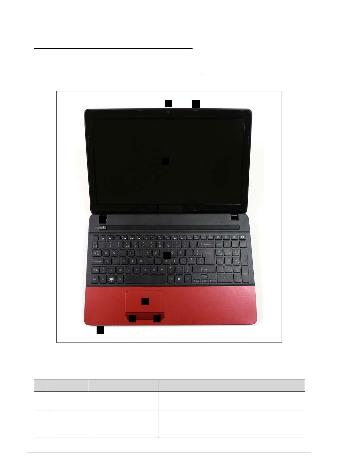
Top View 0
Figure 1-1. Top View
Table 1-1. Top View
# Icon Item Description
1
2 Display screen Also called Liquid-Crystal Display (LCD), displays
Integrated webcam Web camera for video communication (only for
certain models).
computer output (Configuration may vary by
models).
Hardware Specifications and Configurations 1-9
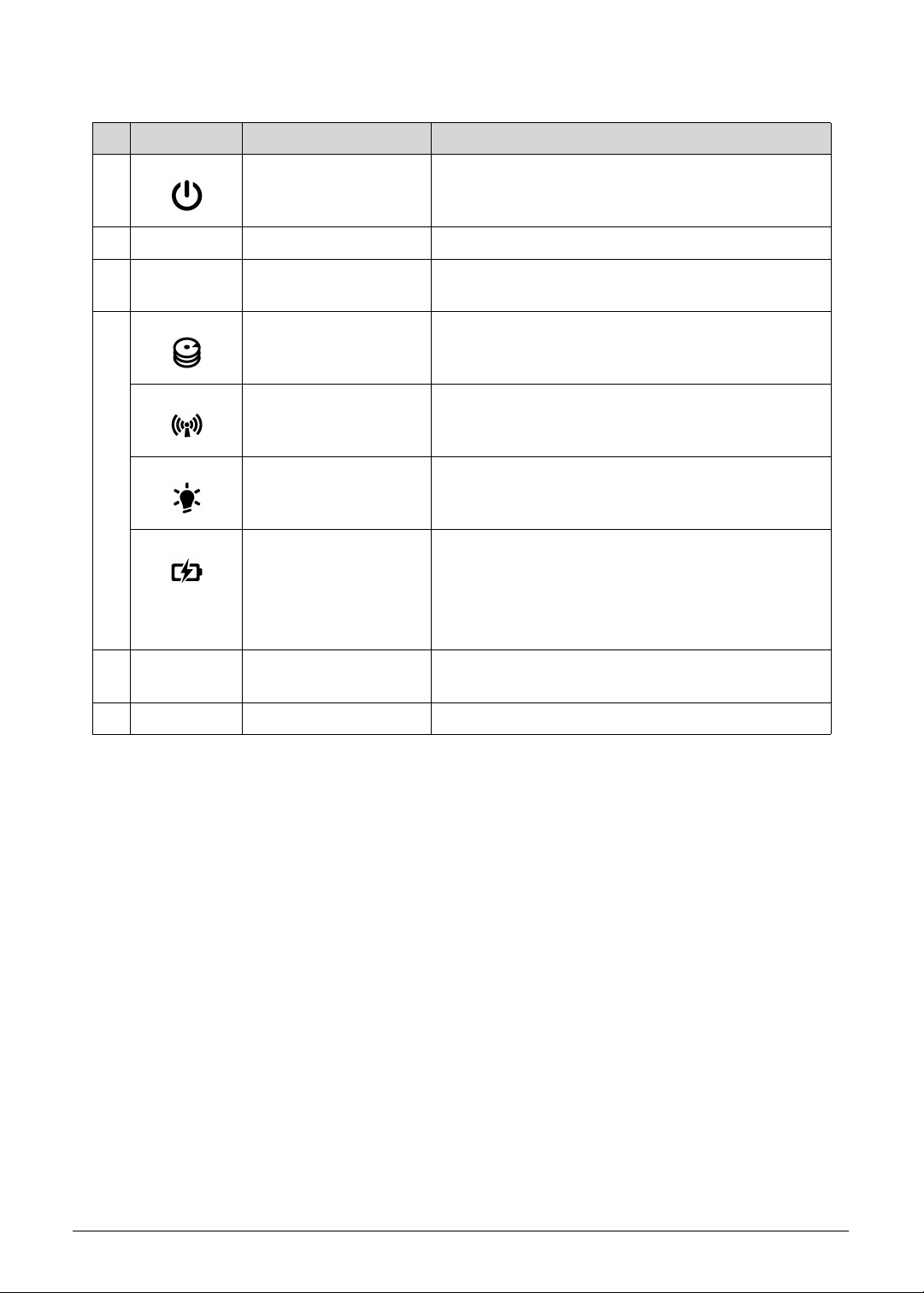
Table 1-1. Top View (Continued)
# Icon Item Description
3 Power button /
indicator
Turns the computer on and off. Indicates the
computer's power status.
4 Keyboard For entering data into your computer.
5 Touchpad Touch-sensitive pointing device which functions
like a computer mouse.
6
HDD indicator Indicates when the hard disk drive is active.
Communication
indicator
Indicates the computer’s wireless connectivity
device status.
Power indicator Indicates the computer's power status.
Battery indicator Indicates the computer's battery status.
Charging: The light shows amber when the
battery is charging.
Fully charged: The light shows blue when in AC
mode.
7 Click buttons (left and
right)
The left and right buttons function like the left and
right mouse buttons.
8 Microphone Internal microphone for sound recording.
1-10 Hardware Specifications and Configurations
Closed Front View 0
NOTE:
NOTE:
21
Figure 1-2. Closed Front View
Table 1-2. Closed Front View
# Icon Item Description
1 Multi-in-1 card reader Accepts Secure Digital (SD), MultiMediaCard
(MMC), Memory Stick PRO (MS PRO), xD-Pictu re
Card (xD).
Push to remove/install the card. Only one card
can operate at any given time.
2
HDD indicator Indicates when the hard disk drive is active.
Communication
indicator
Indicates the computer’s wireless connectivity
device status.
Power indicator Indicates the computer's power status.
Battery indicator Indicates the computer's battery status.
Charging: The light shows amber when the
battery is charging.
Fully charged: The light shows blue when in
AC mode.
The front panel indicators are visible even when the computer cover is closed.
Hardware Specifications and Configurations 1-11
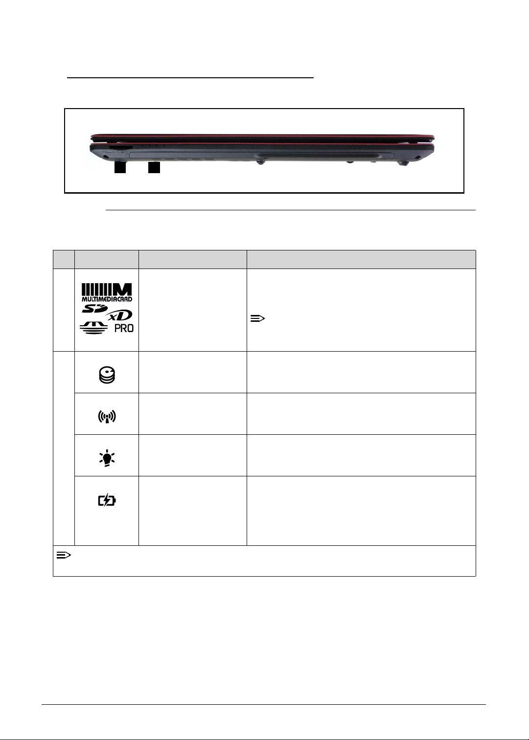
Left View 0
NOTE:
1 2 3 4 5 6
Figure 1-3. Left View
Table 1-3. Left View
# Icon Item Description
1 DC-in jack Connects to an AC adapter.
2 Ethernet (RJ-45) port Connects to an Ethernet 10/100/1000-based
network.
3
4
5
External display
(VGA) port
Connects to a display device (e.g., external
monitor, LCD projector ).
HDMI port Supports high-definition digital video connections.
USB 2.0 port Connects to USB 2.0 devices (e.g., USB mouse,
USB camera).
6
Microphone jack Accepts inputs from external microphones.
Headphones/speaker
jack
Connects to audio devices (e.g., speakers,
headphones).
Supports compatible 3.5 mm headsets with
built-in microphone (e.g. Acer smart handheld
headsets).
1-12 Hardware Specifications and Configurations
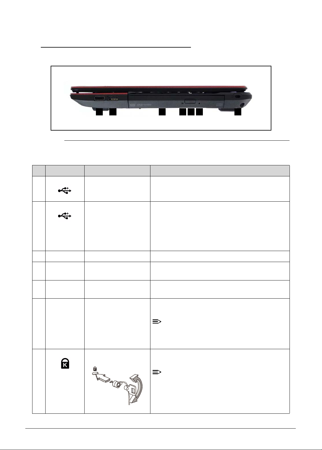
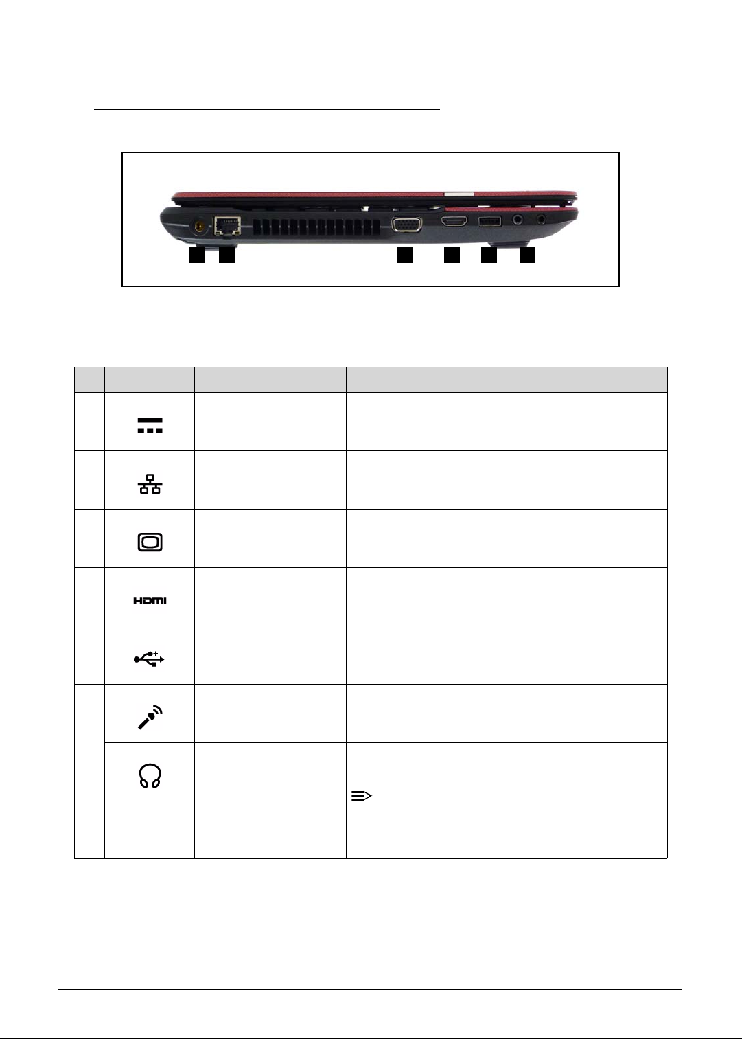
Right View 0
NOTE:
NOTE:
2 3 4 5 6 71
Figure 1-4. Right View
Table 1-4. Right View
# Icon Item Description
1 USB 2.0 ports Connect to USB 2.0 device s (e .g ., USB mo us e,
USB camera).
2 USB2.0/3.0* port Connects to USB devices.
* A USB 3.0 port can be distinguished by its blue
connector (for certain models only).
* Supports the USB 3.0 (SuperSpeed USB)
specification; Devices without USB 3.0 certification
may not be compatible.
3 Optical drive Internal optical drive; accepts CDs or DVDs.
4 Optical drive access
indicator
5 Optical drive eject
button
6 Emergency eject hole Ejects the optical drive tray when the computer is
7 Kensington lock slot Connects to a Kensington-compatible computer
Lights up when the optical drive is active.
Ejects the optical disc from the drive.
turned off.
Insert a paper clip to the emergency eject hole
to eject the optical drive tray when the
computer is off.
security lock.
Wrap the computer security lock cable around
an immovable object such as a table or handle
of a locked drawer. Insert the lock into the
notch and turn the key to secure the lock.
Some keyless models are also available.
Hardware Specifications and Configurations 1-13
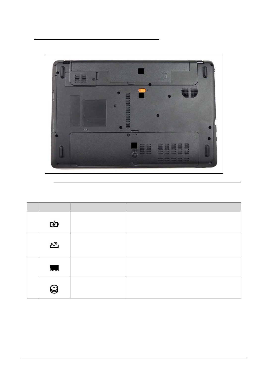
Base View 0
1
2
3
Figure 1-5. Base View
Table 1-5. Base View
# Icon Item Description
1 Battery bay Houses the computer's battery pack.
2 Battery release latch/
lock
3 Memory compartment Houses the computer's main me mory.
Hard disk bay Houses the computer's hard disk (secured with
Releases the battery for removal.
Insert a suitable tool into the latch and
slide to release.
screws).
1-14 Hardware Specifications and Configurations
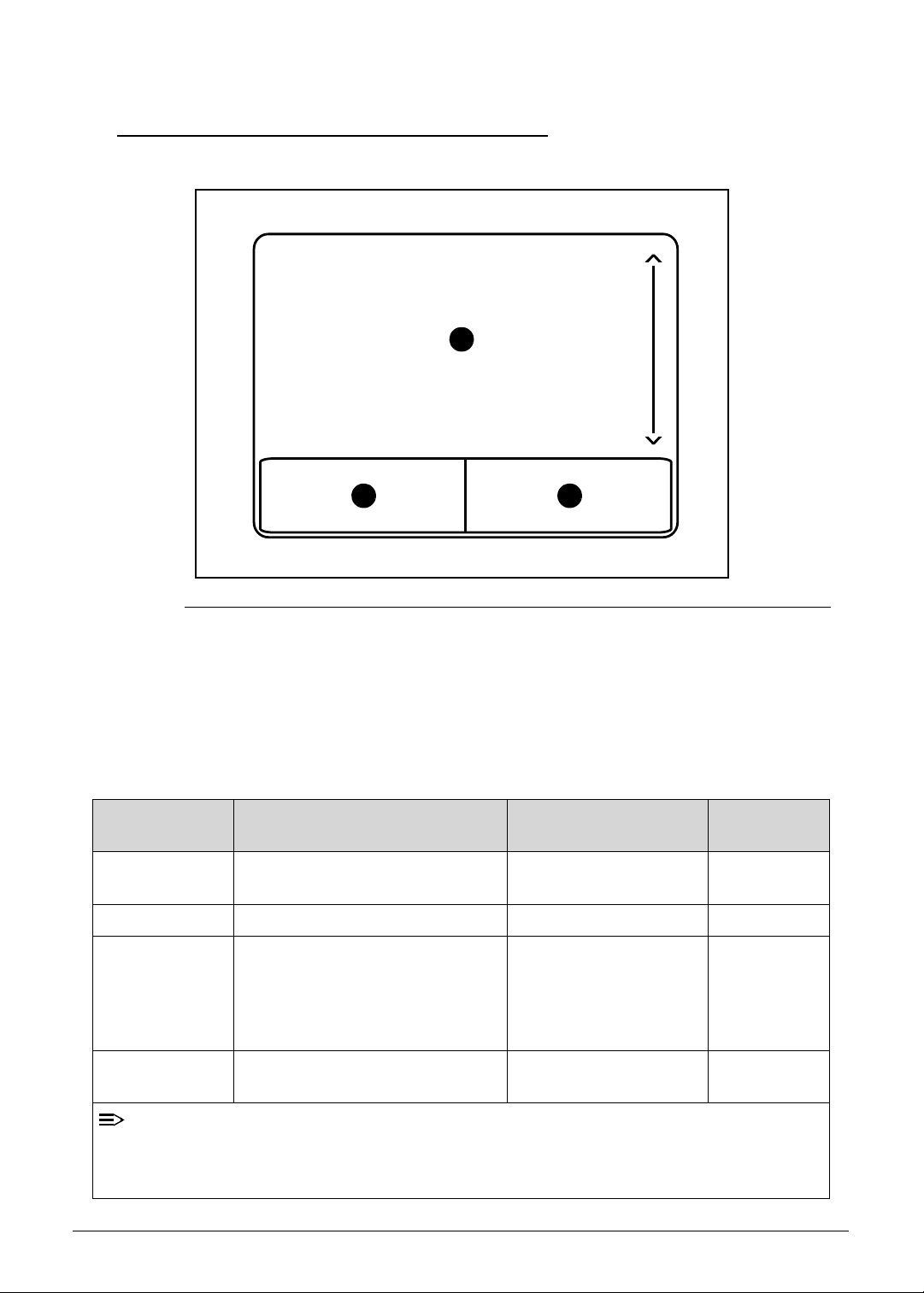
Touchpad Basics 0
NOTE:
1
2
3
Figure 1-6. Touchpad
Move finger across the Touchpad (1) to move the cursor.
Press the left (2) and right (3) buttons located beneath the Touchpad to perform selection and
execution functions. These two buttons are the equivalent of the left and right buttons on a
mouse. Tapping on the Touchpad is the same as clicking the left button.
Table 1-6. Touchpad
Function Main TouchPad (1) Left Button (2) Right Button
Execute Tap twice (at the same speed as
Quickly click twice.
double-clicking a mouse button).
Select Tap once. Click once.
Drag Tap twice (at the same speed as
double-clicking a mouse button);
rest your finger on the TouchPad
Click and hold, then use
finger on the Touchpad
to drag the cursor.
on the second tap and drag the
cursor.
Access context
Click once.
menu
(3)
When using the TouchPad, keep it - and fingers - dry and clean. The TouchPad is sensitive
to finger movement; hence, the lighter the touch, the better the response. Tapping too hard
will not increase the TouchPad’s responsiveness.
Hardware Specifications and Configurations 1-15
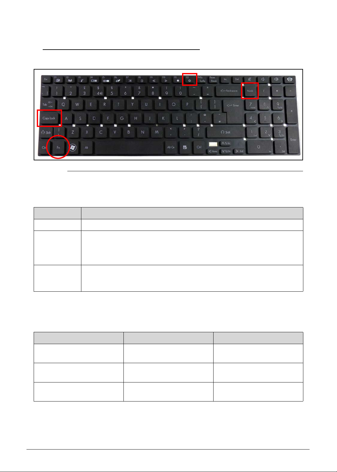
Using the Keyboard 0
Figure 1-7. Keyboard Lock Keys
The keyboard has three lock keys which can be toggled on and off. (Table 1-7)
Table 1-7. Keyboard Lock Keys
Lock key Description
Caps Lock When Caps Lock is on, all alphabetic characters typed are in uppercase.
Num Lock When Num Lock is on, the embedded keypad is in numeric mode. The keys
function as a calculator (complete with the arithmetic operators +, -, *, and /).
Use this mode when doing a lot of numeric data entry. A better solution would
be to connect an external keypad.
Scroll Lock
<Fn> + <F12>
The embedded numeric keypad functions like a desktop numeric keypad. It is indicated by
small characters located on the upper right corner of the key caps. To simplify the keyboard
legend, cursor-control key symbols are not printed on the keys. (Table 1-8)
Table 1-8. Embedded Numeric Keypad
Desired access Num Lock on Num Lock off
Number keys on embedded
keypad
Cursor-control keys on
embedded keypad
Main keyboard keys Hold <Fn> while typing letters
When Scroll Lock is on, the screen moves one line up or down when the up o r
down arrow keys are pressed respectively. Scroll Lock does not work with
some applications.
Type numbers in a normal
manner.
Hold <Shift> while using
cursor-control keys.
on embedded keypad.
Hold <Fn> while using
cursor-control keys.
Type the letters in a normal
manner.
1-16 Hardware Specifications and Configurations
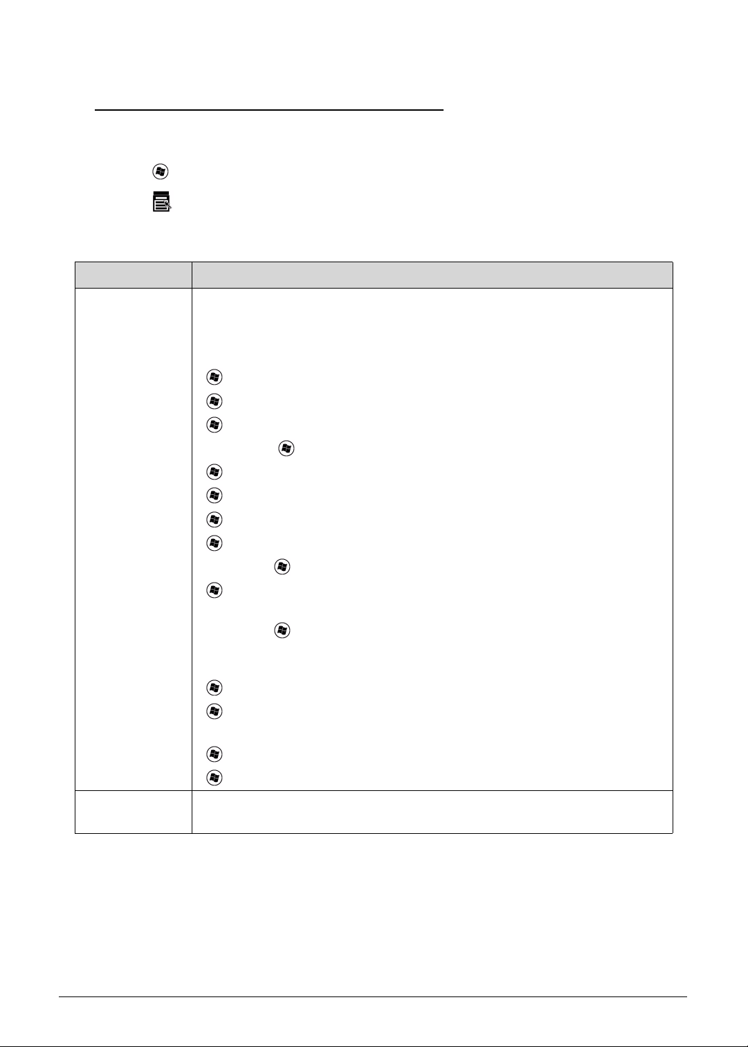
Windows Keys 0
The keyboard has two keys that perform Windows-specific functions.
Windows Logo key
Application key
Table 1-9. Windows Keys
Key Description
Windows Logo
key
Pressed alone, this key has the same ef fect as clicking on the Windows Start
button; it launches the Start menu. It can also be used with other keys to
provide a variety of functions.
Functions supported by Windows XP, Windows Vista, and Windows 7:
< >: Open or close the Start menu
< > + <R>: Open the Run dialog box
< > + <M>: Minimizes all windows
<SHIFT> + < > + M: Undo minimize all windows
< > + <F1>: Show the help window
< > + <E>: Open Windows Explorer
< > + <F>: Search for a file or folder
< > + <D>: Show the desktop
<CTRL> + < > + <F>: Search for computers (if you are on a network)
< > + <L>: Lock yo ur computer (if you are connected to a network
domain), or switch users (if you're not connected to a network domain)
<CTRL> + < > + <TAB>: Moves focus from Start menu, to the Quick
Launch toolbar , to the system tray (use RIGHT ARROW or LEFT ARROW to
move focus to items on the Quick Launch toolbar and the system tray)
< > + <TAB>: Cycle through programs on the taskbar
< > + <BREAK>: Display the System Properties dialog box
Functions supported by Windows XP:
< > + <BREAK>: Show the System Properties dialog box
< > + <U>: Open Ease of Access Center
Application key This key has the same effect as clicking the right mouse button; it opens the
application's context menu.
Hardware Specifications and Configurations 1-17
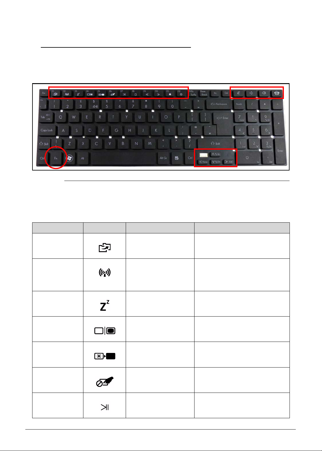
Hot Keys 0
Hot keys or key combinations can be used to access most of the computer's controls like
screen brightness and volume output.
Figure 1-8. Keyboard Hot Keys
To activate hot keys, press and hold the <Fn> key before pressing the other key in the hotkey
combination.
Table 1-10. Keyboard Hot Keys
Hot key Icon Function Description
<Fn> + <F1> Packard Bell
MyBackup
<Fn> + <F2> Communication switch Enables/disables the computer’s
<Fn> + <F3> Sleep Puts the computer in Sleep
<Fn> + <F4> Display toggle Switches display output between
<Fn> + <F5> Screen blank Turns the display screen
<Fn> + <F6> Touchpad toggle Turns the touchpad on and off.
<Fn> + <F7> Play/Pause Plays or pauses media files
Starts Packard Bell MyBackup.
communication devices.
(Communication devices may
vary by configuration.)
mode.
the display screen, external
monitor (if connected) and both.
backlight off to save power. Press
any key to return.
1-18 Hardware Specifications and Configurations
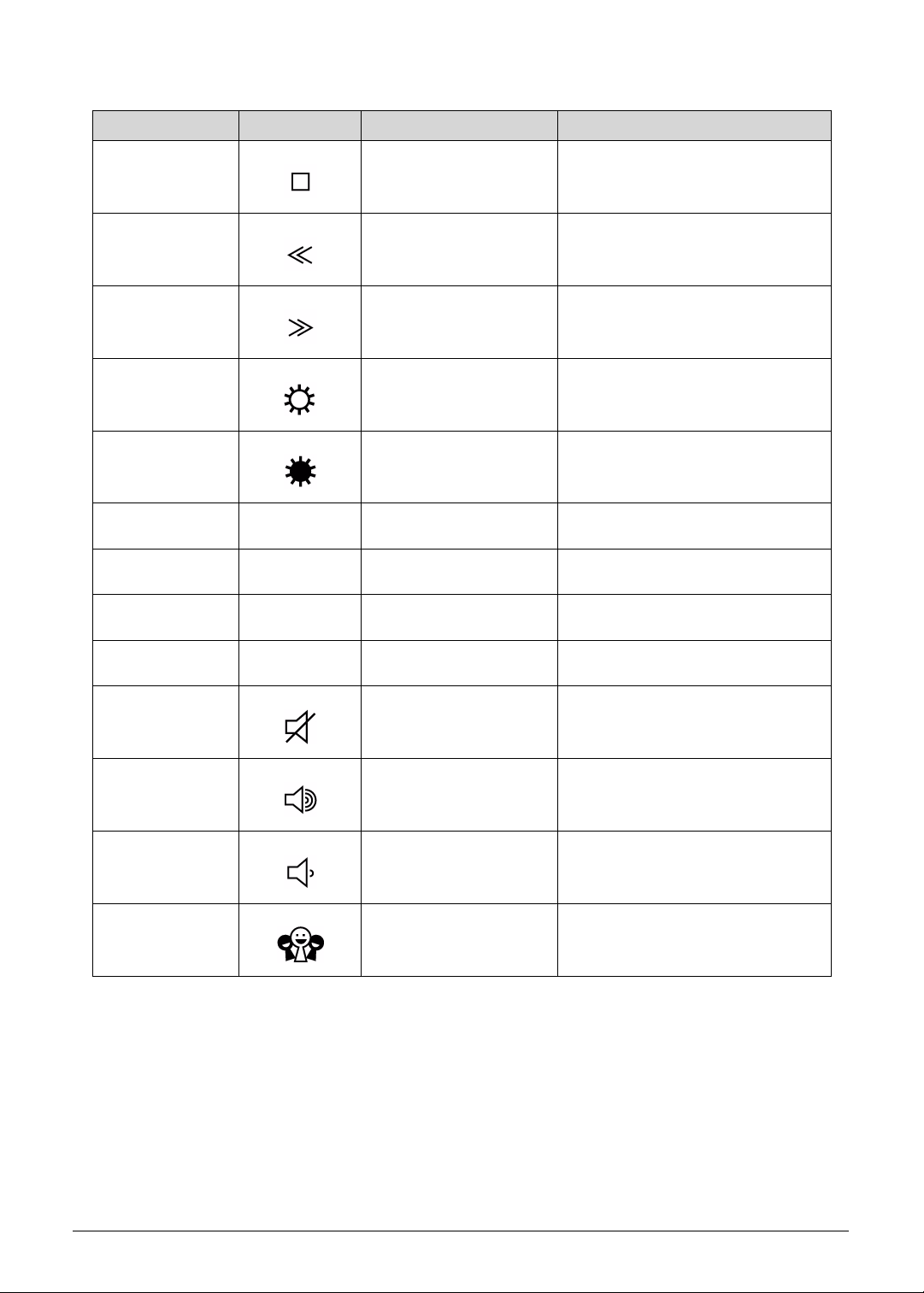
Table 1-10. Keyboard Hot Keys (Continued)
Hot key Icon Function Description
<Fn> + <F8> Stop Stops media file
<Fn> + <F9> Previous Plays the previous media file in
the play sequence
<Fn> + <F10> Next Plays the next media file in the
play sequence
<Fn> + <F11> Brightness up Increases the screen brightness.
<Fn> + <F12> Brightness down Decreases the screen brightness.
<Fn> + <
<Fn> + <
<Fn> + <
<Fn> + <
>
>
>
>
PgUp Page up
PgDn Page down
End End
Home Home
Speaker toggle Turns the speakers on and off.
Volume up Increases audio volume.
Volume down Decreases audio volume.
Social networking Opens the Social Networks
application
Hardware Specifications and Configurations 1-19
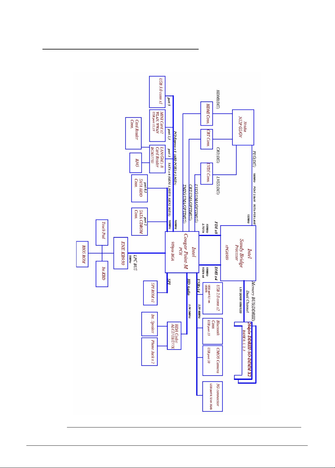
System Block Diagram 0
Figure 1-9. System Block Diagram
1-20 Hardware Specifications and Configurations
 Loading...