

Page 1
EasyNote T5 series Disassembly Manual
NEC Computers International B.V.
EasyNote T5 series
Disassembly Manual
Revi sion: 2.1
Date: M arch 20 05
For Packard Bell
A division of NEC Computers International B.V.
Page 2

Table of contents
Overview........ ......................................... ......................................... .... .......... ... .......... .... .......... .... .......... .......................3
Technician Notes........ .......... ............................... ............................... .............................. ............................... .............3
Disassembly Instructions................. .......... ............................... .............................. ............................... .................... ...3
Reassembly Instructions............................................................. .............................. ............................... ....................3
Required Tools......... ....... ... ... ....... .... ... ....... ... .... ...... .... ... ....... ... .... ....... ... ... ....... .... ... ....... ... .... ....... ... ... ....... .... ... ....... ... ...3
Hazardous Voltage ........ ........... .............................. ............................... ............................... .............................. ..........4
Avoid Electrostatic Discharge............ .......... .... ... ... .... .......... ... .... ... .... ... .......... .... ... .... ... .................... .... ... .... ... .............4
Power Supply Unit ................ .... ... ..................... ... .... ... ... ..................... ... ... .... ... ........... ... ... .... ... .... .......... ... .... ... ... ..........4
Removing the Battery........ ... .... ... ... ........... ... .... ... ... ..................... ... .... ... .... .......... ... .... ... ... .... .......... ... .... ... .... ... .......... ...5
Removing the Hard Disk Drive............................ .... .......... ... .................... .... .................... .... .......... ... ..................... ... ...5
Removing the MDC Modem Module ..................... .... ... .... ... .................... .... ... .... ... .......... .... ... .... ... ... ........... ... ... .... ... ...6
Removing the Keyboard Cover................. ... .... ... ... .... ... .... ... .... ... ... .... ... ... .... ... .... ... ... .... ... .... ... .... ... ... .... ... .... ... ... .... ... ...7
Removing Keyboard ................. .................... ............................... ............................... .............................. ....................7
Removing the Optical drive & Heat plate ..................... ......................................... ......................................... .............8
Removing the Memory Module....... .................... ... ............................... ... ............................... .... .............................. .10
Removing the Wireless Module...... ... ... .... ... .... ... ... .... ... .... ... ... .... ... .... ... .... ... ... .... ... .... ... ... .... ... .... ... ... .... ....... ... .... ... ... .10
Removing Heat Sink & CPU .......................................................... .... .......... ... ..................... ... ..................... ... .......... .11
Removing the LCD Module.................................... .... ............................... ... .............................. .... ............................12
Removing the LCD Penal............ ..................... ... ............................... ... ............................... ... ............................... ... .14
Removing the Top Cover ............ .... ... ... .... ... .... ... ... .... ... .... ... ... ....... .... ... .... ... ... .... ... .... ... ... .... ... .... ... .... ... ... .... ... ... .... ... .16
Removing the Touch Pad................ ... ... .... ... .... ... ... .... ... .... ... ... .... ... .... ... .... ... ... .... ... .... ... ... .... ... .... ... .... ... ... .... ... ... .... ... .18
Removing the DC/DC Board................. .... .............................. .... .............................. .... ............................... ... ...........19
Removing the Main Board........... ..................... ... ............................... ... ............................... ... ............................... ... .20
DIP Switch Setting.......... ... ... ..................... ... .... ... .... .................... ... .... ... ... ........... ... .... ... ... .... .......... ... .... ... .... ..............22
Screws........ ... ........... ... .... ... ... ........... ... ... .... ... .... .......... ... .... ... .... ... .......... ... .... ... .... .......... ... .... ... .... ... .......... .... ... ... .... ....23
Notice.......... ... .... ... .......... .... ... .... ... .......... .... ... .... ... ... ........... ... ... .... ... ..................... ... .... ... ... ..................... ... .... ... ... ........24
Packard Bell EasyNote T5 Disassembly Manual
Page 2
Page 3

Overview
This docu ment cont ai ns ste p- by -st ep di sass embly ins truct i ons for the EasyNote T5 chas si s. The i nst ructions are
illustr at ed w here necessary wi t h images of the part that is bei ng removed or disasse mble d. Further more, the screw s
that are r emoved are s hown nex t to the i mage of the parts t hemselv es.
Packar d Bell r eserves the ri ght to make cha ng es t o the Easy N ote T5 chassi s without noti ce.
Technician Notes
Only tech ni cians authorized by NEC Computers I nt ern a ti onal B.V. shoul d att empt t o repair this equip ment. Al l
troubleshooting and repai r proc ed ures are det ailed to allow on ly sub as sembly/module leve l rep air. Becaus e of t he
complex ity of the i ndi vidual boards an d s ubasse mblies, no one sh ou ld attempt to ma ke repairs at t he c omponent
level or to ma k e modificati ons to any pri nt ed wiring board. Impro per re pairs can cre at e a saf et y hazar d. Any
indicat i on of co mpone nt rep la ce me nt or print e d wiring board modificat i ons may v oid any warranty or exchange
allowances.
Disassembly Instructions
When disas s e mbli n g the system uni t, follow these g en er a l rules :
n Do not disassemble the system int o parts t hat are smaller than those specified in the instructi ons.
n Label all re moved conn e cto rs. Note wh er e t he c onn ector goes a n d i n what position it was installed.
n Turn off the pow er an d di scon nect all p ow er an d all o pti ons.
Reassembly Instr uctions
Reasse mbly i s the reverse of the di sass e mbly pr o cess. Use car e to ensu re t hat all cab les an d screws are ret ur ned
to their pro per positions. Check that no to ols or any loose parts hav e been left i nside th e ch assis. Chec k that
everyt hi ng i s proper ly ins tall e d and ti ght en e d.
Required Tools
All disass e mbly pro ce d ur es can be perf ormed using the f ollow ing tools:
n PH 0x60 Philips screwdriver
n PH 0x40 Philips screwdriver
n 4.0 x 60 Fl at screwdriver
n 2.0 x 30 Fl at screwdriver
n SW5,0 Spacer screwdriver
n Small tweezers
Packard Bell EasyNote T5 Disassembly Manual
Page 3
Page 4

Hazardous Vo ltage
There i s hazardous volt age pr es e nt inside the computer
when it is connected to an AC supply, even when the
computer’s power switch is off. Ex posur e to haz ar do us
voltage c ould cause p ersonal injury. To av oid risk of injury,
contact an Authori z ed Service Provi der f or pr oper
(un)ins t allation of optional hardware devices.
Avoid Electrostatic Discharge
Electro st at i c electricity can easi ly damage ci r cui t cards a nd
integr ate d cir cui ts (I Cs). To reduc e ris k of dama ge, stor e
them in prot ective pa ckaging whenever they are not
installed in your system.
Add-i n cards can be ex t re mely sensitive to ES D and always
requi re c ar ef ul ha ndling. Af t er r emoving the card fr om the
computer, plac e the card flat on a gro und ed, st at i c-fre e
surface, co mpo ne nt-side up. Use a con du ctiv e foa m pad if
availab le, but not t he card w ra pper. Do not slide the card
over any surfac e.
WA RNING
Ensure that the computer is disconnected from
its power source and from all
telecommu nications links, net w orks, or mod em
lines whenever the chass i s cover is removed.
Do not operate th e co mput er wi t h the cover
removed.
AVERTISSEMENT
Assure z-v ous que l e système est dé br anché de
son ali me nt ation ainsi que de tout es les
liais ons de té lécommuni cation, des rése aux, et
des lignes de modem avant d’enlever le cap ot .
Ne pas utiliser le système qua n d le capot est
enlevé.
WA RNUN G
Das System darf weder an eine Stromquelle
angeschlossen sei n noch eine Verbindu ng mit
einer Tele k ommu nikati ons ei nrichtung, ei nem
Netzwer k oder einer Mo de m-L ei t ung habe n,
wenn di e Geh äuseabde ckung entf ernt w ird.
Nehmen Si e das Syst em ni cht ohne di e
Abdeckung in Betrieb.
Before yo u install or remove me mory modules, vi de o
memory, disk drives, circuit cards or other devices, protect
them from static electricity. To do so, make sure your
computer’s power sw itch is OFF. Then, un plug the
computer’s AC pow er cord. Befor e pi c ki ng up the device you
(un)ins tall, you should w e ar a n ant i - static wris t wrap
(avai lable at ele ctr onic supply st ores). Be sure t o co nn ect
the wri st w rap to an u np ainted meta l portion of the co mputer
chassis . As an alter native, y ou can di ssipate electr ost atic
build-up by touchi ng an u np ainted meta l portion of t he
computer chas si s wit h one hand. The n touch th e dev i ce y ou
are (un)i ns t alling with the other ha n d, and mai nt ain
continuous cont act wit h it until it is (un)installed in the
comput er.
Power Supply Unit
Under no ci rcumstan ces sh ou ld y ou at tempt to disassemble
the power supply. The power supply cont ains no userservi ceable part s. I nsi de t he power s up ply are h az ar dous
voltages that can cause s erious personal injury . Alw ays
return a d efective power su pp ly t o your de a ler.
ADVERTEN CIA
Asegúr es e de q ue c ada vez que s e quite la
cubierta del chasis, el si stema hay a s ido
desconectado de la red de alimentación y de
todos lo enlaces de telecomunicaci ones, de re d
y de líneas de módem. No ponga en
funciona mie nt o el si stema mientr as la cubi erta
esté quitad a.
WAARSCHUWING
Zorg er voor dat a lle v erbindingen v an en naar
de computer (st r oom, modem netwerk, etc )
verbroken word en voordat de behui zi ng
geopend wordt. Zet de computer nooit aan als
de behuizi ng ge ope nd i s.
AVVERTENZA
Prima di r imu ove re il coperchio del tel aio,
assicurarsi che il sistema sia scollegato
dall’alimentazi one, da tutti i collegame nti di
comuni ca zione, reti o linee di mode m. N on
avviare i l si stema senza aver prima messo a
posto il coperchio
Packard Bell EasyNote T5 Disassembly Manual
Page 4
Page 5
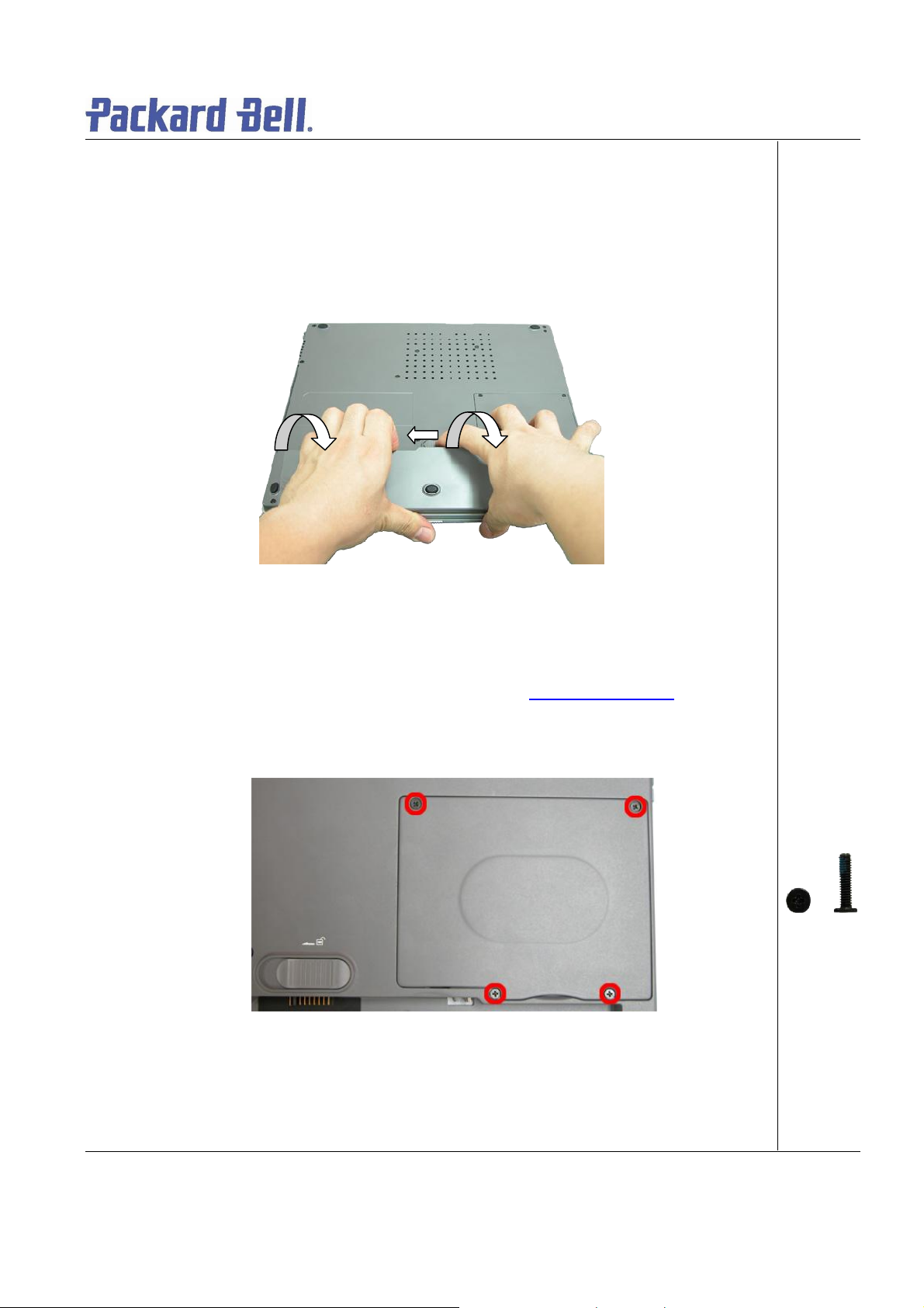
Removing the Battery
Perfor m t he f ollowing st eps t o r emov e the battery:
1. Make sure to power off the EasyNote T5 first.
2. Turn the unit upside down.
3. Unlock the battery and slide it out of its place as the arrow shows in Fig. 1
Fig. 1 Removing the b attery
Removing the Har d Disk Drive
To remove t he hard di s k dri ve, fir st re move th e battery (see Removing the Batt ery
the foll owing steps:
1. Remove the screws as shown in Fig. 2
Fig. 2 Removing the Hard disk drive cover
), then perform
M2.5x11 Black
2. Lift up the hard disk drive and disconnect it as shown in Fig. 3
Packard Bell EasyNote T5 Disassembly Manual
Page 5
Page 6
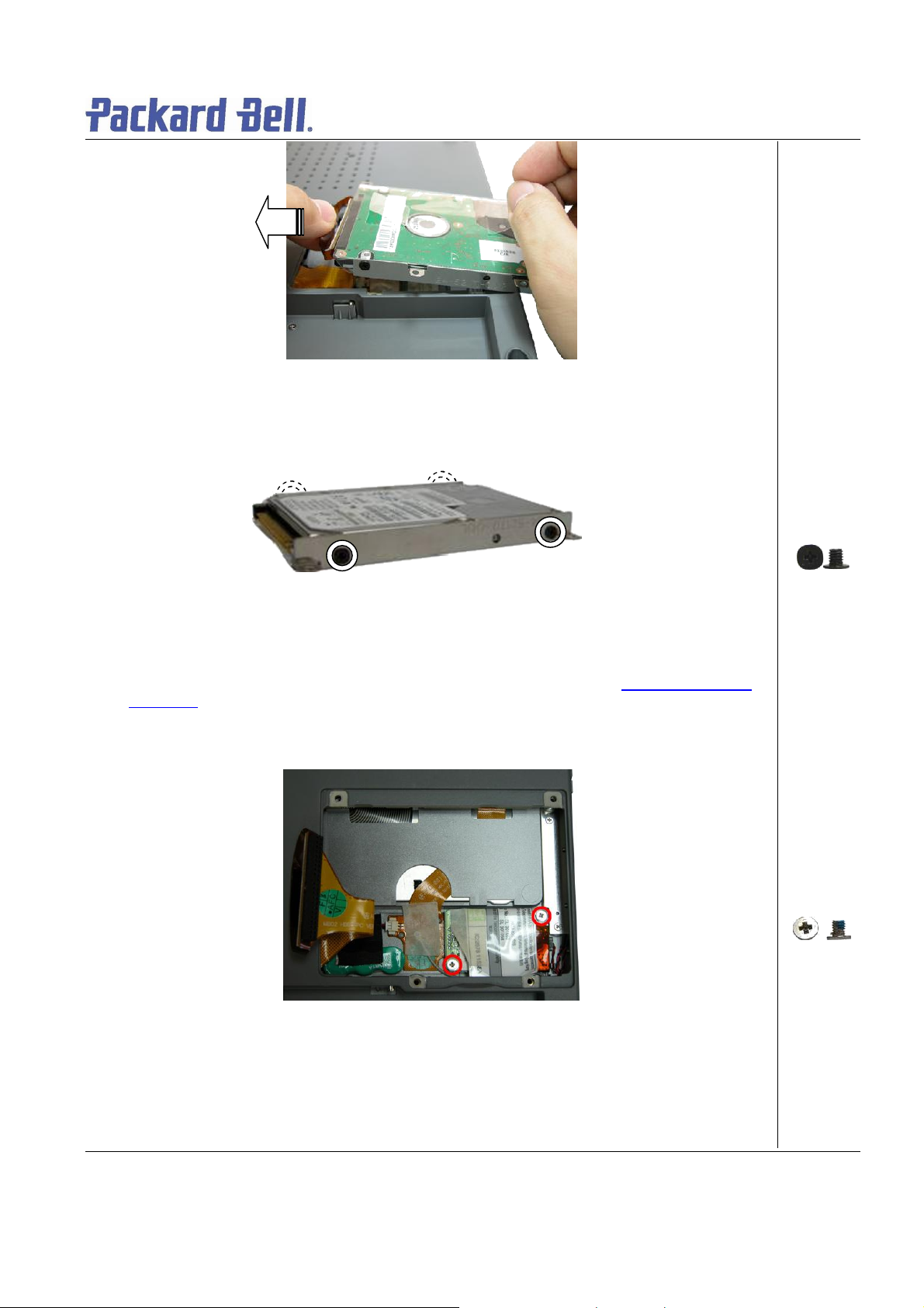
Fig. 3 Disconnecti n g the har d dis k dri ve
3. Unscrew the four screws on both sides of the hard disk drive as shown in Fig. 4
Fig. 4 Unscrewi n g the har d dis k dr i ve br a ck et screws
Removing the MDC Modem Module
To remove t he M D Cmod e m mo d ule, fi r st re move the hard dis k driv e ( se e Removing the Hard
Disk Drive), then perform the following steps:
1. Remove the screw shown in F ig. 5
M3x4 Black
Fig. 5 Removing the scr ew s on t h e MCD m odem
2. Careful ly lift up MDC m odem module.
3. Disconnect the cable attached to the MDC m odem and put the modem aside.
Packard Bell EasyNote T5 Disassembly Manual
M2.5x3.5 Sliver
Page 6
Page 7

Removing the Keyboard Cover
To remov e t he Keybo ard Cover , first re move t he battery (see Removing the Bat t ery), then
perform t he following s t e ps:
1. Remove the screw as shown in Fig. 6
Fig. 6 Rem oving Keyboar d C ov er screws
M2x15 Black
2. Remove the Ke yboard Cover as shown in Fig. 7
Fig. 7 Removing the K eyboard Cover
Removing the Keyboard
To remov e t he Keyboard mo dule, first remove the keyboar d c ov er (see Removing keybo ard
cover), the n perf or m the fo llowing steps:
Packard Bell EasyNote T5 Disassembly Manual
Page 7
Page 8
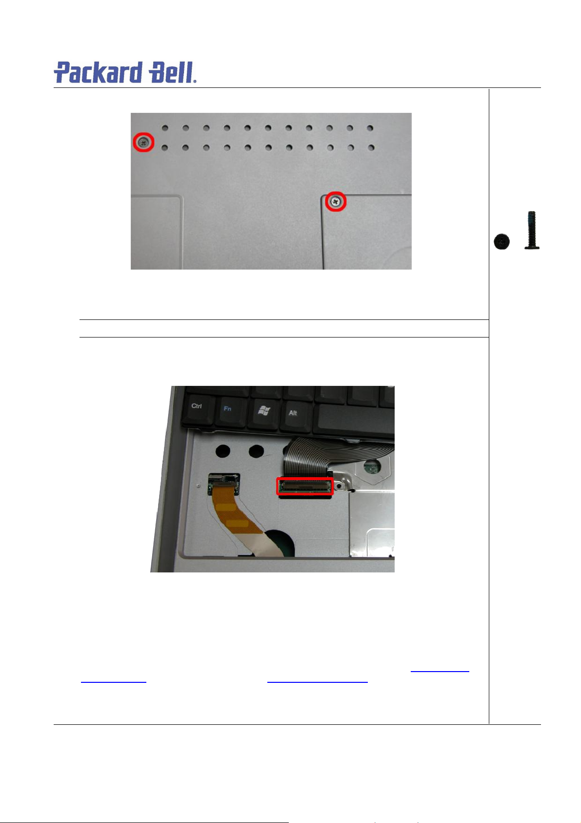
1. Remove the screws as shown in Fig. 8
A
Fig. 8 Removing the screws hol ding the keyboar d
Not e: The scre w “A” locate d on the hard disk slot cov e r hol ds the hard di s k dri ve and the keyboard.
2. Carefully lift up the keyboard.
3. Release the keyboard F PC cable as shown in Fig. 9 and put the keyboard a side
M2.5x11 Black
Fig. 9 Removing the keyboard FPC cable
Removing the Optical drive & Heat plate
To remove the optical dri ve & heat plat e, fi r st re move th e keyb o ar d cover (se e Removing the
keyboard cover), re move the keyboard (seeRemovi ng the keyboard) t hen perfor m t he f ollowing
steps:
1. Remove the screw as shown in Fig. 10
Packard Bell EasyNote T5 Disassembly Manual
Page 8
Page 9

Fig. 10 Removing t he screws on H eat Pl ate
A
Not e: If you want to disassemble the Optical Drive, you are required to release Screw “A” only.
2. Push the Optical Drive module ou t from the base unit as shown in Fig. 11
M2.3 x 6 Sliver
Fig. 11 Pushing Optical Drive module o ut from base unit
3. Carefully remove the heat plate from the base unit.
Packard Bell EasyNote T5 Disassembly Manual
Page 9
Page 10

Fig. 12 Removing Heat plate from base unit
Note: When assembling the heat plate , mak e sure t hat these thre e hocks on the heat pl ate are properly
inserted into the openings located on the top cover.
Removing the Memory Module
To remove t he me mory module, first remov e the Key b o ar d cover (see Removing the key boar d
cover), remove the keybo ard (see Removing th e keyb oar d), remove heat plate (s ee Removing
heat plate) then perform the following steps:
1. Unclip memory module as s h own in Fig. 13
Fig. 13 Removing the memory module
2. Remove the Memory Module from its slot and put it aside.
Removing the Wireless Module
To remove the Wir eles s M o dule, fi r st re move th e keyb o ar d cover (see Removing the key boar d
cover), remove the keybo ard (see Removing th e keyb oar d), remove the heat plate (see
Packard Bell EasyNote T5 Disassembly Manual
Page 10
Page 11

Removi ng heat plat e), t hen p erform the foll owing steps:
1. Disconnect the wireless antenna connectors as shown in Fig. 14
Fig. 14 Disconnecting the wireless a ntenna
Not e: You mi ght consider disconnecting the touch pad flat cable before remov ing the wireless mod ul e .
2. Unclip the wireless modul e to release it from slot and put it aside.
Removing Heat Sink & CPU
To remov e t he Heat Sink & CPU, fi rst re move the Keyboard C ov er ( see Remo ving the keyboard
cover), remove the keybo ard (see Removing th e keyb oar d), remove optical drive & heat plate
(see Removing optical driv e & heat plate
) then perfor m the foll owi ng ste ps:
1. Release the screws on the heat sink in descending order (4à3à2à1 ) as s hown in Fig. 1 5
Fi g. 15 Releasing the heat sin k scr ew s
Not e:When a s sembling the hea t s ink, tighten t he heat sink screws according to the ascending or der
(1à2à3à4). This is to ensur e a well distribute d pres sure over t he CPU and to prevent damaging the CPU
M2.5x11 Black
2. Carefully remove the heat sink from the CPU socket as shown in Fig. 16
Packard Bell EasyNote T5 Disassembly Manual
Page 11
Page 12

Fig. 16 Removing the heat sink
ck et; carefully lif t up the CPU and
3. Use flat screws driver to relea se the CPU from the CPU so
put it in a safe place.
Removing the LCD Module
To remove the L CD Mod ule, fi r st remov e the Keyboard Cover (see Removing the keyboard
cover) t hen remove the keyboard (see Removi ng the keyb oard) and di sconn e ct the wi reless
antenna cables (see Removing the Wir eles s Mod ul e
Fig. 17 Releasing the CPU
).
Packard Bell EasyNote T5 Disassembly Manual
Page 12
Page 13

1. Unscrew th e two LCD connector screws and also, disconnect the speaker connector as
shown i n Fig. 18
Fig. 18 Discon ne ct ing th e LCD & speak er c on ne ctors
2. Remove the LCD cable cover with a small flat screws driver as shown in Fig. 19 .
M2.5x11 Black
Fi g. 19 Removing t he LCD c able Cover
3. Release the screws at rear side of the unit a s shown in Fig. 20
Fig. 20 LCD hinge s crews at th e r ear
Packard Bell EasyNote T5 Disassembly Manual
M2x6 Black
Page 13
Page 14

4. U n screw the two screws located on the bottom of the unit as s ho wn in Fig. 21
Fig. 21 LCD hinge scr ew s at the bot t om
5. C areful l y lift the LCD module out of the system and pu t it aside .
M2x6 Black
Removing the LCD Panel
To remov e t he LCD Pa nel, first remove the LCD Module ( se eRemoving the LCD Module
perform t he following s t e ps:
1. Unscrew all screws shown in Fig. 2 2
Packard Bell EasyNote T5 Disassembly Manual
), then
Page 14
Page 15

Fig. 22 Screws on the LCD Module
AAA
A
B
B
2. Relase the LCD Bezel carefully and put it a side as shown in Fig. 23
A = M2x3.5
Silver
B= M2x5
Silver
Fig. 23 Rem ovin g the LC D Bez el
3. Unscrew all screws encircled in Fig. 24 disconnect the inverter b oard and put it a side.
Packard Bell EasyNote T5 Disassembly Manual
Page 15
Page 16

M2x5 Silver
Fig. 24 Removing the inverter bo ard screws
4. Carefully lift up LCD panel and disconnect the LCD cable from the penal.
5. Remove the screws at both sides of the LCD panel in order to release the LCD hinges as
shown in Fig. 25 .
Fig. 25 Removing the LCD Pan el hinges
Removing the Top Cover
M2x 3 .5 Sil ver
Packard Bell EasyNote T5 Disassembly Manual
Page 16
Page 17

To remove the Top C over, fi r st remov e the Key boar d Cover (see Removing the keyboard cover
),
Re movin g t he
ABAAB
remove the keyboard (see Removing the keyboard), remove the LC D modu le (see
LCD Module) then perfor m the fo llowing steps:
1. Disconnect the MIC connector on the DC/DC board.
2. Release all screws shown in Fig. 26
A = M2x6
Black
B = M2.5x12.5
Silver
Fig. 26 Removing the Top cover screws
3. Flip over the unit and remove the sc rews as shown in Fig. 27
Fig. 27 Removi ng t h e To p cover screws on the bottom of t he s ystem
A = M2x15
Black
B = M2 .5x11
Black
4. Rem ove all screws in th e battery compartment as shown in Fig. 28
Packard Bell EasyNote T5 Disassembly Manual
M2x3 Sliver
Page 17
Page 18

Fig. 28 Bat ter y C o mpar t ment
5. Carefully lift up and release the top cover and put it as ide.
Fig. 29 Removi ng t h e top co ver
Not e: Reme mber t o disconnect the t ou ch pa d ca ble before lif ti n g up the t o p c over. On the VGA c on ne ctor
area us e extra care to rel e a s e t he t op c over.
Removing the Touch Pad
To remov e t he Touch Pad, first remove the Top Cov er (see Removing the Top Cover
perform t he following s t e ps:
Packard Bell EasyNote T5 Disassembly Manual
), then
Page 18
Page 19

1. On the other sid e of the top cover un screw the two screws on the Touch Pad assem bly as
shown in Fig. 30 and re move the Touch Pad assy f ro m t he palm rest.
M2x 3 .5 Sil ver
Fig. 30 Touch P ad A ssembly
Removing the DC/DC Board
To remove t he D C/ DC bo ar d, fi rst r emove t he Top Cover (see Removing the To p Cov er
perform t he following s t e ps:
), then
1. R emo ve the screw on the D C/DC board as sh own in F ig . 31
Packard Bell EasyNote T5 Disassembly Manual
Page 19
Page 20

Fi g. 31 DC/DC B oar d
2. Carefully remove the DC/DC board as shown in Fig. 32 and put it aside.
M2.5x11 Black
Fig. 32 Removing th e DC/ DC Board
Removing the Main Board
To remov e t he Main boar d, first open the Top Cover (s ee Removing the Top Cover), remove
DC/DC b oard (seeRemovi ng DC/ D C b oar d
1. Remove the screws holding the main board in place as shown in Fig. 33
Packard Bell EasyNote T5 Disassembly Manual
) then perf o rm the following steps:
Page 20
Page 21

A = M2x5
B
A
A
Silver
B = M2.5x8
Silver
Fig. 33 Removi ng t h e mai n b oard screws
2. D iscon nect the VGA connector from the base a s shown in Fig. 34
Fig. 34 Disconnecting the VGA connector
3. Lift the main board out of the system and put it aside (Fig. 35 ).
M2.5x10 silver
Packard Bell EasyNote T5 Disassembly Manual
Page 21
Page 22

DIP Switch Settings
Dip Switch
Description
Seeting
Keyboard
Keyboard
ON : Enable
Password ov erride.
ON: Overr ide
OFF
OFF
US Keyboard
Fig. 35 Removing M ain Board
Bit1
Bit2
Bit3
Select1
Select2
Reserved Reserved
BIOS CrisisBit4
DVDSELBit5
PasswordBit6
Refer to the below table
Refer to the below table
OFF: Normal (Default)
ON : connect to GND
OFF : NC
OFF: Available (factory setting)
Bit 1 Bit 2 Keyboard code
ON OFF JP Keyboard
OFF ON Reserved
ON ON UK Keyboard
Packard Bell EasyNote T5 Disassembly Manual
Page 22
Page 23

Screws
M2.5x5.6 Silver M2.5x3.5 Silver M2.5x8 Sliver M2.5x10 Silver
M2.5x11 Black M2.5x12.5 Silver M2.5x15 Black M2x3 Sliver
M2x6 Black M3x4 Black M2.5x5 Sliver
Packard Bell EasyNote T5 Disassembly Manual
Page 23
Page 24

Disclaimer
The information in this gui de i s subject to change without noti c e.
This guid e cont ai ns i nformation pr otected by copyright. No part of thi s guide may be ph ot o co pi ed or repr o d uc ed in
any form or by any means wi t hout pri or wri t t en cons ent fro m NE C Co mputers I nternat i onal BV.
NEC COMPUTERS I NTERNATIONAL BV SHALL NOT B E LI A B LE FOR TECHNICAL O R E DITORIAL ER RORS
OR OMISSIONS CO NTAINED HEREIN; NOR FOR INCI DE NTAL OR CONSEQUENTIAL DAMAGES RES ULTING
FROM THE FURNISHING, PERFORMANCE, OR USE OF THIS MATERIAL.
Copyright © 2005 NEC Computers International BV. All rights reserved.
NEC is a tr ademark of NE C C omputers International BV.
The names of actua l co mpanies and products ment i one d her ei n may be tr ad emar ks an d/ or r egistered trademarks
of their respective ow ners.
Revision History:
Revision Date By For
1.0 September 2003 Allen Koay ( S&S Penang) NEC Comput er s Malaysi a*
2.0 September 2003 Dean Egbert s (S&S Wijchen) Pa c kard B e l l Eur ope*
2.1 March 2005 Dean Egberts (S&S) P ackar d B e ll Europe*
* A division of NEC Computers International B.V.
Packard Bell EasyNote T5 Disassembly Manual
Page 24
 Loading...