

Page 1
Disassembly Manual EasyNote J2 series
Disassembly Manual
T19
version change by date
0.1 Copied text from written notes DE 18-10-2005
0.2 Added photos & corrected layout DE 19-10-2005
Page 1 of 15
Page 2
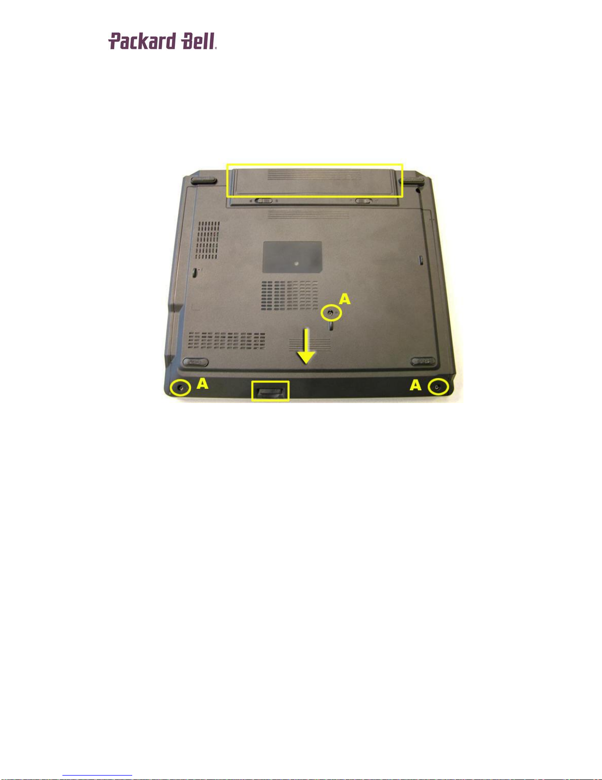
Battery & Dummy Car ds
1. Remove the Battery.
2. Take out the (dummy) Memory Card.
3. Take out the (dummy) PCMCIA Card.
Disassembly Manual EasyNote J2 series
Figure 1
Bottom Cover
1. Remove 3 x A screws from the Bottom Cover (fig. 1).
2. Slide out the Bottom Cover as indicated.
Page 2 of 15
Page 3
Disassembly Manual EasyNote J2 series
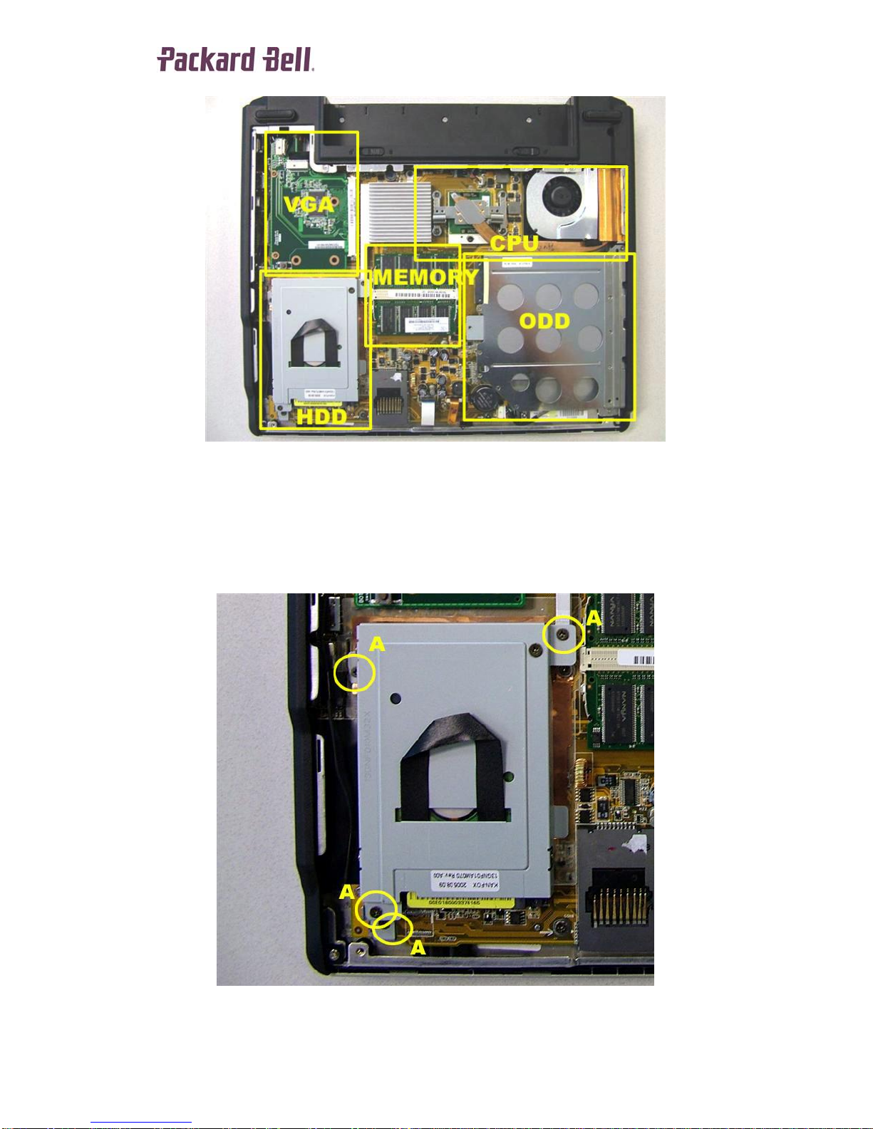
Figure 2
Hard Disk Drive
1. Remove 3 x A screws.
2. Slide out the Hard Disk Dr ive (HDD) Assemb ly.
3. Remove 1 x A screw from the HDD Mounting Bracket and remove it.
Figure 3
Page 3 of 15
Page 4
Disassembly Manual EasyNote J2 series
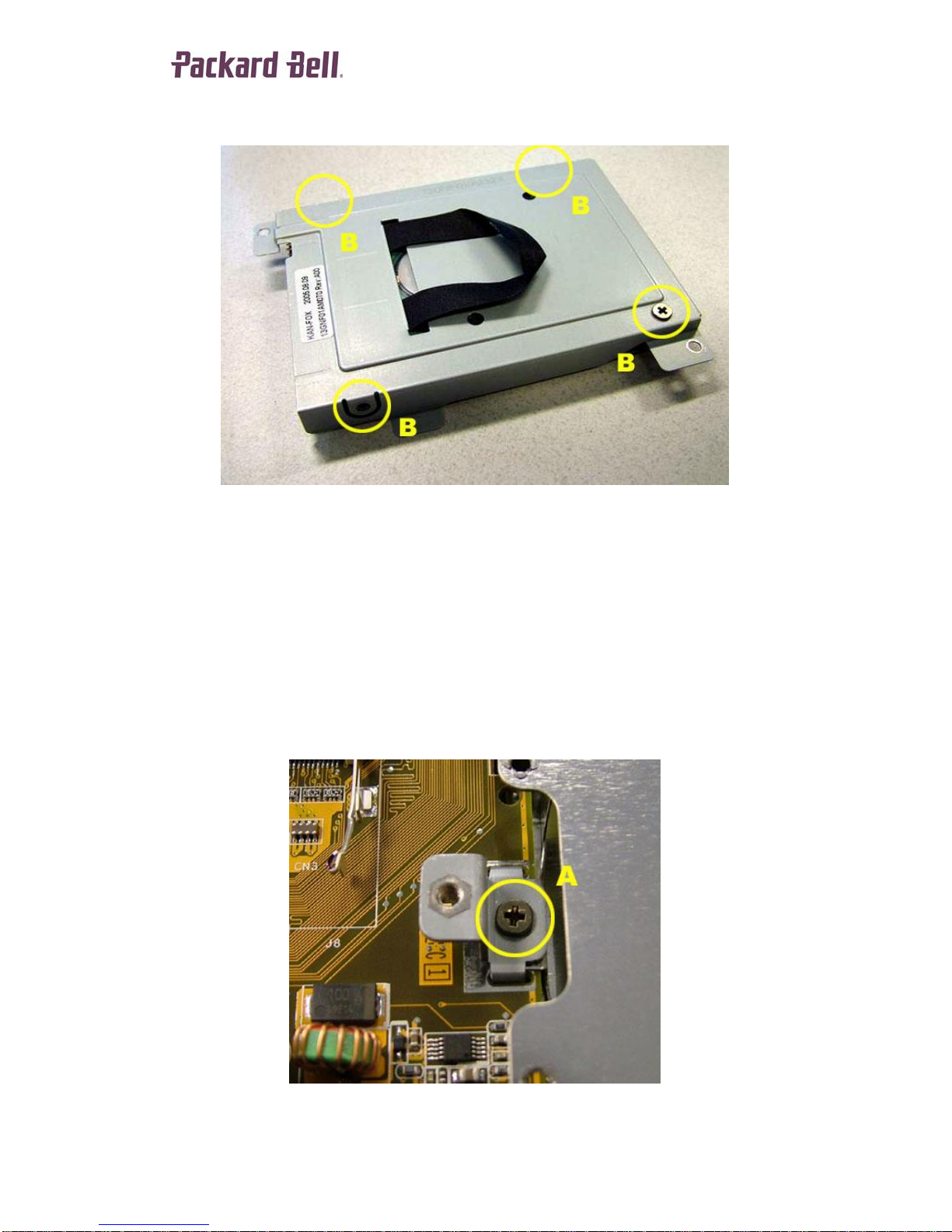
4. Remove 4 x B screws from the HDD Bracket and remove it.
Figure 4
Memory Module
1. Remove the Memory DIMM(s) from the Memory Slot(s).
Optical Disk Drive
1. Push out the Optical Disk Drive (ODD).
2. Remove 1 x A screw from the ODD Mounting Bracket and remove it.
Figure 5
Page 4 of 15
Page 5
Disassembly Manual EasyNote J2 series
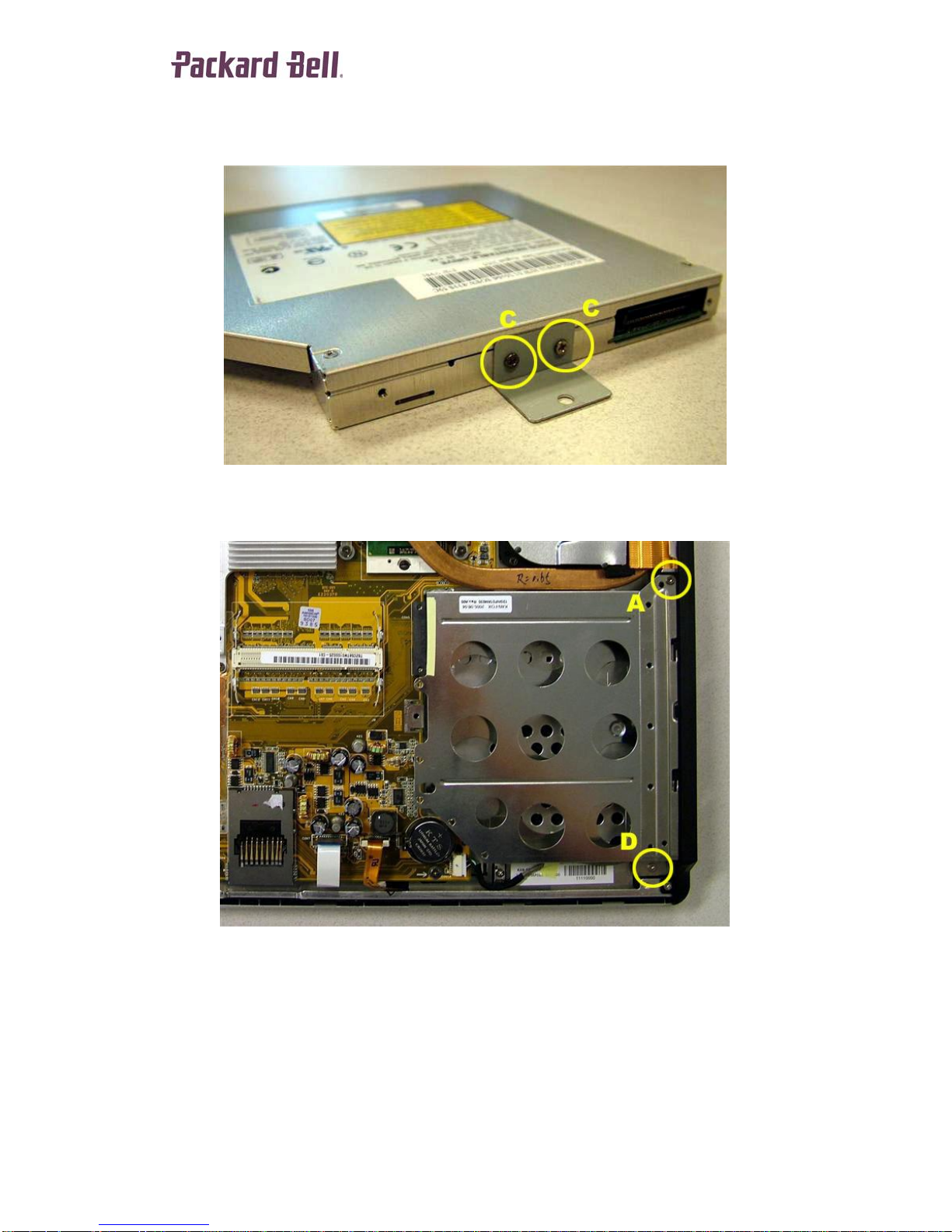
3. Remove 2 x C screws from the ODD Bracket and remove it from the ODD.
Figure 6
4. Remove 1 x A screw and 1 x D screw from the ODD Frame and remove it.
CPU Module
1. Disconnect the CPU Fan Cable.
2. Remove 2 x A screws from the CPU Fan Assembly and remove it.
3. Remove 4 x A screws from the CPU Heatsink and remove it.
4. Unlock the CPU Module and remove it.
Figure 7
Page 5 of 15
Page 6

Disassembly Manual EasyNote J2 series
Figure 8
Video Graphics Accelerator Board
1. Remove 2 x C screws from the Video Graphics Accelerator (VGA) Board.
2. Remo ve the VGA B oard.
3. Disconnect the VGA Connectors from the VGA Board.
Figure 9
Keyboard
1. Push up the 3 Clips at the top of the Keyboard to unlock it.
2. Flip over the Keyboard and disconnect the Keyboard Flatcable.
Page 6 of 15
Page 7

Disassembly Manual EasyNote J2 series
Figure 10
Mainboard
1. Remove 2 x E screws from the Rear of the unit.
2. Remove 2 x A screws from the Battery Connector Bracket and remove it.
Figure 11
3. Remove 2 x F hexbolts from the VGA Connector (right side of unit).
Figure 12
Page 7 of 15
Page 8

Disassembly Manual EasyNote J2 series
4. Remove 2 x A screws from the Chipset Heatsink and remove it.
5. Remove 4 x A screws from the Mainboard.
6. Disconnect the two (2) Flatcables from the Mainboard.
7. Slide the Mainboard out of the Bottom Base Assembly.
Figure 13
Modem
1. Remove 2 x C screws from the Modem.
2. Lift up the Modem and disconnect the Modem Cable.
3. Remove the Modem and Modem Cable.
Figure 14
Page 8 of 15
Page 9

Disassembly Manual EasyNote J2 series
LCD Assembly
1. Push the Hinge Covers In + Up to release, then remove the Hinge Covers.
Figure 15
2. Push the LCD Assembly all the way open.
3. Remove 2 x E screws and Grounding Cable from the Left LCD Hinge.
4. Remove 2 x E screws and Grounding Cable from the Right LCD Hinge.
5. Take away the LCD Assembly and LCD Data Cables.
Figure 16
LCD Front Bezel
1. Remove four (4) Screw Covers from the LCD Front Bezel.
2. Remove 4 x E screws from the LCD Front Bezel.
3. Unclip the LCD Front Bezel from the LCD Assembly.
Page 9 of 15
Page 10

Figure 17
Disassembly Manual EasyNote J2 series
LCD Assembly
1. Remove 2 x C screws from the Inverterboard.
2. Disconnect the Inverterboard Cables.
3. Remove the Inverterboard.
4. Remove 2 x E screws from the Right & Left LCD Bracket.
5. Remove the LCD Panel.
6. Remove 2 x A screws from the Right & Left LCD Hinges and remove them.
Figure 18
Page 10 of 15
Page 11

Disassembly Manual EasyNote J2 series
Figure 19
Wireless LAN Boar d
1. Remove 1 x C from the Wireless LAN (WLAN) Board (fig. 19).
2. Disconnect the WLAN Signal Cable and remove it.
LCD Panel
1. Remove 4 x C screws from the Left LCD Bracket and remove it.
2. Remove 4 x C screws from the Right LCD Bracket and remove it.
3. Disconnect the LCD Signal Cable from the rear of the LCD Panel.
Page 11 of 15
Page 12

Disassembly Manual EasyNote J2 series
Figure 20
Bottom Base Asse mb ly
1. Remove 15 x D screws from the Bottom Base Assembly.
2. Disconnect the Launch Board Flatcable.
3. Disconnect the USB Connector Cable.
Page 12 of 15
Page 13

Disassembly Manual EasyNote J2 series
Figure 21
4. Remove the 2 x D screws and 1 x G screw.
5. Unclip the Top Cover from the Bottom Base Assembly.
Figure 22
Top Cover
1. Remove the USB Boar d Cable.
2. Remove 4 x C screws from the Launch Board .
3. Disconnect the Sp eakers Cable from the Launch Board.
4. Remove 2 x C screws from the Left Speaker.
5. Remove 2 x C screws from the Right Speaker.
6. Take away the Speakers.
Page 13 of 15
Page 14

Disassembly Manual EasyNote J2 series
Figure 23
Touch pad Module
1. Disconnect the Touchpad Cable from the Touchpad Module.
2. Unclip the Touchpad Frame in the order shown below.
3. Push out the Touchpad Module from the Top Cover.
Jumpers/Dipswitches
There are no jumpers or dipswitches in this model.
Figure 24
Page 14 of 15
Page 15

Disassembly Manual EasyNote J2 series
Notice
The information in this guide is subject to change wit hout notice.
This guide contains information protected by copyright. No part of this guide may be
photocopied or reproduced in any form or by any means without prior written consent
from NEC Computers International BV.
NEC COMPUTERS INTERNATIONAL BV SHALL NOT BE LIABLE FOR
TECHNICAL OR EDITORIAL ERRORS OR OMISSIONS CONTAINED HEREIN;
NOR FOR INCIDENTAL OR CONSEQUENTIAL DAMAGES RESULTING
FROM THE FURNISHING, PERFORMANCE, OR USE OF THIS MATERIAL.
Copyright © 2005 NEC Computers International BV. All rights reserved.
Packard Bell is a trademark of NEC Computers International BV.
The names of actual companies and products mentioned herein may be trademarks
and/or registered trademarks of their respective owners.
The software described in this guide is furnished under a license agreement or
nondisclosure agreement. The software may be used or copied only in accordance
with the terms of the agreeme nt.
Packard Bell
A division of NEC Computers International BV
Page 15 of 15
 Loading...