

Page 1
Packard Bell
EasyNote BG Series
Disassembly Guide
Page 2

Table of Contents
Overview ..................................................................................................................3
Technician Notes......................................................................................................3
Disassembly Instructions..........................................................................................3
Reassembly Instructions..........................................................................................3
Required Tools.........................................................................................................3
Battery......................................................................................................................4
Hard Disk..................................................................................................................4
Wireless LAN............................................................................................................6
Memory ....................................................................................................................8
Keyboard..................................................................................................................9
CPU Fan.................................................................................................................10
Heatsink .................................................................................................................10
CPU........................................................................................................................11
LCD Assembly........................................................................................................12
VGA Board.............................................................................................................15
Power/Ethernet Board............................................................................................16
Mainboard ..............................................................................................................16
Reassembly Notes.................................................................................................18
Notice.....................................................................................................................18
EasyNote BG Disass embly Manual
2
Page 3

Overview
This document contains step-by-step disassembly instructions for the EasyNote BG
series. The instructions are illustrated where necessary with images of the part of the
device that is being rem oved or disassembled.
Packard Bell reserves the right to make changes to the EasyNote BG series without
notice.
Technician Notes
Only technicians authorized by Packard Bell B.V. should attempt to repair this
equipment. All troubleshooting and repair procedures are detailed to allow only
subassembly/module level repair. Because of the complexity of the individual boards
and subassemblies, no one should attempt to make repairs at the component level or to
make modifications to any printed wiring board. Improper repairs can create a safety
hazard. Any ind ication of component replacement or printed wiring board modifications
may void any warranty or exchange allowances.
Disassembly Instructions
When disassembling the unit, follow these general rules:
n Turn off the power and disconnect all cables.
n Label all removed connectors. Note where the connector goes and in what
position it was installed.
n Do not disassemble the unit into parts that are smaller than those specified in
the instructions.
Reassembly Instructions
Reassembly is the reverse of the disassembly process. Use care to ensure that all
cables and screws are returned to their proper positions. Check that no tools or any
loose parts have been left inside the product. Check that everything is properly installed
and tightened.
Required Tools
All disassembly procedures can be performed using the following tools:
n Phillips (#1 bit) screwdriver
n Hex bolt (5 bit) screw driver
n Small flat blade screwdriver
EasyNote BG Disass embly Manual
3
Page 4
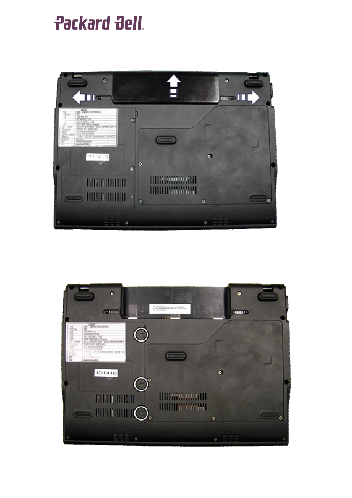
Battery
1. Push aside the 2 latches securing the battery.
Fig. 1 Removing the battery.
2. Pull out the battery.
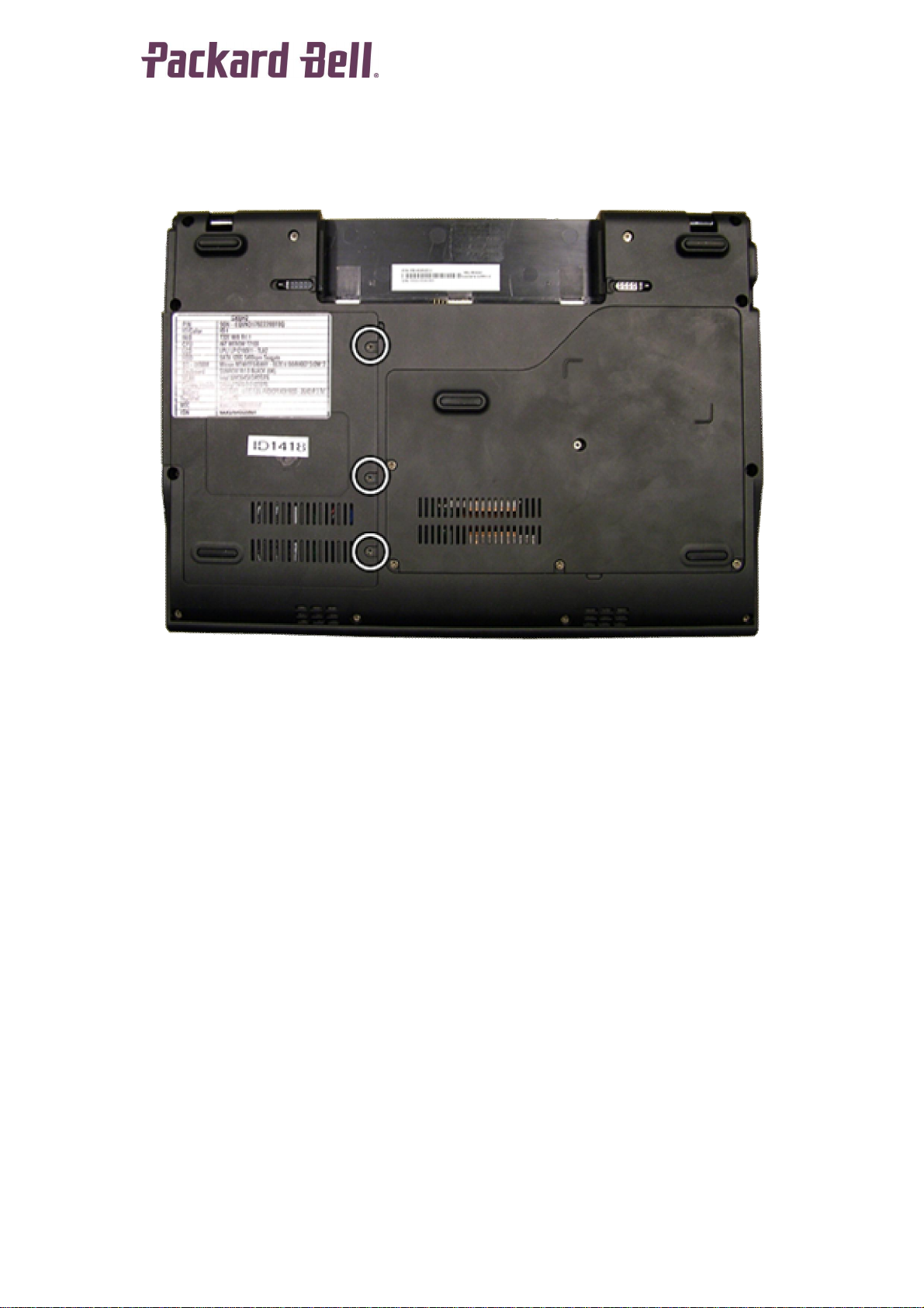
Hard Disk
1. Remove the battery as described above.
2. Remove the 3 screws securing the hard disk cover.
Fig. 2 The HDD cover.
EasyNote BG Disass embly Manual
4
Page 5
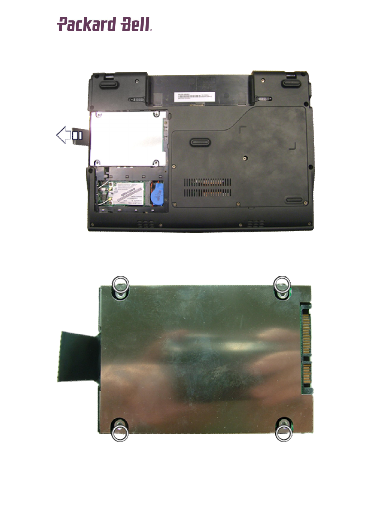
3. Remove the HDD cover.
4. Pull the plastic tab on the drive to disconnect it.
Fig. 3 The HDD cover.
5. Take the drive out if its compartment.
6. Remove the 4 screws of the HDD bracket.
Fig. 4 The HDD flat cable.
7. Take away the bracket from the hard drive.
EasyNote BG Disass embly Manual
5
Page 6
Wireless LAN
1. Remove the battery as described above.
2. Remove the 3 screws securing the hard disk cover.
Fig. 5 The HDD cover.
3. Remove the HDD cover.
4. Disconnect the 2 antenna cables from the Wireless LAN card.
5. Remove the 2 screws holding the card.
EasyNote BG Disass embly Manual
6
Page 7

Fig. 6 The wireless LAN screws and cables.
6. The left end of the card will now jump up.
Fig. 7 The wireless LAN card.
7. Carefully take out the Wireless LAN card.
EasyNote BG Disass embly Manual
7
Page 8

Memory
1. Remove the battery as described above.
2. Remove the 5 screw securing the CPU cover.
Fig. 8 The CPU cover.
3. Remove the CPU cover.
4. Release the metal clips that secure the memory modules and take
out the module(s).
Fig. 9 The bottom of the notebook.
EasyNote BG Disass embly Manual
8
Page 9

Keyboard
1. Remove the battery as described above.
2. There are 5 small slots; insert a small flat-b lade screwdriver in each
slot to unlatch the keyboard.
Fig. 10 The keyboard clips.
3. Carefully unlock the white clamp.
4. Slide the keyboard cable out of the connector.
Fig. 11 The keyboard flatcable.
EasyNote BG Disass embly Manual
9
Page 10

CPU Fan
1. Remove the battery and CPU cover as described above.
Fig. 12 The CPU fan.
2. Remove the single screw holding the CPU fan.
3. Disconnect the fan’s power cable.
4. Take the fan out of the notebook.
Heatsink
1. Remove the battery and CPU fan as described above.
2. Remove the 6 screws holding the heatsink.
3. Carefully lift the copper arm a little. Be careful with the thermal
paste between the heatsink and the mainboard.
4. Slide the heatsink to the left out of the casing.
EasyNote BG Disass embly Manual
10
Page 11

Fig. 13 The heatsink.
CPU
1. Remove the battery, fan and heatsink as described above.
2. Use a small flatbed scr ewdriver to unlock the CPU.
Fig. 14 The CPU.
Top Cover and Touchpad
1. Remove the battery and keyboard as described above.
2. Remove the single screw of the CPU fan, but do not remove the
CPU fan itself.
3. Remove the 12 screws holding the top cover.
EasyNote BG Disass embly Manual
11
Page 12

Fig. 15 The top cover screws.
4. Turn over the unit and remove the 3 screws securing the top cover.
5. Disconnect the 2 cables.
6. Unclip the latches around the edge of the top cover.
Fig. 16 The top cover screws.
LCD Assembly
1. Remove the battery, hard disk, keyboard, CPU fan and top cover as
described above.
EasyNote BG Disass embly Manual
12
Page 13

2. Disconnect the 6 cables connecting the LCD panel to the
mainboard.
3. Disconnect the cables from the WLAN card. Make sure the tape
securing them is removed everywhere.
4. Remove the 6 hinge screws.
Fig. 17 The hinge screws and LCD cable.
5. Remove the 5 rubber p lugs an d the 5 screws underneath them.
EasyNote BG Disass embly Manual
13
Page 14

Fig. 18 The LCD cover screws.
6. Lift of the bezel. The LCD panel and webcam will be revealed.
7. Remove the 4 screws.
Fig. 19 The LCD panel screws.
8. Take out the LCD panel.
EasyNote BG Disass embly Manual
14
Page 15

VGA Board
1. Remove the battery, keyboard, CPU fan and top cover as described
above.
2. Disconnect the VGA board connector cable from the mainboard.
3. Remove the 2 screws.
Fig. 20 The connectors and screw for VGA board.
4. Remove the VGA board.
Fig. 21 The VGA board.
EasyNote BG Disass embly Manual
15
Page 16

Power/Ethernet Board
1. Remove the battery, keyboard, CPU fan and top cover as described
above.
2. Disconnect the cable connector.
3. Remove the 2 screws holding the board.
Fig. 22 The power/Ethernet board.
4. Remove the board.
Mainboard
5. Remove the battery, keyboard, CPU fan and top cover as described
above.
6. Disconnect the 7 cables from the mainboard.
7. Remove the 3 screws.
EasyNote BG Disass embly Manual
16
Page 17

Fig. 23 The mainboard screws and connectors.
8. Remove the mainboard.
EasyNote BG Disass embly Manual
17
Page 18

Reassembly Notes
When reassembling the dev ice, please take notice of the order in which the
parts can be put back and reattached.
Notice
The information in this gu ide is subject to change without notice.
This guide contains information protected by copyright. No part of this guide
may be photocopied or reproduced in any form or by any means without prior
written consent from Packard Bell B.V.
PACKARD BELL B.V. SHALL NOT BE LIABLE FOR TECHNICAL OR
EDITORIAL ERRORS OR OMISSIONS CONTAINED HEREIN; NOR FOR
INCIDENTAL OR CONSEQUENTIAL DAMAGES RESULTING FROM THE
FURNISHING, PERFORMANCE, OR USE OF THIS MATERIAL.
Copyright © 2008 Packard Bell B.V. All rights reserved.
First Edition: April 2008
Version: 1.0
Packard Bell B.V.
EasyNote BG Disass embly Manual
18
 Loading...