

Page 1

XPRESS
E
■■■■■■■
■■■■■■■
■■■■■■■
■■■■■■■
■■■■■■■
■■■■■■■
5800 ST8000
Disk Expansion Unit
User's Guide
■■■■■■■
■■■■■■■
■■■■■■■
■■■■■■■
■■■■■■■
■■■■■■■
■■■■■■■
■■■■■■■
PRINTER NOTE: Page size 9” x 9.25”. Align t his page to top, right ha nd corner. Back box bleeds off
top and righ t edge. Left side of page extends to 9.25 inches.
Page 2

XPRESS
E
■ ■■■■■■
■ ■■■■■■
■ ■■■■■■
■ ■■■■■■
■ ■■■■■■
■ ■■■■■■
5800 ST8000
`)
Disk Expansion Unit
User’s Guide
■ ■■■■■■
■ ■■■■■■
■ ■■■■■■
■ ■■■■■■
■ ■■■■■■
■ ■■■■■■
■ ■■■■■■
■ ■■■■■■
PRINTER NOTE: Page size 9” x 9.25”. Align t his page to top, right ha nd corner. Back box bleeds off
top and righ t edge. Left side of page extends to 9.25 inches.
Page 3

Copyright © 1998 Packard Bell NEC, Inc.
Trademarks
n
Stor and the nStor logo are trademarks or r egister ed t r adem ar ks of nStor Corporation, Inc.
TolerANT is a registered trademark of Symbios Logic.
Microsoft® Windows®, and Microsoft ® W indows NT™ are registered trademarks or tradem ar ks of
Microsoft Corporat ion in the United Stat es and/ or in other countries.
NetWare and Novell are registered trademar ks of Novell,Inc.
SCO UNIX is a registered tademark of Santa Cruz O per at ions, Inc.
MS-DOS is a registered trademar k of M icr osof t Corpor ation.
Mylex is a registered trademark of M y lex Corporat ion
Other product and company names are registered trademar ks and t r adem arks of their respective holders.
Printed in the United States of America.
PN: 102157 3/98
PRINTER NOTE: Page size 9” x 9.25”. Align t his page to top, right ha nd corner. Back box bleeds off
top and righ t edge. Left side of page extends to 9.25 inches.
Page 4

Contents
1 Introduction
Welcome.........................................................................1
Features..........................................................................1
Where to Find Answers .....................................................3
Front Panel Component s ...................................................4
Operator Contr ol Panel ....................................................4
Power-On LED ................................................................5
Status Indicator LEDs ......................................................6
Alarm Speaker ................................................................7
Door Lock.......................................................................7
Status LEDs ...................................................................7
Activity LEDs..................................................................8
Rear Panel Components ....................................................9
I/O Interface Card .........................................................10
Power Cord Connector and F use ..................................... 10
Internal Components ....................................................... 11
Hot Swappable Disk Drives ............................................. 12
Power Switch ................................................................ 12
Fault LEDs ................................................................... 13
SAF-TE Card ................................................................13
Hot Swappable Cooling Fans .......................................... 13
Hot Swappable Power Supplies ....................................... 14
Configuration Modules ................................................... 15
SAF-TE ........................................................................16
................................................................
1
2 Installation
Setup ............................................................................ 17
Guidelines.................................................................... 18
Rack-Mount Subsystem Assembly................................... 19
Component Installat ion .................................................. 21
Cabling Configuration ..................................................... 25
Termination .................................................................. 26
Cables ......................................................................... 27
Ultra Wide SCSI Mode................................................... 28
Other Configurations....................................................... 32
3 Using the DEU
PRINTER NOTE: Page size 9” x 9.25”. Align t his page to top, right ha nd corner. Back box bleeds off
top and righ t edge. Left side of page extends to 9.25 inches.
................................................................
...........................................................
17
33
Page 5

Power-On Self Diagnos tics.............................................. 33
RAM Read/Write, RO M Checksum, and Register
Read/Write F ailures ...................................................... 34
RAM Checksum Failure .................................................. 34
SCSI Bus Access Failure ............................................... 35
LED Descriptions............................................................36
Operator Contr ol Panel ................................................... 37
Startup Scr eens ............................................................ 38
System Status Icon ....................................................... 39
Main Menu.................................................................... 40
Hardware Menu ............................................................. 41
Options Menu ............................................................... 45
Heat Threshold ............................................................. 48
SAFTE CHAIN ID .......................................................... 49
Change Passcode.......................................................... 50
Unlock Options.............................................................. 51
4 Maintenance
Replacing a Disk Drive.................................................... 53
Replacing a Power Supply............................................... 54
Replacing the Cooling Fans ............................................. 56
Replacing the DEU Cabinet ............................................. 58
Replacing a Fuse ........................................................... 59
5 Troubleshooting
A Certificate and Agency Information
FCC Radio Frequency I nterference St atement................... 65
Power Cord Selection ..................................................... 67
B Glossary
..............................................................
.......................................................
......................
..................................................................... 69
53
61
65
PRINTER NOTE: Page size 9” x 9.25”. Align t his page to top, right ha nd corner. Back box bleeds off
top and righ t edge. Left side of page extends to 9.25 inches.
Page 6

C Technical Information
Specifications ................................................................ 73
Connectors and Jumper s ................................................. 75
Connectors................................................................... 75
Jumpers....................................................................... 77
.............................................
73
D Option Cards
Introduction ................................................................... 85
Features........................................................................ 86
Quick Install .................................................................. 87
DEU Subsystems Installations......................................... 88
Setup ........................................................................... 88
Single-Ended Ultra W ide SCSI ........................................ 93
Differential Ultra Wide SCSI......................................... 105
Default Configurations .................................................117
Option Card Specifications ............................................ 118
.............................................................
85
PRINTER NOTE: Page size 9” x 9.25”. Align t his page to top, right ha nd corner. Back box bleeds off
top and righ t edge. Left side of page extends to 9.25 inches.
Page 7

xxxx
PRINTER NOTE: Page size 9” x 9.25”. Align t his page to top, right ha nd corner. Back box bleeds off
top and righ t edge. Left side of page extends to 9.25 inches.
Page 8

1 Introduction
Welcome
Congratu lations on the purchase of your new ST8000
Disk Expansion Unit (DEU). The DEU provides a
superior fault-tolerant n etwork stor age solution in a
subsystem-based SAF-TE compliant RAID enclosure.
The SAF-TE compliant interface provides a standard,
non-pr oprietary means for the RAID subsystem to
automatically in tegrate with peripheral p ackaging that
supports statu s signals, hot sw apping dr ives and
enclosure monitoring. Combined with the enterprisewide RAID manag ement softwar e, additional lev els of
fault toleran ce can be maintain ed.
The DEU is an eight drive enc losure designed to
support a h ost system-based ar chitectu re. Th e
architec ture suppo rts Ultra Wide SCSI (F ast-20).
Features
The following are major features of the DEU disk array
subsystem:
RAID Levels — Sup ports RAID lev els 0, 1, 3, 5, 10
(1 + 0), 30, and 50.
Configuration — Deskside towe r-based syste m and
rack-mou nt system (fits in to a standard IAE 19- inch
rack assembly). Dual-Bus or Single-Bus
configu ration module s provide for an “easy” PCB
plug-in c hangeable bu s configu ration.
Drive Support — Up to eig ht 3.5-inch , half-he ight
form facto r, hot swap pable drives th at use SCA-II
technology. Disk drives featured include high
performan ce 7,200 and 10, 000 RPM Ultra SCSI har d
disks.
Scalable Capacities — Drive capacities are
expandable and even further expansion through
daisy-chaining of multiple cabinets.
PRINTER NOTE: Page size 9” x 9.25”. Align t his page to top, right ha nd corner. Back box bleeds off
top and righ t edge. Left side of page extends to 9.25 inches.
Page 9

Hot Swap Power Supplies — Dual h ot swappable
power supplies expandable to three, all with current
sharing circu itry. Power supply system provides
monitorin g and sequen cing.
Cooling — Dual high capacity cooling fans.
Notifi cation s — LEDs and audible alarms prov ide
failure no tifications.
Inside door panel Fault LEDs provide drive failur e
identification .
Front Panel — A password protected Operator
Control Panel (OCP) for administration control and
monitoring functions, including control of SCSI ID
settings. An imated OCP icon s for an “at-a-g lance”
determination of system status.
Option Cards — Full support for Option cards
available in Differ ential Converter an d Ultra
Extender versions pr oviding data transfer r ates up
to 40 MBs per second. Both support either single or
dual bus Dif ferential SCSI and Ultra SCSI
applications.
Termination — Option cards configured for
automatic SCSI-bu s termination.
Remote/Delay Start — A backplane ju mper
provides for subsystem control of disk drive spin u p
delay whe n the adapter does not suppl y this
feature.
SCSI-to-SCSI Support — Support for an Ultra S2S
RAID Controller prov iding on-board Ultra SCSI-toUltra SCSI RAID processing.
Locking Door — A key-locking fr ont door th at
deters unauthorized access to the drives,
controllers, and power switch.
SAF-TE — Complete support of SAF-TE v1.0
standards (SCSI Accessed Fault Tolerant Enclosure)
protocol.
Cluster-Ready — Cluster-ready su bsystem (refer
to the Ultra S2S User’s Guide).
OS Support — Supports the following OS
platforms: Nov ell NetWare, M icrosoft® Win dows
NT™, and SCO UNI X compatible.
PRINTER NOTE: Page size 9” x 9.25”. Align t his page to top, right ha nd corner. Back box bleeds off
top and righ t edge. Left side of page extends to 9.25 inches.
Page 10

Storage Management Solution — Enterprise-
wide manag ing and mon itoring sof tware.
Where to Find Answers
When you have questions about your DEU there are
several places you can look to find answers. Refer to
the following:
In this guide: This user’s guide provides detailed
information f or installing an d using the DEU disk
array subsy stem. The man ual assumes that the
reader is already familiar with the operatin g system
environments w here the DEU will be in stalled.
ServerCare™ Service Support Progra m Guide:
Use this manual to loc ate telephone numbers for
customer service, technical support, and conditions
of the limited warranty.
Ultra S2S RAID Controller User’s Guide:
Use this manual for pr ocedures to install and u se
the Ultra S2S RAID Co ntroller ( DAC960SX), the
S2S Interface card, an d the software utility for each
specific operating system.
PRINTER NOTE: Page size 9” x 9.25”. Align t his page to top, right ha nd corner. Back box bleeds off
top and righ t edge. Left side of page extends to 9.25 inches.
Page 11
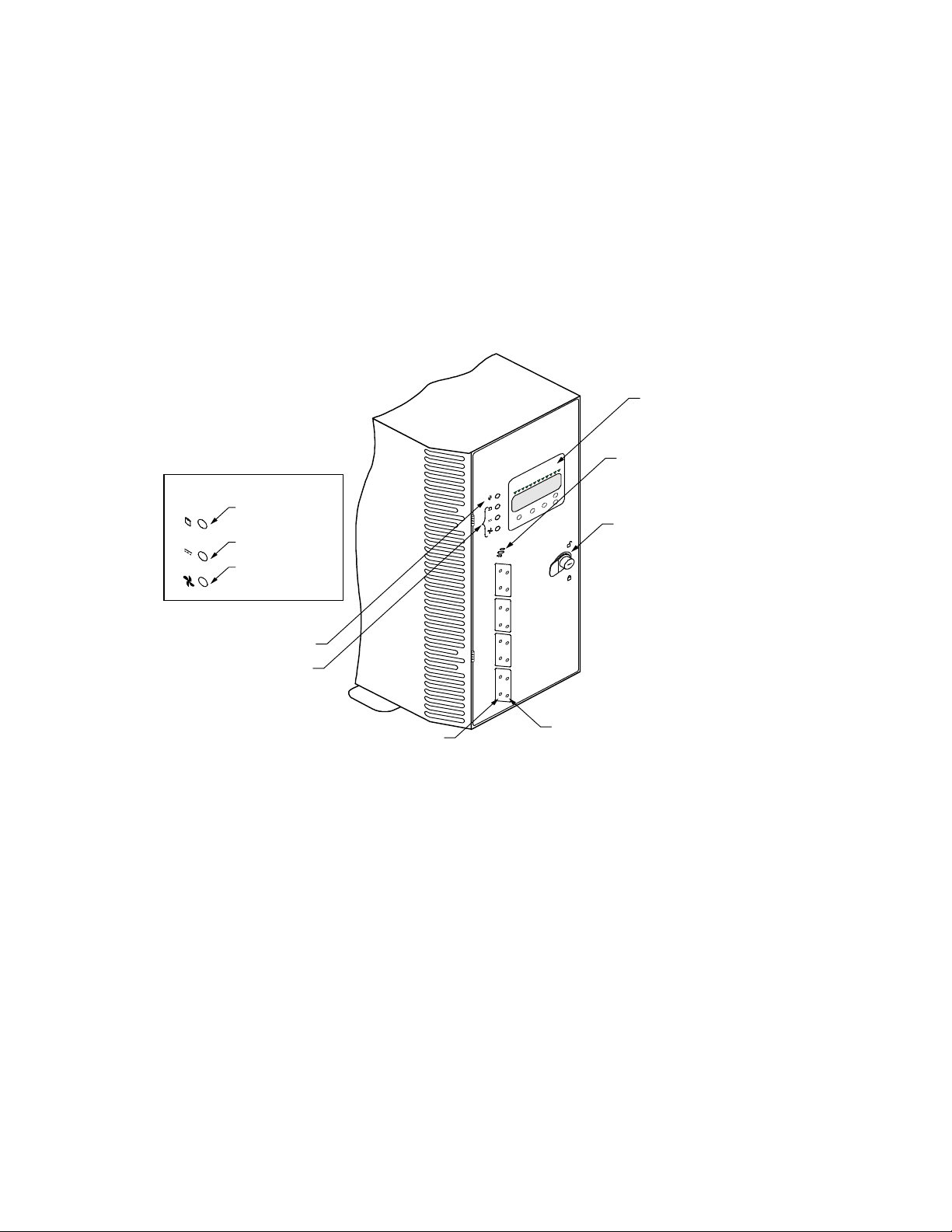
Front Panel Com ponents
The DEU front panel comprises seven major
components: Operator Control Panel, Power -On
Indicator LED, Status In dicator LED s, Alarm Speaker ,
Door Loc k, Status LED s, and Activi ty LEDs.
Status Indicator LEDs
Channel Mode LED
Power Supply LED
Fan Status LED
Operator Control
Panel (OCP)
Speaker
Door Lock
Power-On LED
Status Indicator LEDs
Status LEDs
Operator Control Panel
The Operator Control Panel (OCP) provides for the
control and mon itoring capabilities of th e DEU disk
drives, power supplies, fans, and processor. From the
panel’s interface, the user can change SCSI IDs for the
drives and SAF-TE processor, monitor the cabinet
temperatur e and chan ge the temper ature thr eshold for
the monitor ing syste m.
Other menu functions prov ide for viewing component
system status, sile ncing th e audible alarm, establishing
a password protection, determining which feature cards
have been installed, establishin g intra-cabin et
communic ations (master/ slave) and r eading fir mware
information.
Note:
Activity LEDs
LEDs normally visible
only when illuminated,
shown here for identification.
PRINTER NOTE: Page size 9” x 9.25”. Align t his page to top, right ha nd corner. Back box bleeds off
top and righ t edge. Left side of page extends to 9.25 inches.
Page 12

The OCP provides a four line by twenty character
display. There are five func tion keys for a menu driven
interface .
An animated icon will appear on a static display and
provides an “at-a-glanc e” look at system statu s. When a
“happy” animate d face appear s, all systems are
indicating a nominal state. Whe n the animated fac e
chang es to a “sad” face, th e system indic ates that a
problem has bee n detected an d requests y our attention .
The “power system” status will display the total power
available per dr ive slot in red undant and n onredund ant mode. A maximu m supported value of 30
watts per driv e bay is available in either mode. The
user can also view ind ividual pow er supply statu s and
configurations.
Cabinet temperatu re is measured w ithin the dr ive bay
area between drive slots 2 an d 3, and slots 7 and 8. By
sensing c abinet temperatur e in these loc ations, the
system provides the most sensitive measurement for
maximum protec tion. The temperature is d isplayed in
both Celsius and Fahrenheit. A SAF-TE processor
monitors the performan ce of each of the fan s via tach
pulses which tracks the speed of each fan impeller. The
OCP displays in formation abou t the speed of e ach fan.
Fan speed is co ntrolled via th e internal c abinet
temperatur e, refer enced fr om the user -established
temperatur e threshol d.
Power-On LED
The Power-On LED signifies that the DEU system has
power applied.
Status Indicator LEDs
There ar e three Statu s Indicator L EDs to assist the
user in dete rmining th e curren t state of the DEU
subsystem. Th e followin g subsection s describe eac h
LED.
PRINTER NOTE: Page size 9” x 9.25”. Align t his page to top, right ha nd corner. Back box bleeds off
top and righ t edge. Left side of page extends to 9.25 inches.
Page 13

Channel Mode
Power Supply Status
The Chann el Mode LED indicates the status of the
array su bsystem by ch anges in its co lor and state.
When illuminated steady g reen, the LED in dicates
normal arr ay activities.
When the L ED chang es to amber (flash ing or ste ady) it
indicates abno rmal activities, f or more info rmation see
LED Descriptions described late r in this gu ide.
The Powe r Supply Statu s LED indicate s the conditio n
of the power supplies by change s in its color. The LED
will illuminate steady gr een when all the pow er
supplies are func tioning nor mally and will chan ge to
amber if one o f the power supplies should f ail. The LED
will also switch to amber if the pow er system is in a
non-re dundant state. A failed compon ent can be
identified v ia the Operator Control Pane l and the lack
of a “DC Good” LED located on each power supply unit.
Fan Status
Alarm Speaker
The Fan Statu s LED indicate s the conditio n of the
cooling fans by changes in its c olor. The LED w ill
illuminate green w hen all of the fans are f unctioning
normally an d will chang e to amber if any of the fans
should fail.
When a failed component is present, use the Operator
Control Panel to identify the failed fan, see Hardware
Menu described later in this guid e. The fans ar e
identified on the rear doo r panel via plac arded
marking s.
An audible alarm will soun d when any component’s
condition change s to an abnormal state. The Status
Indicator LEDs will pr ovide a general area of failure by
the LED co ndition (colo r and/or state ), and the faile d
componen t can then be identified using the Oper ator
Control Panel.
To silence th e alarm, acce ss the contr ol panel and
select “Tur n Off Alarm”, see Main Menu described late r
in this guide.
PRINTER NOTE: Page size 9” x 9.25”. Align t his page to top, right ha nd corner. Back box bleeds off
top and righ t edge. Left side of page extends to 9.25 inches.
Page 14

Door Lock
Status LEDs
The fron t door has an integral loc k that also serv es as
a door handle. In addition, the door lock provides
security to deter un authorize d access to the internal
components. Two keys are provided with the system.
To unlock the door, insert the key and tu rn it in a
counterclockwise direc tion. To lock the door, turn the
key in a clockwise direction.
There ar e eight Status L EDs located in th e window s on
the front panel (for the rack-mount system they are the
lower set of LEDs and for the tower -based system will
be the set on th e left hand sid e).
These LEDs, in conjunction with an approved RAID
controlle r, will indicate the status of that spe cific disk
drive. The con dition of the drive is indicated by the
LED’s state (f lashing or steady) and/ or color (amber or
green).
Activity LEDs
For more in formation on interpretin g these indic ations,
see LED Descriptions described later in this guide.
There are eight Activity LEDs located in the windows
on the front panel (for the rack-mount system they are
the upper set of LEDs an d for the tower-based system
they will be the set on th e right hand side). These
LEDs display a spe cific driv e’s activity , such as reads
or writes.
PRINTER NOTE: Page size 9” x 9.25”. Align t his page to top, right ha nd corner. Back box bleeds off
top and righ t edge. Left side of page extends to 9.25 inches.
Page 15
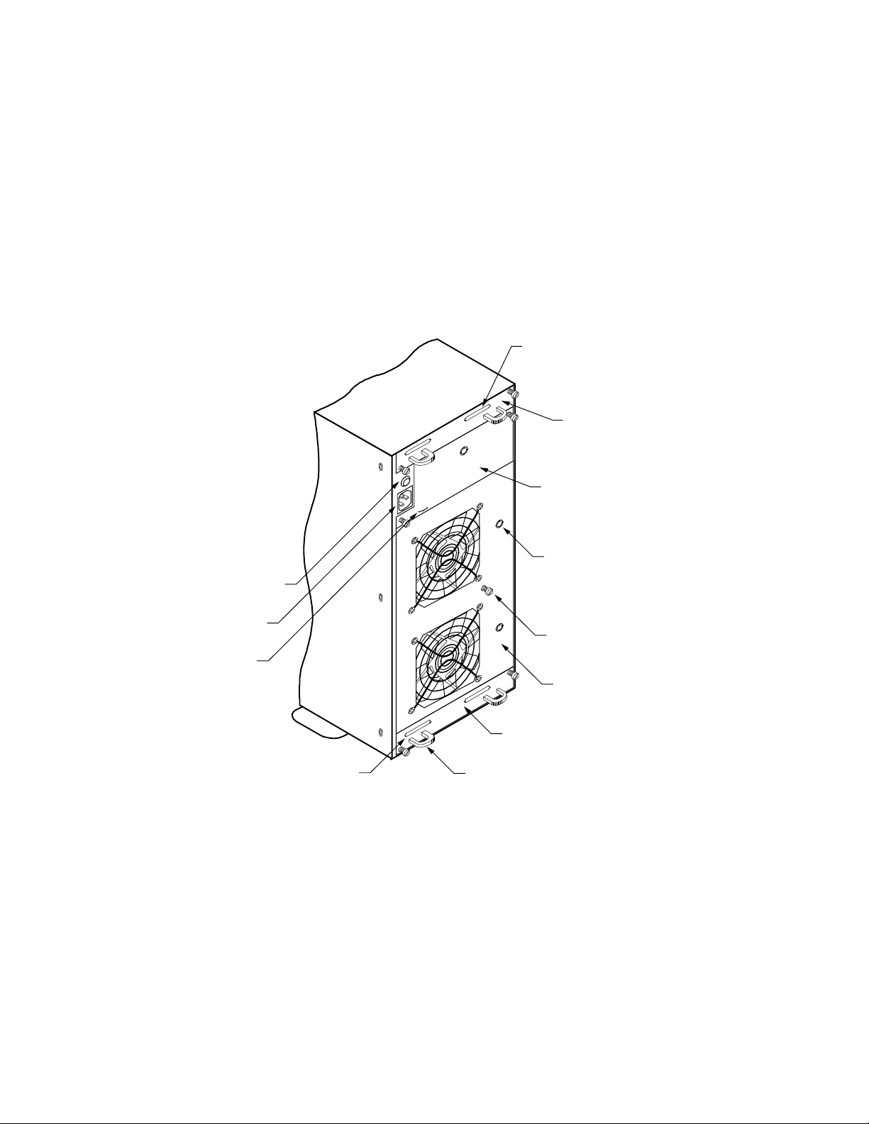
Rear Panel Com ponents
The DEU re ar panel co mprises four major compon ents:
I/O Interface cards, power cord connector module, fuse,
and access d oors to powe r supplies and f ans.
VHD SCSI
Connector
I/O Interface Card
Power Supply #3
with PSU Cover Plate
PSU “DC Good” LED
Fuse
AC Power Cord
Connector
AC Power Cord
Retainer
VHD SCSI
Connector
I/O Interface Card
Rear Door Fastener
Rear Door Panel
I/O Interface Card
Card Handle
The I/O Interface card makes up the connection from
the subsystem’ s bus to the RAID controlle r. Located on
the I/O I nterface c ard are two 68-pin ver y high density
(VHD) SCSI connectors. They provide the in terface
connec tion from th e subsystem bus to the RAID
controller or host adapter. The connectors are labeled
Channel 0 an d Channel 1.
PRINTER NOTE: Page size 9” x 9.25”. Align t his page to top, right ha nd corner. Back box bleeds off
top and righ t edge. Left side of page extends to 9.25 inches.
Page 16

The I/O Interface card inco rporates bu ilt-in automatic
SCSI termination. When the data c able is plugge d in,
the system au tomatically senses th e conne ction and
provides the required SCSI termination.
Two sets of jumpers are provided on the card. One set
routes Term Power in the event that the host controller
is not providing it.
The nex t set of jumper s addresses a spe cific set of
controllers that use the DEC Fault Bus protocol. If you
are using a DEC system where the controller uses this
protocol, you w ill need to jumper locations (jumper on
both pins) JP3 an d JP4 for eac h chann el that has an
external SCSI cable con nected. This will disable
termination at th at point.
If you ar e using a stan dard host adapter that prov ides
Term Power, no ch ange is required and SCSI bus
termination w ill occur au tomatically.
Power Cord Connector and Fuse
The power cord connector supplies the AC power to the
DEU through a power cord connected to a conventional
three-h ole groun ded outlet or p ower strip. A 250V 10
amp fuse is provided to protect the system from any
electrical f ault.
Internal Components
There ar e seven pr imary inter nal compon ents: disk
drives (up to eight), Fault LEDs, power switch, SAF-TE
card, h ot swappable coo ling fans, h ot swappable pow er
supplies, and configuration module (Dual-Bus or
Single-Bus).
PRINTER NOTE: Page size 9” x 9.25”. Align t his page to top, right ha nd corner. Back box bleeds off
top and righ t edge. Left side of page extends to 9.25 inches.
Page 17
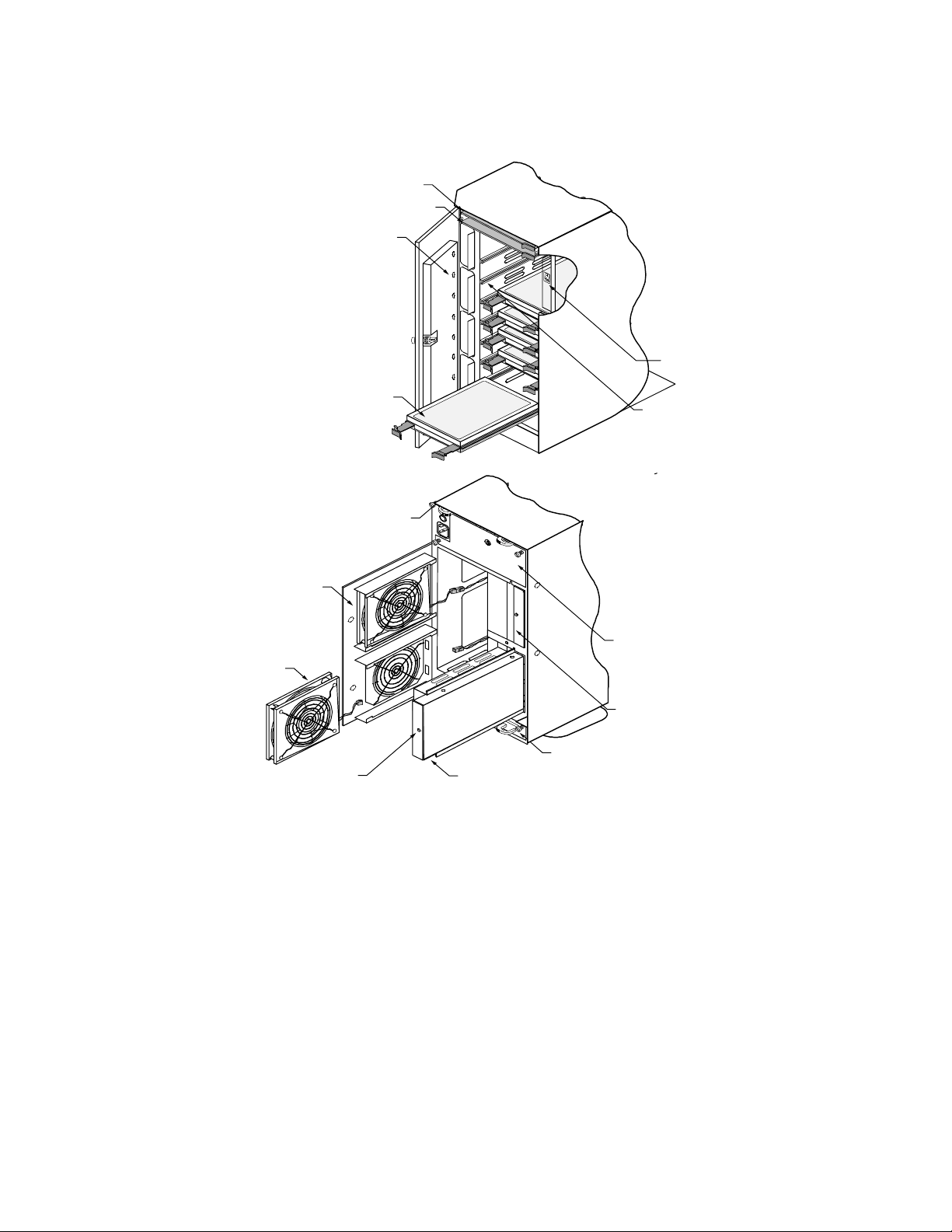
Optional Bay for
Ultra S2S RAID Controller
SAF-TE Card
Fault LEDs
Power On/Off
Switch
Hard Disk Drive
I/O Interface Card
Cooling Fan #2
Cooling Fan #1
“DC Good” LED
Hot Swappable Disk Drives
Power Supply #1
Drive Rails
Note: Cover shown cut-away
to illustrate recessed power switch.
Power Supply #3
with PSU Cover Plate
Power Supply #2
I/O Interface Card
The DEU uses high performance, 3.5-inch form factor
hot swappable disk drives. The drives are designed to
operate on Small Computer System Interface (SCSI)
and are SCSI-3/ SCSI-2 command c ompatible.
Each drive has an 80-pin Wide Single Connector
Attachment (SCA-I I) interface , designed to allow the
drive to be h ot plugge d directly in to the backplan e.
PRINTER NOTE: Page size 9” x 9.25”. Align t his page to top, right ha nd corner. Back box bleeds off
top and righ t edge. Left side of page extends to 9.25 inches.
Page 18

Power Switch
The drive mounting design incorporates a rail system
with built-in connec tors making it po ssible to “hot
swap” a drive without sh utting dow n the system. This
design allow s for easy installation with minimal for ce
and latchin g clips to secu re the driv es into place.
Note: All drives in an array shou ld be of the same
capacity. If the drives are mixed, all of the dr ives in
the array are assigned the capacity of the smallest size
drive.
The power switch is located inside the lockin g front
door and controls AC power to all of the power supplies.
This positioning of the switch deters unauthorized
users from powering down the D EU provided the door
is locked. The switch is recessed to prev ent inadvertent
activation du ring ser vice activ ity.
The switch is labeled with a “I” for the ON condition
and “O” for the O FF condition and is illu minated when
the power is on for easy identification. Depending on
the orien tation of the su bsystem (i.e. , in the r ack
configu ration) the “I” label will appear as a — and
should be inte rpreted as the ON condition .
Fault LEDs
SAF-TE Card
Drive Fault LEDs are provided inside the front door to
aide in identifying the failed (or problem) disk driv e.
These LEDs are aligned with their respective
drive/dr ive bay. An illu minated LED (amber) in dicates
the failed or problem drive.
The SAF-TE card contains the control and monitoring
electron ics for the subsystem cabin et. It prov ides the
central data lin k between th e enclosur e and the host
system.
PRINTER NOTE: Page size 9” x 9.25”. Align t his page to top, right ha nd corner. Back box bleeds off
top and righ t edge. Left side of page extends to 9.25 inches.
Page 19

Located in th e tower-base d systems’ top bay or the
rack-mount systems’ far left bay are two card slots. The
Ultra S2S RAID Controller (optional) an d the SAF-TE
card are installed in these two slots. The Ultra S2S
RAID Controller w ill be installed in the upper most (o r
furthest left) slot. Th e SAF-TE card is installed in the
next slot down or to the right.
Hot Swappable Cooling Fans
The cooling system consists of two high-performance
fans fitted to the rear panel. These fans draw air from
a high pressure plenum, across the drives and
electronics of the system and exhaust out through the
rear door panel.
The fan speed is thermally controlled to provide
reduced operating noise levels. In the event of a fan
failure or cabinet temperatu res approac hing the
threshold limit, th e remaining f an will switch to
maximum operating speed.
Cabinet temperatu re is measured w ithin the dr ive bay
area between drive slots 2 an d 3, and slots 7 and 8. The
fan’s speed and alarms are k eyed to the h igher o f the
two temperatures. The SAF-TE processor monitors the
Access the O perator Con trol Panel to dete rmine the
cause and f ailed compone nt. Select “Har dware Me nu”
from the M ain Menu and choose “Component Status”,
see Operator Control Panel described later in th is
guide. The fans are identified on the rear door panel
using a plac ard for “FAN 1” and “FAN 2.” For more
information on chang ing a coolin g fan, see Replacing
the Cooling Fans desc ribed later in this guide.
Hot Swappable Power Supplies
Up to three 150 w att hot swappable po wer supplie s are
incorpo rated as part of a f ault-toleran t design (N+1
power system). Each power supply has current share
circuitr y whic h balances the lo ad between installe d
power supplies. In the event of a power supply failure,
the load is tran sferred to th e remainin g power su pplies
without in terruption to the DEU nor mal operation.
PRINTER NOTE: Page size 9” x 9.25”. Align t his page to top, right ha nd corner. Back box bleeds off
top and righ t edge. Left side of page extends to 9.25 inches.
Page 20

If a failure o ccurs, the Power Supply Status L ED will
illuminate amber an d the audible alarm w ill sound. Th e
user can id entify the f ailed componen t by accessing the
OCP and vi ewing the “Hardware Status.” The PSU “D C
Good” LED will not be illumin ated on the failed power
supply, see Replacing a Powe r Supply describe d later
in this guide.
PRINTER NOTE: Page size 9” x 9.25”. Align t his page to top, right ha nd corner. Back box bleeds off
top and righ t edge. Left side of page extends to 9.25 inches.
Page 21
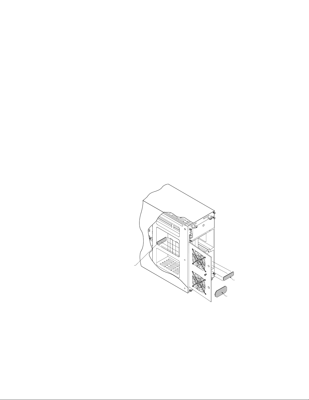
Configuration Modules
The DEU is available in two bus con figuration s which
is determined by the conf iguration mo dule installed.
The Dual-Bus modu le provides for a split bus desig n,
while the Single-Bus module connects both SCSI buses
together that can be used when all driv es are requir ed
on one SCSI bus.
The Single-Bus module is larg er in physical size th an
the Dual-Bus modu le and is easily identified by a
description silk-screened on the module card. It is
located on th e backplane pr inted circ uit board and is
accessed from the rear door panel.
The con figuration modules are installe d at location JP1
on the backplane PCB. The connector is keyed and th e
module will install only on e direction. For illu stration
purposes, the tower system is used to depict the
location of th e modules.
Backplane PCB
(JP1)
NOTE:
The cover is cut
away to demonstrate
the location of the installed
configuration module.
Dual-Bus Module
Single-Bus Module
PRINTER NOTE: Page size 9” x 9.25”. Align t his page to top, right ha nd corner. Back box bleeds off
top and righ t edge. Left side of page extends to 9.25 inches.
Page 22

SAF-TE
The DEU is designed to be compliant with SAF-TE
(SCSI Accessed Fault-Tolerant Enclosure) specification
version 1.0. Un der this specification, the enclosure is
implemented as an assignable SCSI targ et ID. Th is
allows standardized alert detection and status
reportin g using th e SCSI bus as the u nderlyin g
transport me chanism.
Disk drives, power supplies, cooling fans and
temperature are contin ually monitor ed and these
conditions are then reported over the SCSI bus to the
host system. When used in conjunction with RAID
managemen t software, th e DEU can aler t the user o r
LAN administrator of impending or imminent
conditions r equiring th eir attention. T hese alert
notification s can be made v ia network broadcast or
electronic pages, in addition to the LEDs and Oper ator
Control Panel alerts found on the DEU. This allows the
administrator to react to con ditions that cou ld normally
go unnoticed until data loss.
PRINTER NOTE: Page size 9” x 9.25”. Align t his page to top, right ha nd corner. Back box bleeds off
top and righ t edge. Left side of page extends to 9.25 inches.
Page 23

2 Installation
Setup
The installation o f your D EU disk array su bsystem is
essentially a th ree-step pr ocess: the su bsystem is setup
and its compon ents installed, th e cabling is co mpleted
based on the su pported c onfigur ations, and th e array is
then configured.
The DEU is designed with an open arch itecture that
allows for many possible combinatio ns of cabling
schemes. D ue to the in herent limitatio ns of sampling
all of the possible configu rations, we will pr ovide a few
of the most ty pical cabling schemes and impl ementation
of the con figuration modules.
Additional con figuration s are available thr ough the use
of Ultra Extender or Differential Converter Option
cards. Refe r to Appendix D for info rmation specific to
each card and configuration.
This chapte r is divided in to two section s: Setup and
Cabling Configuration. The Setup section provides the
instructio ns for assemblin g the rack -mount subsy stem,
and installing the h ardware componen ts (controllers,
disk drives, power supplies, etc.,) for both rack-mount
and deskside tower-based subsystems.
The Cabling Configuration section contains samples of
cabling sch emes and con figuration modules. If y our
desired configuration is not shown in the samples, refer
to the example mo st similar and follow the cabling
topology schemes exp anding the example to fit y our
needs.
When configuring the array, refer to the Ultra S2S
RAID Controller User’s Guide provided with your
controller.
If you are setting up a rack-mount subsystem continue
with “Rack- Mount Subsy stem Assembly” desc ribed later
in this guide, otherwise skip to “Component
Installation” also desc ribed later in th is guide.
PRINTER NOTE: Page size 9” x 9.25”. Align t his page to top, right ha nd corner. Back box bleeds off
top and righ t edge. Left side of page extends to 9.25 inches.
Page 24

Guidelines
Before installation, you will need to co nsider the
following:
When referenc ing a component on the rear panel it is
■
assumed the user is facing the rear panel and when
referen cing the front panel c omponents th e
assumption is that th e user is fac ing the fr ont panel.
Interior temperatur e of the rac k cabinet sho uld be
■
maintained at ambien t temperature s but must not
exceed 117°F (47°C) during normal operation.
Remove each piece from the shipping carton, leaving
■
the disk driv es in their an ti-static protectiv e
packaging until you are ready to install them. Save
the packin g materials in c ase you ne ed to ship the
DEU.
Secure all cable connectors using the thumb screws
■
(finger tight only).
PRINTER NOTE: Page size 9” x 9.25”. Align t his page to top, right ha nd corner. Back box bleeds off
top and righ t edge. Left side of page extends to 9.25 inches.
Page 25
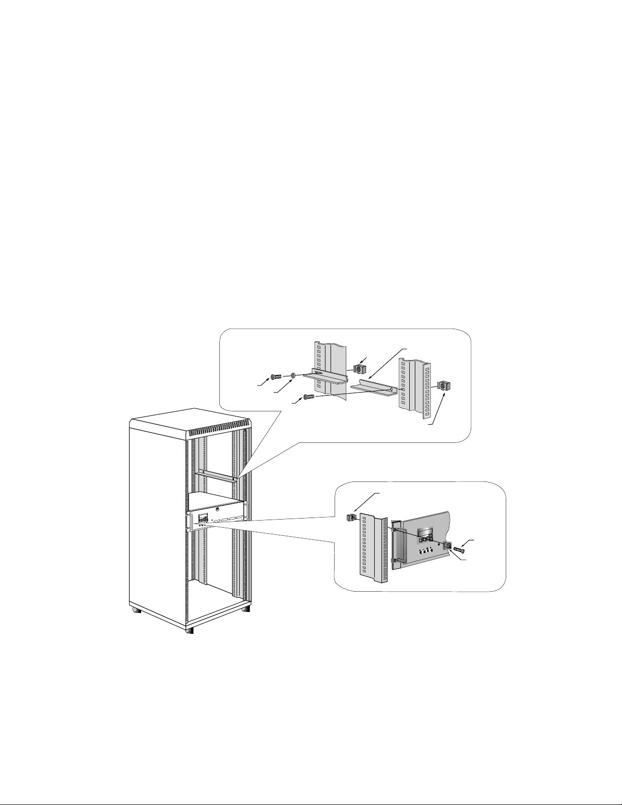
Rack-Mount Subsystem Assembly
Install the DEU in to any standar d IAE 19" rack
cabinet.
Caution: Ensure th at the location o f the DEU does no t
create an u nstable condition when in stalled in the rac k
cabinet enclosure.
Note: Mount th e subsystem into the rack e nclosure
before installing the disk drives. Th is will reduce th e
weight required to support during installation.
Select an appr opriate location in your r ack cabinet
1
for the DEU. If you are installin g multiple systems,
review th e cabling c onfigur ation section late r in this
chapter f or your cable scheme to determine th e
optimum location .
Screw
Washer
Screw
Caged Nut
Caged Nut
Caged Nut
Support Bracket
Front Bezel
Screw
Plastic
Washer
PRINTER NOTE: Page size 9” x 9.25”. Align t his page to top, right ha nd corner. Back box bleeds off
top and righ t edge. Left side of page extends to 9.25 inches.
Page 26
2 Locate the two suppo rt brackets. Mount th e two
brackets to th e rack c abinet vertic als using the four
screws, two washers, and caged nuts provided. The
bracket h as a slotted hole and a c ounter sunk hole.
Mount th e slotted hole on th e rear ve rtical. The
slotted hole re ceives a “pan h ead” screw w ith a
washer and the countersunk hole receives a “flat
head” scre w.
Note: The caged nuts are secured into the rack cabinet
vertical slots by inserting one side of the nut into the
slot and squeeze while pressing the opposite side until
it snaps into plac e.
3 Install the caged nuts that will sec ure the fron t
bezel in step (6) prior to inser ting the DEU into the
rack assembly.
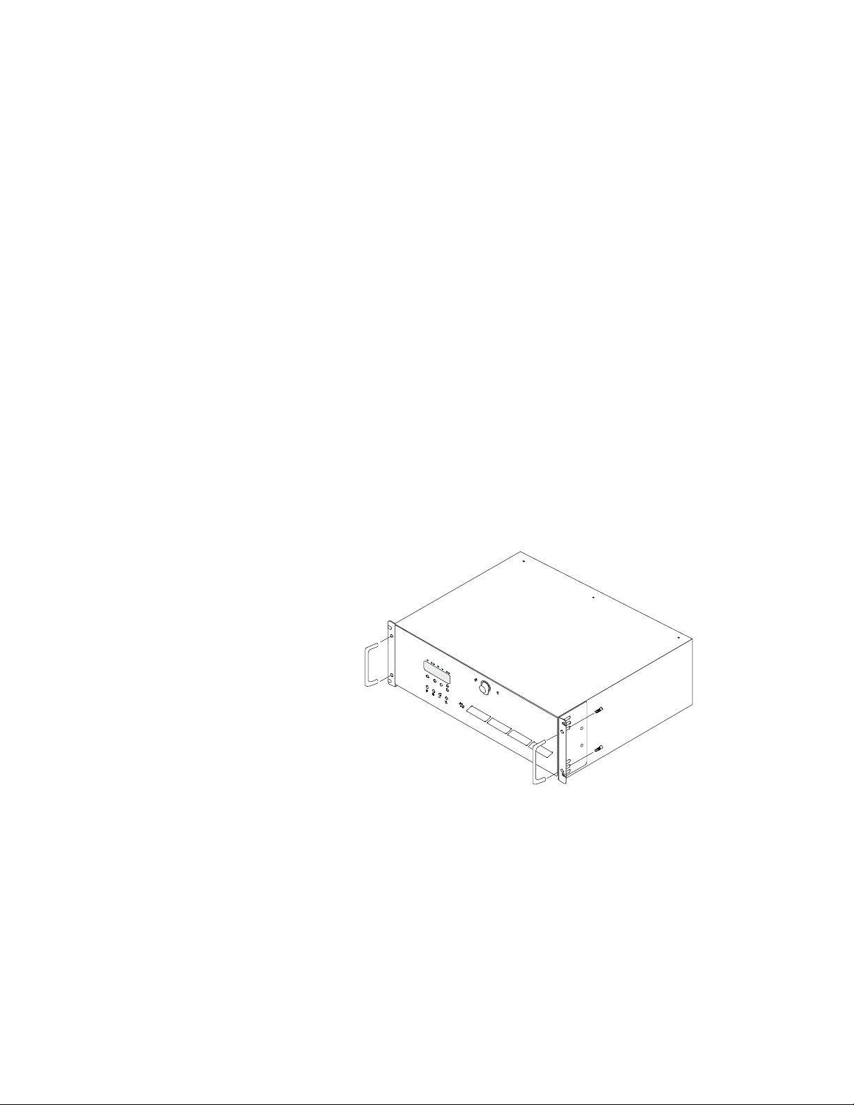
4 Locate the two “D” h andle assemblies.
a Position a handle assembly on each handle
mounting bracket loc ated on the side s of the
cabinet. The h andles are univer sal and will fit
either side.
b Secure the handles with the two screws provided.
5 Lif t the DEU up an d onto the su pport brack ets
previously installed in step 2. Slide the DEU toward
the rear o f the rack cabinet.
6 Sec ure the f ront bezel to the rack ver ticals using th e
four screws and plastic washers provided.
PRINTER NOTE: Page size 9” x 9.25”. Align t his page to top, right ha nd corner. Back box bleeds off
top and righ t edge. Left side of page extends to 9.25 inches.
Page 27

Component Installation
Caution: Disk drives and printed cir cuit board
componen ts are sensitive to electrostatic discharg e. To
preven t operating failu re or damag e, observe th e
following: Establish a ground for yourself by using the
wrist grounding strap, or by touching the metal chassis
prior to handling or installing the dr ives or printed
circu it board compon ents.
Down your server or power off your computer system
1
in preparation for installing the c ontroller.
Install the RAID Controller into your host computer.
2
For specific instructions, refer to your host system’s
manual.
The controller must be installed in slot 1 of the h ost
system (master slot) when booting from this
controller.
Caution: Exercise care when handling any hard disk
drive. Do not drop, jar, or bump the disk drives.
Remove on e of the disk dr ives from its an ti-static
3
protective packaging.
Holding the dr ive by its edges, loc ate the Drive
4
Latching Clips and pull out o n the latches to unlock
them.
The Drive Latching Clips are placed in the locked
position for shipping purposes.
Insert the d isk drive into the drive bay by aligning
5
its rails into the d rive bay slots, componen t side
toward the right on rack-mount systems or
component side down on tower-based systems.
Dual-Bus module: The drive slots are split into tw o
buses: one bus connects the left or upper front four
drive slots and the other bus connects the right or
lower front four drive slots. The Single-Bus module
connects all eight driv e slots to one bus.
Depending on which bus th e drives will be
configured to, begin populating the drives starting
with the far right slot or lowest slot for Channel 0
and the fifth drive slot for Channel 1.
PRINTER NOTE: Page size 9” x 9.25”. Align t his page to top, right ha nd corner. Back box bleeds off
top and righ t edge. Left side of page extends to 9.25 inches.
Page 28
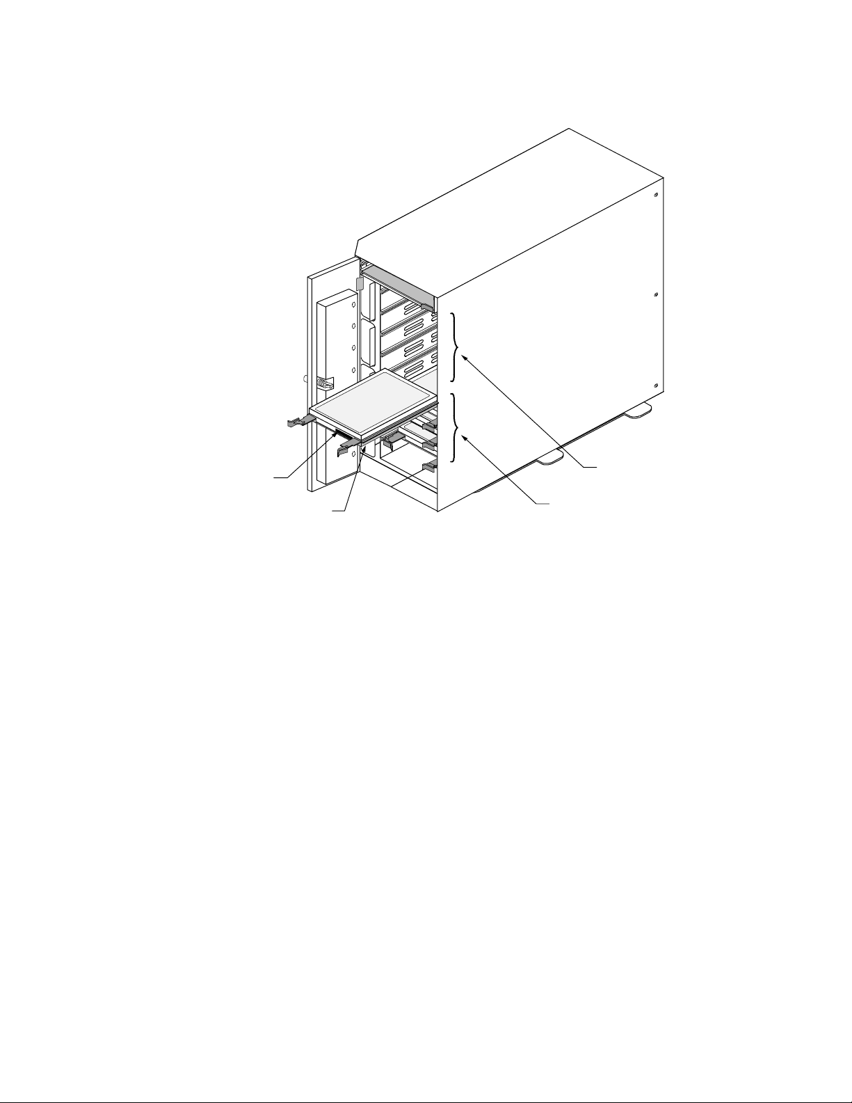
Populate drive bays from
the lower (right) slot first.
Drive Label
Component side
6 Fully seat the drive by applying light pressure with
Upper (left) bay,
four drive slots
Lower (right) bay,
four drive slots
Single-Bus module: Begin populating the drive with
the far right slot or lowest slot and work to your left
or up.
your th umb to the fr ont of the dr ive.
7 Press the Drive Latching Clips until they ‘snap ‘ into
place. The drive is now loc ked into position.
8 In stall the remainin g drives r epeating steps 3
through 7, until all the drives have been installed,
as desired.
Note: Verify that th e power switc h on the D EU is in
the OFF position (O).
9 Connec t one end of the power cord to the power
connector on the rear panel and the other end to a
three-hole grounded ou tlet or power strip. A UPS is
recommended.
10 Refer to th e Cabling Configuration section and
follow the procedures to cable your system.
PRINTER NOTE: Page size 9” x 9.25”. Align t his page to top, right ha nd corner. Back box bleeds off
top and righ t edge. Left side of page extends to 9.25 inches.
Page 29
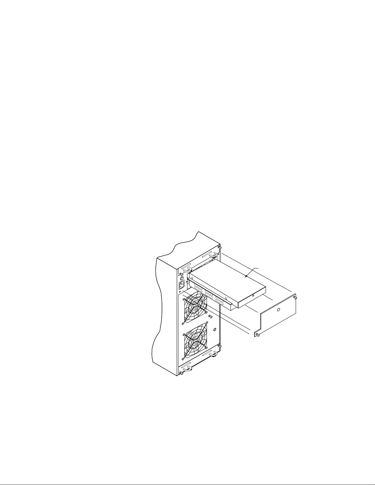
Installing the Third Power Supply
If you will be installin g five (5) or mor e disk drives you
will be required to in stall the third power su pply.
Note: There is no need to power off the D EU or the
computer system. The power supplies are hot
swappable.
1 Loosen the two screw s on the Power Supply #3 cover
plate using a f lat-blade screw driver and remove the
cover plate.
2 Remove th e power supply from its shipping package.
3 In stall the third power su pply by sliding th e PSU
into the cabin et until it reac hes its locked po sition.
Orient the supply as indicated in the illustr ation.
Note: Use care when inserting the power supply into
its fully seated position. Do not use a strong force to
seat the PSU into its matin g conn ector.
Power Supply #3
4 Remo ve the blank ing plug for the LED on the co ver
plate.
5 Re-install the cover plate. Secure the cover plate
with the tw o screws u sing a flat-blade sc rewdr iver
securing the power supply.
PRINTER NOTE: Page size 9” x 9.25”. Align t his page to top, right ha nd corner. Back box bleeds off
top and righ t edge. Left side of page extends to 9.25 inches.
Page 30

Cabling Configur ation
This section provides the recommended c able
configurations when operating the DEU in a specific
mode.
The Ultra Wide SCSI mode provides enhanced
perfor mances with data transfer s up to 40 MBs per
second (20 MHz).
Note: Be sure to enable the Ultra SCSI (Fast-20) mode
in the SCSI Adapter Setup.
The DEU sup ports the Amer ican National Stand ard
Ultra SCSI (Fast-20) par allel interfac e standards,
referred to as Ultra Wide SCSI. This standard is
backward compatible with F ast SCSI (SCSI-2 with th e
Wide option), also referr ed to as Fast Wide SCSI.
These standar ds define the me chanical, e lectrical, an d
timing requ irements. In compliance w ith these
interfac e standards, c ertain limitations app ly when
considering the configuration, lengths of cabling, and
termination. The conf iguration samp les and cables
provided with the subsy stem meet the r equirements o f
the specific ations. Mo difications to an y of these
variables can have less than desirable re sults when
operating any SCSI dev ice.
Termination
Termination is required at bo th ends of th e SCSI bus.
There are two sets of jumpers on the I/O Interface card.
One set of jumpers routes “Term Power” in the event
that the host controller is not providing it. The default
setting is the unjumpered condition (jumper offset on
one pin only). The secon d set of jumpers addresses a
specific set of controller s that use the D EC Fault Bus
protocol. If your controller uses this protocol, you will
need to jump er (jumper on both pins) at location JP3
and JP4 on th e backplane fo r the indic ated chann el
that will be used. A jumper at either of these location s
will disable termination at that poin t on the SCSI bus.
If you are using a controller that provides Term Power,
no chan ge is requir ed and SCSI bus ter mination will
occur automatically.
The Host Controller card provides termination for one
end of the SCSI bus, while the I/O In terface c ard
provides final termination at the other end of the bus.
PRINTER NOTE: Page size 9” x 9.25”. Align t his page to top, right ha nd corner. Back box bleeds off
top and righ t edge. Left side of page extends to 9.25 inches.
Page 31

JP3 and JP4
Fault Bus Protocol
Jumpers (Add to
disable termination)
Channel 0
Cables
Channel 1
I/O Interface Card
Channel 0 and 1
Term Power Jumpers
Cable length is another consideration when configuring
the subsyste ms.
When considering the total length of your cabling
requireme nts, the inter nal length of cables and prin ted
circuit bo ard traces (k nown as the in ternal cable
length) must be subtracte d from you r total cable
length. The DEU inter nal cable leng th is 36 inches.
For Ultra Wide SCSI , the total SCSI cable length is 3
meters (118 inch es) with fou r drives an d 1.5 meters (59
inches) w ith eight dr ives. After su btracting th e
internal len gth of 36 inc hes the remain ing cable len gth
is 82 inches or approximately 6.83 feet (2.08 meter s) for
four dr ives and 23 inch es or approx imately 1.9 feet (. 58
meters) for e ight driv es.
Because of the enhancements in the DEU, its possible
to extend be yond the limits set forth in th e
specification . Howeve r, a symptom fr om exceedin g this
cable limit is a SCSI bus loc kup or “fr eeze.” If y ou
experien ce a similar proble m and are aware of a
cabling limit issue, reducing th e length of cablin g and
return ing the total len gth to with in the specifie d limit
should resolve any problems.
If you h ave a cabling issu e and requir e more
information , contact Te chnical Su pport for fu rther
assistance. Data loss is possible under conditions of
SCSI bus lockup.
PRINTER NOTE: Page size 9” x 9.25”. Align t his page to top, right ha nd corner. Back box bleeds off
top and righ t edge. Left side of page extends to 9.25 inches.
Page 32

Note: Shielded data c ables, such as those prov ided
with the su bsystem, must be u sed to prev ent radio
frequency interference. It is recommended that you use
the cables provided with your system. These cables
have been tested and meet stringent guidelines set
forth by SCSI-3 ANSI specif ications.
Ultra Wide SCSI Mode
Several possible conf igurations exist f or the DEU in
Ultra Wide SCSI mode. However this manual will
discuss the tw o possible con figuration s using the I/O
Interface card in Ultra Wide SCSI mode: dual-bus
module in a single cabinet and single-bus module in a
single cabinet. Refer to the Appendix D when using the
Ultra Extender card.
Note: When co nfigurin g a dual-bus c abinet, both
channels of the Host Controller are connected to each
bank of drives through each channel on the I/O
Interface card. When configuring the single-bus
cabinet, one channel of the Host Controller connects
both banks of dr ives only th rough the right o r upper
channel (Channel 1) on the I/O Interface card.
Dual-Bus Cabinet
This configuration pr ovides two separate SCSI bus
connections to the drives.
From the front, the drives slots are divided into two
banks. The left or upper four front drive slots, which
are conn ected to “Chan nel 1” on th e I/O Inter face car d,
and the right or lower four front drive slots are
connected to “Channel 0” on the I/O Interface card.
The SCSI IDs of the drives are set by SAF-TE card
defaults to ID s 0, 1, 2, and 4, from the f ront begin ning
with the drive located on the right or lower slot of each
bank. Th e SCSI IDs can be man ually ch anged fro m the
OCP, if requir ed. Both banks of drives w ill use the
same sequence of SCSI ID numbers when the Dual-Bus
module is installed.
Note: SCSI ID 3 is reserved for the SAF-TE card
processor.
Caution: Ensure th at the power switch is in th e OFF
(O) position for both th e host system and the DEU
subsystem befor e conn ecting any cables.
PRINTER NOTE: Page size 9” x 9.25”. Align t his page to top, right ha nd corner. Back box bleeds off
top and righ t edge. Left side of page extends to 9.25 inches.
Page 33

1 Con nect one end of a one meter data cable to th e
Channel #1 connector on the Ultra SCSI Controller.
2 Con nect the o ther end o f the data cable to th e
Channel 0 SCSI connector on the right side or upper
I/O Interface card.
3 If requ ired, connect one end of the secon d one meter
data cable to the Ch annel #2 con nector on the Ultra
SCSI Controll er.
4 Con nect the o ther end o f the secon d data cable to the
Channel 1 SCSI connector on the right side or upper
I/O Interface card.
Single Dual-Bus Cabinet Configuration
TOP
Ch 0 Ch 1
I/O Interface
Card
Ultra Wide SCSI Data Cable (1 meter)
I/O Interface
Card
Ultra SCSI
Controller
Host Computer
Ch 1
Ch 2
Ultra Wide SCSI Data Cable (1 meter)
Ch 0
Ch 1
Note: SCSI termination in the DEU is auto matic and
requires no user configuration. Refer to “Cabling
Configur ation” descri bed earlier for information o n
systems using DEC Fault bus protocol.
5 Tur n on the power to the DEU. After the power- on
self-test has co mpleted, Status an d Channel M ode
LEDs will be solid green.
6 Ac cess the Optio ns menu on the Operato r Control
Panel and choose the SAFTE CHAIN ID selection.
Choose the “None” selection, refer to “SAFTE CHAIN
ID” describe d later in this g uide.
PRINTER NOTE: Page size 9” x 9.25”. Align t his page to top, right ha nd corner. Back box bleeds off
top and righ t edge. Left side of page extends to 9.25 inches.
Page 34

Single-Bus Cabinet
7 Afte r setting th e cabinet iden tifications yo u must
power c ycle the su bsystem. Obser ve nor mal power
cycling precautio ns by waiting a minimum of fiv e (5)
seconds before adding power again.
This will reset the SCSI ID s to a default setting that
prevents a SCSI ID conflict under normal conditions.
8 Power up your computer system and run the
configu ration prog ram.
This completes th e hardwar e installation.
The Single-Bus module link s all of the drives in the
DEU cabinet to a single SCSI bus. This configuration
provides the user with access to the drives
independently or as a single large array.
The SCSI IDs of the drives are set by SAF-TE card
defaults to ID s 0 throug h 9, and are assigned
sequentially beginning with the lowest or far right
drive.
Note: SCSI ID 3 is reserved for the SAF-TE card
processor and ID 7 reserved for the RAID controller.
Caution: Ensure th at the power switch is in th e OFF
(O) position for both th e host system and the DEU
subsystem befor e conn ecting any cables.
1 Con nect one end of a one meter data cable to th e
Channel #1 connector on the Host Controller.
2 Con nect the o ther end o f the data cable to th e
Channel 1 SCSI connector on the upper or right side
I/O Interface card.
Note: The Channel 1 connec tor located on the upper or
right side I/O Inter face card is the active c onnecto r
when the Single-Bus module is installed.
PRINTER NOTE: Page size 9” x 9.25”. Align t his page to top, right ha nd corner. Back box bleeds off
top and righ t edge. Left side of page extends to 9.25 inches.
Page 35

Single-Bus Cabinet Configuration
TOP
Ch 1
I/O Interface
Card
I/O Interface
Card
Ch 1
Ultra SCSI
Controller
Host Computer
Ch 0
Ultra Wide SCSI Data Cable (1 meter)
Ch 1
Ch 0
Note: SCSI termination in the DEU is auto matic and
requires no user configuration. Refer to “Cabling
Configur ation” descri bed earlier for information o n
systems using DEC Fault bus protocol.
3 Tur n on the power to the DEU. After the power- on
self-test has co mpleted, Status an d Channel M ode
LEDs will be solid green.
4 Ac cess the Optio ns menu on the Operato r Control
Panel and choose the SAFTE CHAIN ID selection.
Choose the “None” selection, refer to “SAFTE CHAIN
ID” describe d later in this g uide.
5 Afte r setting th e cabinet iden tifications yo u must
power c ycle the su bsystem. Obser ve nor mal power
cycling precautio ns by waiting a minimum of fiv e (5)
seconds before adding power again.
This will reset the SCSI ID s to a default setting that
prevents a SCSI ID conflict under normal conditions.
6 Power up your computer system and run the
configu ration prog ram.
This completes th e hardwar e installation.
Note: For additional configuration options using Ultra
Wide SCSI, refer to Appendix D.
PRINTER NOTE: Page size 9” x 9.25”. Align t his page to top, right ha nd corner. Back box bleeds off
top and righ t edge. Left side of page extends to 9.25 inches.
Page 36

Other Configurations
There are many possible combinations of controllers
and cabling schemes when configuring the DEU
subsystems. Th e sample conf iguration s in the prev ious
sections provide the basic configurations. However, the
DEU is based on an open-architecture expandable
subsystem and allo ws for cu stomization to fit yo ur
current or future needs.
Note: For additional configur ation options while
operating under the Ultra Wide SCSI mode, refer to
Appendix D.
PRINTER NOTE: Page size 9” x 9.25”. Align t his page to top, right ha nd corner. Back box bleeds off
top and righ t edge. Left side of page extends to 9.25 inches.
Page 37

3 Using the DEU
Power-On Sel f Diagnostics
When the DEU is power ed on, it will perform a pow er
on self-test (POST) procedure. If no errors are detected,
all of the Status In dicator LEDs will illu minate solid
green.
During the diagnostic self-test a continuous tone will
sound and the follow ing will be observed:
The Operator Contr ol Panel will display “Testing
ROM”, “NVRAM”, and “SCSI Access” follo wed by the
startup mode sc reen and the Status OK ( default)
screen, provide d no erro rs are detec ted. The Statu s
Indicator LEDs will be as follow s:
Fan Status LED w ill be solid amber and ch ange
to solid green
Power Supply LED will be solid g reen
Channel Mo de LED will be solid amber an d
change to solid green
In addition to the LED indications, the POST procedure
can be monitored from the Operator Control Panel.
The results of the test can be viewed from the Operator
Control Pane l by selecting “Hardware M enu” at the
Main Menu and then choosing “POST Results”, see
Operator Control Panel described later in this guide.
RAM Read/Write, ROM Checksum, and Register Read/Write
Failures
Note: None of the following error conditions will
compromise th e data integrity on the DEU dr ives.
PRINTER NOTE: Page size 9” x 9.25”. Align t his page to top, right ha nd corner. Back box bleeds off
top and righ t edge. Left side of page extends to 9.25 inches.
Page 38

Any of these failur es will gener ate the following:
Channel M ode LED will blink ambe r eight times an d
the speaker will soun d eight tones. Th e Channel Mode
LED will chang e to green and n ormal operations will be
attempted after th e tones are so unded. T hese failure s
indicate that th e LEDs and audible alarm functio ns
may not be re liable.
RAM Read/Write Failure - This in dicates that on e or
more bytes o f the microp rocessor RAM failed a
write/r ead test.
ROM Chec ksum Failure - T his indicates that th e
micropro cessor ROM failed to gen erate the pr oper
checksum.
Register Read/ Write Failure - This indicates th at one
or more of the microprocessor’s registers have
become defec tive.
If the errors occur consistently, the DEU needs to be
serviced. Contact your service provider.
RAM Checksum Failure
The Channel Mo de LED will alternately blink green
and amber inde finitely. Th is indicates that th e
firmware stored in the non-volatile RAM has become
corrupte d and new fir mware data will need to be
downloade d from the SCSI bu s to corre ct this proble m.
Contact Tec hnical Sup port.
PRINTER NOTE: Page size 9” x 9.25”. Align t his page to top, right ha nd corner. Back box bleeds off
top and righ t edge. Left side of page extends to 9.25 inches.
Page 39

SCSI Bus Access Failure
The Chann el Mode LED will blin k amber four time s
and the speaker will sou nd four ton es. This indicates
that either the SCSI contr oller failed to r espond to a
reset comman d or anothe r device has contr ol of the
SCSI bus.
Note that this may be caused by o ther devic es having
control o f the bus at the time th e DEU is power ed ON.
After the tones hav e sounded, ther e will be a two
second delay, an d the microproc essor will again
attempt to initialize the SCSI controller . Turnin g the
system OFF then ON again may help resolve this
condition. Nor mal operations will be impossible while
the SCSI controller remains unresponsive.
All drive LEDs will be solid gr een regardless of th e
error conditions. The DEU needs to be serviced if this
error occurs consistently and is not cleared by cycling
the power on the DEU. Contact Technical Support.
Note: The DEU will not r espond to the software if th is
error occurs.
PRINTER NOTE: Page size 9” x 9.25”. Align t his page to top, right ha nd corner. Back box bleeds off
top and righ t edge. Left side of page extends to 9.25 inches.
Page 40

LED Descriptions
AT POWER UP Steady Green Steady Green
DRIVE READY
NOT ASSIGNED
DRIVE READY
ASSIGNED
HOT SPARE READY
ASSIGNED
DRIVE ERROR
NOT ASSIGNED
DRIVE ERROR
ASSIGNED
ARRAY CRITICAL
REMAINING GOOD DRIVES
HOT SPARE
REBUILD MODE
DRIVE MANUALLY
DISABLED
Use the following LED description matrix to determine the status of
the DEU LEDs when t he SAF-TE card is installed and the RAID
controller is powered on.
SAF-TE LED Matrix
STATUS LEDs
Blinking Green Steady Green
Steady Green Steady Green
Blinking Green Steady Green
Blinking Green Steady Amber
Blinking Amber Steady Amber
Steady Amber Steady Amber
Steady Amber Steady Amber
Blinking Amber Steady Amber
CHANNEL MODE LEDs
STATUS LEDs
Steady GreenASSIGNED TO ARRAY
Blinking GreenUNASSIGNED DRIVE
HOT SPARE
ALL EMPTY BAYS
FAILED DRIVE
REBUILD MODE
CHANNEL MODE LEDs
ARRAY IS FAULT-TOLERANT
ARRAY IS IN REBUILD MODE
ARRAY HAS A FAILED DRIVE
FIRMWARE CHECKSUM ERROR Alternating Amber and Green
Blinking Green
Off
Blinking Amber
Steady Amber (all drives)
Steady Green
Steady Amber
Steady Amber
PRINTER NOTE: Page size 9” x 9.25”. Align t his page to top, right ha nd corner. Back box bleeds off
top and righ t edge. Left side of page extends to 9.25 inches.
Page 41

Operator Contr ol Panel
The Operator Control Panel is used to control and
monitor the power supplies and fans. The user can also
change SCSI IDs for the drives and SAF-TE processor,
monitor th e cabinet temper ature or c hange th e
temperatur e threshol d for the mon itoring sy stem.
Other menu functions prov ide for viewing component
system status, sile ncing th e alarm, establishin g a
passcode to protect SCSI ID options, and reading the
firmware.
Menu
Selector
Animated
Icon
Selects Menus Option or
Returns to Main Menu
Selects the Option
Indicated by Selector
TURN OFF ALARM
HARDWARE MENU
OPTIONS MENU
MENU ENTER ESCAPE
firmware by lyle
Appears When
More Options are
Available Above
Appears When
More Options are
Available Below
Moves Menu
Selector Up
Moves Menu
Selector Down
Backs Up One Level
or Cancels Action
PRINTER NOTE: Page size 9” x 9.25”. Align t his page to top, right ha nd corner. Back box bleeds off
top and righ t edge. Left side of page extends to 9.25 inches.
Page 42

Startup Screens
STARTING DUAL-BUS
CONFIGURATION
The follow ing are sample screens th at could oc cur
during the startup P OST operation for nor mal
conditions and abnormal conditions:
STATUS : OK
MENU ENTER ESCAPE
Startup Screen Status OK Screen
STATUS : HEAT
THRESHOLD EXCEEDED
MENU ENTER ESCAPE
Temperature Exceeeded Screen Hardware Error Screen
Normal Screens
Abnormal Screens
MENU ENTER ESCAPE
STATUS : HARDWARE
¸ ERROR
MENU ENTER ESCAPE
If one of the errors occur during the startup, you will
have a contin uous tone from th e alarm and will need to
access the Co mponent Status M enu to v erify the
suspected failed component.
During nor mal operation, anytime one of the required
number of power supplie s becomes inoper ative, you will
receive a continuou s alarm and a warn ing message w ill
appear. Th is message is simply a n otification th at the
state of the pow er supply system is no lon ger
redund ant. Use the Comp onent Status men u to
determine which power supply has failed and identify
the failed un it by absence of a “DC Good” L ED on the
PSU. Replace th e failed compon ent return ing the
system to a redu ndant state.
PRINTER NOTE: Page size 9” x 9.25”. Align t his page to top, right ha nd corner. Back box bleeds off
top and righ t edge. Left side of page extends to 9.25 inches.
Page 43

System Status Icon
If you install five (5) or more drives with only two (2)
power supplies installed, an alarm will soun d, the
Power Supply LED will illuminate ste ady amber, and
the OCP display will indic ate “Non-Redundant Power .”
Install a third power supply and the display w ill clear
followed by the Power Supply LED will retu rn to steady
green.
A feature of the DEU OCP is th e “at-a-glanc e” animated
icon that app ears indicatin g subsystem statu s. The icon
that appears appr oximately 30 sec onds after a static
display in the location where the cursor would
normally be lo cated.
The animated ico n will have a “happy ” face and looks
“left and rig ht”, if all the sy stems are oper ating
normally. If an abnormality occur s within the
subsystem, the ic on will chang e to a “sad” face
requesting your atten tion.
Main Menu
Happy Icon
(system nominal)
Sad Icon
(system nominal)
From the Main Menu you can select from the following
options:
Turn of f the audible alarm
■
Choose the hardware menu
■
Choose the options menu
■
To access the Main menu, press the <Menu> button.
Use the up an d down arr ow buttons to make your
selection an d press the <En ter> button.
PRINTER NOTE: Page size 9” x 9.25”. Align t his page to top, right ha nd corner. Back box bleeds off
top and righ t edge. Left side of page extends to 9.25 inches.
Page 44

TURN OFF ALARM
HARDWARE MENU
OPTIONS MENU
MENU ENTER ESCAPE
PRINTER NOTE: Page size 9” x 9.25”. Align t his page to top, right ha nd corner. Back box bleeds off
top and righ t edge. Left side of page extends to 9.25 inches.
Page 45

Hardwa re Menu
From the Hardware Menu you can c hoose from the
following options:
Component Statu s
■
Configuration Info
■
POST Results (Power-On Self Test)
■
Internal Te mp
■
TURN OFF ALARM
HARDWARE MENU
OPTIONS MENU
MENU ENTER ESCAPE
COMPONENT STATUS
CONFIGURATION INFO
POST RESULTS
INTERNAL TEMP
MENU ENTER ESCAPE
PRINTER NOTE: Page size 9” x 9.25”. Align t his page to top, right ha nd corner. Back box bleeds off
top and righ t edge. Left side of page extends to 9.25 inches.
Page 46

Component Status
COMPONENT STATUS
CONFIGURATION INFO
POST RESULTS
INTERNAL TEMP
MENU ENTER ESCAPE
The Compon ent Status Men u provide s a list of the
power supplies and fan s installed in the DEU and their
curr ent status. Compon ent status is eith er OK,
Missing, or Failed. If you receive a Hardware Error,
access the Main menu and choose Hardware menu,
then selec t “Component Statu s.”
Use the up/ down arr ow buttons to v iew the c omplete
list of the components.
PWR SPLY 1...OK
PWR SPLY 2...OK
PWR SPLY 3...MISSING
FAN 1...........FAILED
MENU ENTER ESCAPE
FAN 2...........OK
FAN 1 SPEED..79%
FAN 2 SPEED..79%
BUS CONFIG...SINGLE/DUAL
MENU ENTER ESCAPE
PRINTER NOTE: Page size 9” x 9.25”. Align t his page to top, right ha nd corner. Back box bleeds off
top and righ t edge. Left side of page extends to 9.25 inches.
Page 47

Configuration Info
COMPONENT STATUS
POWER STATUS
CONFIGURATION INFO
POST RESULTS
MENU ENTER ESCAPE
This selection provides inf ormation about th e
subsystem’s c onfigur ation inclu ding suc h items as the
installed featur e cards (I/O Interfac e, 1-CH Diff
Converter, 2-CH Diff Converter, 1-CH Ultra Extender,
2-CH Ultra Exten der, S2S In terface [SCSI- to-SCSI
interface ]), and fir mware infor mation. Slot 1 is the
lower/ left feature card slot and slot 2 is the
upper/right feature card slot.
PROD: xxxxx SAF-TE
SLOT 1 CARD:
I/O INTERFACE
SLOT 2 CARD:
MENU ENTER ESCAPE
SLOT 1 CARD:
1-CH DIFF CONVERTER
SLOT 2 CARD:
2-CH ULTRA EXTENDER
MENU ENTER ESCAPE
I/O INTERFACE
RAM REVISION: 0.21
ROM REVISION: 1.05
ID: FFFFFFFFh
MENU ENTER ESCAPE
PRINTER NOTE: Page size 9” x 9.25”. Align t his page to top, right ha nd corner. Back box bleeds off
top and righ t edge. Left side of page extends to 9.25 inches.
Page 48

POST Results
COMPONENT STATUS
POWER STATUS
FW REVISION
POST RESULTS
MENU ENTER ESCAPE
This screen provides a list of the diagnostics performed
during the startup p ower-on self-test. If an error h as
occurre d it will be displayed here in addition to the
sequence of LED blinks an d alarm tones, see Power-On
Self Diagnostics described earlier.
ROM CHKSUM...OK
RAM CHKSUM...FAILED
RAM R/W.........OK
SCSI BUS 0......OK.
MENU ENTER ESCAPE
RAM R/W. ......OK
SCSI BUS 0 ....OK
SCSI BUS 1 ....OK
PROCESSOR.....OK
MENU ENTER ESCAPE
PRINTER NOTE: Page size 9” x 9.25”. Align t his page to top, right ha nd corner. Back box bleeds off
top and righ t edge. Left side of page extends to 9.25 inches.
Page 49

Internal Temp
POWER STATUS
CONFIGURATION INFO
POST RESULTS
INTERNAL TEMP
MENU ENTER ESCAPE
This screen displays the current internal cabinet
temperatur e (highe st of the two sen sors). To c hange th e
temperatur e thresh old of the mon itoring system, see
Heat Threshold described later in th is guide.
CABINET INTERNAL
TEMPERATURE
75 F / 24 C
MENU ENTER ESCAPE
Options Menu
S
CSI ID Menu
The Options Menu provides access to the following
menus:
SCSI ID Men u
■
Heat Threshold
■
SAFTE Chain ID
■
Change Passcode
■
Unlock Options
■
From the SCSI ID Menu you can set SCSI IDs for
drives attach ed to each o f the SCSI chan nels (lowe r slot
and upper slot), set the DEU (SAF-TE) processor ID,
set the SCSI ID o f the Ultra S2S RAI D Controll er
(RAID Modu le). SCSI IDs 0 - 15 are available.
PRINTER NOTE: Page size 9” x 9.25”. Align t his page to top, right ha nd corner. Back box bleeds off
top and righ t edge. Left side of page extends to 9.25 inches.
Page 50

SCSI ID MENU
HEAT THRESHOLD
SAFTE CHAIN ID
CHANGE PASSCODE
MENU ENTER ESCAPE
Manual ID Selection
SET LOWER SLOT IDS
SET UPPER SLOT IDS
SET RAID MODULE ID
SET SAFTE ID
MENU ENTER ESCAPE
You can set SCSI IDs manually for each group of
devices f rom a pre-de fined table of ID s. The cu rrently
set IDs will be flashing . The IDs will be assign ed
sequentially beginning with the lowest device in the
group. Drive SCSI IDs cannot be set individually.
Choose “Set Lower Slot Ids” or “Set Upper Slot Ids” for
the approp riate drives an d press the En ter button.
Note: SCSI ID #7 should not be used when a Ultra S2S
RAID Controller is in stalled.
When selecting ID s manually, SCSI ID 3 is n ormally
used by the DEU processor. The SAFTE card ID may
use the setting “OB” which indicates Off Bus. However,
if SAFTE is off bus, LEDs and other error reporting
will not func tion properly.
PRINTER NOTE: Page size 9” x 9.25”. Align t his page to top, right ha nd corner. Back box bleeds off
top and righ t edge. Left side of page extends to 9.25 inches.
Page 51

SET LOWER SLOT IDS
SET UPPER SLOT IDS
SET RAID MODULE ID
SET SAFTE ID
MENU ENTER ESCAPE
Reset Default I Ds Selection
Choosing the “Reset Default Ids” option will
automatically se t the SCSI IDs to ID s 0, 1, 2, and 4 f or
the drives, and ID 3 for the processor. SCSI ID values
for the driv es will be the same for both SCSI bus
channels.
If an Ultra S2S RAID Controller is installed the SCSI
ID will automatic ally be set to ID # 0.
0 1 2 3
0 1 2 4LOWER 4
4 5 6 7
4 5 6 8
5 6 7 8
MENU ENTER ESCAPE
SET UPPER SLOT IDS
SET RAID MODULE ID
SET SAFTE ID
RESET DEFAULT IDS
MENU ENTER ESCAPE
TO DUAL-BUS MODE
(CYCLE POWER TO
EFFECT CHANGES)
MENU ENTER ESCAPE
ALL SCSI IDS SET
Note: When the “Reset Default Ids” is selected or
anytime you change a SCSI ID setting, you must power
the DEU OFF and ON at that sc reen for those settings
to take effect. Be sure to power OFF the host computer
prior to cycling the power on the DEU. Otherwise, the
PCI RAID Controller (if u sed) will “kill” all drives in
the array .
PRINTER NOTE: Page size 9” x 9.25”. Align t his page to top, right ha nd corner. Back box bleeds off
top and righ t edge. Left side of page extends to 9.25 inches.
Page 52

Heat Threshold
SCSI ID MENU
HEAT THRESHOLD
SAFTE CHAIN ID
CHANGE PASSCODE
MENU ENTER ESCAPE
Note: The Heat Threshold value is pre-set at the
factory and should n ot be chang ed unless di rected by
Technical Support. The default setting is 114°F/45°C.
Choose the Heat Threshold Menu to change the
temperatur e value for the temperatu re monitor ing
system. If the temperature exceeds the value set here,
a “Temperature Threshold Exceeded” screen will
appear, see Internal Temp described earlier.
SAFTE CHAIN ID
ARROWS TO CHANGE
ENTER TO SET
ESC TO EXIT
114 F / 45 C
MENU ENTER ESCAPE
This option allow s the administrator to establish the
intercabin et SAF-TE commu nication to su pport a
master and slave cabinets. Th e master cabine t can
report c omponent failu re for bo th the master c abinet
and up to tw o slave cabinets to the RAID manag ement
software. Each cabinet’s indiv idual OCP will func tion
normally f or that cabine t’s compon ents.
Once th e slave cabine ts have been e stablished, the
administrator must use th e slave cabine t’s OCP to
manually take that slave cabin et SAF-TE card o ff bus,
refer to “Manual ID Selection” described earlier.
PRINTER NOTE: Page size 9” x 9.25”. Align t his page to top, right ha nd corner. Back box bleeds off
top and righ t edge. Left side of page extends to 9.25 inches.
Page 53

1. Choose the SAFTE CHAIN ID selection and pr ess
the <Enter> bu tton.
2. Use the up an d down arr ow buttons to choose
between th e options: n one, master, slave 1, and
slave 2 and pr ess the <Enter> bu tton.
Note: Choose NONE when the cabinet is used in a
stand-alone c onfigur ation or the maste r/slave option is
not desired.
3. You will be prompted to cy cle the power on th e DEU
for the c hanges to tak e effect.
HEAT THRESHOLD
SAFTE CHAIN ID
CHANGE PASSCODE
UNLOCK OPTIONS
MENU ENTER ESCAPE
NONE
MASTER
SLAVE 1
SLAVE 2
Change Passcode
MENU ENTER ESCAPE
This option allow s the administrator to create or
change a passc ode that will protect ac cess to all the
items under the selections SCSI ID Menu, Heat
Threshold, and Change Passcode.
Use the arro w buttons to c hange th e code valu e (0-9)
1
and the en ter button to mo ve from on e field to the
next.
Press the en ter button after you h ave made yo ur
2
selections.
You will be prompted to pr ess the escape button
3
after the passc ode is chan ged for th e chang e to take
affect. T he default c ode is “0000.”
Note: The lock will not take ef fect until you h ave
return ed to the main sc reen “Status OK.”
PRINTER NOTE: Page size 9” x 9.25”. Align t his page to top, right ha nd corner. Back box bleeds off
top and righ t edge. Left side of page extends to 9.25 inches.
Page 54

HEAT THRESHOLD
SAFTE CHAIN ID
CHANGE PASSCODE
UNLOCK OPTIONS
ENTER NEW PASSCODE
MENU ENTER ESCAPE
Unlock Options
0 0 0 0
MENU ENTER ESCAPE
PASSCODE CHANGED
(ESCAPE TO CONTINUE)
MENU ENTER ESCAPE
This option allow s the administrator to unlock the
items found under the SCSI ID Menu, Heat Threshold,
and Change Passcode selections. This enables the user
to change these values and protects these values from
being ch anged by th ose not auth orized to do so.
PRINTER NOTE: Page size 9” x 9.25”. Align t his page to top, right ha nd corner. Back box bleeds off
top and righ t edge. Left side of page extends to 9.25 inches.
Page 55

HEAT THRESHOLD
SAFTE CHAIN ID
CHANGE PASSCODE
UNLOCK OPTIONS
MENU ENTER ESCAPE
MENU ENTER ESCAPE
Select the “Unlock Options” from the Options menu.
1
Use the arro w buttons to c hange th e code valu e (0-9)
2
ENTER 4 DIGIT
PASSCODE
0000
and the Ente r button to mov e from on e field to the
next.
Press the En ter button af ter you h ave made you r
3
selections.
You will be prompted th at the SCSI ID Menu options
are unlocked until you have cycled the menus back to
the default “Statu s OK” scr een. An “u nlock” ico n will
appear in place of the cursor while the options remain
unlocked.
OPTIONS WILL REMAIN
UNLOCKED UNTIL YOU
RETURN TO THE
DEFAULT SCREEN
MENU ENTER ESCAPE
PRINTER NOTE: Page size 9” x 9.25”. Align t his page to top, right ha nd corner. Back box bleeds off
top and righ t edge. Left side of page extends to 9.25 inches.
Page 56

PRINTER NOTE: Page size 9” x 9.25”. Align t his page to top, right ha nd corner. Back box bleeds off
top and righ t edge. Left side of page extends to 9.25 inches.
Page 57

4 Maintenance
Replacing a Disk Drive
Caution: Drives an d printed cir cuit board c omponents
are sensitive to electrostatic discharg e. To pre vent
operating failure or damag e, observ e the followin g:
Establish a ground for yourself by using the wrist
grounding strap, or by touching the metal chassis prior
to handling or in stalling the drives or printed circu it
board compo nents.
Note: There is no need to power OFF th e DEU or the
computer system. The drives are hot swappable.
Unlock and open the door on the DEU c abinet.
1
Identify th e failed drive u sing the Statu s LEDs and
2
the Fault LED.
Using your thumbs, apply a slight pressure outward
3
to release the d rive latch c lips, unloc king the f ailed
drive and r emove the d rive.
Remove your new disk drive from the shipping
4
carton an d inspect the shipment. Remo ve the antistatic protectiv e packagin g.
Holding the dr ive by its edges, loc ate the Drive
5
Latching Clips and pull out o n the latches to unlock
them. The Drive Latchin g Clips are placed in the
locked position for shipping purposes.
Insert the d rive into th e drive bay by aligning its
6
rails into the dr ive bay slots, c omponent side toward
the righ t (rack) o r down (to wer). Se at the drive by
applying light pressure with your thumb to the front
of the drive.
Press the Drive Latching Clips until they “snap” into
7
place.
Replacing a Power Supply
Note: There is no need to power off the D EU or the
computer system. The power supplies are hot
swappable.
PRINTER NOTE: Page size 9” x 9.25”. Align t his page to top, right ha nd corner. Back box bleeds off
top and righ t edge. Left side of page extends to 9.25 inches.
Page 58

1 Use the Oper ator Control Panel to identify the failed
power supply, refer to the illustr ation below to
identify the components.
Select “Hardware Menu” from the Main Menu and
choose “Co mponent Statu s.”
Power Supply #3
Power Supply #2
“DC Good” LED
Power Supply #1
2 Locate the failed componen t from the rear panel of
the DEU. The “DC Good” LED for the failed power
supply will be OFF.
3 Loosen the r ear door panel access screw, using a
flat-blade scr ewdrive r.
If you ar e replacin g the #3 powe r supply, loosen the
two PSU Cover Plate screw s. Remove th e cover plate
and skip to step 4.
4 Open the panel to gain access to power supplies #1
and #2. The panel is hinged.
PRINTER NOTE: Page size 9” x 9.25”. Align t his page to top, right ha nd corner. Back box bleeds off
top and righ t edge. Left side of page extends to 9.25 inches.
Page 59

5 G rasp the han dle of the subje ct power su pply and
pull the supp ly out of the DEU cabinet.
6 Remove the new power supply from the shipping
carton an d inspect the shipment. Sav e the packag ing
material.
7 Slide the new power supply into the cabinet until it
reaches its locked position. Orient the supply in the
same manner as th e remove d power su pply. (Air
slots in the PSU case face toward the center of the
cabinet.)
The new power supply’s LED should illu minate.
8 Close the rear door panel. The door has a latch
mechanism to h old the door in the open po sition.
Squeeze the latch to release the door allowing it to
be closed.
If you ar e replacin g the #3 powe r supply, re-install
the PSU Cover Plate and then re-secure the power
cord retainer.
PRINTER NOTE: Page size 9” x 9.25”. Align t his page to top, right ha nd corner. Back box bleeds off
top and righ t edge. Left side of page extends to 9.25 inches.
Page 60

Replacing the Cooling Fans
Note: There is no need to power off the DEU or th e
computer system. The cooling fans are hot swappable.
Use the Operator Control Panel to identify the failed
1
fan, refer to the illustration below to iden tify the
components.
Power Cable
Fan #2
Fan #1
Power Cable
Fan #1
Fan #2
Door Latch
Fan #1
Power Cable
Select “Hardware Menu” from the Main Menu and
choose “Comp onent Status. ” You may n eed to scroll
throug h the list with the arrow s buttons to locate
the failed component.
Loosen the rear door panel access screw, using a
2
flat-blade scr ewdrive r.
Open the panel to gain access to the fans. The panel
3
is hinged.
Disconnect the fan’s power cable connector.
4
PRINTER NOTE: Page size 9” x 9.25”. Align t his page to top, right ha nd corner. Back box bleeds off
top and righ t edge. Left side of page extends to 9.25 inches.
Page 61

5 Remove the failed fan by sliding it out from the door
assembly.
6 Remove the new cooling fan from the shipping carton
and inspec t the shipment. Save the pac kaging
material.
7 With the fan gu ard facing toward the in side of the
cabinet, slide the new fan into its housing.
8 Reconnect the fan’s power cable connector. The
connector is keyed and will install only one
direction.
9 Close the rear door panel. The door has a latch
mechanism to h old the door in the open po sition.
Squeeze the latch to release the door allowing it to
be closed.
10 Secure the door with the access panel screw.
PRINTER NOTE: Page size 9” x 9.25”. Align t his page to top, right ha nd corner. Back box bleeds off
top and righ t edge. Left side of page extends to 9.25 inches.
Page 62

Replacing the DEU C abinet
Caution: Drives an d printed cir cuit board c omponents
are sensitive to electrostatic discharg e. To pre vent
operating failure or damag e, observ e the followin g:
Establish a ground for yourself by using the wrist
grounding strap, or by touching the metal chassis prior
to handling or in stalling the drives or printed circu it
board compo nents.
Remove your new cabinet from the shipping carton
1
and inspec t the shipment. Save the pac kaging
material.
Down your server and turn off the computer system.
2
Turn th e power off to the old DEU cabin et.
Note: Note the positio n of the data cable s, disk drives,
and the jump ers on termin ation interf ace cards pr ior to
disconne cting or r emoving th e items. To facilitate
correc t installation, y ou may want to tag the cables
appropriately. The drives should h ave a drive label
located on the front of each drive un it.
Remove each drive noting its position and store them
3
in a safe location .
Disconn ect the data an d power c ables from the old
4
subsystem.
(Rack Mount Sy stems Only) Remove the DEU from
5
the rack assembly.
(Single-Bus Modules Only) Remove the Single-Bus
6
configu ration module from the old c abinet and
install it into the n ew cabinet.
(Rack Mount Sy stems Only) Install the new DEU
7
cabinet into th e rack assembly .
If you have a third power supply unit installed in
8
the old cabin et, remove it an d install the PSU into
the new c abinet.
Reconnect and secure the power cord and data
9
cables.
Install the driv es into the ne w cabinet in e xactly the
10
same order as th ey wer e in the old c abinet.
Power ON the new DEU subsystem.
11
PRINTER NOTE: Page size 9” x 9.25”. Align t his page to top, right ha nd corner. Back box bleeds off
top and righ t edge. Left side of page extends to 9.25 inches.
Page 63

Replacing a Fuse
12 Power ON the computer system or server.
Caution: Disconnect power before changing the fuse.
1 Locate the fuse holder on the rear panel of the DEU.
Fuse Assembly
Power Connector Module
Fuse (250V 10A)
250V
Fuse Holder
2 Using a small coin, turn the fuse holder counter-
clockwise one quarter turn, r eleasing the h older
from its locked position.
3 Using the tip of your finger nail, ease the holder
away fro m the unit.
4 On ce removed, separate the fuse from the holder.
5 Replace the fuse with on e of identical type and
rating (250V 10A).
6 In sert the fu se into the ho lder.
PRINTER NOTE: Page size 9” x 9.25”. Align t his page to top, right ha nd corner. Back box bleeds off
top and righ t edge. Left side of page extends to 9.25 inches.
Page 64

7 In sert the fu se holder in to the unit an d secure it.
Push in while turn ing clockwise one quarter tur n,
locking it in to place. D o not over tighten.
PRINTER NOTE: Page size 9” x 9.25”. Align t his page to top, right ha nd corner. Back box bleeds off
top and righ t edge. Left side of page extends to 9.25 inches.
Page 65

5 Troubleshooting
This chapter provides solutions for some of the
problems you may encounter while using the DEU.
Symptom Reason Solution
Fails to power on. Power cord not connected properly.
Power not available at the outlet.
Power switch not in the proper
position.
Faulty fuse.
Faulty power cord.
Operator Control Panel
display indicates
“Hardware Error.”
Possible component failure. From the Operat or Contr ol Panel,
Verify that the power cord is pr oper ly
connected to the power module.
If the DEU is plugged into a three-hole
grounded outlet, verify if power t o t he
outlet has been interrupted. This can be
accomplished by testing the outlet with a
known working appliance, like a lamp.
Be sure that the power switch is in the
“ON” position, labeled “I”.
Replace fuse, see
described earlier in this guide.
Replace power cord.
If the DEU is not responding,
contact your service pr ovider.
“Hardware Menu” from t he M ain M enu
and select “Component Status.” Scr oll
down through the list to locate the f ailed
component. Follow the procedures in
the
Maintenance
failed component.
Replacing a Fuse
chapter to replace the
LED and audible alarms
indicate the system
failed the diagnostic
test.
LED Status Reason Solution
Operator Control Panel
display indicates
cabinet temperature
threshold has been
Power-on self-test failed. From the Operat or Cont r ol Panel,
“Hardware Menu” from the Main Menu
and select “POST Results.” Scroll down
through the list to locate t he f ailed
component, see
Diagnostics
guide.
Cooling fan failure. From the Operat or Contr ol Panel,
“Hardware Menu” from the Main Menu
and select “Component Status.” Scr oll
down through the list to locate the f ailed
Power-O n Se lf
described earlier in this
PRINTER NOTE: Page size 9” x 9.25”. Align t his page to top, right ha nd corner. Back box bleeds off
top and righ t edge. Left side of page extends to 9.25 inches.
Page 66

exceeded.
Temperature thr eshold too low.
component. Follow the procedures in
the
Maintenance
failed component.
Change the temperature t hreshold
value, see
earlier in this guide..
chapter to replace the
Heat Threshold
described
Status Indicator LEDs
not functioning properly.
A specific drive’s Status
LED is blinking amber
and the Channel Mode
LED is steady amber.
A specific drive’s Status
LED is blinking amber,
the remainder of the
drive’s Status LEDs in
that array are steady
amber, and the
Channel Mode LED is
steady amber.
A specific drive’s Status
LED is OFF and the
Channel Mode LED is
steady amber.
Cooling fan vent blocked.
Inadequate ventilation around the
DEU.
SCSI data cable not properly
connected.
An assigned drive has failed. The
DEU is in a non-fault tolerant mode.
An assigned drive has failed. The
DEU is in a non-fault tolerant mode
and a rebuild operation is in
progress.
The disk drive is missing. The DEU
is in a non-fault tolerant mode.
Examine the cooling fan vents for
blockage and clear.
The location chosen for the DEU
probably has poor air circulation.
Choose a better location.
Verify that the SCSI data cable is
properly connected to the DEU SCSI-2
connector and to the controller car d.
Replace the disk drive and begin
rebuilding the array, see
Disk Drive
guide.
Replace the failed disk drive (Drive’s
Status LED blinking amber).
Insert a disk drive and begin an array
rebuild, see
described earlier in this guide.
described earlier in this
Replacing a Disk Drive
Replacing a
A specific drive’s Status
LED is blinking green
and the Channel Mode
LED is steady green.
A drive has not been assigned into
an array or the drive is a hot spar e,
however it is in a ready state.
Assign the drive to an array, refer t o the
RAID Utilitie s Us er’s Guide
.
PRINTER NOTE: Page size 9” x 9.25”. Align t his page to top, right ha nd corner. Back box bleeds off
top and righ t edge. Left side of page extends to 9.25 inches.
Page 67

LED Status Reason Solution
Status Indicator LEDs
not functioning properly.
A specific drive’s Status
LED is blinking amber
and the Channel Mode
LED is steady amber.
A specific drive’s Status
LED is blinking amber,
the remainder of the
drive’s Status LEDs in
that array are steady
amber, and the
Channel Mode LED is
steady amber.
A specific drive’s Status
LED is OFF and the
Channel Mode LED is
steady amber.
A specific drive’s Status
LED is blinking green
and the Channel Mode
LED is steady green.
SCSI data cable not properly
connected.
An assigned drive has failed. The
DEU is in a non-fault tolerant mode.
An assigned drive has failed. The
DEU is in a non-fault tolerant mode
and a rebuild operation is in
progress.
The disk drive is missing. The DEU
is in a non-fault tolerant mode.
A drive has not been assigned into
an array or the drive is a hot spar e,
however it is in a ready state.
Verify that the SCSI data cable is
properly connected to the DEU SCSI-2
connector and to the controller car d.
Replace the disk drive and begin
rebuilding the array, see
Disk Drive
guide.
Replace the failed disk drive (Drive’s
Status LED blinking amber).
Insert a disk drive and begin an array
rebuild, see
described earlier in this guide.
Assign the drive to an array, refer t o the
Ultra S2S RAI D Con troller User’s Guide.
described earlier in this
Replacing a Disk Drive
Replacing a
PRINTER NOTE: Page size 9” x 9.25”. Align t his page to top, right ha nd corner. Back box bleeds off
top and righ t edge. Left side of page extends to 9.25 inches.
Page 68

PRINTER NOTE: Page size 9” x 9.25”. Align t his page to top, right ha nd corner. Back box bleeds off
top and righ t edge. Left side of page extends to 9.25 inches.
Page 69

A Certificate and Agency Information
FCC Radio Frequency Inter ference Statement
This equipment has been tested and found to comply
with the limits f or a Class B digital dev ice, pur suant to
Part 15 of the FCC rules. These limits are designed to
provide reasonable protection against harmful
interferenc e in a residential installation . This
equipment generates, uses and can radiate radio
frequency energy, and if not installed and used in
accordance with the instructions, may cause harmful
interference to radio or television communic ations.
Howeve r, there is no guar antee that the in terferen ce
will not occu r in a particu lar installation. If th is
equipment does cause harmful interference to radio or
television reception, which can be determined by
turning the equipment off and on, the u ser is
encouraged to try to cor rect the interference by one or
more of the following measures:
Reorient or relocate the receivin g antenna
■
.
Increase the separation between the equipment an d
■
receiver.
Connect the equipment to an outlet on a circuit
■
other than that to whic h the rec eiver is c onnected .
Consult the dealer or an experienced radio/TV
■
technician for help.
The manuf acturer is not respon sible for any
interference caused by unauthorized modifications to
this equipment. It is the u ser’s responsibility to correct
such inte rferen ce. You are also warn ed, that any
changes to th is certified device w ill void your legal
right to o perate it.
Caution: Drives and controller/adapter cards described
in this manual shou ld only be installed in UL-listed
and CSA certifie d computers th at give spec ific
instructio ns on the installatio n and remov al of
accessory cards (refer to your computer installation
manual for proper instructions).
PRINTER NOTE: Page size 9” x 9.25”. Align t his page to top, right ha nd corner. Back box bleeds off
top and righ t edge. Left side of page extends to 9.25 inches.
Page 70

Attention: Les lecteurs et cartes contrôleurs décrits ici
ne doivent être montés que sur des ordinateurs
homologués (UL et CSA) et livrés avec des manuels
contenan t les instructio ns d’installation e t de retrait
des accessoir es. Reporte z-vous au man uel d’installatio n
de votre o rdinateur .
PRINTER NOTE: Page size 9” x 9.25”. Align t his page to top, right ha nd corner. Back box bleeds off
top and righ t edge. Left side of page extends to 9.25 inches.
Page 71

Power Cord Selection
This subsystem is intended for indoor use only.
■
This subsystem is in tended to be p lugged in to a 6A
■
branch circuit in Europe.
To select the proper power cord:
■
For 110 Volt Oper ation – Use a UL Listed/ CSA Labeled
cord set c onsisting of a minimum 18 AWG, ty pe SVT or
SJT three c onductor cord, ter minating in a mold ed
connec tor body hav ing an IEC CEE-22 fe male
configuration on one en d and a molded-on parallel
blade grou nding ty pe attachment p lug rated 15A, 125V
configu ration (5 - 15P) at the other en d.
For 230 Volt Oper ation (North America) – Use a UL
Listed/CSA Labeled cord set co nsisting of a min imum
18 AWG, type SVT or SJT three conductor cord,
terminating in a molded connector body having an IEC
CEE-22 female conf iguration on one end and a molde don tandem blade ground ing type attac hment plug rated
15A, 250V config uration (6 - 15P) at the other end.
For 230 Volt Ope ration (Eur ope) – Use a cor d set
marked “HAR”, consisting o f a H05VV-F cor d that has a
minimum 0.75 squ are mm diameter c onductor s
provided w ith an IEC 320 rec eptacle and a male plu g
for the c ountry o f installation rated 6A, 250V.
Note: The subsy stem automatically selects the pr oper
settings for the input voltage. Therefore, no additional
adjustments ar e necessar y to conn ect the u nit to any
input voltag e within th e range mar ked on the dr ive.
Das Laufwerk sollte nicht im Freien v erwendet
■
werden.
In Europa, sollte das Laufwerk an einen 6A-
■
Stromkreis angeschlossen werden.
Zur Wahl des korrekten Netzkabels beachten Sie
■
bitte folgend es:
PRINTER NOTE: Page size 9” x 9.25”. Align t his page to top, right ha nd corner. Back box bleeds off
top and righ t edge. Left side of page extends to 9.25 inches.
Page 72

230V-Betrieb (Eur opa) – Verwen den Sie Netzkabel
der Bezeichnung “HAR” die H05VV-F-Kabel und
einen Leitungsdurchmesser von mindestens 0,75
mm2 aufweisen . Ver Wend en Sie eine IEC 320Buchse und einen für das Installationsland
passenden Ste cker, de r auf 6A un d 250V gesicher t
ist.
PRINTER NOTE: Page size 9” x 9.25”. Align t his page to top, right ha nd corner. Back box bleeds off
top and righ t edge. Left side of page extends to 9.25 inches.
Page 73

B Glossary
The following terms are used throughout this manual
and may be he lpful backgr ound info rmation on the
technology.
Asynchronous Operations Operations that bear no relationship to each other in time and can
overlap. The concept of asynchronous I/ O oper ations is central to
independent access arrays in throughput-intensive applications.
Cache Flush Refers to an operation where all un-written blocks in a Write-Back
Cache are written to the tar get disk. This operation is necessary
before powering down the system.
Channel Refers to one of the SCSI bus connector s on t he cont r ollers or
termination interface cards.
Consistency Check Refers to a process where the integrity of redundant dat a is verif ied.
For examp le, a consist en c y c he c k of a mirrored drive will m a k e s u r e
that the data on both dr ives of t he m ir r or ed pair ar e exactly the same.
For RAID level 3 and 5 redundancy, a c onsis t enc y c heck will inv olve
reading all associated data blocks, computing parity, reading parity,
and verifying that the comput ed par it y m at ches t he r ead par it y.
Disconnect/Reconnect Disconnect is a function that allows a target SCSI device (typically a
disk drive that received a request to perf or m a r elat ively long I/O
operation) to release the SCSI bus so that the controller can send
commands to other devices. W hen t he oper at ion is complet e and t he
SCSI bus is needed by the disconnected target again, it is
reconnected.
Disk Mirroring Data written to one disk drive is simultaneously written to another disk
drive. If one disk fails, the other disk can be used to r un the system
and reconstruct the failed disk.
Disk Spanning Several disks appear as one large disk using this technology. This
virtual disk can then store data across disks with ease without the
user being concerned about which disk contains what data. The
subsystem handles this for the user.
Disk Striping Data is written across disks rather than on t he sam e dr ive. Segment 1
is written to drive 0, segment 2 is written to drive 1, and so forth until a
segment has been written to t he last dr ive in the chain. The next
logical segment is then written to drive 0, t hen to drive 1, and so forth
until the write operation is complete.
Duplexing This refers to the use of two cont r ollers to dr ive a disk subsystem .
Should one of the controller s f ail, the other is still av ailable t o provide
disk I/O. In addition, depending how the cont r oller sof t ware is writ t en,
both controllers may work together to read and write data
simultaneously to different drives.
Fault-Tolerant When something is fault-tolerant it is r esistant to failure. A RAID 1
mirrored subsystem, for example, is fault-tolerant because it can still
provide disk I/O if one of the disk drives in a mirror ed system fails.
Hot Spare The “Hot Spare” is one of the most important f eat ur es t he controller
provides to achieve automatic, non-stop service with a high degree of
PRINTER NOTE: Page size 9” x 9.25”. Align t his page to top, right ha nd corner. Back box bleeds off
top and righ t edge. Left side of page extends to 9.25 inches.
Page 74

fault tolerance. This rebuild operation will be carr ied out by the
controller automatically when a SCSI disk drive fails.
Logical Drive A set of contiguous chunks of a physical disk. Logical disks are used
in array implementations as constituents of logical volumes or
partitions. Logical disks are normally transparent t o the host
environment, except when the ar r ay cont aining them is being
configured.
Mapping The conversion between multiple data addressing schemes,
especially conversions between member disk block addresses of the
virtual disks presented to the operating environm ent by t he ar r ay
management software.
Mirroring Refers to the 100% duplication of dat a on one disk drive t o anot her
disk drive. Each disk will be t he m ir r or image of the other.
Partition An array virt ual disk made up of logical disks rather t han physical
ones. Also called logical volume.
Physical Drive A physical array (or drive) is a collection of physical disks governed by
the RAID management software. A physical drive appears to t he host
computer as one or mor e logical drives.
RAID (Redundant Array of Independent Disks) An approach t o using
multiple low cost drives as a group to improve performance, yet also
provide a degree of redundancy that m akes dat a loss rem ot e.
RAID 0 Block “striping” is provided, yielding higher performance t han is
possible with individual drives. This level does not provide any
redundancy.
RAID 1 Drives are paired and mirrored. All data is 100% duplicated on an
equivalent drive.
RAID 10 RAID 10 is a combination of RAID levels 0 and 1. The data is str iped
across disks as in RAID 0. Each disk has a mirror disk, as in RAID 1.
RAID 3 Data is striped across several physical drives. For data redundancy
one drive is encoded with rotated XOR redundancy.
RAID 30 Data striping of two or m or e RAID 3 arrays. RAID level 30 is a
combination of 0 and 3.
RAID 5 Data is striped across several physical drives. For data redundancy
drives are encoded with rotated XOR redundancy.
RAID 50 RAID level 50 is a combination of RAID level 0 and 5.
RAID Controller This refers to the contr oller car d t hat r outes data to and/ or fr om t he
CPU. Disk array controllers perform all RAID algorithms onboard the
controller.
Rebuild The regeneration of all data from a f ailed disk in a RAID level 1, 3, 5,
or 6 array to a replacement disk. A disk rebuild normally occurs
without interruption of application access to dat a stored on the array
virtual disk.
Rotated XOR Redundancy This term (also known as “parity”) r ef er s t o a m et hod of providing
complete data redundancy while requiring only a fraction of the
storage capacity for redundancy. I n a syst em configured under RAID
PRINTER NOTE: Page size 9” x 9.25”. Align t his page to top, right ha nd corner. Back box bleeds off
top and righ t edge. Left side of page extends to 9.25 inches.
Page 75

3 and 5, all data and parity blocks are divided between the drives in
such a way that if any single drive is removed (or fails), the data on it
can be reconstructed using the data on the remaining drives. (XOR
refers to the Boolean “Exclusive-O R” oper at or .)
SAF-TE Is the acronym for SCSI Accessed Fault-Tolerant Enclosures. I t is a
monitoring and communication specification developed by Conner
(
n
Stor) and Intel for sending and receiving server and st or age syst em
status information via the SCSI bus.
Session Refers to the period of time bet ween any t wo consecutive syst em
shutdowns. System shutdown may be either a power of f /on, or a
hardware reset.
SCSI Drive A disk drive equipped with a small computer system interface (SCSI).
Each disk drive will be assigned a SCSI addr es s (or SCSI ID), which
is a number from 0 to 15. The SCSI address uniquely identifies the
drive on the SCSI bus or channel.
Spanning Disk spanning allows multiple disk drives to function like one big drive.
Spanning overcomes lack of disk space and simplifies storage
management by combining existing resources or adding relatively
inexpensive resources.
Striping Disk striping writes data across multiple disks rather than on one disk.
disk striping involves partitioning each drive storage space into stripes
that can vary in size from one sector ( 1 KB) t o sever al megabyt es.
Stripe Order The order in which SCSI Drives appear within a Physical Pack. This
order must be maintained, and is crit ic al t o t he c ont roller’s ability to
“Rebuild” failed drives.
Stripe Width Refers to the number of kilobytes per st ripe block.
Target ID A target ID is the SCSI ID of a device attached to the disk arr ay
controller. Each SCSI channel can have up to sixteen SCSI devices
(target ID fr om 0 to 15) attached to it.
Write-Through Cache Refers to a cache writing strat egy whereby dat a is writ t en t o t he SCSI
Drive before a completion status is ret urned to the host operating
system. This caching strategy is considered more “ secur e,” since a
power fa ilure will be less like ly to cause loss o f data. Ho wev e r, a
Write-Through cache results in a slightly lower performance, in most
environments.
Write-Back Cache Refers to a caching strategy whereby write operations result in a
completion signal being sent to the host operating system as soon as
the cache (not the disk drive) r eceives t he dat a t o be writ t en. The
target SCSI Dr iv e will r e ceiv e that data at a mor e appropriate time, in
order to increase controller perf orm ance.
PRINTER NOTE: Page size 9” x 9.25”. Align t his page to top, right ha nd corner. Back box bleeds off
top and righ t edge. Left side of page extends to 9.25 inches.
Page 76

C Technical Information
Specifications
DEU
Operating Environment
Relative Humidity
Operating/Non-Oper at ing 5% - 95% (non-condensing)
Power Requirements 100 - 240 VAC (auto-sensing)
Rack Mount System
Dimensions (HxWxD) w/o Handles
Tower-Based System
Dimensions (HxWxL)
Weight (basic configuration of cabinet includes two
cooling fans)
Altitude -200 to 10,000 feet
Number of Drives Supported
Interface Transfer Rate Up to 40 MB/sec
Host Interface
40°F to 94°F (+5°C to +34°C)
50-60 Hz
6.0 Amperes
3 x 150 watts
6.83" x 17.40" x 19.00"
17.40" x 6.83" x 19.00"
48.0 lbs. without drives installed
56.6 lbs. with three drives installed
8
Fast/Wide SCSI-3
Drive Interfac e
HDD Terminat io n
Electromagnetic Emissions Requirements (EMI) FCC, Part 15, Class B
Safety Requirements UL1950
DEU (continued)
CE Compliance (EMC) 89/336/EEC EMC Directive
Shock
Operating 1.0 G, 2 - 50 ms
Fast/Wide SCSI-3
Automatic Termination
EN55022-B
CSA C22.2 #950
TUV/EN60950
PRINTER NOTE: Page size 9” x 9.25”. Align t his page to top, right ha nd corner. Back box bleeds off
top and righ t edge. Left side of page extends to 9.25 inches.
Page 77

Non-Operating 20.0 G, 2 - 20 ms
Vibration
Operating
Non-Operating
5 - 500 Hz, 0.25 G (pk to pk)
5 - 500 Hz, 1.0 G (pk to pk)
PRINTER NOTE: Page size 9” x 9.25”. Align t his page to top, right ha nd corner. Back box bleeds off
top and righ t edge. Left side of page extends to 9.25 inches.
Page 78

Connectors and Jumpers
This section p rovides info rmation about th e connec tor
pinouts on the terminatio n interfac e card and ju mper
settings on the backplane printed cir cuit board f or your
DEU subsystem.
Connectors
Located on e ach termination interface card are two
VDH SCSI connectors. They provide the in put/output
interfac e from the su bsystem bus to the RAI D
controller or host adapter card.
VHD/HD 68-pin SCSI
P-Cable Connector
Pin-out
134
35 68
Pin
Signal Name
+DB(12) 1 1 – DB(12) 35 2
+DB(13) 2 3 – DB(13) 36 4
+DB(14) 3 5 – DB(14) 37 6
+DB(15) 4 7 – DB(15) 38 8
+DB(P1) 5 9 – DB(P1) 39 10
+DB(0) 6 11 – DB(0) 40 12
+DB(1) 7 13 – DB(1) 41 14
+DB(2) 8 15 – DB(2) 42 16
+DB(3) 9 17 – DB(3) 43 18
+DB(4) 10 19 – DB(4) 44 20
Signal Name
+DB(5) 11 21 – DB(5) 45 22
+DB(6) 12 23 – DB(6) 46 24
Number
Pin
Number
Conductor
Number Signal Name
Conductor
Number Signal Name
Pin
Number
Pin
Number
Conductor
Number
Conductor
Number
PRINTER NOTE: Page size 9” x 9.25”. Align t his page to top, right ha nd corner. Back box bleeds off
top and righ t edge. Left side of page extends to 9.25 inches.
Page 79

+DB(7) 13 25 – DB(7) 47 26
+DB(P) 14 27 – DB(P) 48 28
GROUND 15 29 GROUND 49 30
DIFFSENS 16 31 GROUND 50 32
TERMPWR 17 33 TERMPWR 51 34
TERMPWR 18 35 TERMPWR 52 36
RESERVED 19 37 RESERVED 53 38
GROUND 20 39 GROUND 54 40
+ATT 21 41 – ATN 55 42
GROUND 22 43 GROUND 56 44
+BSY 23 45 – BSY 57 46
+ACK 24 47 – ACK 58 48
+RST 25 49 – RST 59 50
+MSG 26 51 – M SG 60 52
+SEL 27 53 – SEL 61 54
+C/D 28 55 – C/D 62 56
+REQ 29 57 – REQ 63 58
+I/O 30 59 – I/O 64 60
+DB(8) 31 61 – DB(8) 65 62
+DB(9) 32 63 – DB(9) 66 64
+DB(10) 33 65 – DB(10) 67 66
+DB(11) 34 67 – DB(11) 68 68
PRINTER NOTE: Page size 9” x 9.25”. Align t his page to top, right ha nd corner. Back box bleeds off
top and righ t edge. Left side of page extends to 9.25 inches.
Page 80

Jumpers
Caution: Jumper co nfiguratio n to be perfor med by
qualified service per sonnel only.
Disconnect the AC power cord prior to accessing any
componen t inside the rear cabinet.
Located on th e backplane pr inted circ uit board are six
jumper blocks. From these jumpers system integrators
can manually configure the DEU subsystem. To change
the jumper setting, pu ll the jumper p lug off its pin (s)
and carefu lly fit in dow n onto the pin (s) as indicated .
This allows the u ser to make rev ersible chan ges to the
circuitry on the printed circuit board.
The jumpe r settings ar e known as “open” or
“unjumpered” and “jumpered.” When unjumpering the
setting re move the jump er plug f rom both pins an d seat
it over just one of the pins. This allows the jumper plug
to be stored fo r later use.
JP3
JP2
JP4
J15
J17
JP5
JP3
8
8
JP2
16
JP4
4
4
43
JP5
J15
J17
12
S2S
SCSI
IDs
1
S2S
CONFIG
1
SCSI
IDs
1
FAN
1
OEM FAN
1
REMOTE
DELAY
Rear View of Backp lane PCB
PRINTER NOTE: Page size 9” x 9.25”. Align t his page to top, right ha nd corner. Back box bleeds off
top and righ t edge. Left side of page extends to 9.25 inches.
Page 81

JP2 (SCSI-to-SCSI Configuration)
Caution:
qualified service personnel only.
Jumper confi guration t o be perform ed by
This jumper (JP2) is used to place the SCSI-to-SCSI
RAID controller in a configuration that is known to the
DEU subsystem. This proc ess is accomplishe d by
adding jump ers to JP2. Th e jumper bloc k is a four
position dual-r ow header .
8
1
S2S
CONFIG
JP2
Jumper
Positions SCSI-to-SCSI Settings
1 & 2 Reserved.
3 &4 Add this jumper to place the SCSI-to-SCSI cont r oller into
VT100 mode for the serial channel. Remove the jumper t o
place the SCSI-to-SCSI controller into t he SLIP por t m ode.
5 & 6 Add this jumper to place the SCSI-to-SCSI controller into
the Fixed Baud Rate mode for the serial channel. Remove
the jumper to place the SCSI-to- SCSI cont r oller into t he
Variable Baud Rate mode for the serial channel.
7 & 8 Add this jumper to place the SCSI-to-SCSI controller in a
Master configuration. Remove t he jum per t o place the
SCSI-to-SCSI controller in a Slave mode.
PRINTER NOTE: Page size 9” x 9.25”. Align t his page to top, right ha nd corner. Back box bleeds off
top and righ t edge. Left side of page extends to 9.25 inches.
Page 82

JP3 (SCSI-to-SCSI IDs)
Caution:
qualified service personnel only.
Jumper confi guration t o be perform ed by
These jumpers (JP3) are used to manually set the SCSITO-SCSI IDs f or the SCSI-t o-SCSI RAID con troller. JP3
is an four position dual-row header.
JP3
1
S2S
SCSI
IDs
8
Jumper Positions
1 & 2 3 & 4 5 & 6 7 & 8 SCSI-to-SCSI ID Settings
ON ON ON ON 15
OFFONONON 14
ON OFF ON ON 13
OFF OFF ON ON 12
JP4 (SCSI ID Settings)
ON ON OFF ON 11
OFF ON OFF ON 10
ON OFF OFF ON 9
OFF OFF OFF ON 8
ON ON ON OFF 7
OFFONONOFF 6
ON OFF ON OFF 5
OFF OFF ON OFF 4
ON ON OFF OFF 3
OFF ON OFF OFF 2
ON OFF OFF OFF 1
OFF OFF OFF OFF 0
Caution:
qualified service personnel only.
Jumper confi guration t o be perform ed by
PRINTER NOTE: Page size 9” x 9.25”. Align t his page to top, right ha nd corner. Back box bleeds off
top and righ t edge. Left side of page extends to 9.25 inches.
Page 83

These jumpers (JP4) are used to manually set the SCSI
IDs for all of the disk drive slots. JP4 is an eight
position dual-r ow header .
16
SCSI
IDs
1
JP4
Jumper Positions for Dri ves 1, 2, 3, and 4 ID Settings
1 & 2 3 & 4 5 & 6 7 & 8 SCSI ID (1, 2, 3, and 4)
ON ON ON ON 0, 1, 2, 3
OFFONONON0, 1, 2, 4
ON OFF ON ON 4, 5, 6, 7
OFF OFF ON ON 4, 5, 6, 8
ON ON OFF ON 5, 6, 7, 8
OFF ON OFF ON 5, 6, 8, 9
ON OFF OFF ON 8, 9, 10, 11
OFF OFF O FF ON 9, 10, 11, 12
ON ON O N OFF 10, 11, 12, 13
OFF ON ON OFF 12, 13, 14, 15
PRINTER NOTE: Page size 9” x 9.25”. Align t his page to top, right ha nd corner. Back box bleeds off
top and righ t edge. Left side of page extends to 9.25 inches.
Page 84

Jumper Positions for Dri ves 5, 6, 7, and 8 ID Settings
9 & 10 11 & 12 13 & 14 15 & 16 SCSI ID (5, 6, 7, and 8)
ON ON ON ON 0, 1, 2, 3
OFFONONON0, 1, 2, 4
ON OFF ON ON 4, 5, 6, 7
OFF OFF ON ON 4, 5, 6, 8
ON ON OFF ON 5, 6, 7, 8
OFF ON OFF O N 5, 6, 8, 9
ON OFF OFF O N 8, 9, 10, 11
OFF OFF OFF ON 9, 10, 11, 12
ON ON ON OFF 10, 11, 12, 13
OFF ON ON OFF 12, 13, 14, 15
PRINTER NOTE: Page size 9” x 9.25”. Align t his page to top, right ha nd corner. Back box bleeds off
top and righ t edge. Left side of page extends to 9.25 inches.
Page 85

JP5 (SCA Remote/Delay Start)
Caution:
qualified service personnel only.
Jumper confi guration t o be perform ed by
The spin-up of the drive slots is determined by adding
jumpers to JP5. JP5 is a two position dual-row h eader.
Position 1 & 2 con trol the “Delay ed_Start” signal an d
position 3 & 4 con trol the “Remote_Star t” signal.
43
REMOTE
DELAY
12
JP5
Pins 1 and 2 Pins 3 and 4 Drive Spinup Mode
ON ON Motor spins up only on SCSI “start”
commands.
ON OFF Motor spins up aft er a delay of 12
(may vary depending on drive type)
seconds times the numeric SCSI ID
setting of the associated drive.
OFF ON Motor spins up only on SCSI “start ”
commands.
OFF OFF M otor spins up at DC power on.
PRINTER NOTE: Page size 9” x 9.25”. Align t his page to top, right ha nd corner. Back box bleeds off
top and righ t edge. Left side of page extends to 9.25 inches.
Page 86

J15 (FAN) and J17 ( OEM FAN)
Caution:
qualified service personnel only.
There ar e two separate f an conn ectors that ar e located
at J15 and J17. Fan c onnecto r J15 is used wh en a SAFTE card is present in the DEU. When the fan s are
plugge d into J15, the SAF -TE card co ntrols and
monitors fan speed.
Fan conn ector J17 is used in OEM application s when
there is no SAF-TE card installed. Fan connector J17
supplies each fan with +12 v olts for full sp eed
operation.
Jumper confi guration t o be perform ed by
J15
4
FAN
1
4
OEM FAN
1
J17
PRINTER NOTE: Page size 9” x 9.25”. Align t his page to top, right ha nd corner. Back box bleeds off
top and righ t edge. Left side of page extends to 9.25 inches.
Page 87

PRINTER NOTE: Page size 9” x 9.25”. Align t his page to top, right ha nd corner. Back box bleeds off
top and righ t edge. Left side of page extends to 9.25 inches.
Page 88

D Option Cards
Introduction
The Ultra Extender and Differential Converter Option
cards provide a single solution allowing the extension
of device connectivity and/or cable length of the SCSI
bus for the DEU subsystems.
When the Ultra Extender card is used, the circuitry
function s as a SCSI bus repeate r for multiple singleended to single-ended cabling schemes while being
electrically isolated from each other. Wh en the
Differential Converter card is used, the circuitry
function s as a SCSI bus conv erter fo r differe ntial to
single-ended cabling schemes again while being
electric ally isolated fro m each other . As SCSI command
and data passes fr om the sour ce bus to the load bus,
signal filterin g and re- timing are employ ed to maintain
the SCSI sign al.
The cards feature TolerANT® technology, wh ich
includes ac tive negation on the SCSI dr ivers and in put
signal filtering on the SCSI receiver s. Active negation
causes the SCSI Request, Ackn owledge, Data, and
Parity sign als to be actively driven hi gh rather than
passively pulled up by terminators. The rec eiver
technolo gy improv es data integrity in unreliable
cabling environments, where other devices would be
subject to data co rruption . The Toler ANT receive rs
filter the SCSI bus signals to eliminate unwanted
transitions w ithout long signal delays. T his improved
driver and rec eiver helps eliminate double c locking of
data, the larg est reliability issue w ith SCSI operation s.
PRINTER NOTE: Page size 9” x 9.25”. Align t his page to top, right ha nd corner. Back box bleeds off
top and righ t edge. Left side of page extends to 9.25 inches.
Page 89

Features
The following are major features of the Option Cards:
Dual Configurations — Both cards available in
single and dual channel models.
High Speed Transfers — Asynchronous or
synch ronous d ata transfer r ates up to 40 MBs w ith
Ultra Wide SCSI .
No Required SCSI ID — Does not consume a SCSI
ID on the SCSI bus.
Fast-20 Support — Complete su pport for SCSI -3
(Fast-20) and bac kwards co mpatible with SCSI-2
standards.
Active Negation — Employs TolerANT active
negation technology.
Electrical Isolation — Provides internal device
protection against exter nally gene rated noise on the
SCSI bus.
Expanded Technology — Extends Ultr a SCSI
cable leng ths and the total n umber of Ultr a SCSI
devices.
Independent Platform — Completely so ftware and
host system in dependent.
PRINTER NOTE: Page size 9” x 9.25”. Align t his page to top, right ha nd corner. Back box bleeds off
top and righ t edge. Left side of page extends to 9.25 inches.
Page 90

Quick Install
The following procedur es outline the steps necessary to
setup you r DEU subsyste ms. These gu idelines are
generally for those individuals who don’t like to read
manuals.
Install the Disk Drives — O pen the front door of
each cabin et and insert th e disk driv es. Be sure
each drive seats properly and the dr ive latches are
secured.
Install the Option Ca rds — Install the correct
Option cards in the correct slot for your
configuration.
Connect the Cables — Connect th e data and
jumper cable s. Refer to D EU Subsystems
Installations later in this section for the su pported
configurations under Single-ended Ultra SCSI or
Differential SCSI.
Configure your system — Run your system
configu ration prog ram to setup th e drives, an d/or
your RAID software configuration.
PRINTER NOTE: Page size 9” x 9.25”. Align t his page to top, right ha nd corner. Back box bleeds off
top and righ t edge. Left side of page extends to 9.25 inches.
Page 91

DEU Subsystem Installations
Setup
This section contains the procedures to install and
configure the Ultra Extender and Differential
Converter Option cards in your DEU disk array
subsystems.
The installation is essentially a three step process: the
cards are in stalled in the DEU su bsystem, the c abling
is completed based on the suppo rted conf iguration , and
the array is then configured.
Several rules w ill apply when cablin g and conf iguring
multiple cabinets in a “master/slave” e nvironme nt.
The DEU subsy stem supports o ne “master”
subsystem and u p to two “slave” su bsystems
interconnected.
No more than two Option c ards can be installe d on
one SCSI bus ( master/ slave e nviron ment).
When DEU’s are op erated in split bus mo de (dual-
bus module installed), all driv es on one chann el
from one c abinet must be c onnected to the same
channel on the other cabinet. Channel 0 drives
cannot be connected to Channel 1 drives in any
configuration nor can the reverse condition exist.
When implementing an Ultra Wide SCSI
configu ration, c able lengths ar e limited to one (1)
meter fro m the Ultra Exten der card to the next
cabinet.
Single chan nel cards must be in stalled in the DEU
upper or right side Option card slots.
PRINTER NOTE: Page size 9” x 9.25”. Align t his page to top, right ha nd corner. Back box bleeds off
top and righ t edge. Left side of page extends to 9.25 inches.
Page 92

Cabling Configuration
Ultra Wide SCSI
The cabling co nfiguration is div ided into two
subsections in this section, configurations pertaining to
Single-ended Ultra Wide SCSI and those for
Differential Ultra Wide SCSI. These two sections are
divided into g roups desc ribing the cabinet/cablin g
scheme and provide th e recommen ded cable and
termination configurations when operating the DEU in
a specific mode.
Cable length is a p rimary con sideration wh en
config uring th e subsystems. T here are d ifferent
limitations for Sin gle-ended Ultr a Wide SCSI (Fast-20)
and Differen tial Ultra Wide SCSI.
Accordin g to SCSI-3 ANSI spec ifications (X 3T10/1071D)
the total SCSI cable len gth for Sin gle-ende d Ultra Wide
SCSI is 3 meters (118 inc hes) with f our SCSI dev ices
distributed e venly ac ross the cable an d 1.5 meters (59
inches) w ith eight d rives distribu ted evenly across the
cable with each SCSI device having a 25 pico farad
load. By contro lling the SCSI device loading and
impedance on the SCSI bu s, SCSI devic e spacing and
cable leng ths can var y and be impr oved. In a standard
configu ration, th e DEU is designed to accommodate a
total of nine SCSI devices in a single cabinet (eight
drives and one SAF-TE controller), all c onnected to a
host contr oller using a 1 meter cable. T he DEU has an
internal equivalent SCSI bus cable length of just under
1 meter giv ing an ove rall cable leng th of 2 meters
(extern al 1 meter cable plus th e internal 1 mete r
equivalent cable length).
The numbe r of SCSI devi ces and cable le ngths on th e
SCSI bus can also be increased an d improved by adding
SCSI buffers th at recond ition the SCSI sign als. With
the optional Ultr a Extender c ard installed in th e DEU,
SCSI signals are bu ffered an d recon ditioned allowin g
the exter nal cable leng th to be incre ased to a maximum
of 3 meters and still support nin e SCSI devices in a
Single-ended Ultra SCSI environment. The Ultra
Extender Feature car d also provides th e DEU with the
ability to add a second c abinet on the same SCSI bus
supportin g an additional six SCSI device s for a total of
sixteen SCSI devices. The maximum number of SCSI
devices su pported by this specificatio n on a single bus
is sixteen SCSI device s.
PRINTER NOTE: Page size 9” x 9.25”. Align t his page to top, right ha nd corner. Back box bleeds off
top and righ t edge. Left side of page extends to 9.25 inches.
Page 93

Differenti al SCSI
Accord ing to SCSI-3 ANSI specificatio ns for
Differential Ultra Wide SCSI, the total SCSI cable
length is 25 me ters (984 inch es). The in ternal SCSI bus
of the DEU is a Single-ended bus and therefore a
conver sion is requir ed when in terfacing to an exter nal
differential SCSI bu s.
The DEU supports Differential SCSI by using the
Differential Converter Feature card. This card provides
the terminatio n and driv ers nece ssary to inter face to a
differen tial SCSI bus. The external c able length c an be
up to a maximum o f 25 meters as descr ibed by the
SCSI-3 ANSI speci fications.
A symptom of ex ceeding the cable limits is a SCSI bus
lockup or “freeze.” If you ex perience a similar problem
and are awar e of a cabling limit issu e, redu cing the
length of cabling and r eturning the total leng th to
within the specified limit sh ould resolve any problems.
If you h ave a cabling issu e and requir e more
information , contact y our Serv ice Prov ider for fu rther
assistance. Data loss is possible under conditions of
SCSI bus lockup.
PRINTER NOTE: Page size 9” x 9.25”. Align t his page to top, right ha nd corner. Back box bleeds off
top and righ t edge. Left side of page extends to 9.25 inches.
Page 94

Guidelines
Note: Shielded data c ables, such as those prov ided
with the su bsystem, must be u sed to prev ent radio
frequency interference. It is recommended that you use
the cables provided with your system. These cables
have been tested and meet stringent guidelines set
forth by the SCSI-3 ANSI specif ications.
Before installation, you will need to co nsider the
following:
Identify wh ich DEU subsy stem will be the “master ”
subsystem and wh ich will be the “slave ”
subsystem(s). The Diffe rential Conv erter and Ultra
Extender cards install differently for each
configuration.
Determine whic h mode the DEU will be con figured.
This includes the type of host controller (RAID
Controller – single-ended or SCSI host adapter –
differential). Also the number of controllers
(adapters) that will be u sed in the host system.
Determine the n umber subsystems that will be u sed
per controller (adapter). Each section provides
diagrams for the suppor ted config urations u sing the
minimum number of controller channels.
Maximizing the chan nels per subsy stem may be
accomplished by mixing supported configuration
with available c hannels.
PRINTER NOTE: Page size 9” x 9.25”. Align t his page to top, right ha nd corner. Back box bleeds off
top and righ t edge. Left side of page extends to 9.25 inches.
Page 95

Installation Precautions
Please observe the following cautions and notes prior to
and durin g installation:
Printed ci rcuit board c omponents ar e sensitive to
electrostatic discharge . To preve nt operating failure
or damage, observe th e following : Establish a
ground for yourself by using the wrist grounding
strap, or by touchin g the metal c hassis prior to
handling or installing the prin ted circuit board
components.
Exercise care when handling any electrical
component.
Do not ov ertighten the thumb sc rews on th e feature
cards and cable connectors. Secure them to finger
tight only .
Interfac e and featur e cards are keyed and w ill
install only one way .
PRINTER NOTE: Page size 9” x 9.25”. Align t his page to top, right ha nd corner. Back box bleeds off
top and righ t edge. Left side of page extends to 9.25 inches.
Page 96

Single-Ended Ultra Wide SCSI
Prior to beg inning th e cabling, identify the
configuration for your installation. Note the card
locations in the illustr ations for each c onfigur ation.
Install your cards and c onnec t the cables based on the
procedures and diagrams shown. The diagrams depict
the conf iguration u sing the minimu m number of
controller channels.
Channel 0
Channel 1
Ultra Extender Card
Two Single-Bus Cabinets
With this config uration, y ou will have up to fourteen
(14) disk drives per controller channel. Due to the
fourteen drives per channel limitation , two disk dr ive
slots will not be available.
If you are using multiple controllers you can expand
your capacity by using up to four controllers per CPU
system. Refer to “Default Con figuration s” later in this
section for information on special SCSI ID settings.
1
2
3
Power of f your c omputer sy stem or wor kstation.
Be sure to c omplete the “Setu p” and “Compone nt
Installation” sectio ns described e arlier in this G uide.
The DEU ships from the factory with I/O Interfac e
cards installed in both card slots. Therefore durin g
the installation, you may be r equired to r emove one
or both I/ O Interfac e cards.
Identify the subsy stem which will be th e master
cabinet. Loosen the two thumb screws and remove
the I/O In terface c ard installed in the upper or r ight
side card slot o f the master cabin et.
PRINTER NOTE: Page size 9” x 9.25”. Align t his page to top, right ha nd corner. Back box bleeds off
top and righ t edge. Left side of page extends to 9.25 inches.
Page 97

Ultra Extender
Option Card
Slave Cabinet
I/O Interface Card
4 Install a single channel Ultra Extender Feature card
in the upper or right side card slot where the I/O
Interfac e card was r emoved and tighten the thumb
screws.
5 Rep eat steps 3 and 4 for the slave #1 cabin et (second
subsystem).
PRINTER NOTE: Page size 9” x 9.25”. Align t his page to top, right ha nd corner. Back box bleeds off
top and righ t edge. Left side of page extends to 9.25 inches.
Page 98

TOP Master
Chl #0 Chl #1
1-CH Ultra
Extender Card
SAF-TE Card SAF-TE Card
1-CH Ultra
Extender Card
TOP Slave #1
Chl #0 Chl #1
Ultra Wide SCSI
Controller
Host Computer #1
Chl #1
Ultra Wide SCSI Data Cable (3 meters)
Chl #0 Chl #1
6 Con nect one end of a 3 meter data cable to the
Channel #1 connector on the RAID Controller.
7 Con nect the o ther end o f the data cable to th e
Channel 1 connector on the upper or right side
single channel Ultra Extender Option card installed
in the master c abinet.
8 Con nect one end of a 1 meter jumper cable to the
Channel 0 connector on the lower or left side I/O
Interfac e card in th e master cabine t.
9 Con nect the o ther end o f the 1 meter ju mper cable to
the Channel 1 connector on the u pper or right side
single channel Ultra Extender Option card installed
in the Slave #1 c abinet.
Single-Bus Module
I/O Interface Card
I/O Interface Card
1 meter Ultra Wide SCSI Jumper
Single-Bus Module
Chl #0 Chl #1
Available Drive
Unavailable Drive
Note: SCSI terminatio n is automatic and requires n o
user configuration.
10 Power on the DEU subsy stems. After th e power-o n
self-test has co mpleted, HDD Status and Chan nel
Mode LEDs will be solid green .
11 Access th e Options men u on the O perator Con trol
Panel and choose the SAFTE CHAIN ID selection.
Set the cabine t identities of the master and slave
subsystems. Ref er to “SAFTE CHAIN ID ” described
earlier in this G uide.
PRINTER NOTE: Page size 9” x 9.25”. Align t his page to top, right ha nd corner. Back box bleeds off
top and righ t edge. Left side of page extends to 9.25 inches.
Page 99

Two Dual-Bus Cabinets
12 After settin g the cabin et identificatio ns you must
power c ycle the subsystems. O bserve n ormal power
cycling precautio ns by waiting a minimum of fiv e
seconds before adding power again.
This will reset the SCSI ID s to a default setting that
prevents a SCSI ID conflict under normal conditions,
refer to “D efault Config urations” later in this
section.
13 Power up your computer system and run the
configu ration prog ram.
This complete s the setup and configu ration.
With this config uration you will have up to eig ht (8)
disk drives per controller channels. If you are using
multiple RAID Controllers you can further expand your
capacity by using up to four controllers per CPU
system.
1 Po wer off y our comp uter system o r workstation .
2 Be su re to comple te the “Setup” an d “Component
Installation” sectio ns described e arlier in this G uide.
The DEU ships from the factory with I/O Interfac e
cards installed in both card slots. Therefore durin g
installation, y ou may be requ ired to remov e one or
both I/O I nterface c ards.
PRINTER NOTE: Page size 9” x 9.25”. Align t his page to top, right ha nd corner. Back box bleeds off
top and righ t edge. Left side of page extends to 9.25 inches.
Page 100

3 Iden tify the subsystem wh ich will be the master
cabinet. Loosen the two thumb screws and remove
the I/O In terface c ard installed in the upper or r ight
side card slot o f the master cabin et.
Ultra Extender
Option Card
Master Cabinet
I/O Interface Card
4 In stall a two-chan nel Ultra Exten der Feature card
into the upper or right side card slot where the I/O
Interfac e card was r emoved and tighten the thumb
screws.
5 O n the subsystem that w ill be the slave #1 cabinet,
remove th e I/O Inter face card by loosening the two
thumb scre ws and remov ing the car d located in th e
lower or left side card slot.
PRINTER NOTE: Page size 9” x 9.25”. Align t his page to top, right ha nd corner. Back box bleeds off
top and righ t edge. Left side of page extends to 9.25 inches.
 Loading...