

Pacific Digital AVR 635 User Manual
Power for the Digital Revolution
®
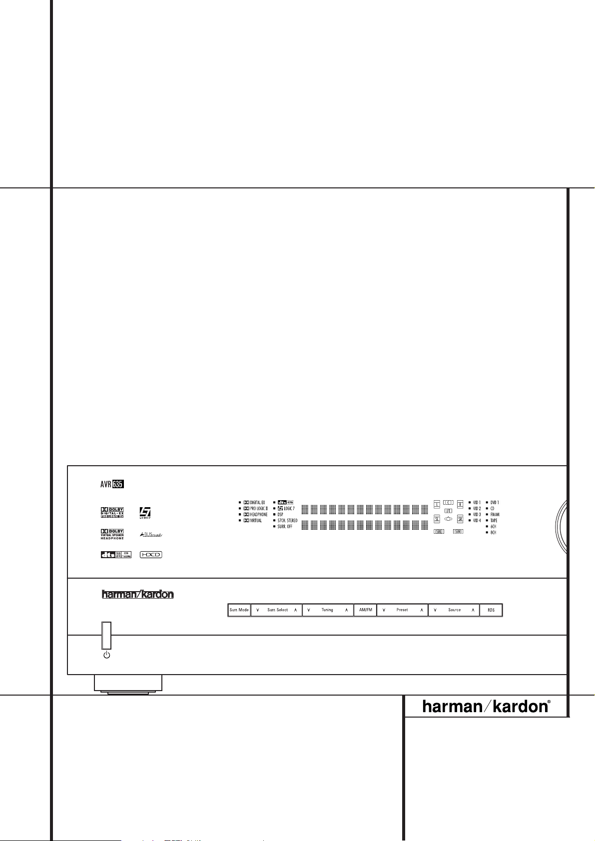
AVR 635 Audio/ VideoReceiver
OWNER’S MANUAL
2 TABLE OF CONTENTS
3 Introduction
4 Safety Information
4 Unpacking
5 Front Panel Controls
7 Rear Panel Connections
10 Main Remote Control Functions
14 Zone II Remote Control Functions
15 Installation and Connections
15 Audio Connections
15 Video Connections
16 SCART A/V Connections
18 System and Power Connections
19 Speaker Selection
19 Speaker Placement
20 System Configuration
20 First Turn On
20 Using the On-Screen Display
20 System Setup
20 Input Setup
22 Audio Setup
22 Surround Setup
23 Night Mode Settings
24 Using EzSet/EQ
26 Manual Setup
27 Speaker Setup
28 Speaker Crossover Setting
29 Delay Settings
30 Output Level Adjustment
32 Additional Input Adjustments
33 Operation
33 Surround Mode Chart
35 Basic Operation
35 Source Selection
35 6/8-Channel Direct Input
35 Controls and Use of Headphones
36 Surround Mode Selection
36 Digital Audio Playback
36 Dolby Digital
37 DTS
37 PCM Audio Playback
37 HDCD
37 MP3 Audio Playback
38 Selecting a Digital Source
38 Digital Bitstream Indicators
38 Speaker/Channel Indicators
39 Night Mode
39 Tape Recording
39 Front Panel Input/Output Connections
40 Output Level Adjustment
With Source Signals
40 Dim Function
40 Memory backup
41 Advanced Features
41 Front Panel Display Fade
41 Display Brightness
41 Turn-On Volume Level
41 Semi-OSD Settings
42 Full-OSD Time Out Adjustment
42 Digital Auto-Poll Settings
42 Multiroom Operation
44 Tuner Operation
44 Basic Tuner Operation
44 Station Selection
44 Preset Tuning
45 RDS Operation
45 RDS Tuning
45 RDS Display Options
45 Program Search
Table of Contents
Typographical Conventions
In order to help you use this manual with the remote control, front-panel controls and rear-panel
connections, certain conventions have been used.
EXAMPLE – (bold type) indicates a specific remote control or front-panel button, or rear-panel
connection jack
EXAMPLE – (OCR type) indicates a message that is visible on the front-panel information display
EXAMPLE – (Synchro type) indicates a message that is displayed on the remote control’s LCD screen
1
– (number in a square) indicates a specific front-panel control
– (number in a circle) indicates a rear-panel connection
0
– (number in an oval) indicates a button or indicator on the remote
å
– (letter in an oval) indicates a button on the Zone II remote
46 Programming the Remote
46 Preprogrammed Code Entry
46 Configuring the Remote
47 Automatic Code Entry
47 Learning Commands
48 Learning Remote Codes for an Input
Selector
48 Device Priority
48 Changing Devices
49 Macro Programming
51 Punch-Through Configuration
52 Renaming
54 Resetting the Remote
54 Backlight Options
56 Troubleshooting Guide
56 Processor Reset
57 Technical Specifications
Declaration of Conformity
We, Harman Consumer Group International
2, route de Tours
72500 Château-du-Loir,
FRANCE
declare in own responsibility, that the product described
in this owner’s manual is in compliance with technical
standards:
EN 55013:2001+A1:2003
EN 55020:2002+A1:2003
EN 61000-3-2:2000
EN 61000-3-3.1995+A1:2001
EN 60065:2002
Jurjen Amsterdam
Harman Consumer Group International
01/05
The appearance of the text or cursor for your receiver’s on-screen menus may vary slightly from the
illustrations in this manual. Whether the text appears in all uppercase or upper- and lowercase
characters, performance and operation remain the same.

INTRODUCTION 3
Introduction
Thank you for choosing Harman Kardon!
With the purchase of a Harman Kardon AVR 635
you are about to begin many years of listening
enjoyment.
Designed to provide all the excitement and detail
of movie soundtracks and every nuance of musical selections, the AVR 635 is truly a multichannel receiver for the new millennium. In addition
to the traditional 5.1 digital decoding modes
such as Dolby Digital and DTS, it offers the latest
advancements in surround technology such as
Dolby Pro Logic IIx, the full suite of DTS-ES 6.1
modes, DTS Neo:6 and the latest 7.1 channel
versions of Harman's own Logic 7 technology.
The AVR 635 has been engineered so that it is
easy to take advantage of all the power of its
digital technology.To obtain the maximum
enjoyment from your new receiver, we urge you
to read this manual. A few minutes spent
learning the functions of the various controls
will enable you to take advantage of all the
power the AVR is able to deliver.
If you have any questions about this product, its
installation or its operation, please contact your
retailer or custom installer. They are your best
local sources of information.
Description and Features
The AVR 635 is among the most versatile and
multifeatured A/V receivers available, incorporating a wide range of listening options. In addition
to Dolby Digital and DTS decoding for digital
sources, a broad choice of surround modes for
Matrix surround-encoded or Stereo recordings
are available for use with sources such as CD,
VCR, TV broadcasts and the AVR’s own FM/AM
tuner. Along with Dolby Digital EX, DTS-ES
®
,
Dolby Pro Logic IIx, DTS Neo:6, Dolby 3 Stereo,
5 Channel or 7 Channel Stereo and Hall and
Theater modes, the AVR 635 offers Harman
International’s exclusive Logic 7 process in both
5.1 and 7.1 versions to create a wider, more
enveloping field environment and more defined
fly-overs and pans.Although the AVR 635’s
primary use will be in multichannel systems,
advanced technology is at work even when only
two speakers are used. Dolby Virtual Speaker is
available to create enveloping sound fields from
front left and right speakers, and the latest Dolby
Headphone circuitry creates an amazing sense of
openness with headphones.
Two-channel listening with analog sources is
available with full bass management or in a traditional “bypass” mode that creates a straight
signal path from the gain stage to the volume
control.
Finally, the AVR is among the very few A/V
receivers that offer decoding of MP3 data, so
that you may listen to the latest music selections
directly from compatible computers or playback
devices with the power and fidelity you expect
from Harman Kardon.
The AVR is also featuring HDCD
®
decoding to
provide the most realistic playback of CDs when
a digital connection is used, even with a normal
non-HDCD-compatible CD or DVD player.
An important addition to the AVR 635’s impressive list of features is EzSet/EQ,™ which automates the configuration process to make it
quicker, easier and more precise. Using the special microphone supplied with the unit, EzSet/EQ
takes the guesswork out of entering speaker
“size” and crossover information, delay times for
all channels and output levels. In addition to the
configuration settings, EzSet/EQ also includes
room equalization so that the signals sent to
each speaker are tailored to provide accurate
sonic quality with your specific combination of
speaker type, room size and other factors that
influence room acoustics.With EzSet/EQ, your
system is custom-configured in a few minutes
with accuracy that previously required expensive
and hard-to-use test equipment.
In tandem with EzSet/EQ, the AVR 635 includes a
full set of manual configuration settings for
those who wish to custom-trim their system even
further. A Quadruple Crossover bass management system makes it possible to enter different
crossover settings for each speaker group.
Video connections and system integration is a
snap with the AVR 635, thanks to format crossconversion which allows any video input to be
output as a high-quality component signal, complete with the AVR’s on-screen menus. For those
sources already in component form, three assignable, wide-bandwidth inputs are available, and
the Video inputs are renameable.To further
enhance the viewing experience with digital
sources or displays, the AVR 635’s A/V Sync
Delay feature allows you to compensate for the
loss of lip sync due to digital video delays individually for each input. Full-carrier IR outputs, a
bi-directional RS-232 port and a learning remote
with a two-line display are among the many
other features that make the AVR 635’s power
simple to use.
Coax and optical digital outputs are available for
direct connection to digital recorders, and both
the front panel analog audio/video and coaxial
digital jacks may be switched to outputs for use
with portable recorders – a Harman Kardon
exclusive.Two video recording outputs, preampout and a color-coded eight-channel input make
the AVR virtually future-proof, with everything
needed to accommodate tomorrow’s new formats right on board.
The AVR 635’s flexibility and power extend
beyond your main home theater or listening
room. The AVR includes a sophisticated multizone control system that allows you to select
one source for use in the main room and a different one (Audio only) in a second room.
Complete control over volume is possible with a
separate infrared control link.To make it easy to
operate the AVR from a remote room, a separate
“Zone II” remote is included.
Additional multiroom options include the option
to assign two of the AVR’s output channels to the
multiroom system and the ability to link the AVR
to innovative A-BUS
®
keypads for multiroom oper-
ation without the need for external amplifiers.
The AVR 635’s powerful amplifier uses traditional
Harman Kardon high-current design technologies
to meet the wide dynamic range of any program
selection.
Harman Kardon invented the high-fidelity
receiver more than fifty years ago.With
state-ofthe-art circuitry and time-honored circuit designs,
the AVR is the perfect combina
tion of the latest in
digital audio technology, a
quiet yet powerful
analog amplifier in an
elegant, easy-to-use
package.
■ Dolby* Digital, Dolby Digital EX and
Dolby Pro Logic* IIx Decoding, and the
full suite of DTS
®
modes, including
DTS-ES
®
6.1 Discrete & Matrix and
Neo:6
®
and DTS 96/24
■ Seven channels of high-current amplifi-
cation with two channels assignable to
either surround back or multiroom
applications
■ Harman Kardon’s exclusive Logic 7
®
processing, along with a choice of
Dolby Virtual Speaker processing for
use when only two speakers are
available
■ Dolby Headphone to create spacious,
open sound fields when using headphones
■ MP3 decoding for use with compatible
computers and digital audio players
■ Harman Kardon’s advanced EzSet/EQ™
automatically configures speaker settings and sets room equalization for
quick, easy and accurate system setup
■ High-bandwidth, HDTV-compatible com-
ponent video switching
, HDCD®, High Definition Compatible Digital®and Pacific Microsonics™are either registered trademarks or trademarks of Pacific Microsonics, Inc., in the United
States and/or other countries. HDCD System manufactured under license from Pacific Microsonics, Inc.
4 INTRODUCTION / SAFETY INFORMATION
Introduction / Safety Information
■ Precision video cross-conversion circuitry outputs any video input on the component outputs, complete with onscreen system menus
■ Front panel analog A/V inputs, switchable to outputs
■ Front panel digital inputs with coax
digital output capability for easy connection to portable digital devices and
the latest video game consoles
■ Multiple digital inputs and outputs
■ On-screen menu and display system
■ Extensive multiroom options, including
a standard Zone II remote, assignable
amplifier channels and A-BUS Ready
®
capability for listening to a separate
source in a remote zone
■ 6-Channel/8-Channel Direct Input and
Preamp Outputs for Easy Expansion and
Use with Future Audio Formats
■ Extensive bass management options,
6/8-channel direct inputs for use with
DVD-Audio or SACD players, including
Quadruple Crossover and individual
settings for each input
■ A/V Sync delay adjustable for each
input delivers perfect lip sync with
digital programs or video displays
■ Main Backlit Remote with Internal
Codes and Learning Capability
■ HDCD Decoding for Superb
CD Playback
Important Safety Information
Verify Line Voltage Before Use
Your AVR 635 has been designed for use with
220-240-Volt AC current. Connection to a line
voltage other than that for which it is intended
can create a safety and fire hazard and may
damage the unit.
If you have any questions about the voltage
requirements for your specific model, or about
the line voltage in your area, contact your dealer
before plugging the unit into a wall outlet.
Do Not Use Extension Cords
To avoid safety hazards, use only the power cord
attached to your unit. We do not recommend
that extension cords be used with this product.
As with all electrical devices, do not run power
cords under rugs or carpets or place heavy
objects on them. Damaged power cords should
be replaced immediately by an authorized service depot with a cord meeting factory specifications.
Handle the AC Power Cord Gently
When disconnecting the power cord from an AC
outlet, always pull the plug, never pull the cord.
If you do not intend to use the unit for any
considerable length of time, disconnect the plug
from the AC outlet.
Do Not Open the Cabinet
There are no user-serviceable components inside
this product. Opening the cabinet may present a
shock hazard, and any modification to the product will void your guarantee. If water or any
metal object such as a paper clip, wire or a
staple accidentally falls inside the unit, disconnect it from the AC power source immediately,
and consult an authorized service station.
Installation Location
■ To assure proper operation and to avoid the
potential for safety hazards, place the unit on
a firm and level surface.When placing the
unit on a shelf, be certain that the shelf and
any mounting hardware can support the
weight of the product.
■ Make certain that proper space is provided
both above and below the unit for ventilation.
If this product will be installed in a cabinet or
other enclosed area, make certain that there
is sufficient air movement within the cabinet.
Under some circumstances a fan may be
required.
■ Do not place the unit directly on a carpeted
surface.
■ Avoid installation in extremely hot or cold
locations, or an area that is exposed to direct
sunlight or heating equipment.
■ Avoid moist or humid locations.
■ Do not obstruct the ventilation slots on the
top of the unit, or place objects directly over
them.
Cleaning
When the unit gets dirty, wipe it with a clean,
soft, dry cloth. If necessary, wipe it with a soft
cloth dampened with mild soapy water, then a
fresh cloth with clean water. Wipe dry immediately with a dry cloth. NEVER use benzene,
aerosol cleaners, thinner, alcohol or any other
volatile cleaning agent. Do not use abrasive
cleaners, as they may damage the finish of metal
parts.Avoid spraying insecticide near the unit.
Moving the Unit
Before moving the unit, be certain to disconnect
any interconnection cords with other components, and make certain that you disconnect the
unit from the AC outlet.
Unpacking
The carton and shipping materials used to protect your new receiver during shipment were
specially designed to cushion it from shock and
vibration. We suggest that you save the carton
and packing materials for use in shipping if you
move, or should the unit ever need repair.
To minimize the size of the carton in storage,
you may wish to flatten it. This is done by carefully slitting the tape seams on the bottom and
collapsing the carton. Other cardboard inserts
may be stored in the same manner. Packing
materials that cannot be collapsed should be
saved along with the carton in a plastic bag.
If you do not wish to save the packaging materials, please note that the carton and other sections of the shipping protection are recyclable.
Please respect the environment and discard
those materials at a local recycling center.
FRONT PANEL CONTROLS 5
1
Main Power Switch: Press this button to
apply power to the AVR. When the switch is
pressed in, the unit is placed in a Standby
mode, as indicated by the orange LED
3
surrounding the System Power Control2.
This button MUST be pressed in to operate the
unit. To turn the unit off completely and prevent
the use of the remote control, this switch
should be pressed until it pops out from the
front panel so that the word “OFF” may be
read at the top of the switch.
NOTE: This switch is normally left in the “ON”
position.
2
System Power Control: When the Main
Power Switch
1
is “ON,” press this button to
turn on the AVR; press it again to turn the unit
off (to Standby). Note that the Power Indicator
surrounding the switch
3
will turn blue when
the unit is on.
3
Power Indicator: This LED will be
illuminated in orange when the unit is in the
Standby mode to signal that the unit is ready to
be turned on. When the unit is in operation, the
indicator will turn blue.
4
Headphone Jack: This jack may be used to
listen to the AVR’s output through a pair of headphones. Be certain that the headphones have a
standard 6.3 mm stereo phone plug. Note that
the main room speakers and all Preamp
Outputs
will automatically be turned off
when the headphone jack is in use.
5
Surround Mode Group Selector: Press this
button to select the top-level group of surround
modes. Each press of the button will select a
major mode grouping in the following order:
Dolby Modes ➜ DTS Digital Modes ➜ DSP
Modes ➜ Stereo Modes ➜ Logic 7 Modes
Once the button is pressed so that the name of
the desired surround mode group appears in the
on-screen display and in the Lower Display Line
˜
, press the Surround Mode Selector9to
cycle through the individual modes available. For
example, press this button to select Dolby modes,
and then press the Surround Mode Selector
9
to choose from the various mode options.
6
Speaker Selector: Press this button to
begin the process of configuring the AVR for the
type of speakers it is being used with. For complete information on configuring the speaker settings using the front-panel controls see page 27.
7‹Button: When an adjustment is being
made using the Channel Select
Ù
or Digital
Select
Û
buttons, this button may be pressed
to scroll through the available options.
8
Tone Mode: Pressing this button enables or
disables the Balance, Bass and Treble tone
controls.When the button is pressed so that the
words
TONE IN appear in the Main Infor-
mation Display
˜
, the settings of the Bass
and Treble controls and of the Balance control
will affect the output signals.When the button is
pressed so that the words
TONE OUT appear
in the Main Information Display
˜
, the
output signal will be “flat,” without any balance,
bass or treble alteration, no matter how the
actual Controls are adjusted. (For more information, see page 22).
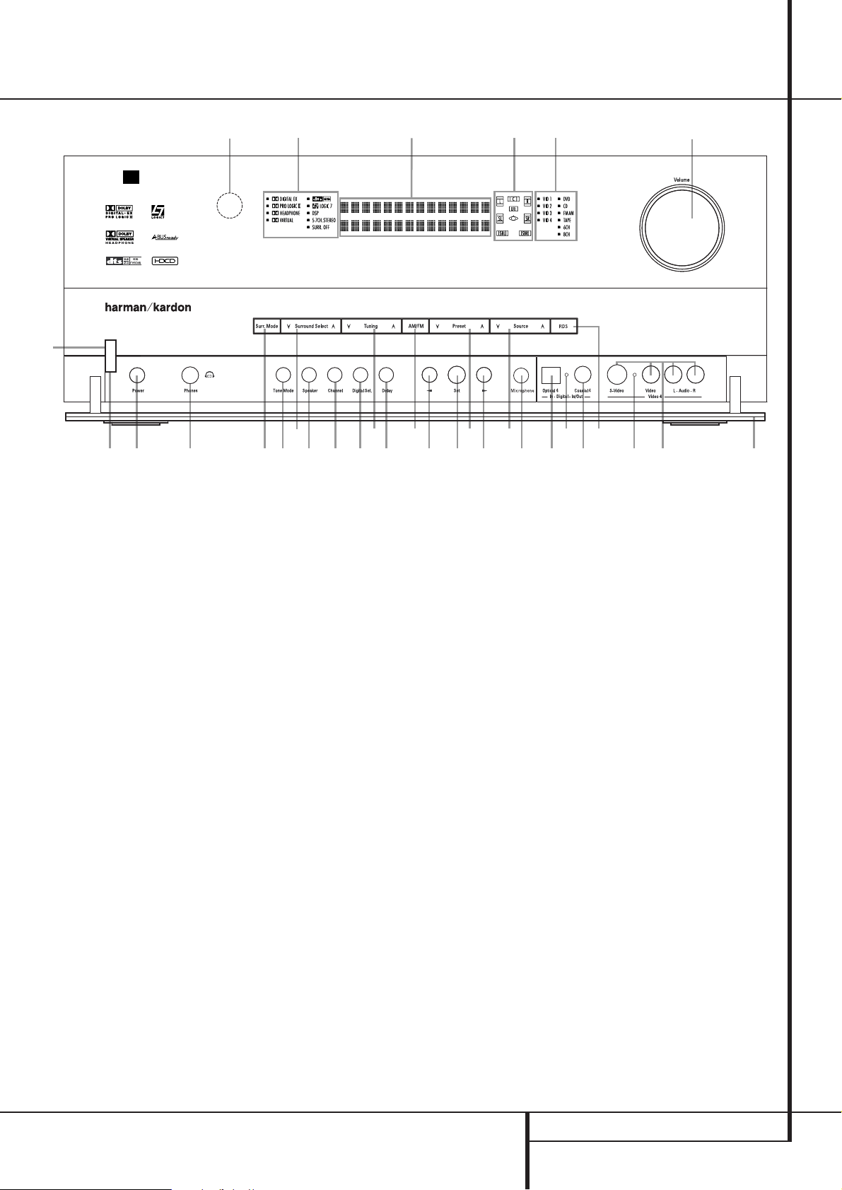
Front Panel Controls
1
2
3
4
5
6
7
8
9
)
!
@
#
$
%
^
&
*
(
Ó
Ô
Ò
Ú
Û
Ù
ı
ˆ
˜
¯
˘
Main Power Switch
System Power Control
Power Indicator
Headphone Jack
Surround Mode Group Selector
Speaker Selector
‹
Button
Tone Mode
Surround Mode Selector
Tuning Selector
Tuner Band Selector
Set Button
Preset Station Selector
›
Button
Input Source Selector
RDS Selector
Delay Adjust Selector
Digital Optical 4 Input
Input/Output Status Indicators
Digital Coax 4 Jack
Video 4 Input/Output Jacks
Front Panel Control Door
Surround Mode Indicators
Speaker/Channel Input Indicators
Digital Select Button
Channel Select Button
Volume Control
Input Indicators
Main Information Display
Remote Sensor Window
EzSet/EQ Microphone Jacks
AVR 635
3
2
1 4
¯
Ò
˜
Ú ˆ
9)! # % ( ^
5 8
6 Ù Û & 7 @ $ U * Ó ( Ô
ı

6 FRONT PANEL CONTROLS
Front Panel Controls
9
Surround Mode Selector: Press this
button to cycle through the individual surround
modes available after the Surround Mode
Group Selector
5
was pressed (see item
5
above). Note that depending on the type of
input, some modes are not always available. (See
page 36 for more information about surround
modes).
)
Tuning Selector: Press the left side of the
button to tune lower frequency stations and the
right side of the button to tune higher frequency
stations.When a station with a strong signal is
reached,
MANUAL TUNED or AUTO
TUNED
will appear in the Main Information
Display
˜
(see page 44 for more information
on tuning stations).
!
Tuner Band Selector: Pressing this button
will automatically switch the AVR to the Tuner
mode. Pressing it again will switch between the
AM and FM frequency bands, holding it pressed
for some seconds will switch between stereo and
mono receiving and between automatic and
manual tuning mode (See page 44 for more
information on the tuner).
@
Set Button: When making choices during
the setup and configuration process, press this
button to enter the desired setting as shown in
the Main Information Display
˜
into the
AVR’s memory.
#
Preset Stations Selector: Press this
button to scroll up or down through the list of
stations that have been entered into the preset
memory. (See page 44 for more information on
tuner programming.)
$›Button: When an adjustment is being
made using the Channel Select
Ù
or Digital
Select
Û
buttons, this button may be pressed
to scroll through the available options.
%
Input Source Selector: Press this button to
change the input by scrolling through the list of
input sources.
^ RDS Select Button: Press this button to dis-
play the various messages that are part of the RDS
data system of the AVR’s tuner. (See page 45 for
more information on RDS).
& Delay Adjust Selector: Press this button to
begin the process of adjusting the delay settings
for Dolby surround modes. See page 29 for more
information on delay adjustments.
*
Digital Optical 4 Input: Connect the optical
digital audio output of an audio or video product
to this jack. When the Input is not in use, be
certain to keep the plastic cap installed to avoid
dust contamination that might degrade future
performance.
(
Input/Output Status Indicators: These
LED indicators will normally light green to show
that the front panel Video 4 A/V
Ô
jacks or the
Coaxial 4 digital
Ó
jack is operating as an
input. When either of these jacks has been configured for use as an output, the indicator will
turn red to show that the jack may be used for
recording. (See page 39 for more information on
configuring the front panel jacks as outputs,
rather than inputs.)
Ó
Digital Coax 4 Jack: This jack is normally
used for connection to the output of portable
audio devices, video game consoles or other
products that have a coax digital jack. It may
also be configured as an output jack, to feed a
digital signal to a CD-R, MiniDisc or other digital
recording device. (See page 21 for information
on configuring the Digital Coax 4 Jack to an
output.)
Ô
Video 4 Input/Output Jacks: These
audio/video jacks may be used for temporary
connection to video games or portable audio/
video products such as camcorders and portable
audio players.They may also be configured as
output jacks (also S-Video) to feed a signal to
any recording Audio or Video device (see page 39
for more information).
Front-Panel Control Door:To open the
door so that the front-panel jacks and controls
behind this door may be accessed, gently pull the
door down and towards you using either upper
corner of the door.
Ò
Surround Mode Indicators: The current
selected mode or function will appear as one of
these indicators. Note that when the unit is
turned on, the entire list of available modes will
light briefly, and then revert to normal operation
with only the active mode indicator illuminated.
Ú
Speaker/Channel Input Indicators: These
indicators are multipurpose, indicating either the
speaker type selected for each channel or the
incoming data-signal configuration.The left,center,
right, right surround and left surround speaker
indicators are composed of three boxes, while the
subwoofer is a single box. The center box lights
when a “Small” speaker is selected, and the two
outer boxes light when “Large” speakers are
selected. When none of the boxes are lit for the
center, surround or subwoofer channels, no speaker
has been selected for that position. (See page 27
for more information on configuring speakers.) The
letters inside each of the center boxes display
active input channels. For standard analog inputs,
only the L and R will light, indicating a stereo
input. When a digital source is playing, the indicators will light to display the channels begin
received at the digital input. When the letters
flash, the digital input has been interrupted. (See
page 38 for more information on the Channel
Indicators).
Û
Digital Select Button: When playing a
source that has a digital output, press this button
to select between the Optical
*
and
Coaxial
Ó
Digital inputs (See page 36 for
more information).
Ù
Channel Select Button: Press this button
to begin the process of trimming the channel
output levels using an external audio source.
(For more information on output level trim
adjustment, see page 40).
ı
Volume Control:Turn this knob clockwise
to increase the volume, counterclockwise to
decrease the volume. If the AVR is muted,
adjusting volume control will automatically
release the unit from the silenced condition.
ˆ
Input indicators: The current selected
mode or function will appear as one of these
indicators. Note that when the unit is turned on,
the entire list of available modes will light briefly,
and then revert to normal operation with only
the active mode indicator illuminated.
˜
Main Information Display: This display
delivers messages and status indications to help
you operate the receiver.
¯
Remote Sensor Window:The sensor
behind this window receives infrared signals from
the remote control. Aim the remote at this area
and do not block or cover it unless an external
remote sensor is installed.
˘
EzSet/EQ Microphone Jack: Before
starting the EzSet/EQ automated setup process,
plug the microphone into this jack. The
microphone does not need to be plugged in at
other times.
REAR PANEL CONNECTIONS 7
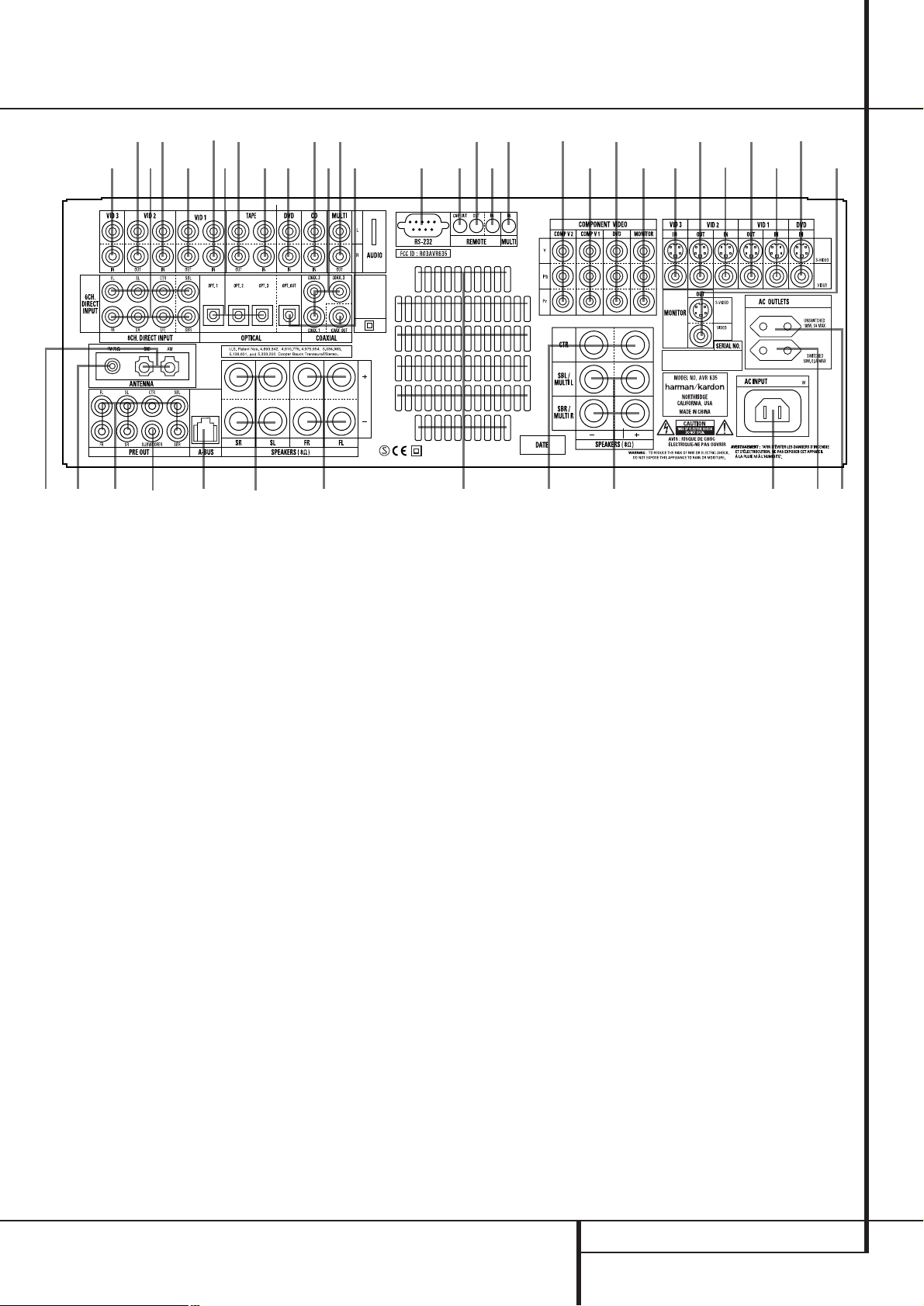
Rear Panel Connections
AM Antenna
FM Antenna
Tape Inputs
Tape Outputs
Subwoofer Output
DVD Audio Inputs
CD Inputs
Multiroom Outputs
A-BUS Connector
8-Channel Direct Inputs
Digital Audio Outputs
Video Monitor Outputs
DVD Video Inputs
Front Speaker Outputs
Center Speaker Outputs
Surround Speaker Outputs
Switched AC Accessory Outlet
Unswitched AC Accessory Outlet
AC Power Cord Jack
Video 2 Component Video Inputs
Component Video Outputs
Video 1 Component Video Inputs
Remote IR Output
Remote IR Input
Multiroom IR Input
Video 1 Video Outputs
Video 1 Video Inputs
Video 2 Video Outputs
Video 3 Video Inputs
Video 2 Video Inputs
Optical Digital Inputs
Coaxial Digital Inputs
Video 2 Audio Outputs
Video 2 Audio Inputs
Video 3 Audio Inputs
Video 1 Audio Inputs
Video 1 Audio Outputs
Preamp Outputs
Surround Back/Multiroom Speaker Outputs
RS-232 Port
Fan Vents
DVD Component Video Inputs
Remote IR Carrier Output
NOTE: To assist in making the correct connections for multichannel input/output and speaker
connections, all connection jacks and terminals
have been color coded in conformance with the
latest CEA standards as follows:
Front Left: White
Front Right: Red
Center: Green
Surround Left: Blue
Surround Right: Gray
Surround Back Left: Brown
Surround Back Right: Tan
Subwoofer (LFE): Purple
Digital Audio: Orange
Composite Video: Yellow
Component Video “Y”: Green
Component Video “Pr”: Red
Component Video “Pb”: Blue
AM Antenna: Connect the AM loop antenna
supplied with the receiver to these terminals. If an
external AM antenna is used, make connections to
the AM and GND terminals in accordance with
the instructions supplied with the antenna.
FM Antenna: Connect the supplied indoor or
an optional external FM antenna to this terminal.
Tape Inputs: Connect these jacks to the
PLAY/OUT jacks of an audio recorder.
Tape Outputs: Connect these jacks to the
RECORD/INPUT jacks of an audio recorder.
Subwoofer Output: Connect this jack to
the line-level input of a powered subwoofer. If an
external subwoofer amplifier is used, connect this
jack to the subwoofer amplifier input.
DVD Audio Inputs: Connect these jacks to
the analog audio jacks on a DVD or other audio
or video source.
CD Inputs: Connect these jacks to the
analog output of a compact disc player or CD
changer or any other audio source.
Multiroom Outputs: Connect these jacks
to an optional audio power amplifier to listen to
the source selected by the multiroom system in a
remote room.
A-BUS Connector: Connect this jack to an
optional A-BUS-certified remote room keypad or
amplifier to extend the multiroom capabilities of
your AVR. See page 18 for more information on
A-BUS.
8-Channel Direct Inputs: These jacks are
used for connection to source devices such as
DVD-Audio or SACD players with discrete analog
outputs. Depending on the source device in use,
all eight jacks may be used, though in many
cases only connections to the front left/right,
center, surround left/right and LFE (subwoofer
input) jacks will be used for standard 5.1 audio
signals.
Digital Audio Outputs: Connect these
jacks to the matching digital input connector on
a digital recorder such as a CD-R or MiniDisc
recorder.
~230V/50Hz
230 V/50Hz

8 REAR PANEL CONNECTIONS
Rear Panel Connections
Video Monitor Outputs: Connect this jack
to the composite and/or S-Video input of a TV
monitor or video projector to view the on-screen
menus and the output of any standard Video or
S-Video source selected by the receiver’s video
switcher.
DVD Video Inputs: Connect these jacks to
the composite or S-Video output jacks on a DVD
player or other video source.
Front Speaker Outputs: Connect these
outputs to the matching + or – terminals on
your left and right speakers. In conformance with
the new CEA color code specification, the White
terminal is the positive, or "+" terminal that
should be connected to the red (+) terminal on
Front Left speaker with the older color coding,
while the Red terminal is the positive, or "+"
terminal that should be connected to the red (+)
terminal on Front Right speaker. Connect the
black (–) terminals on the AVR to the black (–)
terminals on the speakers. See page 15 for more
information on speaker polarity.
Center Speaker Outputs: Connect these
outputs to the matching + and – terminals on
your center channel speaker. In conformance
with the new CEA color code specification, the
Green Terminal is the positive, or "+" terminal
that should be connected to the red (+) terminal
on speakers with the older color coding. Connect
the black (–) terminal on the AVR to the black
negative (–) terminal on your speaker. (See page
15 for more information on speaker polarity.)
Surround Speaker Outputs: Connect
these outputs to the matching + and – terminals
on your surround channel speakers. In conformance with the new CEA color code specification, the Blue terminal is the positive, or "+"
terminal that should be connected to the red (+)
terminal on the Surround Left speaker with older
color coding, while the Gray terminal should be
connected to the red (+) terminal on the
Surround Right speaker with the older color coding. Connect the black (–) terminal on the AVR
to the matching black negative (–) terminals for
each surround speaker. (See page 15 for more
information on speaker polarity.)
Switched AC Accessory Outlet: This outlet may be used to power any device that you
wish to have turn on when the AVR is turned on
with the System Power Control switch
2
.
Unswitched AC Accessory Outlet: This
outlet may be used to power any AC device. The
power will remain on at this outlet regardless of
whether the AVR is on or off.
Note: The total power consumption of all
devices connected to the accessory outlets
should not exceed 100 watts from the
Unswitched Outlet
and 50 W from the
Switched Outlet
.
AC Power Cord Jack: Connect the AC
power cord to this jack when the installation is
complete.To ensure safe operation, use only the
power cord supplied with the unit. If a replacement is required it must be of the same type and
capacity.
Component Video 2 Inputs:These inputs
may be used with any video source device
equipped with analog Y/Pr/Pb or RGB component video outputs.The factory default is for
these jacks to be a linked to the Video 2 input,
but you may change the setting at any time
through the
IN/OUT SETUP menu. See
page 15 for more information on configuring the
component video inputs.
Monitor Component Video Outputs:
Connect these outputs to the component video
inputs of a video projector or monitor. When a
source connected to one of the two
Component Video Inputs
is selected
the signal will be sent to these jacks.
Component Video 1 Inputs:These inputs
may be used with any source device equipped
with analog Y/Pr/Pb or RGB component video
outputs.The factory default is for these jacks to
be a linked to the Video 1 input, but you may
change the setting at any time through the
IN/OUT SETUP menu. See page 15 for
more information on configuring the component
video inputs.
Note: All component inputs/outputs can be
used for RGB signals too, in the same way as
described for the Y/Pr/Pb signals, then connected
to the jacks with the corresponding color.
RGB connection is not possible if the source outputs a separate sync signal (see page 16).
Remote IR Output: This connection permits
the IR sensor in the receiver to serve other
remote controlled devices. Connect this jack to
the “IR IN” jack on Harman Kardon or other
compatible equipment.
Remote IR Input: If the AVR’s front-panel
IR sensor is blocked due to cabinet doors or
other obstructions, an external IR sensor may
be used. Connect the output of the sensor to
this jack.
Multiroom IR Input: Connect the output of
an IR sensor in a remote room to this jack to
operate the AVR’s multiroom control system.
Video 1 Video Outputs: Connect these
jacks to the RECORD/INPUT composite or
S-Video jack on a VCR.
Video 1 Video Inputs: Connect these jacks
to the PLAY/OUT composite or S-Video jacks on
a VCR or other video source.
Video 2 Video Outputs: Connect these
jacks to the RECORD/INPUT composite or
S-Video jacks on a second VCR.
Video 3 Video Inputs: Connect these jacks
to the PLAY/OUT composite or S-Video jacks on
any video source.
Video 2 Video Inputs: Connect these jacks
to the PLAY/OUT composite or S-Video jacks on
a second VCR or other video source.
Optical Digital Inputs: Connect the
optical digital output from a DVD player, HDTV
receiver, the S/PDIF output of a compatible computer sound card playing MP3 files or streams,
LD player, MD player or CD player to these jacks.
The signal may be either a Dolby Digital signal, a
DTS signal, a 2 channel MPEG 1 signal, an MP3
or HDCD data stream or a standard PCM digital
source.
Coaxial Digital Inputs: Connect the coax
digital output from a DVD player, HDTV receiver,
the S/PDIF output of a compatible computer
sound card playing MP3 files or streams, LD
player, MD player or CD player to these jacks.
The signal may be either a Dolby Digital signal,
DTS signal, a 2 channel MPEG 1 signal, an MP3
or HDCD data stream or a standard PCM digital
source. Do not connect the RF digital output of
an LD player to these jacks.
Video 2 Audio Outputs: Connect these
jacks to the RECORD/INPUT audio jacks on a
VCR or any Audio recorder.
Video 2 Audio Inputs: Connect these jacks
to the PLAY/OUT audio jacks on a second VCR
or other audio or video source.
Video 3 Audio Inputs: Connect these jacks
to the PLAY/OUT audio jacks on any audio or
video source.
Video 1 Audio Inputs: Connect these jacks
to the PLAY/OUT audio jacks on a VCR or other
audio or video source.
Video 1 Audio Outputs: Connect these
jacks to the RECORD/INPUT audio jacks on
a VCR or any other Audio recorder.

REAR PANEL CONNECTIONS 9
Preamp Outputs: Connect these jacks to
an optional, external power amplifier for applications where higher power is desired.
Surround Back/Multiroom Speaker
Outputs: These speaker terminals are normally
used to power the surround back left/surround
back right speakers in a 7.1 channel system.
However, they may also be used to power the
speakers in a second zone, which will receive the
output selected for a multiroom system.
To change the output fed to these terminals
from the default of the Surround Back speakers
to the Multiroom Output, you must change a
setting in the Multiroom Menu of the OSD system. See page 42 for more information on configuring this speaker output. In normal surround
system use, the brown and black terminals are
the surround back left channel positive (+) and
negative (–) connections and the tan and black
terminals are the surround back right positive
(+) and negative (–) terminals.
For multiroom use, connect the brown and black
SBL terminals to the red and black connections
on the left remote zone speaker and connect the
tan and black SBR terminals to the red and black
terminals on the right remote zone speaker.
RS-232 Port: This jack may be used to control the AVR 635 over a bi-directional RS-232
serial control link to a compatible computer or
programmable remote control system. Due to
the complexity of programming RS-232 commands we strongly recommend that connections
to this port for control purposes be made by a
trained and qualified technician. This jack may
also link to a compatible computer to upgrade
the software and operating system of the
AVR 635 when appropriate upgrades are
available.
Fan Vents: These ventilation holes are the
output of the AVR’s airflow system. To ensure
proper operation of the unit and to avoid possible damage to delicate surfaces, make certain
that these holes are not blocked and that there
is at least three inches of open space between
the vent holes and any wooden or fabric surface.
DVD Component Video Inputs: These
inputs may be used with any source device
equipped with analog Y/Pr/Pb or RGB component video outputs.The factory default is for
these jacks to be a linked to the DVD input, but
you may change the setting at any time through
the
IN/OUT SETUP menu. See page 15 for
more information on configuring the component
video inputs.
Remote IR Carrier Output: The output of
this jack is the full signal received at the
Remote Sensor Window
¯
or input through
the Remote IR Input
including the carrier
frequency that is removed from signals at the
Remote IR Output
. Use this output to
extend IR remote signals to the input of
compatible products by direct connection or
through the use of optional, external IR
“blasters”. If you are in doubt as to which of the
two IR Output jacks to use, we recommend that
you consult with your dealer or installer, or check
with the manufacturer of the external equipment
you wish to control.
Rear Panel Connections
0
1
2
3
4
5
6
7
8
9
A
B
C
D
E
F
G
H
I
J
K
L
M
N
O
P
Q
10 MAIN REMOTE CONTROL FUNCTIONS
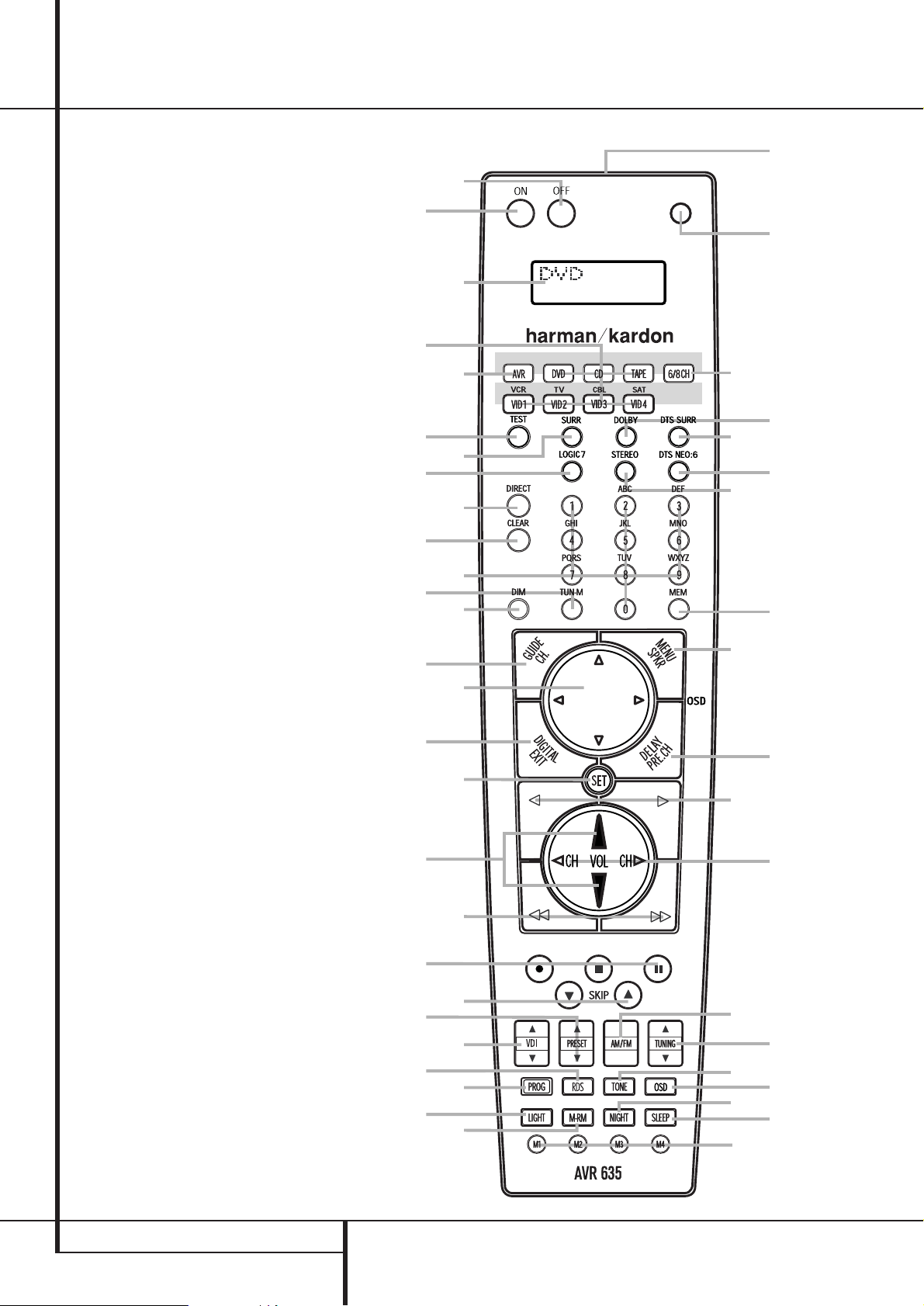
Main Remote Control Functions
Power Off Button
IR Transmitter Window
LCD Information Display
Power On Button
Input Selectors
AVR Selector
AM/FM Tuner Select
6-Channel/8-Channel Direct Input
Test Button
Sleep Button
Surround Mode Selector
Night Mode
Channel Select Button
Dim Button
Navigation Button
Set Button
Digital Select
Numeric Keys
Tuner Mode
Direct Button
Tuning Up/Down
OSD Button
Dolby Mode Select Button
DTS Digital Mode Selector
Logic 7 Mode Select Button
Transport Controls
Light Button
Skip Up/Down Buttons
Stereo Mode Select Button
DTS Neo:6 Mode Select
Macro Buttons
RDS Selector Button
Preset Up/Down
Clear Button
Memory Button
Delay/Prev. Ch.
Program Button
Speaker Select
Multiroom
Volume Up/Down
Video Input Button
Channel Up/Down Selector
Mute
Tone Control Button
NOTE: The function names shown here are each
button’s feature when used with the AVR. Most
buttons have additional functions when used
with other devices.
The jack on the upper right side of the remote is
reserved for future use. Do not remove the plug
provided or connect any device to the jack.
3
4
8
O
I
C
G
0
2
5
A
J
H
D
E
F
1
MUTE
7
M
N
P
P
Q
P
6
K
L
B
9
MAIN REMOTE CONTROL FUNCTIONS 11
Main Remote Control Functions
IMPORTANT NOTE: The AVR 635’s remote may
be programmed to control up to seven devices,
including the AVR. Before using the remote, it is
important to remember to press the Input
Selector button
4
that corresponds to the
unit you wish to operate. In addition, the AVR’s
remote is shipped from the factory to operate the
AVR and most Harman Kardon CD or DVD players and cassette decks.The remote is also capable of operating a wide variety of other products
using the control codes that are part of the
remote or by learning commands from other
remotes. Before using the remote with other
products, follow the instructions on pages 46-49
to program the proper codes for the products in
your system.
It is also important to remember that many of
the buttons on the remote take on different
functions, depending on the product selected
using the Input Selector Button
4
.The
descriptions shown here primarily detail the
functions of the remote when it is used to
operate the AVR.
0
Power Off Button: Press this button to
place the AVR or a selected device unit in the
Standby mode. Note that when the AVR is
switched off this will turn off the main room
functions, but if the Multiroom system is activated,
it will continue to function.
1
IR Transmitter Window: Point this window
towards the AVR when pressing buttons on the
remote to make certain that infrared commands
are properly received.
2
LCD Information Display: This two-line
screen displays various information depending
on the commands that have been entered into
the remote.
3
Power On Button: Press this button to turn
on the power to a device selected by pressing one
of the Input Selectors
4
(except Tape).
4
Input Selectors: Pressing one of these
buttons will perform three actions at the same
time. First, if the AVR is not turned on, this will
power up the unit. Next, it will select the source
shown on the button as the input to the AVR.
Finally, it will change the remote control so that
it controls the device selected. After pressing one
of these buttons you must press the AVR
Selector button
5
again to operate the AVR’s
functions with the remote.
5
AVR Selector: Pressing this button will
switch the remote so that it will operate the AVR’s
functions. If the AVR is in the Standby mode, it will
also turn the AVR on.
6
AM/FM Tuner Select: Press this button to
select the AVR’s tuner as the listening choice.
Pressing this button when the tuner is in use will
select between the AM and FM bands.
7
6-Channel/8 Channel Direct Input:
Press this button to select the device connected
to the 6-Channel Direct Inputs or the
8-Channel Direct Inputs
(the input
available will depend on the selection 5.1 or
6.1/7.1 made in the surround mode setting,
see page 24 for more information).
8
Test Tone: Press this button to begin the
sequence used to calibrate the AVR’s output levels. (See page 27 for more information on calibrating the AVR.)
9
Sleep Button: Press this button to place
the unit in the Sleep mode.After the time shown
in the display, the AVR will automatically go into
the Standby mode. Each press of the button
changes the time until turn-off in the following
order:
Hold the button pressed for two seconds to turn
off the Sleep mode setting.
Note that this button is also used to change
channels on your TV, VCR and Sat receiver when
the appropriate source is selected, using the
device Input Selectors
4
.
A
Surround Mode Selector: Press this button to select any of the HALL, THEATER surround
modes. Note that depending on the type of
input, some modes are not always available. (See
page 33 for more information about surround
modes.) Note that this button is also used to
tune channels on your TV, VCR and Sat receiver
when the appropriate source is selected using
the device Input Selector
4
.
B
Night Mode: Press this button to activate
the Night mode.This mode is available only with
Dolby Digital encoded sources, and it preserves
dialog (center channel) intelligibilty at low volume levels (See page 23 for more information).
C
Channel Select Button: This button is
used to start the process of setting the AVR’s
output levels with an external source. Once this
button is pressed, use the
⁄/¤
buttons Eto
select the channel being adjusted, then press the
Set button
F
, followed by the
⁄/¤
buttons
E
again, to change the level setting. (See page
40 for more information.)
D
Dim Button: Press this button to activate
the Dimmer function, which reduces the brightness of the front-panel display, or turns it off
entirely. Press the button once to change the display to reduce the brightness by 50%, and press
it again within five seconds and the main display
will go completely dark. Note that this setting is
temporary; regardless of any changes, the display
will always return to full brightness when the
AVR is turned on.The blue illumination around
the Standby/On Button
1
will always remain
at full brightness regardless of the setting to
remind you that the AVR is still turned on. The
blue accent lighting inside the volume control
will also remain at full brightness when the
panel is at 50%, but go out when the panel
lights are fully dimmed.
E
Navigation Button: This single disc-like
button is used to change or scroll through items
in the on-screen menus or on the front panel or
to make configuration settings such as digital
inputs or delay timing. When changing a setting,
first press the button for the function or setting
to be changed (e.g., press the Digital Select
Button
G
to change a digital input) and then
press one of these buttons to scroll through the
list of options or to increase or decrease a setting. The sections in this manual describing the
individual features and functions contain specific
information on using these buttons for each
application.
F
Set Button: This button is used to enter
settings into the AVR’s memory. It is also used in
the setup procedures for delay time, speaker configuration and channel output level adjustment.
G
Digital Select: Press this button to assign
one of the digital inputs
*Ó
to a source.
(See page 37 for more information on using
digital inputs.)
H
Numeric Keys: These buttons serve as a
ten-button numeric keypad to enter tuner preset
positions.They are also used to select channel
numbers when TV, VCR or Sat receiver has
been selected on the remote, or to select track
numbers on a CD, DVD or LD player, depending
on how the remote has been programmed.
I
Tuner Mode: Press this button when the
tuner is in use to select between automatic
tuning and manual tuning. When the button is
pressed so
MANUAL appears in the Main
Information Display
˜
, pressing the Tuning
buttons
K)will move the frequency up or
down in single-step increments.When the FM
band is in use and
AUTO appears in the Main
Information Display
˜
, pressing this button
will change to monaural reception making even
week stations audible. (See page 44 for more
information.)
J
Direct Button: Press this button when the
tuner is in use to start the sequence for direct
entry of a station’s frequency. After pressing the
button simply press the proper Numeric Keys
H
to select a station (See page 44 for more
information on the tuner).
90
min80min70min60min50min
40
min
30
min20min10min
OFF
12 MAIN REMOTE CONTROL FUNCTIONS
K
Tuning Up/Down: When the tuner is in use,
these buttons will tune up or down through the
selected frequency band. If the Tuner Mode but-
ton
I
has been pressed or the Band button
!
on the front panel was held pressed so that
AUTO appears in the Main Information
Display
˜
, pressing either of the buttons will
cause the tuner to seek the next station with
acceptable signal strength for quality reception.
When the
MANUAL appears in the Main
Information Display
˜
, pressing these buttons will tune stations in single-step increments.
(See page 44 for more information.)
L
OSD Button: Press this button to activate
the On Screen Display (OSD) system used to set
up or adjust the AVR’s parameters.
M
Dolby Mode Selector: This button is used
to select one of the available Dolby Surround
processing modes. Each press of this button will
select one of the Dolby Pro Logic II modes, Dolby
3 Stereo or Dolby Digital. Note that the Dolby
Digital mode is only available with a digital input
selected and the other modes only as long as a
Dolby Digital source is not playing (except Pro
Logic II with Dolby Digital 2.0 recordings, see
Note on page 7). See page 23 for the available
Dolby surround mode options.
N
DTS Digital Mode Selector: When a DTS
source is in use the AVR will select the appropriate mode automatically and no other mode will
be available. Pressing this button will display the
mode currently selected by the AVR´s decoder,
depending on the surround material played and
the speaker setting (see item
6
, page 5).When
a DTS source is not in use, this button has no
function. (See page 23, 33 for the available DTS
options.)
O
Logic 7 Selector: Press this button to
select one of the available Logic 7 surround
modes. (See page 33 for the available Logic 7
options.)
P
Transport Control Buttons: These buttons do not have any functions for the AVR, but
they may be programmed for the forward/reverse
play operation of a wide variety of CD or DVD
players, and audio or video- cassette recorders.
(See page 46 for more information on programming the remote.)
Q
Light Button: Press this button to activate
the remote’s built-in backlight for better legibility
of the buttons in a darkened room.
Skip Up/Down Buttons: These buttons do
not have a direct function with the AVR, but
when used with a compatibly programmed CD or
DVD player/changer they will change the tracks
on the disc currently being played.
Stereo Mode Selector: Press this button
to select a stereo playback mode.When the button is pressed so that
DSP SURR OFF
appears in the Main Information Display˜,
the AVR will operate in a bypass mode with true
fully analog, two-channel left/right stereo mode
with no surround processing or bass management as opposed to other modes where digital
processing is used. When the button is pressed
so that
SURROUND OFF appears in the
Main Information Display
˜
, you may enjoy
a two-channel presentation of the sound along
with the benefits of bass management. When
the button is pressed so that
5 C H STEREO
or 7 C H STEREO appears, the stereo signal
is routed to all five speakers, if installed. (See
page 24 for more information on stereo playback
modes).
DTS Neo:6 Mode Selector: Pressing this
selector button cycles the AVR through the
various DTS Neo:6 modes, which extract a fiveor seven-channel surround field from two-channel program material (from PCM source or analog input signal). The first press selects the last
DTS Neo:6 surround mode that was in use, and
each subsequent press selects the next mode in
the following order:
Macro Buttons: Press these buttons to
store or recall a “Macro”, which is a pre-programmed sequence of commands stored in the
remote. (See page 49 for more information on
storing and recalling macros.)
RDS Select Button: Press this button to
display the various messages that are part of the
RDS data system of the AVR’s tuner. (See page 45
for more information on RDS).
Preset Up/Down: When the tuner is in
use, press these buttons to scroll through the
stations programmed into the AVR’s memory.
When CD or DVD is selected using the Input
Selector button
4
, these buttons may function as Slow Fwd/Rev (DVD) or ”+10” (CD,
CDR).
Clear Button: Press this button to clear
incorrect entries when using the remote to directly
enter a radio station’s frequency.
Memory Button: Press this button to enter
a radio station into the AVR’s preset memory. Two
underline indicators will flash at the right side of
the Main Information Display
˜
, you then
have five seconds to enter a preset memory
location using the Numeric Keys
H
. (See
page 44 for more information.)
Delay Select Button: This button selects
adjustments to the A/V Sync Delay and the individual channel displays.The first press of the button displays an
A/V SYNC DELAY message
in the Lower Display Line
˜
and in the onscreen display, which means that you may
change the amount of time that all channels are
delayed together behind the video.This enables
you to compensate for the loss of lip sync that
may be caused by digital video processing in
your display or by television stations.To change
the A/V Sync Delay, press the Set Button
F
while the A/V SYNC DELAY message is
visible and then use the
⁄
/
¤
Navigation
Button
E
to change the setting so that the
sound and the video image are in sync. To
change the delay for an individual output channel, press the
⁄/¤
Navigation Button
E
until the desired channel name is shown, and
then press the Set Button
F
. Use the
⁄/¤
Navigation ButtonsEto change the delay
amount. (See page 29 for more information on
delay options.)
Program Button: This button is used to
begin the process of programming the remote.
Press and hold this button for three seconds to
place the remote in the programming mode.
Once the red LED under the Set Button
F
lights, release the button.You may then select
from the desired option. (See pages 46-54 for
more information on configuring the remote.)
Speaker Select: Press this button to begin
the process of configuring the AVR’s Bass
Management System for use with the type of
speakers used in your system. Once the button
has been pressed, use the
⁄/¤
buttons Eto
select the channel you wish to set up. Press the
Set Button
F
and then select the speaker
type (Large, Small or None) appropriate with the
speaker in use. (See page 27 for more information.)
Multi-Room: Press this button to activate
the Multiroom system or to begin the process of
changing the input or volume level for the second zone. (See page 42 for more information on
the Multiroom system.)
Volume Up/Down: Press these buttons to
raise or lower the system volume.
Main Remote Control Functions
DTS Neo:6 MUSIC
DTS Neo:6
MOVIES

MAIN REMOTE CONTROL FUNCTIONS 13
Main Remote Control Functions
VDI Button: This button does not have any
function for the AVR, but is provided for your use
in programming the codes that are used to scroll
up or down through the available inputs on your
video display.This allows you to switch video
inputs that are directly connected to your video
display.Alternatively, you may program any compatible remote code into the “up” and “down”
portions of this button. For information on
“learning” remote codes into a button on the
AVR remote, follow the instructions shown
on page 48.
Channel Up/Down Selector: This button
has no function when the AVR is being controlled, but when programmed for use with a
VCR, TV, cable box, satellite receiver or other
similar product it will change the channel up or
down. See pages 46-54 for more information on
programming the remote.
Mute: Press this button to momentarily
silence the AVR or TV set being controlled,
depending on which device has been selected.
When the AVR remote is being programmed to
operate another device, this button is pressed with
the Input Selector button
4
to begin the
programming process. (See page 46 for more
information on programming the remote.)
Tone Control Button: This button controls
the tone mode settings, enabling adjustment of
the bass and treble boost/cut. You may also use
it to take the tone controls out of the signal path
completely for “flat” response. The first press of
the button displays a
TONE I N message in
the Lower Display Line
˜
and in the onscreen display.To take the controls out of the
signal path press either of the
⁄
/
¤
Navigation
Buttons
E
until the display reads TONE
OUT
. To change the bass or treble settings,
press the button again until the desired option
appears in the Lower Display Line
˜
and in
the on-screen display and then press either of
the
⁄
/
¤
Navigation ButtonsEto enter the
desired boost or cut setting. See page 22 for
more information on the tone controls.
NOTE: With the press of any remote button the
Input Selector button
45
associated
with the botton pressed will briefly flash red to
confirm the transmission of the command, as
long as there is a function for that button with
the device selected.
14 ZONE II REMOTE CONTROL FUNCTIONS
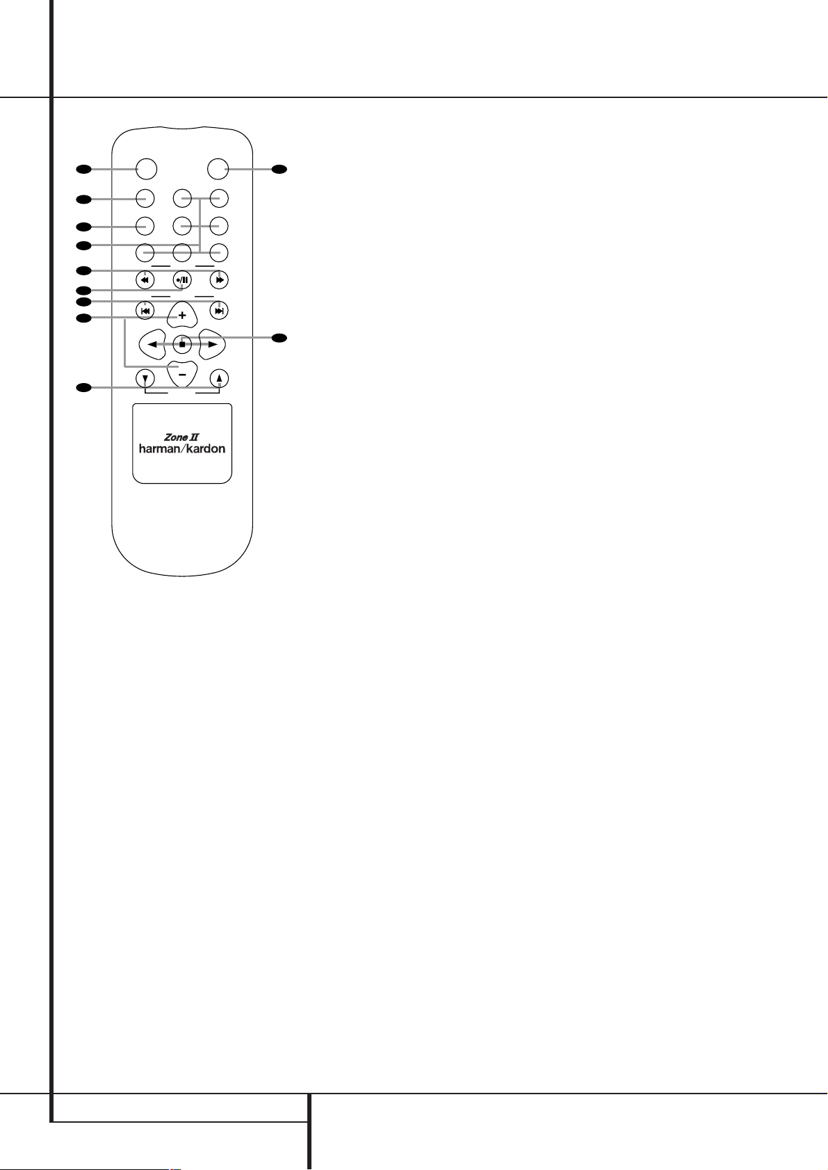
Zone II Remote Control Functions
å
Power Off
∫
AVR Selector
ç
AM/FM Tuner Select
∂
Input Selectors
≠
Tuning Up/Down – Fast Play
ƒ
Record/Pause
©
Preset/Track Skip
˙
Disc Skip
î
Volume Up/Down
∆
Play Forward/Reverse/Stop
K Mute
NOTE: The Zone II remote may be used in either
the same room where the AVR is located, or it
may be used in a separate room with an optional infrared sensor that is connected to the AVR’s
Multi IR input jack f. When it is used in the
same room as the AVR, it will control the functions of the AVR or any compatible Harman
Kardon products in that room. When it is used in
a separate room via a sensor connected to the
Multi IR Jack f, the buttons for power, input
source, volume and mute will control the source
and volume for the second zone, as connected
to the Multi Out Jacks •. (See page 42 for
complete information on using the Multiroom
system.)
The Zone II remote may be used in either the
same room where the AVR is located, or it may
be used in a separate room with an optional
infrared sensor that is connected to the AVR’s
Multi IR input jack
.
å
Power Off: When used in the room where
the AVR is located, press this button to place the
unit in Standby.When it is used in a remote
room with a sensor that is connected to the
Multi IR jack
, this button turns the Multi-
Room system off.
∫
AVR Selector: Press this button to turn on
the AVR. The input in use when the unit was last
on will be selected.
ç
AM/FM Tuner Select: Press this button to
select the Tuner as the input to the Multiroom
system. Press it again to change between the
AM and FM bands.
∂
Input Selectors: When the AVR is off,
press one of these buttons to turn the unit on
and to select a specific input. When the unit is
already in use, pressing one of these buttons will
change the input.
≠
Tuning Up/Down – Fast Play: These buttons may be used to change the frequency of
the tuner. These buttons may also control the
Fast Play or Fast Reverse functions of compatible
Harman Kardon CD, DVD or cassette decks in
the same room, or from a remote room when an
IR link is connected to the AVR.
ƒ
Record/Pause: Press this button to activate the Record or Pause function on compatible
Harman Kardon CD, DVD or Cassette Deck
products.
©
Preset Up/Down – Track Skip: When the
AVR’s tuner is selected as the input source, these
buttons will move up or down through the list of
stations that have been stored in the preset
memory.When a CD or DVD player is selected,
these buttons activate the forward or reverse
track or chapter skip functions.
˙
Disc Skip: Press this button to change
discs on compatible Harman Kardon CD or DVD
changers.
î
Volume Up/Down: When used in the
room where the AVR is located, press this button
to raise or lower the volume in that room. When
it is used in a remote room with a sensor that is
connected to the Multi IR Jack
, this button
will raise or lower the volume in the remote
room.
∆
Play Forward/Reverse/Stop: Press these
buttons to control compatible Harman Kardon
CD, DVD or cassette players.
K Mute:When used in the room where the
AVR is located, press this button to temporarily
silence the unit. When it is used in a remote
room with a sensor that is connected to the
Multi IR Jack O, this button will temporarily
silence the feed to the remote room only. Press
the button again to return to the previous volume level.
Important Note: No matter in which room the
Zone II remote is used, as with the main remote
it is important to remember to press the Input
Selector button
∂
that corresponds to the
unit you wish to operate befor you change the
device to be controlled.
/
POWER
A
B
C
D
E
F
G
H
I
AM/
OFF
AVR
FM
DVD
DN
DN
VID 1
VID 3
CD
TUNING
PRESET
DISC SKIP
DISC SKIP
VOLUME
MUTE
VID 2
VID 4
TAPE
UP
UP
K
J
INSTALLATION AND CONNECTIONS 15
After unpacking the unit, and placing it on a solid
surface capable of supporting its weight, you will
need to make the connections to your audio and
video equipment.
Audio Equipment Connections
We recommend that you use high-quality interconnect cables when making connections to
source equipment and recorders to preserve the
integrity of the signals.
When making connections to audio source
equipment or speakers it is always a good
practice to unplug the unit from the AC wall
outlet. This prevents any possibility of
accidentally sending audio or transient signals to
the speakers that may damage them.
1. Connect the analog output of a CD player to
the CD inputs
.
NOTE: When the CD player has both fixed and
variable audio outputs it is best to use the fixed
output unless you find that the input to the
receiver is so low that the sound is noisy, or so
high that the signal is distorted.
2. Connect the analog Play/Out jacks of a cassette deck, MD, CD-R or other audio recorder to
the Tape Input jacks
. Connect the analog
Record/In jacks on the recorder to the Tape
Output jacks
on the AVR.
3. Connect the digital output of any digital
sources such as a CD or DVD changer or player,
advanced video game, a digital satellite receiver,
HDTV tuner or digital cable set-top box or the
output of a compatible computer sound card to
the Optical and Coaxial Digital Inputs
*Ó
.
4. Connect the Coaxial or Optical Digital
Outputs
on the rear panel of the AVR to the
matching digital input connections on a CD-R or
MiniDisc recorder.
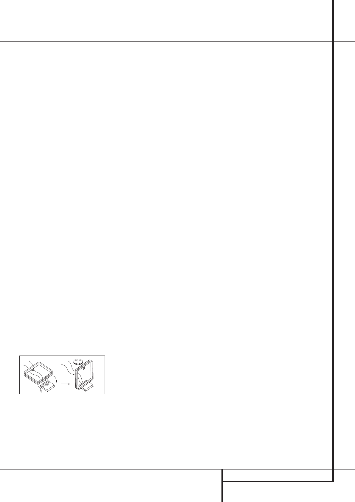
5. Assemble the AM Loop Antenna supplied with
the unit as shown below. Connect it to the AM
and GND screw terminals
.
6. Connect the supplied FM antenna to the FM
(75 ohm) connection
. The FM antenna may
be an external roof antenna, an inside powered
or wire lead antenna or a connection from a
cable system. Note that if the antenna or connection uses 300-ohm twin-lead cable, you should
use a 300-ohm-to-75-ohm adapter to make the
connection.
7. Connect the front, center and surround
speaker outputs
to the respective
speakers.
To assure that all the audio signals are carried to
your speakers without loss of clarity or resolution, we suggest that you use high-quality speaker
cable. Many brands of cable are available and
the choice of cable may be influenced by the distance between your speakers and the receiver,
the type of speakers you use, personal preferences and other factors.Your dealer or installer is
a valuable resource to consult in selecting the
proper cable.
Regardless of the brand of cable selected, we
recommend that you use a cable constructed of
fine, multistrand copper with an area greater than
2 mm
2
.
Cable with an area of 1.5 mm
2
may be used for
short runs of less than 4 m. We do not recommend that you use cables with an area less than
1mm
2
due to the power loss and degradation in
performance that will occur.
Cables that are run inside walls should have the
appropriate markings to indicate listing with any
appropriate testing agency standards. Questions
about running cables inside walls should be
referred to your installer or a licensed electrician
who is familiar with the applicable local building
codes in your area.
When connecting wires to the speakers, be certain to observe proper polarity. Note that the
positive (+) terminal of each speaker connection
now carries a specific color code as noted on
page 7. However, most speakers will still use a
red terminal for the postive (+) connection. Connect the “negative” or “black” wire to the same
terminal on both the receiver and the speaker.
NOTE: While most speaker manufacturers
adhere to an industry convention of using black
terminals for negative and red ones for positive,
some manufacturers may vary from this configuration. To assure proper phase and optimal performance, consult the identification plate on your
speaker or the speaker’s manual to verify polarity.
If you do not know the polarity of your speaker,
ask your dealer for advice before proceeding, or
consult the speaker’s manufacturer.
We also recommend that the length of cable
used to connect speaker pairs be identical. For
example, use the same length piece of cable to
connect the front-left and front-right or surround-left and surround-right speakers, even if
the speakers are a different distance from the
AVR.
8. Connections to a subwoofer are normally
made via a line level audio connection from the
Subwoofer Output
to the line-level input
of a subwoofer with a built-in amplifier. When a
passive subwoofer is used, the connection first
goes to a power amplifier, which will be connected to one or more subwoofer speakers. If you are
using a powered subwoofer that does not have
line-level input connections, follow the instructions furnished with the speaker for connection
information.
9. If an external multi-channel audio source with
5.1 or 7.1 outputs such as an external digital
processor/decoder, DVD-Audio or SACD player is
used, connect the outputs of that device to the
8-Channel Direct Inputs
.
Video Equipment Connections
Video equipment is connected in the same manner
as audio components.Again, the use of highquality interconnect cables is recommended to
preserve signal quality.
1. Connect a VCR’s audio and video Play/Out
jacks to the Video 1 or Video 2 In jacks
on the rear panel. The Audio and Video
Record/In jacks on the VCR should be connected
to the Video 1 or Video 2 Out jacks
on the AVR.
2. Connect the analog audio and video outputs
of a satellite receiver, cable TV converter or television set or any other video source to the Video
3
jacks.
3. Connect the analog audio and video outputs
of a DVD or laser disc player to the DVD jacks
.
4. Connect the digital audio outputs of a CD, MD
or DVD player, satellite receiver, cable box or
HDTV converter to the appropriate Optical or
Coaxial Digital Inputs
*Ó
.
NOTE: When connecting a device such as a digital cable box or other set-top tuner product with
a digital audio output, we recommend that you
connect both the digital and analog outputs of
the product to your AVR. The audio input polling
feature of the AVR will then be able to make certain that you have a constant audio feed, since it
will automatically switch the audio input to the
analog jacks if the digital feed is interrupted or
not available for a particular channel.
If your system requires direct connection of a
video source to your display, we suggest that you
consider programming the VDI Buttons
so
that you may change the input used by your display from the AVR’s remote. For information on
“learning” remote codes into a button on the
AVR remote, follow the instructions shown on
page 48.
5. Connect the Composite and S-Video (if
S-Video device is in use) Monitor Output
jacks on the receiver to the composite and
S-Video input of your television monitor or video
projector.
Installation and Connections

16 INSTALLATION AND CONNECTIONS
Installation and Connections
SCART A/V Connections
For the connections described above your video
device needs RCA (cinch) connectors or/and SVideo connectors for all Audio and Video signals:
Any normal video device (Not SVHS or High 8)
for only playback needs 3 RCA jacks,VCRs for
record and playback even 6 RCA jacks.Any
S-Video device (SVHS, High 8) needs 2 RCA
(Audio) and 1 S-Video jack (Video), if it´s a
playback unit, or 4 RCA (Audio In/Out) and
2 S-Video (Video In/Out) jacks, if it´s a recording
VCR.
Many european video devices are equipped with
RCA (Cinch) or S-Video jacks only partially, not
for all audio and video in/outputs needed as
described above, but with a so called Scart or
Euro-AV connector (almost rectangular jack with
21 pins, see drawings on next page).
In that case the following Scart to Cinch
adapters or cables are needed:
• Units for playback, such as satellite receivers,
camcorders, DVD or LD players, need an
adapter from Scart to 3 RCA plugs, see fig. 1
(normal video devices) or from Scart to 2
RCA+1 S-Video plugs, see fig. 4 (S-Video
devices).
• HiFi VCRs need an adapter from Scart to 6
RCA plugs, see fig. 2 (normal video), or from
Scart to 4 Audio+2S-Video jacks, see fig. 5
(S-Video VCR). Read carefully the instruction
attached to the adapter to find which of the
six plugs is used for the record signal to the
VCR (connect with the AVR´s Out jacks) and
for the playback signal from the VCR (connect
with the AVR´s In jacks). Do not misconnect
Audio and Video signals. Don´t hesitate to
consult your dealer, if you are uncertain.
• If you use only normal video devices the TV
monitor needs an adapter from 3 RCA plugs
to Scart (fig. 3) only. If also S-Video devices are
used an adapter from 2 RCA+1S-Video plugs
to Scart is needed additionally (fig. 6),
connected to the SCART input on your TV that
is provided for S-Video.
Note that only the video plugs (the "yellow"
cinch plug in fig. 3 and the S-Video plug in
fig. 6) must be connected to the TV Monitor
Output
, and the volume on the TV must be
reduced to minimum.
Important Note for Adapter Cables:
If the cinch connectors of the adapter you’ll use
are labeled, connect the Audio and Video ”In”
plugs with the corresponding Audio and Video
”In” jacks on the AVR (and with a VCR connect
the ”Out” plugs to the ”Out” jacks on the AVR).
Note that with some adapter types it may be
just turned around: If no signal is audible/ visible
when the VCR is playing connect the “Out”
plugs to the ”In” jacks on the AVR and turned
around. If the adapter plugs are not labeled in
that way, pay attention to the signal flow directions as shown in the diagrams above and in the
instruction attached to the adapter. If uncertain,
don’t hesitate to consult your dealer.
Important Notes for S-Video connections:
1. Only the S-Video In/Out of S-Video devices
must be connected to the AVR, NOT both,
normal video and S-Video In/Outputs (except the
TV, see item below).
When both connections are made, only the
S-Video signal will be viewed on the screen.
2. Like most common AV units the AVR does not
convert the Video signal to S-Video, only vice
versa. Thus both connections must be made from
the AVR to the TV if both, Video and S-Video
sources, are used, and the appropriate input on
the TV must be selected.
6. If your DVD Player has Y/Pr/Pb analog component video outputs, connect them to the
Component DVD Inputs
. Although this set
of inputs may be assigned to any of the four
video inputs on the AVR 635, the factory default
is for this input to be assigned to the DVD
Audio Inputs
Remember to make a digital
audio connection between the DVD player and
the AVR, with the Coaxial Digital Input 1
being the factory default. For information on
changing the input assignments for either the
component video jacks or the DVD player’s audio
connection, see page 20.
7. If you have other devices with Y/Pr/Pb or RGB
component video outputs, connect the source
device to the Component Video 1 and 2
Inputs
. The audio connections may be to
any of the Video Audio Inputs
Ô
or
the Optical or Coaxial Digital Inputs
*Ó
. When using either of the Component
Video Inputs, make certain that the audio and
video inputs are properly configured in the
IN/OUT SETUP menu, as described on
page 20.
8. If the component video inputs are used,
connect the Component Video Outputto
the component video inputs of your TV, projector
or display device.
9. If you have a camcorder, video game or other
audio/video device that is connected to the AVR
on a temporary, rather than permanent basis,
connect the audio, video and digital audio outputs of that device to the Front Panel Inputs
*ÓÔ
. A device connected to the Video 4
jacks
Ô
is selected as the Video 4 input, and
connected to the digital jacks
*Ó
it is selected
as "Optical 4" or "Coaxial 4" input. (See page
20 for more information on input configuration.)
Video Connection Notes:
• Y/Pr/Pb Component, RGB (see page 17), or
Composite video signals may only be viewed in
their native formats and will not be converted
to the other formats. S-Video signals will be
converted to composite signal. The OSD can be
viewed on the TV screen in any case, with Video
or S-Video input selected on the TV.
• When the component video jacks are used, the
on-screen menus will not be visible.You must
switch to the standard composite or S-Video
input on your TV to view those menus.
• All component inputs/outputs can be used for
RGB signals too, in the same way as described
for the Y/Pr/Pb signals, then connected to the
jacks with the corresponding color. But this is
only correct as long as only the three RGB
video signals are output by the video source,
with a sync signal in the "G" signal only, without any sync signal output separately by the
source.
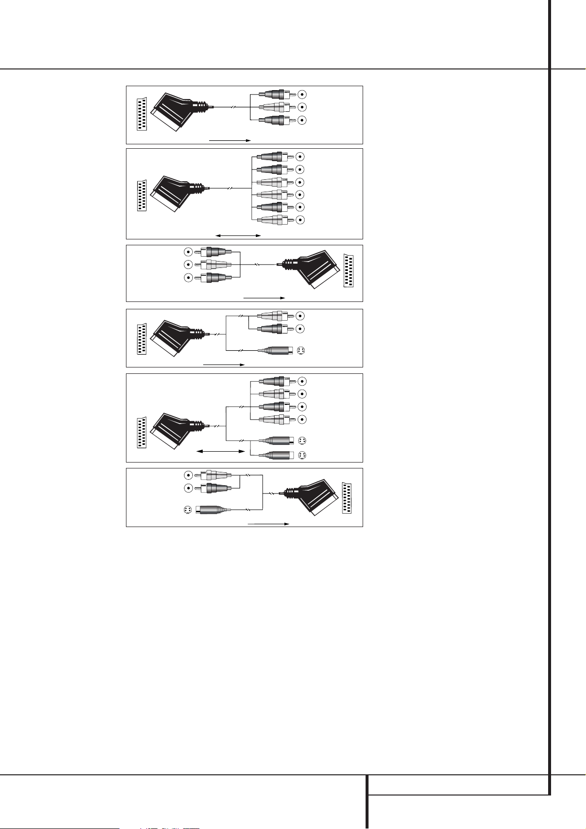
INSTALLATION AND CONNECTIONS 17
Installation and Connections
Black
Yellow
Red
Figure 1:
SCART/Cinch-Adapter for
playback;
signal flow:
SCART → Cinch
Black
Red
Blue
Yellow
Green
White
Figure 2:
SCART/Cinch-Adapter for
record and playback;
signal flow:
SCART ↔ Cinch
Black
Yellow
Red
Figure 3:
Cinch/SCART-Adapter for
playback;
signal flow:
Cinch → SCART
Rot
Schwarz
S-Video In
Figure 4:
SCART/S-Video Adapter
for playback;
signal flow:
SCART → Cinch
Schwarz
Rot
Blau
Gelb
S-Video In
S-Video Out
Figure 5:
SCART/S-Video Adapter
for record and playback;
signal flow:
SCART ↔ Cinch
Rot
Schwarz
S-Video Out
Figure 6:
SCART/S-Video Adapter
for playback;
signal flow:
Cinch → SCART
Black
Yellow
Red
Black
Red
Blue
1
Yellow
Green
1
White
Black
Yellow
Red
Red
Black
S-Video In
Red
Black
S-Video Out
Black
Red
Blue
1
Yellow
S-Video In
S-Video Out
1
Also other colours possible, e.g. brown and grey.
Important Note for the Use of
SCART-Cinch Adapters:
When video sources are connected to the TV
directly with a SCART cable, specific control
signals apart from Audio/Video signals will be
fed to the TV. These specific signals are: With all
video sources, the signal for automatic input
selection that switches the TV automatically to
the appropriate input as soon as the video
source is started. And with DVD players, the
signals automatically turning the TV to 4:3/16:9
format (with 16:9 TVs or with 4:3 TVs with
selectable 16:9 format) and turning the RGB
video decoder of the TV on or off, depending on
the DVD player´s setting. With any adapter cable,
these control signals will be lost and the
appropriate setting of the TV must be made
manually.
Note for RGB signal with SCART:
If you use a unit providing RGB signals on a
SCART output (as e.g. most DVD players do) and
you want to use that RGB signal, this SCART
output must be connected directly to your TV.
Although the AVR can switch three-way video
signals (like component signals Y/Pb/Pr), most
TVs need separate sync signals for RGB (also
with SCART) that cannot be switched and provided by the AVR.
RGB signals can be pathed through the AVR only
when no separate sync signal is needed (see last
”Video Connection Note” on page 16).

18 INSTALLATION AND CONNECTIONS
System and Power Connections
The AVR 635 is designed for flexible use with
multiroom systems, external control components
and power amplifiers.
Main Room Remote Control Extension
If the receiver is placed behind a solid or smoked
glass cabinet door, the obstruction may prevent
the remote sensor from receiving commands. In
this event, the remote sensor of any Harman
Kardon or other compatible device, not covered
by the door, or an optional remote sensor may
be used. Connect the Remote IR Output of
that device or the output of the remote sensor to
the Remote IR Input jack
.
If other components are also prevented from
receiving remote commands, only one sensor is
needed. Simply use this unit’s sensor or a remote
eye by running a connection from the Remote
IR Output jack
to the Remote IR Input
jack on Harman Kardon or other compatible
equipment.
Multiroom IR Link
The key to remote room operation is to link the
remote room to the AVR’s location with wire for
an infrared receiver and speakers or an amplifier.
The remote room IR receiver (this can be an
optional IR receiver or any other remotable
Harman Kardon device in the remote room with
IR sensor integrated) should be connected to the
AVR via standard coaxial cable. Connect the
Remote IR Output of the device or of the
optional sensor with the Multiroom IR Input
jack
on the AVR’s rear panel.
If other Harman Kardon compatible source
equipment is part of the main room installation,
the Remote IR Output jack
on the rear
panel should be connected to the IR IN jack on
that source device.This will enable the remote
room location to control source equipment
functions.
When a remote IR sensor is used to control nonHarman Kardon source equipment, we recommend that you make a direct connection or use
an optional, external IR “blaster” connected to
the Remote IR Carrier Output Jack
. If you
are in doubt as to which IR Output jack to use
for the equipment in your system, contact your
dealer or installer, or the manufacturer’s support
site and ask whether the unit to be controlled
uses “full carrier” or “stripped” carrier IR commands.When “full carrier commands” are used,
make the connection to the Remote IR Carrier
Output Jack
. Otherwise, make the connec-
tion to the Remote IR Output Jack
as
noted above.
NOTE: All remotely controlled components must
be linked together in a “daisy chain”. Connect
the IR OUT jack of one unit to the IR IN of the
next to establish this chain.
Multiroom Audio Connections
Depending on your system`s requirement and
distance from the AVR to the remote room, three
options are available for audio connection:
Option 1: Use high-quality, shielded audio
interconnect phono cable from the AVR’s location to the remote room. In the remote room,
connect the interconnect cable to a stereo
power amplifier. The amplifier will be connected
to the room’s speakers. At the AVR, plug the
audio interconnect cables into the Multiroom
Output Jacks
on the AVR’s rear panel.
Option 2: Place the amplifier that will provide
power to the remote location speakers in the
same room as the AVR, and connect the
Multiroom Output jacks
on the rear panel
of the AVR to the audio input of the remote
room amplifier. Use the appropriate speaker wire
to connect the optional power amplifier to the
remote speakers. High-quality wire of at least
2.5 mm
2
is recommended for long multiroom
connections.
Option 3: Taking advantage of the AVR’s builtin seven-channel amplifier, it is possible to use
two of the amplifier channels to power speakers
in the remote room. When using this option you
will not be able to use the full 7.1-channel
capabilities of the AVR in the main listening
room, but you will be able to add another
listening room without additional external
power amplifiers.To use the internal amplifiers
to power a remote zone, connect the speakers
for the remote room location to the Surround
Back/Multiroom Speaker Outputs
.
Before using the remote room you will need to
configure the amplifiers for surround operation
by changing a setting in the Multiroom menu,
following the instructions shown on page 42.
NOTE: For all options, you may connect an
optional IR sensor (Harman Kardon He 1000) in
the remote room to the AVR via an appropriate
cable. Connect the sensor’s cable to the
Multiroom IR Input
on the AVR and use
the Zone II remote to control the room volume.
Alternatively, you may install an optional volume
control between the output of the amplifiers and
the speakers.
A-BUS Installation Connections
The AVR is among the very few receivers
available today that offers built-in A-BUS Ready
®
operation. When used with an optional A-BUS
keypad or control module, you have all the
benefits of remote zone operation without the
need for an external power amplifier.
To use the AVR with an approved A-BUS
product, simply connect the keypad or module
that is in the remote room to the AVR using
standard “Category 5” wiring that is properly
rated for the inwall use specific to the installation. Terminate the wiring at the receiver end to
a standard RJ-45 jack in compliance with the
instructions furnished with the A-BUS module.
No further installation or adjustment is needed,
as the A-BUS connector on the AVR routes the
signals in and out of the keypad to their proper
destination for power, signal source and control.
The output fed to the A-BUS jack is determined
by the AVR’s multiroom system, and the menus
may be used as is.
RS-232 Connections
The AVR is equipped with an RS-232 Serial
Connection Port
that may be used for two
purposes.When the port is connected to a compatible, optional, external computer, keypad or
control system the AVR is capable of bi-directional communications that enable the external
system to control the AVR, and for the AVR to
report status and handshake data back to the
controller. Use of the RS-232 port for this type of
control requires specific technical knowledge,
and we recommend that any connection and
programming for control be made by a trained
installer or technician familiar with the equipment being used. The RS-232 port may also be
used as an access point through which the AVR’s
operating system and surround mode memories
may be updated via connection to a compatible
computer. At the time that any upgrade is available, instructions for making the connection and
installing the upgrade will be available through
the Product Support area of the Harman Kardon
Web site at www.harmankardon.com.
The physical connection to the AVR’s RS-232
port is a standard D-9 connection but to assure
compatible and proper operation, specific software commands and pin wiring schemes may be
required.
AC Power Connections
This unit is equipped with two accessory AC
outlets.They may be used to power accessory
devices, but they should not be used with
high-current draw equipment such as power
amplifiers.The total power draw to the
Unswitched Outlet
must not exceed
100 watts, that to the Switched Outlet
50 watts.
The Switched
outlet will receive power only
when the unit is on completely.This is recommended for devices that have no power switch
or a mechanical power switch that may be left in
the “ON” position.
NOTE: Many audio and video products go into a
Standby mode when they are used with
switched outlets, and cannot be fully turned on
using the outlet alone without a remote control
command.
The Unswitched
outlet will receive power
as long as the unit is plugged into a powered AC
outlet and the Main Power Switch
1
is on.
Installation and Connections
 Loading...