

Page 1

CU-
MANUAL SPRAY GUN
OPERATING INSTRUCTIONS & REPLACEMENT PARTS
INSTRUCTIONS & PARTS LIST CU-8/31/2011
Supersedes Instructions & Parts List CU-6/2008
WARNING: Spray materials may be harmful if inhaled or
allowed to come into contact with the skin or eyes. Consult
the product label and Material Safety Data Sheet supplied
for the spray material. Follow all safety precautions.
CAUTION: Well Vent ilat ed Area Requ ired t o rem o ve
fume s , dust o r overspray. S e c ure ai r h o s e and f l u i d
hose wrench tight for safety and to prevent leaks.
M a x i m u m A i r P r e s s u r e 1 0 0 P . S . I .
M a x i m u m F l u i d P r e s s u r e 4 5 P. S . I .
DESCRIPTION:
CU- Manual Spray Guns are for use from Low to Medium Pressure
with Light to Heavy Fluids. They will cover a range of materials to
include heavy Abrasives, Enamels, Latex, and Lacquers etc. See
page 2 for different styles of Srpay Head Components and page 4
for information on available Fluid Bodies. These Models require 3
to 24 C.F.M. at 30 to 50 lbs. Air Pressure depending on Spray
Head selected and Material being sprayed.
CONNECTIONS:
Spray Guns have the following threaded connections: Air inlet
1/4" N.P.T. (Male) and Fluid inlet 3/8" N.P.T. (Male).
MATERIAL:
Mixture should be to the consistency recommended by the
manufacturer. Strain through cloth or fine mesh wire prior to
using material. This will insure that all foreign particles are
removed.
OPERATION:
1. Blow out all airline hoses before connecting to the
Spray Gun to remove foreign particles.
2. Connect HT-1/4 or 5/16 Air Hose to air inlet fitting.
3. Connect HA-1/4 or 3/8 Fluid Hose to fluid inlet.
4. Tighten all hose connections securely.
5. Adjust air pressure to required amount at the
Regulator & Moisture Condenser Unit.
6. Adjust fluid volume on the CUF- Model by turning the
200-17 Fluid Knob.
7. The Fan pattern is controlled by turning the U-2065
Fan Control Screw on the CUF- Model.
8. Test spray on some cardboard or news paper for final
adjustment before spraying your project.
MAINTENANCE:
The specially treated leather packings (U-28) should be replaced
at least once a month. Old U-28 Packing Washers can cause
leakage of air and fluid. PTFE Packings (59-28 Packing
Assembly) are self-lubricating.
TROUBLE SHOOTING SPRAY PATTERNS:
A. A ROUGH OR STIPPLE FINISH is due to low or restricted
flow of air pressure or heavy materials being applied with the
spray gun too close to surface.
B. A WET OR SAGGING FINISH is due to low air pressure or
restricted flow of air, material being too thin or applied too
close to the surface.
C. A SPUTTERING SPRAY is caused by air leaking into fluid
line or can be caused by a loose fluid tip, a broken or split tip,
lumpy material, a clogged vent hole in cover of material cup,
air leak at fluid pipe attached to inside of tank cover, or a
clogged paint strainer.
TO CORRECT: Tighten tip securely or replace. Strain
material and clean strainer. Sputtering might also be caused
by worn packing washers, or worn or scored needle.
D. AN ARCHED FAN SPRAY PATTERN is caused by dried
material accumulated in one fan port of the fan aircap,
distorting the pattern.
TO CORRECT: Dissolve material inside fan port with
suitable water/solvent applied with a small brush.
Never use wire or sharp instruments to clean fan ports
as permanent damage to the air ports will result in
altering uniformity of the fan spray pattern.
E. UNBALANCED FAN SPRAY PATTERN, heavy on one side,
may be caused by material collecting around outside of the
fluid tip and aircap, or by a loose aircap.
TO CORRECT: Remove aircap and clean fluid tip and aircap
with water/solvent, dry with air pressure. Always be sure fan
aircap and aircap body is tightened securely.
F. A HEAVY CENTER in a fan pattern is caused by insufficient
air pressure at the fan port. Rough or shady edges are also
caused by low air pressure.
TO CORRECT: Increase air line pressure.
G A SPLIT FAN SPRAY PATTERN, heavy on each end and
light in the center, is caused by excessive air pressure.
TO CORRECT: Reduce air pressure.
CLEANING:
After each use flush clean solvent through the fluid passages of the
Spray Gun and wipe off the outside with clean solvent. Never leave
the entire Spray Gun immersed in solvent. Dirty Aircaps and Tips
should be cleaned by soaking in solvent and then blown clean with
air. Personal Safety Equipment should be used at all times.
Paasche Airbrush Company
4311 North Normandy Avenue
Chicago, IL 60634-1395
Phone: 773-867-9191 • Fax: 773-867-9198
Website: paascheairbrush.com
E-Mail: info@paascheairbrush.com
Printed in the U.S.A.
Page 2
SPRAY HEAD COMPONENTS
Page 2
Spr ay Heads for CU- Manual Spray Gu ns are availa ble in severa l different styles, some of whic h are
avail able with Stain less Steel components. The C.F.M. requirements range from 3 to 24 C. F.M. @ 40 to 50
lbs. air pres sure. NOTE: Whe n eith er flu id Tip or fluid Needle is worn and requires replacemen t, it is
recom mended that both items be changed for best res ults. All Tips and Need les are made using 303
Stainless Steel. Carbide Tips & N eedles are a vailable fo r use with abrasive m aterials.
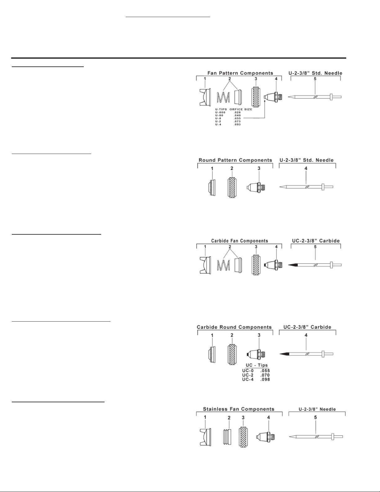
EXTERNAL- FAN PATTERN
• Application: Broad coverage - High Production.
• Sizes: 000-3, 00-4, 00-4-6, 06, 0-9, 2-8, 4-10, 4-15.
• Fluid Viscosity: Light to Heavy (3 to 24 C.F.M.@ 40 or 50 P.S.I.)
1. 56FA- Aircap Body (Select Size above)
2. U-2639S Sleeve & Spring
4. U-1649 Aircap Nut
5. U- Stainless Tip (Select Size 000,00,0,2,4)
6. U-2-3/8 Stainless Needle
INTERNAL- ROUND PATTERN
• Application: Narrow trim, inside crevice, dot, line, High Production.
• Sizes: 2-5, 4-6.
• Fluid Viscosity: Light to Medium (3 to 6 C.F.M. @ 40 P.S.I.)
1. 56RA- Aircap Body (Select Size above)
2. U-1649 Aircap Nut
3. U- Stainless Tip (Select Size 2 or 4)
4. U-2-3/8 Stainless Needle
CARBIDE INSERT- FAN PATTERN
• Application: Abrasive Materials
• Sizes: 0-9, 2-8 or 4-10
• Fluid Viscosity: Light to Medium (4 to 12 C.F.M. @40 or 50 P.S.I.)
1. 56CFA- Aircap Body (Select Size above)
2. U-2639S Sleeve & Spring
3. U-1649 Aircap Nut
4. UC- Carbide Insert Stainless Body Tip (Select Size 0, 2 or 4)
5. UC-2-3/8 Carbide Insert Stainless Needle
CARBIDE INSERT- ROUND PATTERN
• Application: Abrasive Materials
• Sizes: 2-5 & 4-6
• Fluid Viscosity: Light to Medium (3 to 6 C.F.M. @ 40 P.S.I.)
1. 56CRA- Aircap Body (Select Size above)
2. U-1649 Aircap Nut
3. UC- Carbide Insert Stainless Body Tip (Select Size 2 or 4)
4. UC-2-3/8 Carbide Insert Stainless Needle
StainleSS Steel
• Application: Corrosive materials and Latex.
• Sizes: 0-6, 0-9, 2-8, 4-10, 4-20-3.
• Fluid Viscosity: Light to Medium Heavy (4 to 20 C.F.M. @ 40 or 50 P.S.I.)
1. 56SFA- Stainless Aircap Body (Select Size above)
2. U-2639P Poly Sleeve
3. U-1649 Aircap Nut (plated brass)
4. U- Stainless Tip (Select Size 0, 2 or 4)
5. U-2-3/8 Stainless Needle
- FAN PATTERN
Page 3

CU- Spray Gun
CU- Spray Gun Components
No.Part No. Description
1. U-2-3/8 Needle
2. CU-7B Fluid Body
Page 3
U-2072 FAN CONTROL ASSEMBLY
4. AE-43 “O” Ring
5. U-2065 Fan Control Screw
U-3500 PACKING ASSEMBLY
8. U-28-12 Packing Washers (1 Doz.)
9. U-29 Packing Gland (1)
10. DU-30 Spring (1)
11. U-31 Spring Seat (1)
12. U-33 Spring (1)
U-1858-1/4 HANDLE & SHELL ASSEMBLY
13. U-2153 Retaining Ring
14. U-58Nut
15. U-755 Link Sleeve
16. U-828 Hook
17. U-856 Screw
18. U-2154A Shell Assembly
19. U-762 Air Valve Piston
20. U-2520P Air Valve Head
21. U-2500 Spring
U-2106B FLUID CONTROL ASSEMBLY
22. U-2631 Plunger
23. U-2750 Packing Gland
24. AE-43 “O” Ring
25. U-2069B Rear Cap
26. 200-17 Fluid Knob
27. U-1702 Valve Spring
No. Part No. Description
59-28 PTFE PACKING ASSEMBLY
32. U-3353 Packing (PTFE)
33. 59-24 Packing (PTFE) (2)
34. 59-25B Expander Gland
35. DU-30 Spring
OPTIONAL TIPS & NEEDLES
1. URE-00, 0, 2 or 4 Tip (Select Size)
2. URE-1-17/32 Needle
Rear needle seat for Heavy Pigments that would collect
and clog in the cavity of the standard tip.
3. US-0, 2 or 4 Self Cleaning Tip (Select)
(US-0 same as U-0)
4. US-0-2-3/8 Self Cleaning Needle
US-2-2-3/8
US-4-2-3/8
Use to prevent buildup at tip orifice & pressure feed.
28. U-1322A Link Sleeve
29. U-35 Trigger Link Screw
30. U-1671 Trigger
31. U-1890P Durable Plastic Handle
32. U-807 Air Inlet Tube Assembly
Page 4

CU- Spray Gun & Extensions
CAM-LOCK & SCREW COVER CUP ASSEMBLIES
30SC QT. CUP ASSEM.
CL-38 QT. CAM-LOCK &
34SC 1/2 PT. CUP ASSEM.
Page 4
52P QT. CUP ASSEM.
Gun Not Included
CU- FLUID BODIES (See picture below)
1. CU-7B Forged Brass
CUS-7B Stainless Steel
2. CUA-7B Separate Air Atomizing Inlet - Brass
CUSA-7B Separate Air Atomizing Inlet - Stainless St.
3. CUG-7B Circulating Fluid Body - Brass
NOTE: U-28-12 and DU-28-12 Packing Washers only sold by the dozen.
 Loading...