

Page 1

BUB- (Bottom Air Inlet)
BUT- (Thumb Action Trigger)
MANUAL SPRAY GUNS
OPERATING INSTRUCTIONS & REPLACEMENT PARTS
INSTRUCTION AND PARTS LIST BUB & BUT-8/31/2011
Supersedes Instruction & Parts list BU & BUT-6/2008
WARNING: Spray materials may be harmful if inhaled or
allowed to come into contact with the skin or eyes. Consult
the product label and Material Safety Data Sheet supplied
for the spray material. Follow all safety precautions.
CAUTION: W ell Venti l ated Area Req u ired to rem o ve
fumes, dust o r o versp r a y. S e c u r e a i r h o s e a n d flu i d
hose w r e n c h t i g h t f o r sa f e t y a n d to prev e n t le a k s .
M a x i m u m A i r P r e s s u r e 1 0 0 P . S . I .
M a x i m u m F l u i d P r e s s u r e 4 5 P. S . I .
DESCRIPTION:
BUB- and BUT- Manual Spray Guns (“T” means thumb
action) are for use with Light to Medium consistency
materials. These models require 2 to 14 C.F.M. @ 30 to
40 P.S.I. air pressure depending on size of Multiplehead
selected.
AIR CONNECTIONS:
These models have 1/4'' N.P.T. Air Inlet.
1. Open air control valve and blow out Air Hose to
remove any foreign particles that may be in airline.
Secure air hose so it doesn’t injure anyone during
purging.
2. Connect air hose to the U-807 Air Inlet Tube on
BUB- Bottom Air Inlet Model. Connect air hose to
U-49A Valve Casing on BUT- Thumb Action Spray
Gun.
FLUID CONNECTIONS:
These models have 3/8'' N.P.T. Fluid Inlet.
1. For Siphon Feed, attach siphon feed cup to bottom
inlet of Fluid Body Assembly.
2. For Gravity Feed, loosen U-58 Nut and then turn
fluid inlet of Fluid Body Assembly to top of Spray
Gun and connect Gravity Feed Cup. Tighten U-58
Nut.
3. Pressure Tank operation requires that you attach
one end of fluid hose to pressure tank and the
other end to the fluid inlet on the Fluid Body
Assembly.
MATERIAL:
1. Mixture should be to the consistency
recommended by the manufacturer.
2. Strain all materials through a cloth or fine wire
mesh prior to using to insure all foreign particles
have been removed.
OPERATION:
1. Adjust 200-17 Fluid Knob on BUB- (Bottom air
inlet) Model to regulate the flow of material through
the Spray Gun.
2. To control fluid on the BUT- Spray Gun, adjust the
U-1816 Adjusting Screw on the trigger.
Grip Spray Gun as you would a pistol, place two fingers on
the trigger. The first one quarter inch pull releases air only
and is used for cleaning by dusting surfaces before
painting. Continued pull on the trigger retracts the Fluid
Needle and allows maximum fluid passage.
Begin Painting by applying as light a coat as possible. Take
long strokes from side to side releasing the trigger at the end
of each stroke. For average work, hold head of Spray Gun
6 to 8 inches from the surface; for narrow lines, use short
trigger pull and hold Spray Gun closer to the surface. To get
wider spray patterns, draw Spray Gun away from surface
gradually while trigger is pulled back until desired width of
pattern is obtained. Practice before spraying on your project
is always advisable.
CARE AND CLEANING:
Flush clean solvent through the fluid passages of the Spray
Gun and wipe off the outside. Never leave the entire Spray
Gun immersed in solvent or the leather packings will dry out.
Dirty Aircaps and Tips should be cleaned out by soaking in
solvent and then blown clean with air. Never use wire
objects to ream out the holes in aircaps or tips as this will
damage these items. Always follow safety instructions on
cleaning solvents being used and remember to keep your
containers closed in a safe location.
Paasche Airbrush Company
4311 North Normandy Avenue
Chicago, IL 60634-1395
Phone: 773-867-9191 • Fax: 773-867-9198
Website: paascheairbrush.com
E-Mail: info@paascheairbrush.com
Printed in the U.S.A.
Page 2
BUB- Manual Spray Guns
Page 2
BUT- Thumb Action Spray Gun
Page 3

BUB & BUT PARTS LIST & ACCESSORIES
Page 3
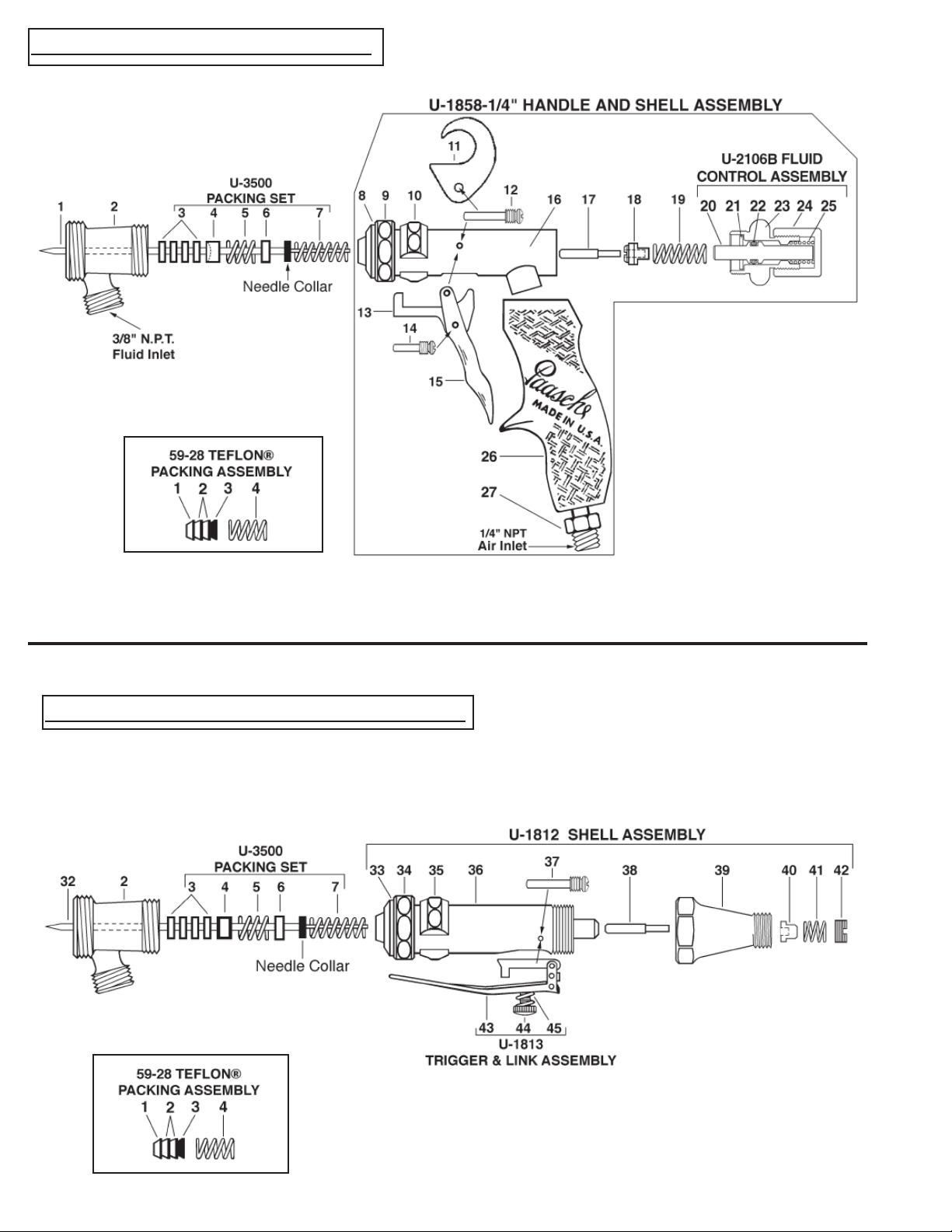
1. U-2-3/8 Needle
2. BU-7B Standard Fluid Body
U-3500 Packing Set (Same on all Models)
3. U-28-12 Packing Washers (4)
4. U-29 Packing Gland
5. DU-30 Spring *
6. U-31 Spring Seat
7. U-33 Spring *
Model BUB
1. U-2-3/8 Needle
Note: Not included with U-1858-1/4
U-1858-1/4 Handle & Shell Assembly
8. U-2153 Retaining Ring
9. U-58 Nut
10. U-755 Link Sleeve
11. U-828 Hook
12. U-856 Trigger & Hook Screw *
13. U-1322A Link Assembly *
14. U-35 Trigger Link Screw *
15. U-1671 Trigger *
16. U-2154A Shell Assembly
17. U-762 Air Valve Piston *
18. U-2520P Air Valve Head
19. U-2500 Spring *
59-28 PTFE Packing Assembly (Optional)
1. U-3353 Packing Teflon ® (1)
2. 59-24 Packing Teflon ® (2)
3. 59-25B Packing Expander (1)
4. DU-30 St. St. Spring (1) *
CONTAINERS:
• 47SCJ, 31SC, 35SC, 30SC, 34SC, other sizes
available call for bulletin C & B.
* Denotes Stainless Steel
U-2106B Fluid Control Assembly (Air Inlet In Handle)
20. U-3631 Plunger
21. U-2750 Packing Gland
22. AE-43 “O” Ring
23. U-2069B Rear Cap
24. 200-17 Fluid Knob
25. U-1702 Valve Spring
26. U-1890P Plastic Handle
27. U-807 Air Inlet Tube for BUB- MODEL
Model BUT
32. BUT-2-1/2 Needle
Note: Not Included with U-1812
U-1812 Shell Assembly
33. U-2153 Retaining Ring
34. U-58 Nut
35. U-755 Link Sleeve
36. U-1811 Shell
37. U-40 Trigger Screw *
38. U-194 Air Valve Piston *
39. U-49A Valve Casing
40. U-154P Air Valve Head
41. U-1853 Air Valve Spring *
42. U-48 Strainer Nut
U-1813
Trigger & Link Assembly
43. U-193A Trigger & Link
44. U-1816 Adjusting Screw
45. U-1815 Trigger Stop Spring *
Page 4

SPRAY HEAD COMPONENTS
Spray Heads for BUB & BUT- Manual Spray Guns are available in several different Styles, some of which are available with
Stainless Steel components. The C.F.M. requirements range from 2 to 14 C.F.M. @ 30 to 50 lbs. air pressure. NOTE: When
either fluid Tip or fluid Needle is worn and requires replacement, it is recommended that both items be changed for best results.
All Tips and Needles are made using 303 Stainless Steel. Carbide Tips and Needles are available for use with abrasive materials.
Page 4
HVLP - HIGH VOLUME LOW PRESSURE - FAN PATTERN
when used with part No. U3609 Air Inlet Tube at maximum
50 P.S.I. Air Pressure.
• Sizes: 0 or 2
1.BFHA- Fan Aircap (Select Size)
2.BU-12 Aircap Nut
3.U- Stainless Tip (Select Size)
4.U-2-3/8 Stainless Needle
EXTERNAL- FAN PATTERN
• Sizes: 2, or 4
• Application: Hand application in tight areas.
• Fluid Viscosity: Light to Medium (2 to 6 C.F.M. @ 30 P.S.I.)
1.BNFA- Fan Aircap (Select Size)
2.BU-12 Aircap Nut
3.U- Stainless Tip (Select Size)
4.U-2-3/8 Stainless Needle for BUB- Model
BUT-2-1/2 Stainless Needle for BUT- Model
INTERNAL- ROUND PATTERN
• Sizes: 2 or 4
• Application: Fine lines, detailing stenciling and touch-up.
• Fluid Viscosity: Light to medium (2 to 3.5 C.F.M. @ 40 P.S.I.)
1.BR-15- Aircap Body (Select Size)
2.BU-12 Aircap Nut
3.U- Stainless Tip (Select Size)
4.U-2-3/8 Stainless Needle for BUB- Model
BUT-2-1/2 Stainless Needle for BUT- Model
STAINLESS- INTERNAL- ROUND PATTERN
• Size: 4
• Application: BSR- Latex, silver nitrate, acidic materials.
• Fluid Viscosity: Light to medium (2 to 3.5 C.F.M. @ 40 P.S.I.)
1.BSR-15- Stainless Aircap Body
2.U- Stainless Tip (Select Size)
3.BUS-12 Stainless Aircap Nut
4.U-2-3/8 Stainless Needle for BUB- Model
BUT-2-1/2 Stainless Needle for BUT- Model
STAINLESS- EXTERNAL- FAN PATTERN
• Sizes: 0 only
• Application: Broad coverage of Latex and Corrosive materials.
• Fluid Viscosity: Light to Medium (3 to 5 C.F.M. @ 40 P.S.I.)
1.BSF-15- Stainless St. Fan Aircap (Select Size)
2.BUS-12 Stainless Aircap Nut
3.U- Stainless Tip (Select Size)
4.U-2-3/8 Stainless Needle for BUB- Model
BUT-2-1/2 Stainless Needle for BUT- Model
Special Tips & Needles
• US-0, 2 or 4 Self Cleaning Tip (Select Size)
(US-0 same as U-0)
US-0-2-3/8 Self Cleaning Needle (Match Tip Size)
US-2-2-3/8
US-4-2-3/8
 Loading...