

Page 1

BUS2RS and BUS2FS
DUAL FLUID SPRAY GUNS
OPERATING INSTRUCTIONS AND REPLACEMENT PARTS
INSTRUCTIONS AND PARTS LIST, SILVER-8/31/2011
Supersedes Instructions & Parts list, SILVER-11/04/2008
WARNING: Spray materials may be harmful if inhaled or allowed
to come into contact with skin or eyes. Consult the product label
and Material Safety Data Sheet supplied for the spray material.
Follow all safety precautions. CAUTION: Well Ventilated
Area Required to remove fumes, dust or overspray.
Check compatibility of materi als used with Polyethylene
container and PVC Fluid Hose. Secure airhose and fluid
hose wrench tight for safety and to prevent lea ks.
M a x i m u m A i r P r e s s u r e 6 0 P . S . I .
M a x i m u m F l u i d P r e s s u r e 4 5 P . S . I .
INTRODUCTION:
These Manual Spray Guns require clean dry air pressure
regulated to provide from 6 to 8 C.F.M. at 40 to 60 lbs. air
pressure depending on size and number of atomizing
heads to be used. Paasche Regulator & Condenser
Units are recommended for attaching to air supply line to
remove water, oil, rust or scale and help insure quality
finish of coating. They have no parts that require
replacement and clean themselves each time the drain
valve is opened to remove accumulation of filtered
contaminates.
AIR AND FLUID CONNECTIONS:
1. Air Connection: To remove any accumulated
foreign matter blow out all hoses before using.
a. Air supply to Spray Gun must be turned off
before attaching fittings to the Air Inlet.
b. Attach HT-1/4 Air Hose to the Air Outlet on the
Air Regulator and Air Inlet on the bottom of
the handle on the Spray Gun.
2. Fluid Hose Connection: HPT-1/4 PVC Fluid Hose
with HPTSC-Stainless Steel Couplings should be
long enough to form a loop below the Spray Gun at
all times when using fluid hose to feed material to
the Spray Gun (two required).
a. Attach HPTSC-1/4 St. St. Couplings to the
fluid inlets of the two Fluid Bodies.
b. Attach opposite ends, HPTSC-1/4-3/8 St. St.
Couplings, to containers of respective
materials being sprayed.
3. Fluid Container Connection: When using USP-QT
(QT./.946 l) Plastic Bottle Assemblies, make sure
Screw Covers are tightened securely so fluid will
not leak at Bottle connections.
4. Tighten all Air and Fluid connections securely.
OPERATION:
1. After hose connections have been made, regulate
the air pressure to about 40 lbs. atomizing pressure
and then pull trigger back slowly.
a. The first 1/4" of trigger stroke opens the Air
Valve which operates the cylinder action of
the right side atomizing components.
b. Continued pull on the trigger opens both of
the atomizing Spray Heads for spraying.
2. The U-1460 Adjusting Nut (part 39) can be used to
regulate desired amount of fluid to the automatic
Spray Head and the 200-17 Fluid Knob (part 27)
can be used to adjust fluid to the manual side of the
two headed spray gun.
3. Dual Fluid Spray Guns are designed to atomize and
mix fluid materials outside the atomizing aircaps.
This prevents materials from hardening inside the
spray gun.
4. The U-28-12 Packing Washers (part 6) should be
replaced periodically.
a. Fill packing cavity with 3 new U-28-12
Packing Washers and replace U-29 Packing
Gland (part 7), DU-30 Spring (part 8) and U31 Spring Seat (part 9) in position.
b. A few drops of oil should occasionally be
applied to the U-2506 Piston Leather (part Z)
to keep it pliable.
Paasche Airbrush Company
4311 North Normandy Avenue
Chicago, IL 60634-1395
Phone: 773-867-9191 • Fax: 773-867-9198
Website: paascheairbrush.com
E-Mail: info@paascheairbrush.com
Printed in the U.S.A.
Page 2
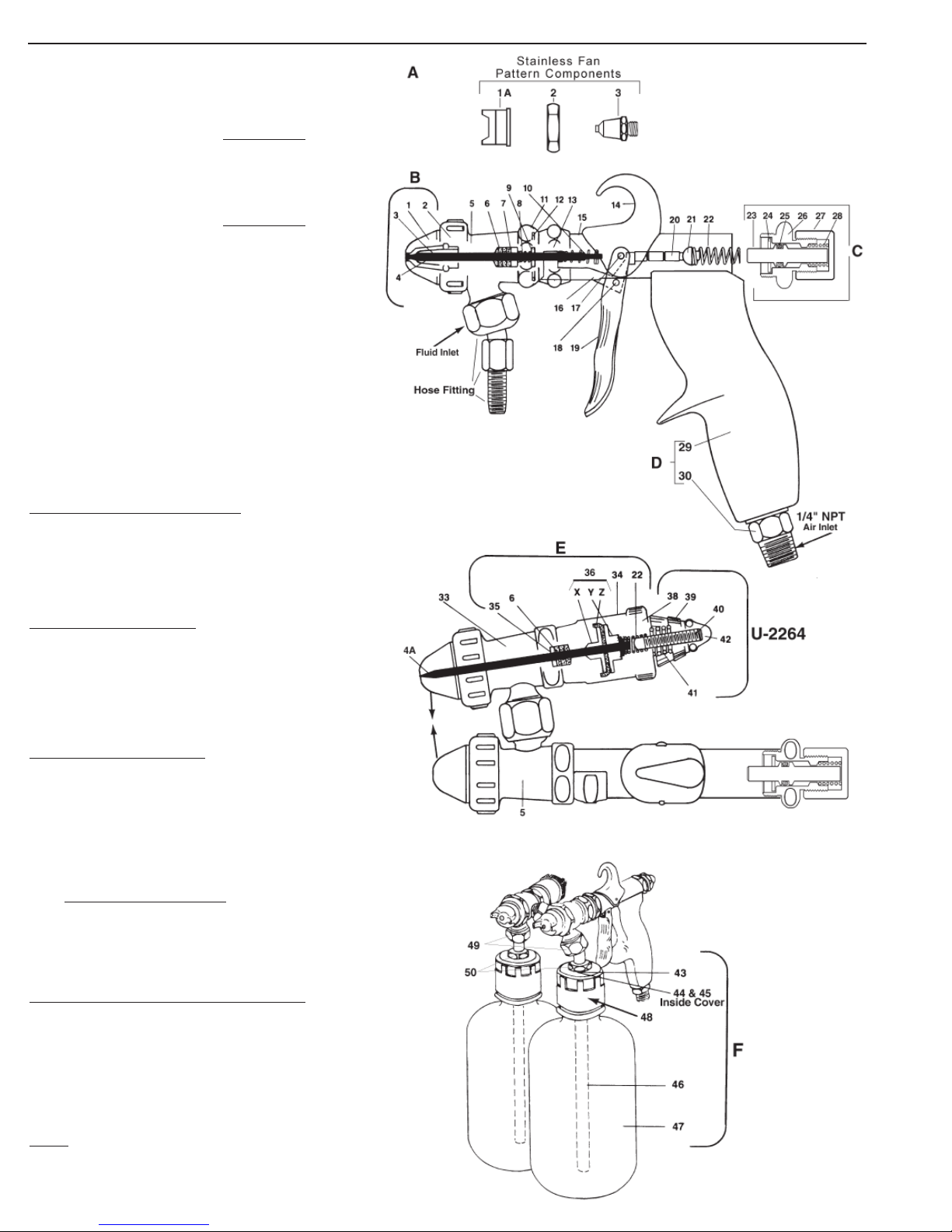
1A. BSF-15-0 Stainless Fan Aircap
2. BUS-12 Stainless Aircap Nut
3. U-0 Stainless Tip
4. U-2-3/8 Stainless Needle
4A. A-U-3-1/32 Stainless Needle
(Fig. E Cylinder Action)
1. BSR-15-2 or 4 Stainless Aircap(Select Size)
2. BUS-12 Stainless Aircap Nut
3. U-2 or 4 Stainless Tip (Select Size)
4. U-2-3/8 Stainless Needle
4A. A-U-3-1/32 Stainless Needle
(Fig. E Cylinder Action)
5. BUS2-7B Stainless Fluid Body
6. U-28-12 Packing Washers (4) †
7. U-29 Packing Gland (1) †
8. DU-30 Spring • (1) †
9. U-31 Spring Seat (1) †
10. U-33 Spring • (1) †
11. U-58 Nut •
12. U-2153 Retaining Ring
13. U-755 Link Sleeve
14. U-828 Hook
15. U-2154A Shell Assembly
16. U-1322A Link Assembly •
17. U-856 Trigger & Hook Screw •
18. U-35 Trigger Link Screw •
19. U-1671 Trigger •
20. U-762 Air Valve Piston •
21. U-2520P Air Valve Head
22. U-2500 Spring •
BUS2R- & BUS2F- Page 2
C. U-2106B Fluid Control Assembly
23. U-3631 Plunger
24. U-2750 Packing Gland
25. AE-43 “O” Ring
26. U-2069B Rear Cap
27. 200-17 Fluid Cap
28. U-1702 Valve Spring
D. U-2108 Handle Assembly
29. U-1890P Handle Blue (PP)
30. U-807 Air Inlet Tube Assembly
33. BUS2R-7B St. St. Fluid Body •
6. U-28-12 Packing Washers (4)
7. U-29 Packing Gland (1)
8. DU-30 Spring • (1)
E. U-2260 Cylinder Assembly
34. U-2493 Cylinder Shell Assembly
4A. A-U-3-1/32 Needle •
35. U-203 Packing Gland (1)
6. U-28-12 Packing Washers (3)
36. U-2505 Piston Assembly
X. U-2503 Small Piston Disc
Y. U-2504 Large Piston Disc
Z. U-2506 Piston Leather
22. U-2500 Spring
U-2264 Rear Cap Assembly
38. U-2265 Rear Cap (Only)
39. U-1460 Adjusting Nut
40. U-3549 Needle Stop
41. U-3352 Spring •
42. U-1495 Locknut
•
•
F. USP-QT (QT./.946 l) Plastic Bottle Assembly
43. U-2651 Washer
44. U-3544 St. St. Washer
45. U-2648 Locknut •
46. U-2179 10" Tube & Bushing Assembly •
47. U-3520 Quart Poly Bottle
48. UP Poly Cover
49. NAS-3/8 St. St. Nut
50. U-2647 Bushing •
NOTE:
U-3500 Packing Set includes items marked †
U-28-12 Packing Washers sold by the Dozen only.
•
•
• This Symbol denotes items made of Stainless Steel.
 Loading...