

Ozito PXHDIS-240 Instruction Manual

SPECIFICATIONS
Input: 18V (DC) or 230-240V (AC)
No Load Speed: 16,000/min
Max Pressure: 160PSI (11Bar)
Flow Rate: 10L/min @ 30PSI
Weight: 2.2kg
HYBRID
INFLATOR /
DEFLATOR
INSTRUCTION MANUAL
ozito.com.au
WHAT’S IN THE BOX
Hybrid Inflator /
Deflator
High Volume Air Hose
3 x Inflation Adapters
Battery & Charger
sold separately
PXHDIS-240
IN ORDER TO MAKE A CLAIM UNDER THIS WARRANTY YOU
MUST RETURN THE PRODUCT TO YOUR NEAREST BUNNINGS
WAREHOUSE WITH YOUR BUNNINGS REGISTER RECEIPT. PRIOR TO
RETURNING YOUR PRODUCT FOR WARRANTY PLEASE TELEPHONE
OUR CUSTOMER SERVICE HELPLINE:
Australia 1800 069 486
New Zealand 0508 069 486
WARRANTY
TO ENSURE A SPEEDY RESPONSE PLEASE HAVE THE MODEL
NUMBER AND DATE OF PURCHASE AVAILABLE. A CUSTOMER
SERVICE REPRESENTATIVE WILL TAKE YOUR CALL AND
ANSWER ANY QUESTIONS YOU MAY HAVE RELATING TO THE
WARRANTY POLICY OR PROCEDURE.
OZITO Australia/New Zealand (Head Ofce) 1-23 Letcon Drive, Bangholme, Victoria, Australia 3175.
The benets provided under this warranty are in addition to other rights and
remedies which are available to you at law.
Our goods come with guarantees that cannot be excluded at law. You are entitled to
a replacement or refund for a major failure and for compensation for any other
reasonably foreseeable loss or damage. You are also entitled to have the goods
repaired or replaced if the goods fail to be of acceptable quality and the failure
does not amount to a major failure.
Generally you will be responsible for all costs associated with a claim under this
warranty, however, where you have suffered any additional direct loss as a result of
a defective product you may be able to claim such expenses by contacting our
customer service helpline above.
0517
WARNING
The following actions will result in the warranty being
void.
• If the tool has been operated on a supply voltage other than that specied
on the tool.
• If the tool shows signs of damage or defects caused by or resulting from
abuse, accidents or alterations.
• Failure to perform maintenance as set out within the instruction manual.
• If the tool is disassembled or tampered with in any way.
5 YEAR REPLACEMENT WARRANTY
Your Product is guaranteed for a period of 60 months from the original date of
purchase and is intended for DIY (Do It Yourself) use only. If a product is defective it
will be replaced in accordance with the terms of this warranty. Lithium Ion
batteries and chargers are covered by a 36 month
warranty and are excluded from the warranty extension. Warranty excludes
consumable parts, for example: crevice tool.
AC
DC
I
0
I
+
MODE
I
AC
DC
I
0
I
+
MODE
I

AC
DC
I
0
I
+
MODE
I
The purchased battery will be shipped in a low charge condition, and requires charging
prior to use. Allow several cycles of charging and discharging (through use of the tool)
for the battery to reach its optimum performance / runtime.
1 Connect the charger into a mains power outlet.
4 The charger LED will illuminate
red signifying that the battery is
charging.
3 With the charger sitting on a at
surface, align the raised ribs on
the battery with the recess in the
charger and slide onto the charger
ensuring a rm connection.
2 The charger LED will ash green
showing power is being supplied
to the charger.
5 The charger LED will illuminate
green once the battery is fully
charged.
Charging your lithium ion battery - Fast Charger
Charger LED Indicator
LED Indicator Situation
GREEN (Flashing) Stand By (no battery pack is inserted)
RED (Flashing) Battery is charging (low charge)
RED (Illuminated) Battery is charging (mid charge)
GREEN (Illuminated) Battery is fully charged
BOTH(Illuminated) Battery pack is too hot or too cold (charging will begin
automatically when battery reaches correct charging
temperature).
BOTH (Flashing) Defective battery. Never charge a defective battery
pack!
Remove battery pack from charger.
1. BATTERY & CHARGING (sold separately)
KNOW YOUR PRODUCT SETUP & PREPARATION
HYBRID INFLATOR / DEFLATOR
ACCESSORIES
1 2 3 4
9 10 11
5 6 7 8
1 Adapter Compartment
2 Power Mode Switch
3 Pressure Selection Buttons
4 Battery Seating
5 Operation Mode Switch
6 Carry Handle
7 Power Cord Compartment
8 High Volume Air Hose
9 Presta Adapter
10 General Purpose Adapter
11 Ball Adapter
CAUTION: THE CHARGER FOR THIS PRODUCT
SHOULD BE PROTECTED BY A RESIDUAL CURRENT
DEVICE (RATED AT 30mA OR LESS).
ONLINE MANUAL
Scan this QR Code with your
mobile device to take you to the
online manual.
BATTERY & CHARGER (sold separately)
This tool is compatible with all batteries and chargers from the Ozito
Power X Change Range.
2. CONNECTING TO POWER
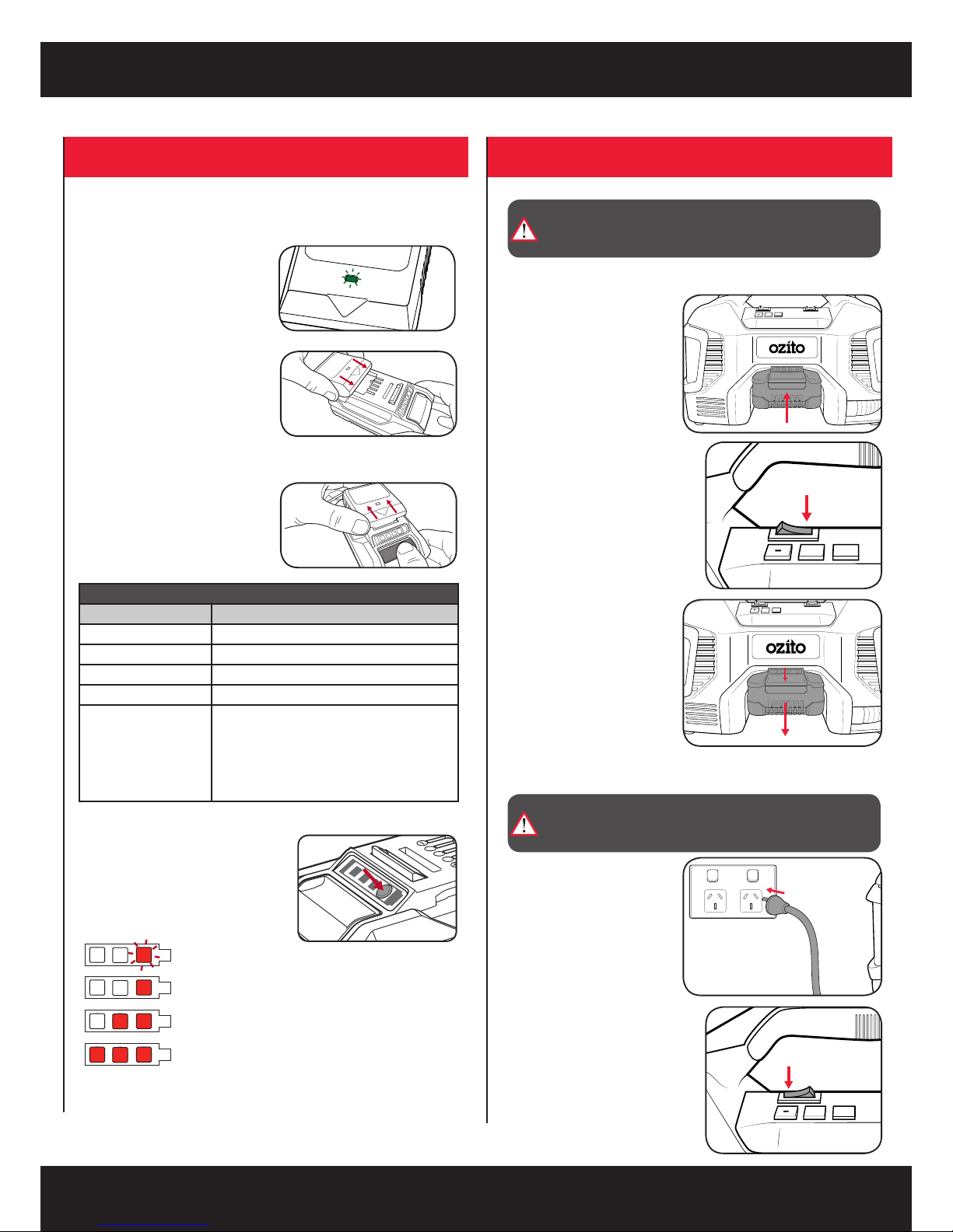
Battery Charge Indicator
The purchased battery is equipped with a
battery charge indicator to show the state of
the battery charge.
Press the charge indicator button and look to
see which LED lights.
Battery requires
immediate charging
Low state of charge, requires charging soon.
Mid state of charge
Full state of charge.
Note: The battery needs to be removed from the tool to check the state of charge.
1 Connect the charger into a mains power outlet.
4 The charger LED will illuminate red signifying that the battery is charging.
3 With the battery sitting on a at
surface, align the raised ribs on the
battery with the recess in the charger
and slide onto the battery ensuring a
rm connection.
2 The charger LED will ash green
showing power is being supplied
to the charger.
5 When removing the charger from the
battery, rst press the battery release
tab, then slide the charger from its
position.
Charging your lithium ion battery - Eco Charger
Charger LED Indicator
LED Indicator Situation
GREEN (Flashing) Stand By (no battery pack is inserted)
RED (Illuminated) Battery is charging (low charge)
GREEN (Illuminated) Battery is fully charged
RED (Flashing) Battery or Charger fault
RED & GREEN (Flashing) Battery pack is too hot or too cold (remove battery from
charger and store at room temperature 20ºC. Insert
battery again when at correct charging temperature). If
this happens again, the battery is defective and needs
to be replaced.
Connecting to a 240V (AC) Outlet
Inserting & Removing the Battery (not included)
2 To switch the unit on, press the
power mode switch into the DC
position.
3 To remove, press and hold the
battery release tab and pull
the battery away from the
tool.
2 To switch the unit on, press the
power mode switch into the
AC position.
1 Align the ribs of the battery
with the recess at the front
of the unit and push in until it
clicks into place.
1 Remove the power cord from
the compartment at the base
of the inator and connect to a
240V outlet.
AC
DC
I
0
I
+
MODE
I
AC
DC
I
0
I
+
MODE
I
AC
DC
I
0
I
+
MODE
I
AC
DC
I
0
I
+
MODE
I
a
b
AC
DC
I
0
I
+
MODE
I
WARNING! THE 240V POWER SUPPLY SHOULD BE
PROTECTED BY A RESIDUAL CURRENT DEVICE (RATED
AT 30MA OR LESS).
WARNING! BEFORE CONNECTING TO A POWER
SUPPLY, ENSURE THE OPERATING MODE SWITCH IS IN
THE OFF POSITION “0”.
 Loading...