

Ozito PXCPPS-018U Original Instructions Manual
EH-Art. No.: 34.108.16 I-No.: 11016
SPECIFICATIONS
Input: 18V
Bar Length: 200mm
Cutting Length Max.: 170mm
Chain Speed: 3.76m/s
Oil Tank Capacity: 125ml
Length: 1.83 - 2.77m
Weight (without battery: 3.9kg
WHAT’S IN THE BOX
Pole
Battery & Charger sold separately
CORDLESS
POLE PRUNER
ORIGINAL INSTRUCTIONS
ozito-diy.co.uk
Guide Bar Cover
Pruner Head
Chain
Guide Bar
Rear Handle
Shoulder Strap
Auxiliary Handle
PXCPPS-018U
WARRANTY
0816
All of our products undergo strict quality checks to ensure that they reach you in perfect
condition. In the unlikely event that your device develops a fault, please contact our service
department at the address shown on this guarantee card. You can also contact us by
telephone using the customer service number shown. Please note the following terms under
which guarantee claims can be made:
1. These warranty terms regulate additional warranty services, which the manufacturer
mentioned below promises to buyers of its new products in addition to their statutory
guarantee claims are not affected by this guarantee. Our guarantee is free of charge to you.
2. The warranty services only covers defects due to material or manufacturing faults on
a product which you have bought from the manufacturer mentioned below are limited to
either the rectication of said defects on the product or the replacement of the product,
whichever we prefer.
Please note that our devices are not designed for use in commercial, trade or professional
applications. A guarantee contract will not be created if the device has been used by
commercial, trade or industrial business or has been exposed to similar stresses during the
guarantee period.
3. The following are not covered by our guarantee:
- Damage to the device caused by a failure to follow the assembly instructions or due to
incorrect installation, a failure to follow the operating instructions (for example connecting
it to an incorrect mains voltage or current type) or a failure to follow the maintenance and
safety instructions or by exposing the device to abnormal environmental conditions or by
lack of care and maintenance.
- Damage to the device caused by abuse or incorrect use (for example overloading the
device or the use or unapproved tools or accessories), ingress of foreign bodies into the
device (such as sand, stones or dust, transport damage), the use of force or damage caused
by external forces (for example by dropping it).
- Damage to the device or parts of the device caused by normal or natural wear or tear or by
normal use of the device.
4. Your Product is guaranteed for a period of 60 months from the original date of purchase
and is intended for DIY (Do It Yourself) use only. Lithium Ion batteries and chargers are
covered by a 12 month warranty. Warranty excludes consumable parts. Guarantee claims
should be submitted before the end of the guarantee period within two weeks of the defect
being noticed. No guarantee claims will be accepted after the end of the guarantee period.
The original guarantee period remains applicable to the device even if repairs are carried
out or parts are replaced. In such cases, the work performed or parts tted will not result
in an extension of the guarantee period, and no new guarantee will become active for the
work performed or parts tted. This also applies if an on-site service is used.
IN ORDER TO MAKE A CLAIM UNDER THIS WARRANTY YOU MUST RETURN THE PRODUCT TO
THE PLACE OF PURCHASE WITH YOUR REGISTER RECEIPT.
Please refer to the restrictions of this warranty concerning wearing parts, consumables and
missing parts as set out in the service information in these operating instructions.
CUSTOMER SERVICE HELPLINE
GB: 0151 294 4488
IRL: 1850 882711
Ozito-diy.co.uk
OZITO UK Unit 9 Stadium Court, Wirral International Business Park, Plantation Road, Bromborough, Wirral, CH62 3QG

KNOW YOUR PRODUCT
SETUP & PREPARATION
1. ASSEMBLY
1. Chain
2. Guide Bar
3. Oil Cap
4. Side Cover
5. Pivoting Pruner Head Release
6. Telescopic Tube Lock
7. Main Tube
8. Auxiliary Handle
9. Shoulder Strap Holder
10. Assembly Nut
11. Pivoting Handle Release
12. Rear Handle
13. Chain Cover Lock
14. Chain Tension Adjustment Dial
15. Switch Lock
16. Auxiliary Handle Lever
17. Trigger Switch
18. Battery Seating
19. Mounting Attachment Lever
CORDLESS POLE PRUNER
1
2
3
4
5
6
7
8
ONLINE MANUAL
Scan this QR Code with your mobile device to take you to
the online manual.
15
16
10
11
12
13 14
9
17 18 19
BATTERY & CHARGER
(sold separately)
This tool is compatible with all battery and chargers from
the Ozito Power X Change Range.
For example: Batteries PXBP-200U (2Ah / 18V) &
PXBP-400U (4Ah / 18V). Charger: PXCG-030U (18V).
CAUTION: ENSURE THE TOOL IS OFF & THE BATTERY
REMOVED BEFORE PERFORMING ANY OF THE FOLLOWING
OPERATIONS.
Fitting Rear Handle
1. Push the rear handle fully
onto tube aligning the
internal prongs.
2. Screw tight with
the assembly nut.
Fitting Auxiliary Handle
1. Place the Auxiliary Handle onto
the mounting attachment.
2. Pass the bolt through the auxiliary handle and screw the lever to the end
of the bolt.
3. Select the most comfortable
position and close the lever
to lock the auxiliary handle in
position.
2. TENSIONING THE CHAIN
Note: The Lock Button will “CLICK” back to the left (original position) when
the pruner head is correctly secured in place.
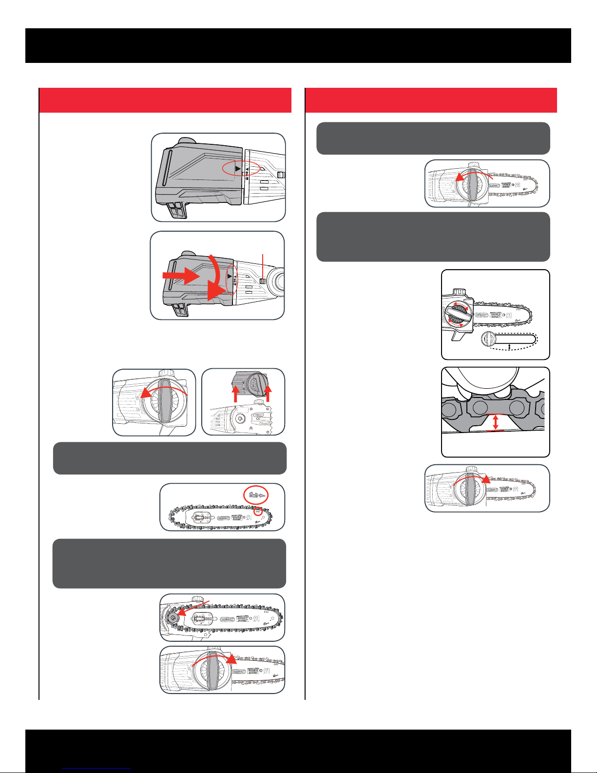
3 - 4mm gap is
the ideal tension
Fitting Pruner Head
1. Align the pruner head and
the motor head so the
arrows on both coincide.
2. (a) Press the pruner head
against the motor head.
This will cause the lock
button to be pushed to the
right.
(b) Turn the pruner head
clockwise. The pruner head
will lock onto the motor
head and is then secured
in place.
Lock Button
a
b
Note: Only tighten the chain cover locking knob securely once the chain
tension has been adjusted (see: Tensioning the chain.)
CAUTION: THE CHAIN HAS SHARP EDGES. FOR YOUR
OWN SAFETY, PLEASE WEAR WORK GLOVES.
IMPORTANT: IF THE CHAIN IS INSTALLED BACKWARDS
(CHAIN CUTTERS ARE FACING IN THE OPPOSITE
DIRECTION OF ROTATION) THE POLE PRUNER WILL
VIBRATE EXCESSIVELY AND NOT CUT.
Fitting Guide Bar & Chain
1. Loosen the
chain cover
lock and
remove the
side cover.
2. Place the chain in the groove
of the guide bar as shown.
Refer to the image printed on
the guide bar that indicates
the direction that the chain
should face.
Sprocket
3. Place onto the mount,
ensuring that the chain sits
around the chain sprocket.
4 Re-mount and nger-tighten
the side cover with the chain
cover lock.
1. Loosen the chain
cover lock. Do not
remove the side
cover.
CAUTION: IF YOU TRY TO ROTATE THE CHAIN TENSIONING
ADJUSTMENT DIAL WHILST THE CHAIN COVER LOCK IS
TIGHT, IT WILL RESULT IN THE CHAIN NOT LOOSENING
AND POSSIBLE DAMAGE TO THE MECHANISM.
2. Adjust the chain tension with
the chain tensioning adjustment
dial. Turning the dial CLOCKWISE
increases the chain tension,
turning it COUNTER-CLOCKWISE
decreases the chain tension.
For the correct chain tension, rmly
pull up on the chain at the middle
of the top of the exposed guide bar.
When the chain is pulled up to its
highest point, the bottom tip of the
links should only just stay in the track
[middle of the guide bar]
CAUTION: THE CHAIN HAS SHARP EDGES. FOR YOUR
OWN SAFETY, PLEASE WEAR WORK GLOVES.
3. After the chain has been
accurately tensioned, lock the
guide bar in place with the
chain cover locking knob.
Note: Proper tension of the chain is extremely important and must be
checked before starting, as well as during any cutting operation.
Taking the time to make adjustments to the chain will result in
improved cutting performance and prolonged chain life.
 Loading...