

Ozito PXCPPA-200 Instruction Manual
SPECIFICATIONS
Voltage: 18V
Bar Length: 200mm
Cutting Length Max.: 170mm
Chain Speed: 3.76m/s
Oil Tank Capacity: 125ml
Weight: 1.24kg
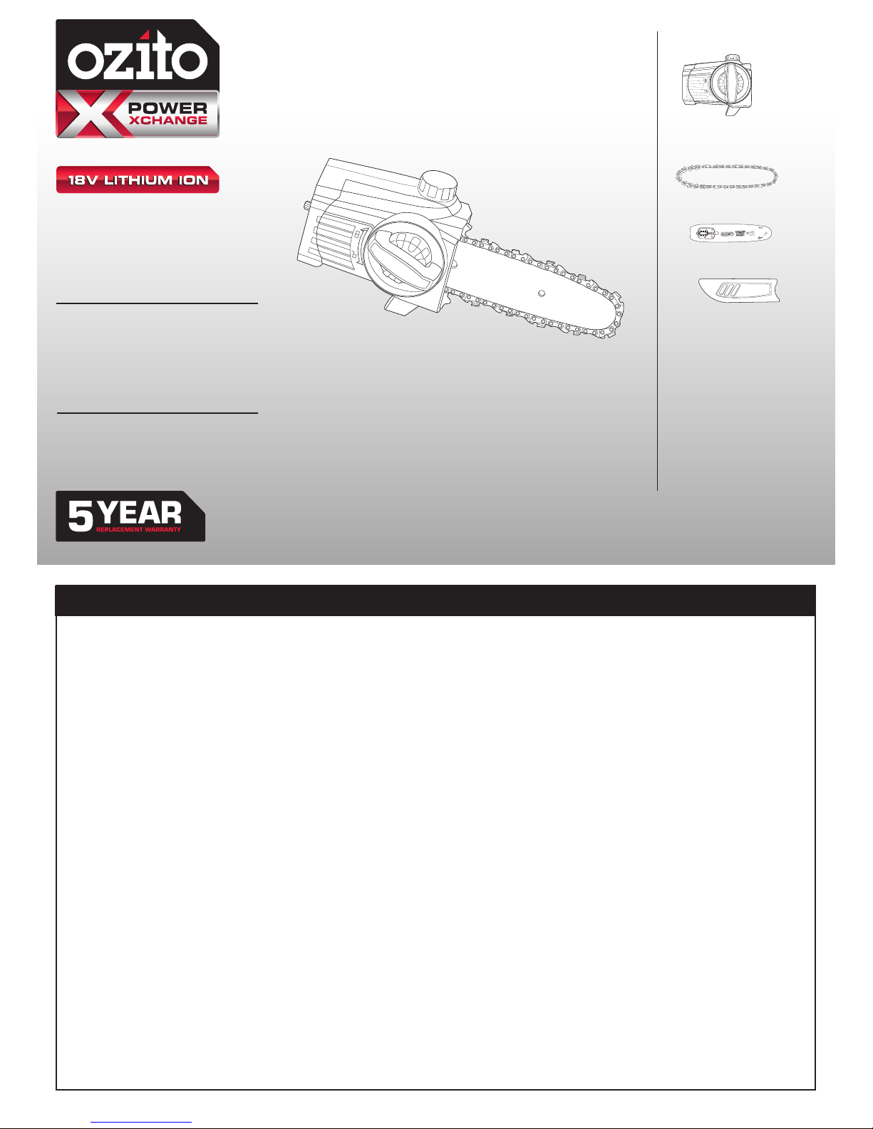
WHAT’S IN THE BOX
CORDLESS POLE
PRUNER HEAD
INSTRUCTION MANUAL
ozito.com.au
Guide Bar Cover
Pruner Head
Chain
Guide Bar
PXCPPA-200
IN ORDER TO MAKE A CLAIM UNDER THIS WARRANTY YOU
MUST RETURN THE PRODUCT TO YOUR NEAREST BUNNINGS
WAREHOUSE WITH YOUR BUNNINGS REGISTER RECEIPT. PRIOR TO
RETURNING YOUR PRODUCT FOR WARRANTY PLEASE TELEPHONE
OUR CUSTOMER SERVICE HELPLINE:
Australia 1800 069 486
New Zealand 0508 069 486
WARRANTY
TO ENSURE A SPEEDY RESPONSE PLEASE HAVE THE MODEL
NUMBER AND DATE OF PURCHASE AVAILABLE. A CUSTOMER
SERVICE REPRESENTATIVE WILL TAKE YOUR CALL AND
ANSWER ANY QUESTIONS YOU MAY HAVE RELATING TO THE
WARRANTY POLICY OR PROCEDURE.
OZITO Australia/New Zealand (Head Ofce) 1-23 Letcon Drive, Bangholme, Victoria, Australia 3175.
The benets provided under this warranty are in addition to other rights and
remedies which are available to you at law.
Our goods come with guarantees that cannot be excluded at law. You are entitled to
a replacement or refund for a major failure and for compensation for any other
reasonably foreseeable loss or damage. You are also entitled to have the goods
repaired or replaced if the goods fail to be of acceptable quality and the failure
does not amount to a major failure.
Generally you will be responsible for all costs associated with a claim under this
warranty, however, where you have suffered any additional direct loss as a result of
a defective product you may be able to claim such expenses by contacting our
customer service helpline above.
0617
WARNING
The following actions will result in the warranty being
void.
• If the tool has been operated on a supply voltage other
than that specied on the tool.
• If the tool shows signs of damage or defects caused
by or resulting from abuse, accidents or alterations.
• Failure to perform maintenance as set out within the instruction manual.
• If the tool is disassembled or tampered with in any way.
5 YEAR REPLACEMENT WARRANTY
Your Product is guaranteed for a period of 60 months from the original date of
purchase and is intended for DIY (Do It Yourself) use only. If a product is defective it
will be replaced in accordance with the terms of this warranty. Lithium Ion
batteries and chargers are covered by a 36 month
warranty Warranty excludes consumable parts, for example: guide bar, chain
and guide bar cover
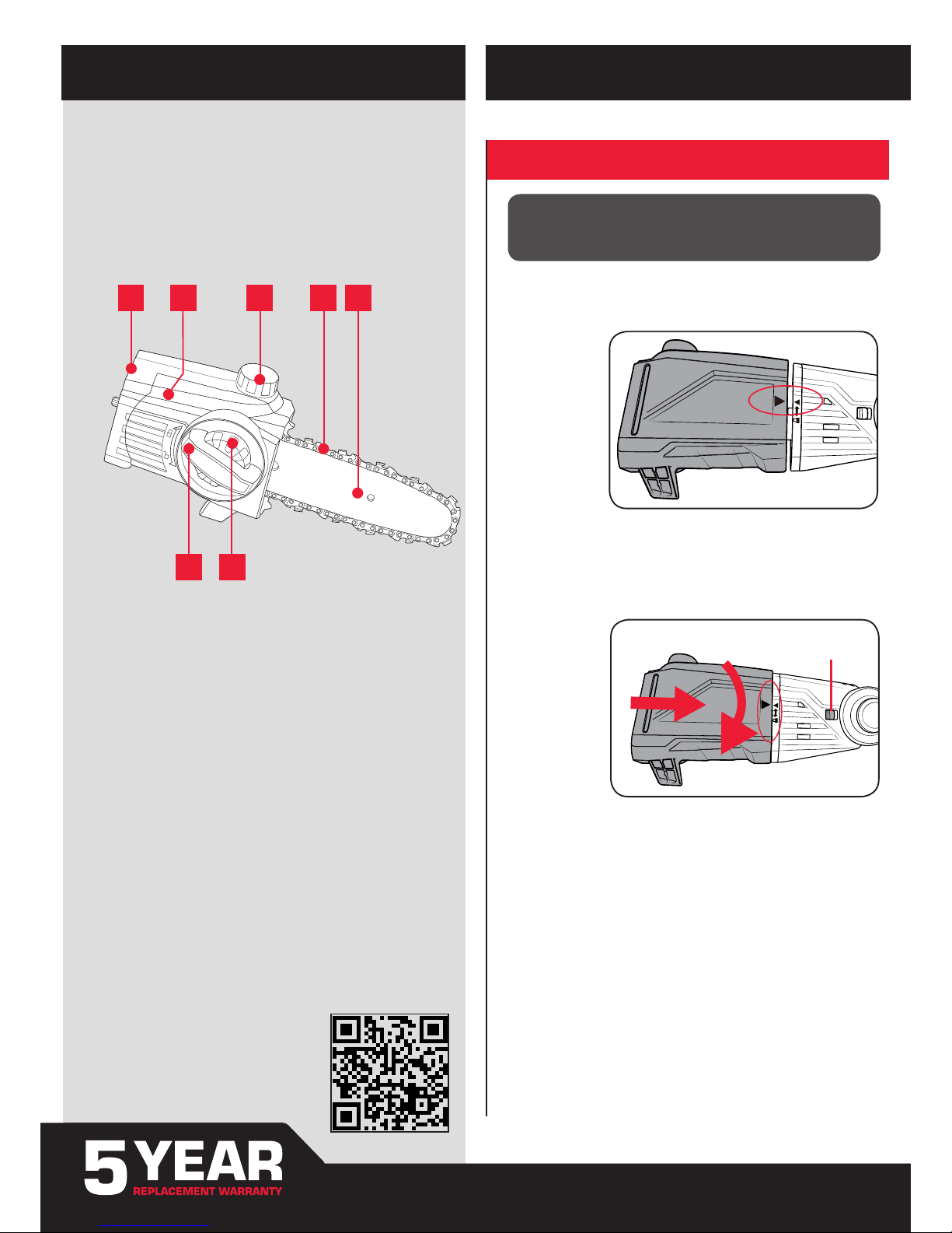
KNOW YOUR PRODUCT
SETUP & PREPARATION
1. ASSEMBLY
1. Pruner Head
2. Side Cover
3. Oil Cap
4. Chain
5. Guide Bar
6. Chain Cover Lock
7. Chain Tension Adjustment Dial
POLE PRUNER HEAD
1 2 3 4 5
76
ONLINE MANUAL
Scan this QR Code with your
mobile device to take you to the
online manual.
Note: The Lock Button will “CLICK” back to the left (original position) when
the pruner head is correctly secured in place.
CAUTION: ENSURE THE TOOL IS OFF & THE BATTERY
REMOVED BEFORE PERFORMING ANY OF THE FOLLOWING
OPERATIONS.
Fitting Pruner Head
1. Align the pruner head and the motor head so the arrows on both coincide.
2. (a) Press the pruner head against the motor head. This will cause the lock
button to be pushed to the right.
(b) Turn the pruner head clockwise. The pruner head will lock onto the
motor head and is then secured in place.
Lock Button
a
b
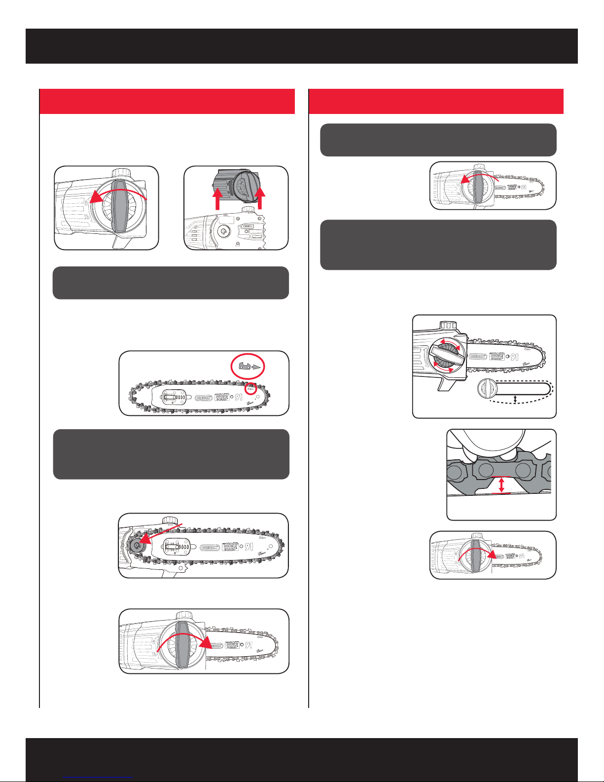
2. TENSIONING THE CHAIN
Sprocket
3 - 4mm gap is
the ideal tension
Note: Only tighten the chain cover locking knob securely once the chain
tension has been adjusted (see: Tensioning the Chain.)
CAUTION: THE CHAIN HAS SHARP EDGES. FOR YOUR
OWN SAFETY, PLEASE WEAR WORK GLOVES.
IMPORTANT: IF THE CHAIN IS INSTALLED BACKWARDS
(CHAIN CUTTERS ARE FACING IN THE OPPOSITE
DIRECTION OF ROTATION) THE POLE PRUNER WILL
VIBRATE EXCESSIVELY AND NOT CUT.
Fitting Guide Bar & Chain
1. Loosen the chain cover lock and remove the side cover.
2. Place the chain in the groove of the guide bar as shown. Refer to the
image printed on the guide bar that indicates the direction that the chain
should face.
Sprocket
3. Place onto the mount, ensuring that the chain sits around the chain
sprocket.
Sprocket
4 Re-mount and nger-tighten the side cover with the chain cover lock.
1. Loosen the chain cover
lock. Do not remove the
side cover.
Sprocket
CAUTION: IF YOU TRY TO ROTATE THE CHAIN TENSIONING
ADJUSTMENT DIAL WHILST THE CHAIN COVER LOCK IS
TIGHT, IT WILL RESULT IN THE CHAIN NOT LOOSENING
AND POSSIBLE DAMAGE TO THE MECHANISM.
2. Adjust the chain tension with the chain tensioning adjustment dial.
Turning the dial CLOCKWISE increases the chain tension, turning it
COUNTER-CLOCKWISE decreases the chain tension.
For the correct chain tension, rmly pull
up on the chain at the middle of the
top of the exposed guide bar. When the
chain is pulled up to its highest point,
the bottom tip of the links should only
just stay in the track [middle of the
guide bar]
CAUTION: THE CHAIN HAS SHARP EDGES. FOR YOUR
OWN SAFETY, PLEASE WEAR WORK GLOVES.
3. After the chain has been
accurately tensioned, lock the
guide bar in place with the
chain cover locking knob.
Sprocket
Note: Proper tension of the chain is extremely important and must be
checked before starting, as well as during any cutting operation.
Taking the time to make adjustments to the chain will result in
improved cutting performance and prolonged chain life.
 Loading...