

Ozito PXCLTS-0182 Instruction Manual
STANDARD EQUIPMENT
CORDLESS
LINE TRIMMER
INSTRUCTION MANUAL
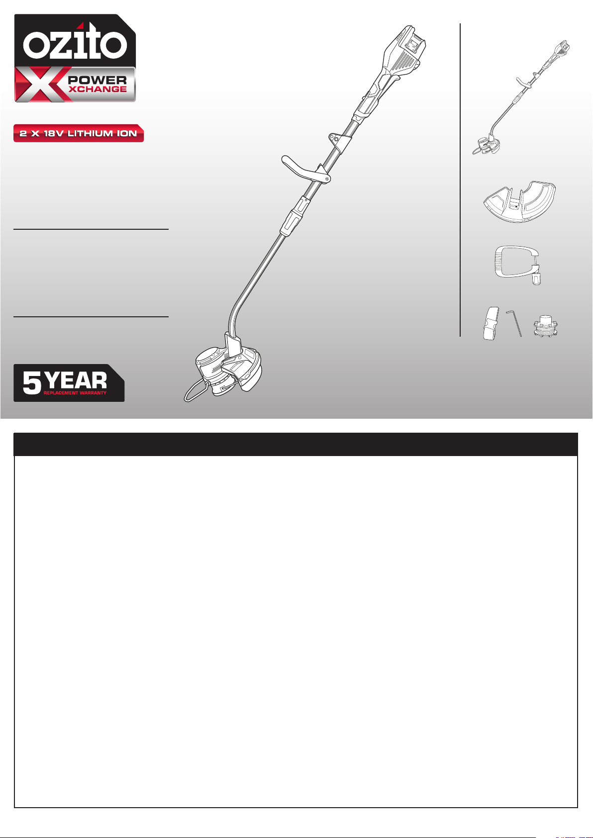
SPECIFICATIONS
Voltage: 18V x 2
No Load Speed: 0 - 9,000/min
Cutting Diameter: 300mm
Cutting Line: Ø2.0mm x 8m
Line Feed: Bump
Weight: 3.1kg
ozito.com.au
Line Trimmer
Safety Guard
Adjustable Handle
Shoulder Strap, Hex Key and
Replacement Spool & Line
PXCLTS-0182
WARRANTY
IN ORDER TO MAKE A CLAIM UNDER THIS WARRANTY YOU MUST
RETURN THE PRODUCT TO YOUR NEAREST BUNNINGS WAREHOUSE
WITH YOUR BUNNINGS REGISTER RECEIPT. PRIOR TO RETURNING
YOUR PRODUCT FOR WARRANTY PLEASE TELEPHONE OUR CUSTOMER
SERVICE HELPLINE:
Australia 1800 069 486
New Zealand 0508 069 486
TO ENSURE A SPEEDY RESPONSE PLEASE HAVE THE MODEL
NUMBER AND DATE OF PURCHASE AVAILABLE. A CUSTOMER
SERVICE REPRESENTATIVE WILL TAKE YOUR CALL
AND ANSWER ANY QUESTIONS YOU MAY
HAVE RELATING TO THE WARRANTY POLICY
OR PROCEDURE.
WARNING
The following actions will result in the warranty being
void.
• If the tool has been operated on a supply voltage other
than that specied on the tool.
• If the tool shows signs of damage or defects caused
by or resulting from abuse, accidents or alterations.
• Failure to perform maintenance as set out within the instruction manual.
• If the tool is disassembled or tampered with in any way.
• Professional, industrial or high frequency use.
The benets provided under this warranty are in addition
to other rights and remedies which are available to you at law.
Our goods come with guarantees that cannot be excluded
at law. You are entitled to a replacement or refund for a major failure and for
compensation for any other reasonably foreseeable loss or damage. You are also
entitled to have the goods repaired
or replaced if the goods fail to be of acceptable quality and the failure does not
amount to a major failure.
Generally you will be responsible for all costs associated with
a claim under this warranty, however, where you have suffered
any additional direct loss as a result of a defective product you
may be able to claim such expenses by contacting our customer service helpline
above.
5 YEAR REPLACEMENT WARRANTY
Your Product is guaranteed for a period of 60 months from the original date of
purchase and is intended for DIY (Do It Yourself) use only. If a product is defective it
will be replaced in accordance with the terms of this warranty. Lithium Ion
batteries and chargers are covered by a 36 month
warranty. Warranty excludes consumable parts, for example: line & spool,
shoulder strap and included accessories.
OZITO Australia/New Zealand (Head Ofce) 1-23 Letcon Drive, Bangholme, Victoria, Australia 3175.
0618
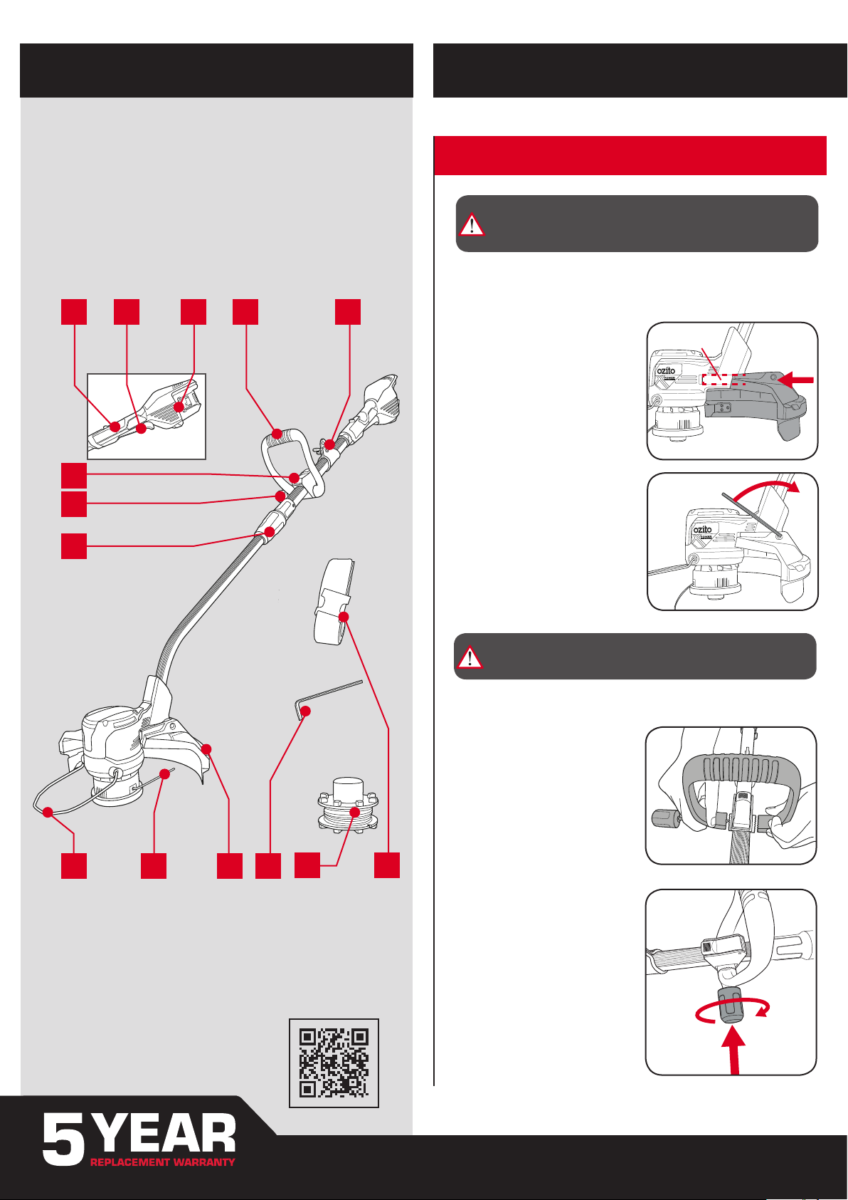
KNOW YOUR PRODUCT
RECESS
SETUP & PREPARATION
CORDLESS LINE TRIMMER
1. Safety Switch
2. Variable Speed Trigger
3. Battery Seating
4. Adjustable Handle
5. Shoulder Strap Bracket
6. Adjustable Handle Lever
7. Adjustable Handle Knob
8. Shaft Lock Collar
9. Edging Guide
10. Cutting Line
11. Safety Guard
1 2 3 4
6
7
8
5
1. ASSEMBLY
WARNING! ENSURE THE TOOL IS SWITCHED
OFF AND BATTERY DISCONNECTED BEFORE
PERFORMING ANY OF THE FOLLOWING TASKS.
Fitting the Safety Guard
1. With the provided hex key remove the socket head bolt from the safety
guard.
2. Align the tabs of the safety guard
with the recess in the back of the
line trimmer motor.
3. Slide the safety guard in place and
secure with the socket head bolt.
Tighten with the hex key.
9
10 11
12
ACCESSORIES
12. Hex Key
13. Replacement Spool & Line
14. Shoulder Strap
BATTERY & CHARGER
This tool is compatible with all battery and chargers from
the Ozito Power X Change Range
ONLINE MANUAL
Scan this QR Code with your mobile
device to take you to the online manual.
WARNING! NEVER USE THE GRASS TRIMMER
UNLESS THE SAFETY GUARD IS PROPERLY FITTED.
Fitting the Adjustable Handle
1. Fit the adjustable handle onto the
mounting bracket.
Note: You will need to carefully ex
the adjustable handle just enough to
slip over the mounting bracket. Do not
over ex as this can damage or break
the adjustable handle.
13 14
2. Place the adjustable handle on
the mounting bracket, then pass
the screw with washer through
the handle and onto the mounting
bracket.
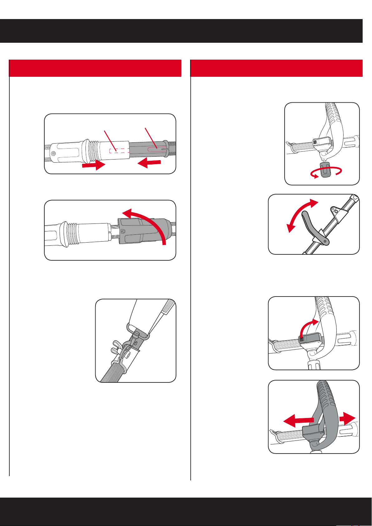
2. ADJUSTMENTS
TA B
RECESS
Shaft Assembly
1. Push both halves of the shaft together aligning the tab with the recess.
2. Screw tight with the shaft lock collar.
Adjusting the Handle angle
1. Loosen the adjustable handle
knob.
2. Rotate the handle into
the desired position and
tighten the knob to lock
in place.
Attaching the Shoulder Strap
Fasten the carabiner hook to the
shoulder strap bracket on the shaft.
Adjusting the Handle position
1. Release the adjustable
handle lever.
2. Slide the handle into
the desired position and
then lock in place with
the lever.
 Loading...