

Ozito MCS-2355 Instruction Manual

METAL
STANDARD EQUIPMENT
CUT-OFF SAW
2300W
INSTRUCTION MANUAL
SPECIFICATIONS
Motor: 2300W
Input: 230
No Load Speed: 4,400/min
Cut-off Wheel
Max. Diameter: 356 x 3mm (14” x 1/8’’)
Arbour Size: 25.4mm
Cutting Angle Capacity: 0
Max. Cutting Capacities @90°: Round steel 130mm
Square steel 120mm
Rectangle steel 120x130mm
Angle steel 140x140mm
@45°: 90x100mm
Weight: 16.8kg
ozito.com.au
–
240V~50Hz
–
45º Left, 0 – 15º Right
Metal Cut-off Saw
Cut-off Wheel (Fitted)
Hex Key
MCS-2355
WARRANTY
IN ORDER TO MAKE A CLAIM UNDER THIS
WARRANTY YOU MUST RETURN THE PRODUCT
TO YOUR NEAREST BUNNINGS WAREHOUSE WITH
YOUR BUNNINGS REGISTER RECEIPT. PRIOR TO
RETURNING YOUR PRODUCT FOR WARRANTY
PLEASE TELEPHONE OUR CUSTOMER SERVICE
HELPLINE:
Australia 1800 069 486
New Zealand 0508 069 486
TO ENSURE A SPEEDY RESPONSE PLEASE
HAVE THE MODEL NUMBER AND DATE OF
PURCHASE AVAILABLE. A CUSTOMER SERVICE
REPRESENTATIVE WILL TAKE YOUR CALL
AND ANSWER ANY QUESTIONS YOU MAY
HAVE RELATING TO THE WARRANTY POLICY
OR PROCEDURE.
The benefits provided under this warranty are in addition
to other rights and remedies which are available to you at law.
Our goods come with guarantees that cannot be excluded
at law. You are entitled to a replacement or refund for a major
failure and for compensation for any other reasonably foreseeable
loss or damage. You are also entitled to have the goods repaired
or replaced if the goods fail to be of acceptable quality and the
failure does not amount to a major failure.
Generally you will be responsible for all costs associated with
a claim under this warranty, however, where you have suffered
any additional direct loss as a result of a defective product you
may be able to claim such expenses by contacting our customer
service helpline above.
3 YEAR REPLACEMENT WARRANTY
Your product is guaranteed for a period of 36 months from
the original date of purchase. If a product is defective it will
be replaced in accordance with the terms of this warranty.
Warranty excludes consumable parts, for example: carbon brushes,
spanners, cutting disc, accessories.
WARNING
The following actions will result in the warranty being void.
• If the tool has been operated on a supply voltage other
than that specified on the tool.
• If the tool shows signs of damage or defects caused
by or resulting from abuse, accidents or alterations.
• Failure to perform maintenance as set out within the
instruction manual.
• If the tool is disassembled or tampered with in any way.
• Professional, industrial or high frequency use.
OZITO
Australia/New Zealand (Head Office) 1-23 Letcon Drive, Bangholme, Victoria, Australia 3175.
0919
3
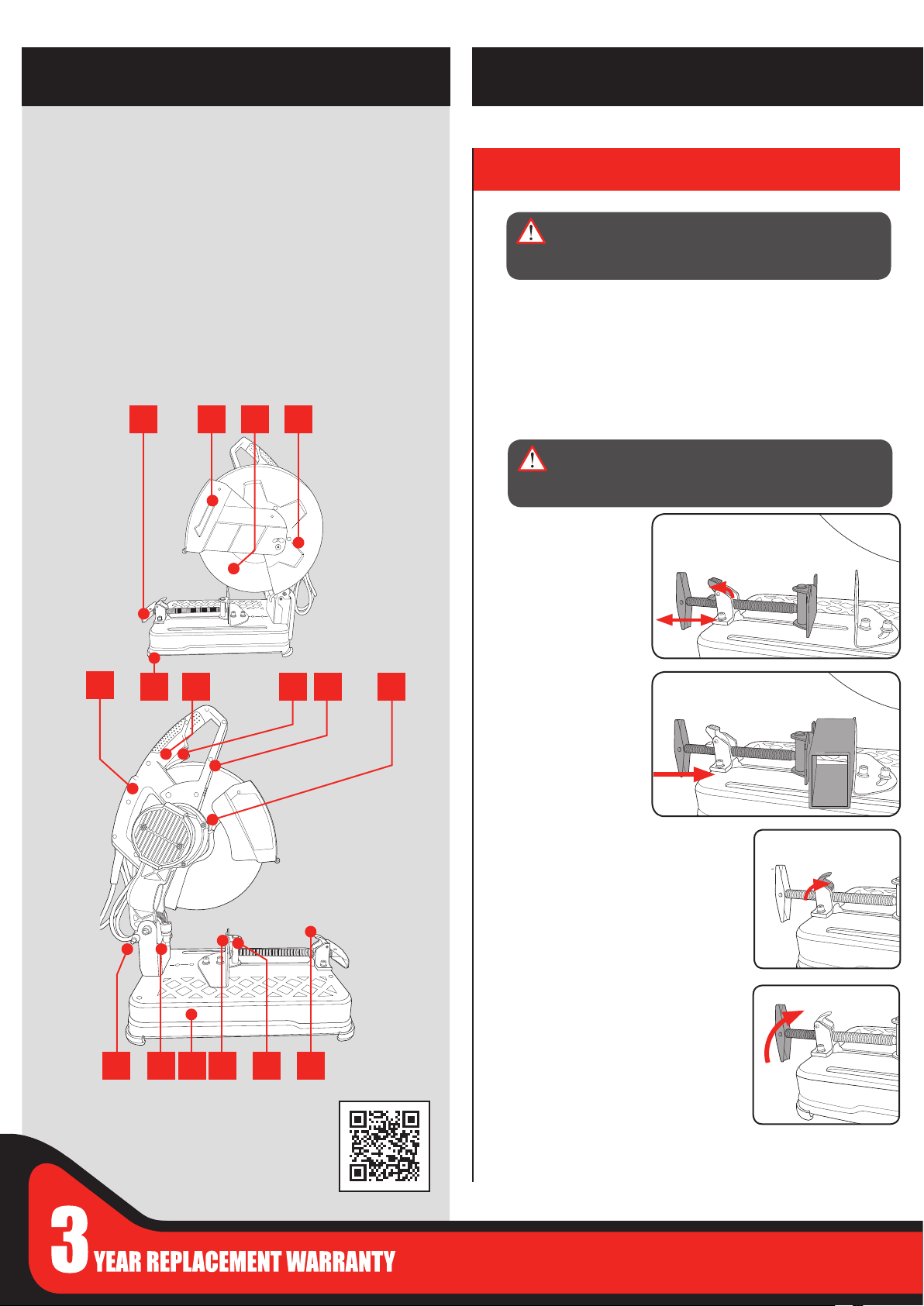
KNOW YOUR PRODUCT
SETUP & PREPARATION
METAL CUT-OFF SAW
1. Vice handle
2. Lower guard
3. Cut-o wheel
4. Upper guard
5. Carry handle
6. Rubber feet
7. Lock-o button
8. Trigger switch
9. Main handle
1
2 3 4
10. Spindle lock button
11. Lock down pin
12. Depth stop
13. Base
14. Fence
15. Vice
16. Quick release vice lock
17. Hex Key Storage
18. Hex Key
1. ADJUSTMENTS
WARNING! ENSURE THAT THE TOOL IS TURNED
OFF AND DISCONNECTED FROM THE POWER
SUPPLY BEFORE PERFORMING ANY OF THE
FOLLOWING OPERATIONS.
Your Metal Cut-O Saw is used for cutting steel such as pipe, box
section, rectangular, angle iron and steel bars. The saw can cut at
angles from 0 to 45º left & 0 to 15º right, it features a three position
fence that permits an extended cutting range. The quick release vice
allows fast adjustment whilst the lock-o button prevents accidental
operation. It is intended for DIY use only.
Adjusting the vice
WARNING! ENSURE THAT THE VICE SECURING
BOLTS AND VICE ARE FIRMLY TIGHTENED BEFORE
USE TO PREVENT THE WORKPIECE MOVING AND
RISK OF PERSONAL INJURY.
The vice can be
adjusted quickly by
lifting the quick release
vice lock and pushing
forward or pulling back
on the vice handle.
5
7 8
6 9 10
11 12 13 14 15 16
ONLINE MANUAL
Scan this QR Code with your
mobile device to take you to
the online manual.
1. Place your work
piece in between the
fence and vice.
2. Lift the quick release
vice lock and push
the vice forward.
3. Once the vice hits the work piece push
down the quick release vice lock.
4. Rotate the vice handle in a clockwise
direction to secure the work piece in
position.
5. To remove an object from the vice,
rotate the vice handle in an anti-
clockwise direction until the vice jaws
are loose. The work piece can now be
removed.
Note: The quick release vice lock cannot be lifted until the vice jaws
have been loosened.
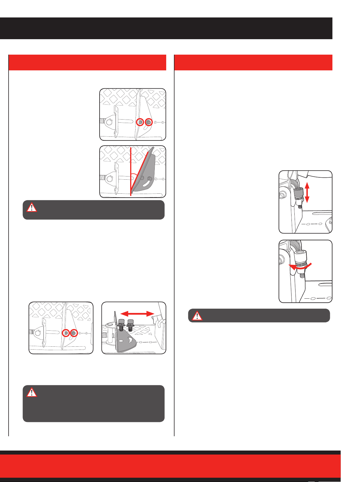
Adjusting the cutting angle
1. To change the cutting angle
loosen the two bolts securing
the fence using the hex key
supplied.
2. Move the rear fence to the
desired angle using the scale
as a guide.
Depth stop
Note: Ensure that the depth stop is adjusted to the correct height
before commencing operation.
The adjustable depth stop is threaded into the base of the machine at
the rear.
The travel of the cut-o wheel can be controlled by raising and lowering
the depth stop bolt.
This feature is particularly useful to prevent contact with the work
bench surface when a new cut-o wheel is tted or to increase cut-o
wheel travel as the cut-o wheel wears.
The depth stop should be checked and adjusted every time
a new cut-o wheel is tted.
3. Tighten the two bolts to secure
the fence in position.
WARNING! ONLY PERFORM ANGLE CUTS WHEN
THE FENCE IS SET AT THE MOST FORWARD
POSITION (REFER TO ADJUSTING THE FENCE).
Note: For accurate cuts, test the cutting angle on some similar scrap
material and adjust the angle to suit your requirements. The scale is
only a guide.
Adjusting the fence
The spacing between the vice and the fence as supplied is 170mm.
When cutting wider materials the rear fence will need to be adjusted to
the rear position. When cutting narrow work pieces the fence should
be positioned in the most forward position.
1. To adjust, loosen and remove the two bolts securing the fence
using the Hex key.
1. Loosen the depth stop with the hex
key supplied.
2. Increase or decrease the height
of the depth stop.
3. Tighten the depth stop knurled lock nut
with your ngers.
WARNING! DO NOT REMOVE OR OPERATE
WITHOUT THE DEPTH STOP!
2. Move the fence backwards or
3. Tighten the two bolts to secure
the fence in position.
WARNING! NARROW WORKPIECES MAY NOT BE
SECURED SAFELY WHEN USING AN INTERVAL
TOO WIDE FOR THE FENCE. ENSURE THAT THE
FENCE IS SET TO THE MOST FORWARDS POSITION
THAT ALLOWS THE WORKPIECE TO BE CLAMPED
SECURELY.
forwards to one of the other
two xing positions.
 Loading...