

User & Superuser Manual intelliControl Siemens v.14.1.2022 Page 1 of 28
User & Superuser Manual
Touch screen Controller
intelliControl Siemens
Manufacturer:
OXYMAT – Slovakia, s.r.o.
Vaďovce 87
916 13 Vaďovce
User & Superuser Manual intelliControl Siemens v.14.1.2022 Page 2 of 28
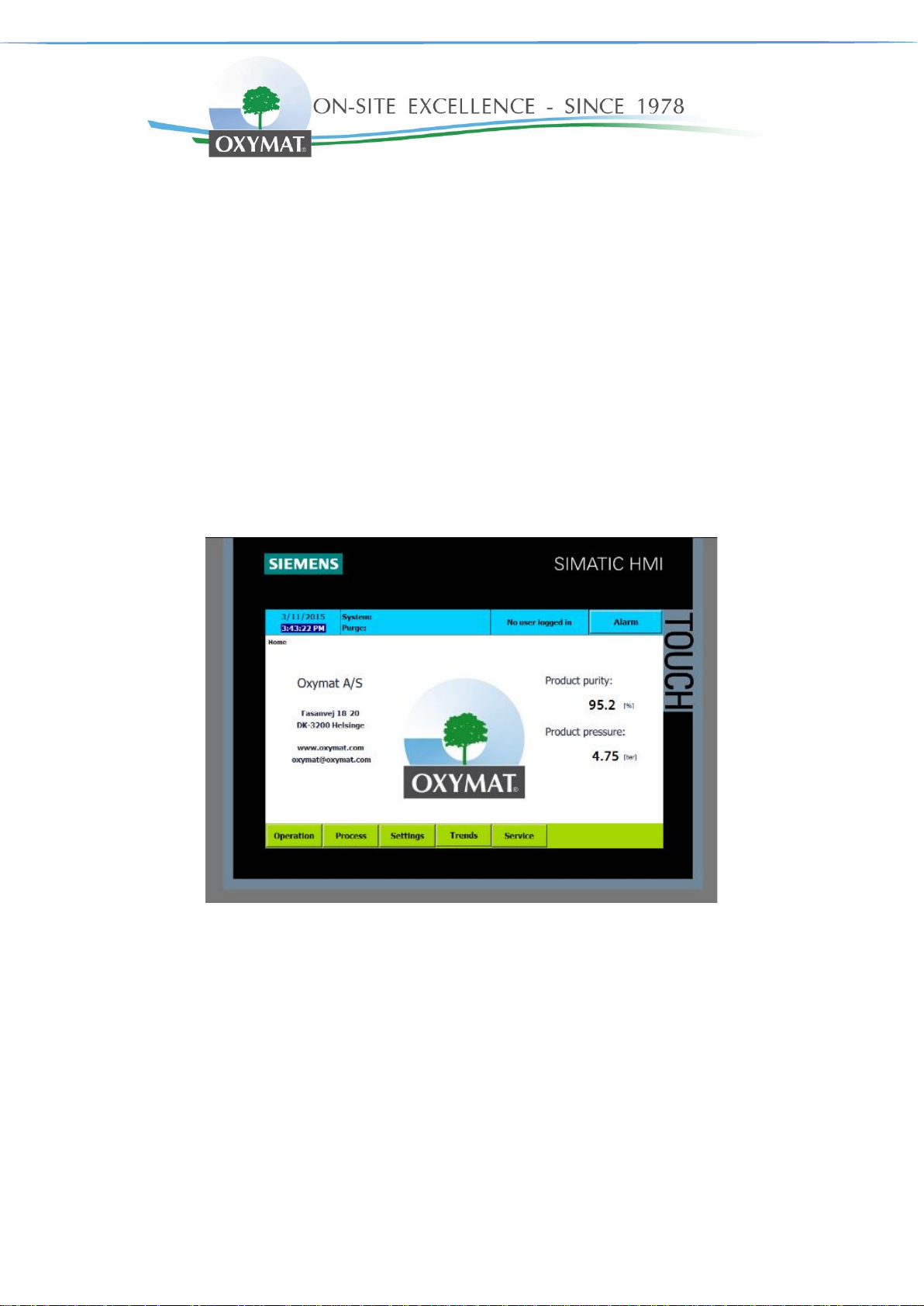
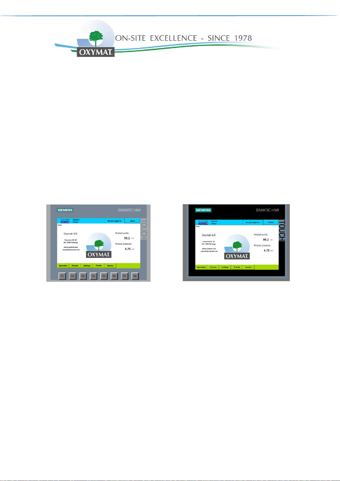
Siemens SIMATIC HMI TP700 comfort – for
standard functionality + remote control and view
Siemens SIMATIC HMI KTP700 basic for
standard functionality
Valid for:
intelliControl Siemens X1-X2
Software version: ≥ 1.09
SIMATIC KTP700 BASIC
SIMATIC TP700 COMFORT
COPYRIGHT NOTICE
Any unauthorized use or copying of the contents or any part thereof is prohibited.
This applies in particular to trademarks, model & functionality names, and pictures.
Siemens, Siemens Logo and Simatic is a registered trademark of Siemens AG

User & Superuser Manual intelliControl Siemens v.14.1.2022 Page 3 of 28
Contents
1. Safety and responsibility ......................................................................................................................................... 4
1.1. Specified & Improper use ..................................................................................................................................................... 4
1.2. Safety precautions ................................................................................................................................................................ 4
2. Design and function ................................................................................................................................................. 5
2.1. Main components ................................................................................................................................................................. 5
2.2. Function ................................................................................................................................................................................ 5
3. Home ......................................................................................................................................................................... 6
3.1. System status ....................................................................................................................................................................... 7
3.2. Purge status ......................................................................................................................................................................... 7
4. Operation .................................................................................................................................................................. 8
4.1. PSA generator Start & Stop ................................................................................................................................................. 9
4.2. Start & Stop in service mode ............................................................................................................................................... 9
5. Process ................................................................................................................................................................... 10
6. Settings ................................................................................................................................................................... 11
6.1. General settings ................................................................................................................................................................. 11
6.2. Process settings ................................................................................................................................................................. 12
6.3. Measure 1 settings ............................................................................................................................................................. 13
6.4. Measure 2 settings ............................................................................................................................................................. 13
6.5. Advanced settings .............................................................................................................................................................. 14
6.6. Alarm settings page 1 & 2 .................................................................................................................................................. 15
6.7. Smart delivery .................................................................................................................................................................... 16
6.8. PID Flowcontrol .................................................................................................................................................................. 17
6.9. SMS setting ........................................................................................................................................................................ 18
7. Trends ..................................................................................................................................................................... 19
8. Service ..................................................................................................................................................................... 20
9. Alarm ....................................................................................................................................................................... 21
9.1. Alarm history ...................................................................................................................................................................... 21
9.2. Alarm List & philosophy ..................................................................................................................................................... 22
10. Access levels .......................................................................................................................................................... 23
11. HMI desktop and Start center ................................................................................................................................ 24
11.1. Remote view ....................................................................................................................................................................... 24
11.2. IP address change ............................................................................................................................................................. 26
12. Logging ................................................................................................................................................................... 27
13. Loading program from SD card ............................................................................................................................ 28

User & Superuser Manual intelliControl Siemens v.14.1.2022 Page 4 of 28
1. Safety and responsibility
IntelliControl is manufactured to the latest engineering standards and acknowledged safety regulations. The
safety regulations of the PSA Generator manufactured by Oxymat-Slovakia in which Intellicontrol is installed
apply.
1.1. Specified & Improper use
IntelliControl is intended for the control of machines in which is factory-installed. Any other use is considered
incorrect. The manufacturer is not liable for any damages that may result from incorrect use. The operator alone
is liable for any risks incurred. Improper usage can cause damage to property and/or (severe) injuries to operator
or other personnel.
1.2. Safety precautions
Warning:
Use IntelliControl only as intended.
Warning:
Do not use IntelliControl to control other machines for which is not intended.
Warning:
The screen can be damaged if you press to hard or if you strike it with a hard or pointed object.
Warning:
The operating temperature shall be between 0°C to +50°C and humidity must not exceed 85%
RH (relative humidity). Otherwise, the screen may malfunction, or operating life shortens.
Warning:
Do not use in areas with large temperature fluctuations. This can cause condensation inside the
screen.
Warning:
Do not let water, other liquids, metal or charged particles enter into the screen. This can create
an electrical shock.
Warning:
Do not use the screen in direct sunlight. The UV rays can cause damage to the screen. Nor in
very dusty/dirty environments.
Warning:
To avoid impreciseness, keep the screen away from large shocks and excessive vibration.
Warning:
Do not use paint thinner or organic solvents to clean the screen.
Warning:
Temperature higher or lower than recommended can cause irreversible damage to data.

User & Superuser Manual intelliControl Siemens v.14.1.2022 Page 5 of 28
2. Design and function
IntelliControl controls, regulates, monitors, and protects the PSA Generator.
All parameters and settings needed to operate Oxymat PSA Generator can be set and displayed
using the IntelliControl. Various customer dependent password mechanisms protect the parameters.
2.1. Main components
IntelliControl has the following components:
• Enclosure
• Siemens PLC – industrial PC
• Siemens HMI – user interface
2.2. Function
The control and regulating functionality allows:
Control of the PSA Generator by HMI Touch screen
Setting parameters of process, e.g. pressure
Automatic stand by mode.
The monitoring functionality allows:
Monitoring of PSA process parameters, e.g. pressure, purity and temperature
Displaying warning alarms
The protective functionality allows:
Automatic shutdown on alarms that may lead to damage to the machine,
User & Superuser Manual intelliControl Siemens v.14.1.2022 Page 6 of 28
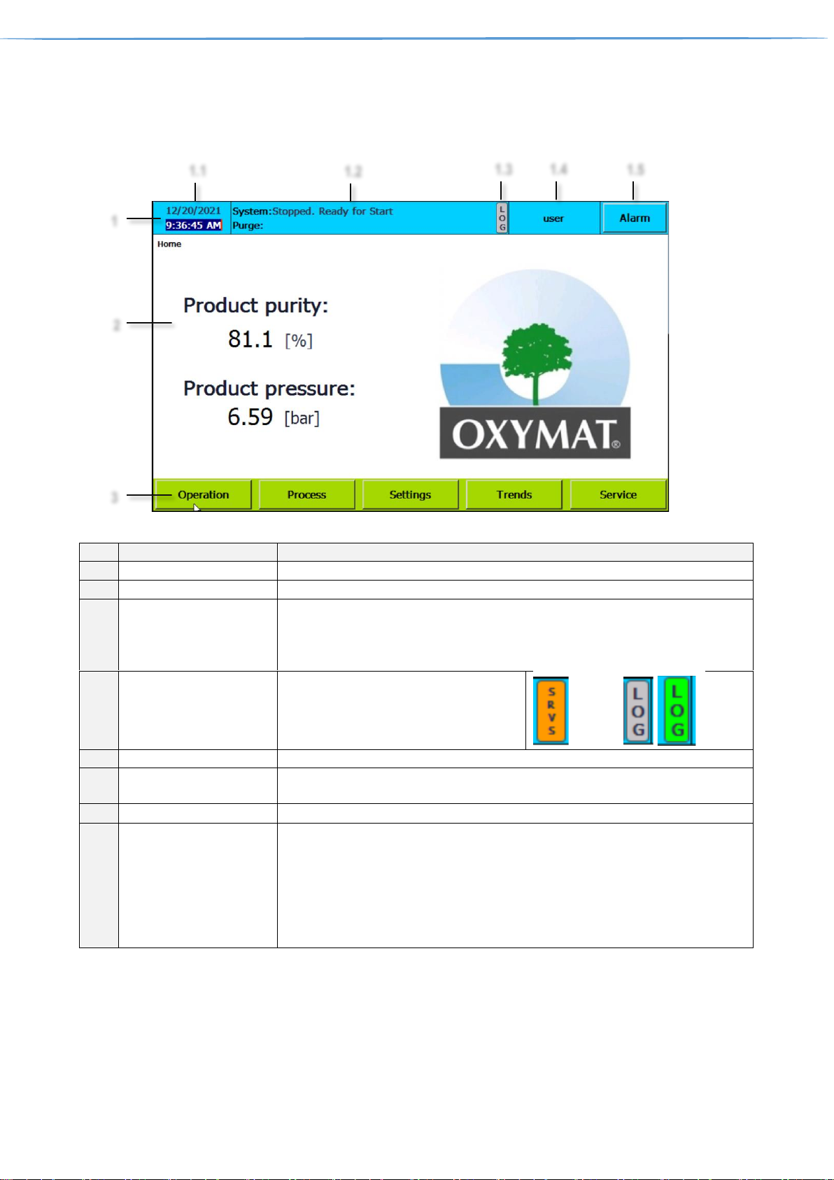
3. Home
The home screen is the screen that is shown automatically when the PSA Generator is powered up.
Ref.
Designation
Function
1
Information bar
1.1
Date & Time information
Shows screen time. Can be tapped to change time and date.
1.2
PSA status
PSA System and purge status information
PSA status information. It is divided into two sections, System and Purge, (Purge
is available only when Purity control addon is purchased)
See chapter 3.1 & 3.2
1.3
LOG/SRVS
Indicates when
Logging is inactive when grey
Logging is active when bright green
Service mode is active SRVS displayed
1.4
Log-in information
Shows information about user and can be tapped to change user.
1.5
PSA Alarm information
Blue = no active alarms, Flashing red = active alarm present,
Can be tapped to see active alarms and alarm history. See chapter 9. Alarms
2
Screen specific content
Specific for each screen, Home screen shows Product purity & pressure
3
Buttons bar
Accessible touch buttons (black text on green background),
Can be tapped to view specific screen.
Operation is described in Chapter 4
Process is described in Chapter 5
Settings is described in Chapter 6
Trends is described in Chapter 7
Service is described in Chapter 8
1
2 3 1.1
1.2
1.3
1.4
1.5
User & Superuser Manual intelliControl Siemens v.14.1.2022 Page 7 of 28
3.1. System status
Ref.
Status
Function
1
Stopped. Ready for start
Default state when PSA Generator is turned off and is ready for start
2
Stopped. Cannot Start
Default state when PSA Generator is turned off and cannot be started
because alarm (A and C alarm type) is present. See chapter Alarm 9.
For more details
3
Starting air pack
Air pack starting See chapter Process settings 6.2 Air pack control
4
Filling air tank
When PSA Generator is started compressor is filling air tank, when
setpoint is reached, starting sequence continues with ref. 5
5
Equalizing PSA columns
Equalizing pressure in PSA Generator columns
6
Running normally
PSA Generator running normally
7
Standby mode
PSA Generator is in standby mode. See chapter Advanced settings 6.5
Standby mode
8
Remote started – Running normally
PSA Generator running normally – started by remote digital input
9
Remote started – Standby mode
PSA Generator is in stand by mode – started by remote digital input
10
Stopping after PSA sequence
Stopping PSA Generator, manual stop or by Alarm (type C)
3.2. Purge status
For details about Purity control settings, see chapter 6.5 Advanced settings
Ref.
Status
Function
1
Purging
Purge valve is opened, delivery valve is closed.
2
Delivering
Delivery valve is opened, Purge valve is closed.
3
Waiting for min. pressure
Purity control is waiting for minimum pressure in product tank.
4
(No text)
Purity control addon is not purchased
User & Superuser Manual intelliControl Siemens v.14.1.2022 Page 8 of 28
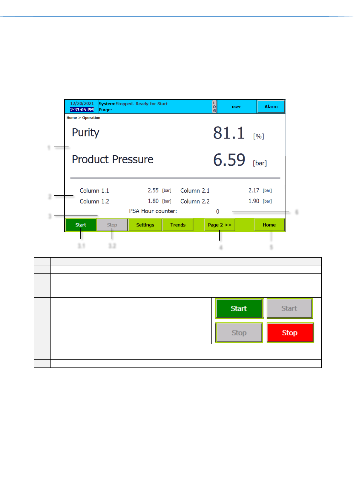
4. Operation
Tapping the operation button on home screen leads to operation where PSA starting and stopping is operated
When the PSA is powered up the first time or if there has been a power failure, the oxygen, nitrogen sensor will
need to heat up to measure correct. As long they are doing that, the readings can be incorrect (several seconds).
Ref.
Designation
Function
1
Product parameters
Shows information about purity & pressure in product tank
2
Column pressures
Shows information about pressure in both PSA generator columns. Respectively in four
if PSA Generator is X2 version.
3
PSA Start & Stop
Start & Stop of the PSA Generator
3.1
Start
Green when PSA is not running
Grey when PSA is running
Can be tapped to start
3.2
Stop
Grey when PSA is not running.
Red when PSA is running
Can be tapped to stop
4
Log-in information
Can be tapped to move to page 2 of Operation screen
5
Home
Can be tapped to return to Home screen
6
PSA Hour counter
PSA running hours counter
1
2
3.1 4 5
3.2
3
6
User & Superuser Manual intelliControl Siemens v.14.1.2022 Page 9 of 28
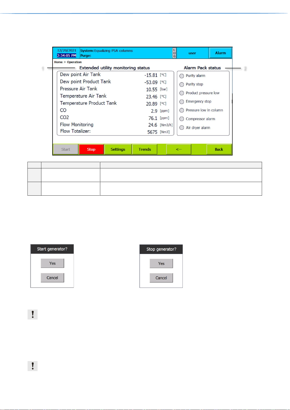
Page 2
Ref.
Designation
Function
1
Extended utility monitoring
status
Addon that extends monitoring to additional instruments
Visible only when extended utility monitoring addon is purchased
2
Alarm pack status
Addon that indicates alarms for customer
Visible only when alarm pack addon is purchased
4.1. PSA generator Start & Stop
It is possible to start the PSA when no critical or high level alarms are active. tap “Start” button to start PSA.
Small box appears with confirmation statement: „Start generator? “
To stop generator tap stop button. Again small box appears with confirmation statement: „ Stop generator? “. It
is not possible to restart during the stopping sequence. The text “Stopping” is shown on the Information bar.
Pop up screen when
starting PSA generator
Pop up screen when
stopping PSA generator
4.2. Start & Stop in service mode
Service mode is dedicated for service personnel & troubleshooting only.
It is possible to start the PSA in service mode when no critical alarms are active. Go to Settings/Advanced
(Chapter 6.5) and press “Service mode” ON.
To stop service mode, press button OFF. Than start/stop generator as is described above (Start generator).
It is not possible to restart during the stopping sequence (the text “Stopping”) is shown on the Information bar. It
is possible to switch service mode during running generator. To start service mode the operator must log in
as superuser.
Pressure stop/restart function, high and low alarms are bypassed in service mode.
1
2

User & Superuser Manual intelliControl Siemens v.14.1.2022 Page 10 of 28
5. Process
Tapping the Process button on home screen leads to Process screen where Process overview can be observed
including basic debugging information.
Ref.
Designation
Function
1
Debug information
Shows information about currently running process times
2
Reset totalizer
Can be tapped to reset flow totalizer
3
Test Drain
Can be tapped to test drain valve functionality located in the air tank
4
PSA Process information
Shows PSA1 column pressures and indicates opened valve with green dot
If PSA generator is X2 version, shows also PSA2
5
Product tank process information
Shows Product tank pressure
6
Back
Can be tapped to return back
1
2 3 6
5
4

User & Superuser Manual intelliControl Siemens v.14.1.2022 Page 11 of 28
6. Settings
Settings is the place where PSA Generator can be configured. It has lot of sub-screens, tapping the Settings
button on home screen leads to sub screen visited previously.
6.1. General settings
Ref.
Designation
Function
1
PSA Generator factory
information
Shows information about PSA Generator factory info such as model and serial
number, software version.
2
PLC Time information
Green Online indicates, that connection is established,
Offline button can be tapped to disconnect.
Red Offline indicates, that connection is not established.
Online button can be tapped to connect.
SET_PLC_time can be tapped to set PLC time to current
display time. To see more about screen time please refer
to Home screen.
3
Current PLC time/date
information
Shows information about current PLC time and date,
Note: PLC time/date can be different compared to screen time/date
1
2
3

User & Superuser Manual intelliControl Siemens v.14.1.2022 Page 12 of 28
6.2. Process settings
Ref.
Designation
Function
1
Process times Settings
The process time values are controlling the basic functionality of the PSA. Process
settings are pre-set during test generator by test engineer and only with permission
from Oxymat can be changed.
2
Air pack control
Shows information about Air pack. Can be tapped to enable/disable Air dryer or
compressor. (remote stop/start, run/alarm signal). Devices must be connected.
OFF- device is disabled
ON- device is enabled
2.1
Air pack delay
Shows information, about start delays for each device of Air pack. Can be tapped to
change start delay of Air compressor or Air dryer
3
Drain Settings
Shows drain valve settings, Can be tapped and changed.
4
Drain in Stop mode
Enable disable draining during Stop mode, Intervals can be chnaged
This example uses the drain valve operation with 3 min interval and 5 sec open time for drain valve.
The drain function always starts with an open period.
1
2
2.1
4
3
Drain open
Drain closed
Drain valve
5 s.
3 min

User & Superuser Manual intelliControl Siemens v.14.1.2022 Page 13 of 28
6.3. Measure 1 settings
Ref.
Designation
Function
1
Measurements
Shows list of basic measurements. Column 2.1 & 2.2 is only available for X2
PSA generator
2
Measurements range
Can be tapped to change Low and High range
3
Actual values
Shows actual value of the measurements
6.4. Measure 2 settings
Ref.
Designation
Function
1
Utility monitoring
Measurements
Shows List of measurements available only with utility monitoring addon.
Square can be tapped to disable measurement
Enabled measurement
Disabled measurement
2
Measurements range
Can be tapped to change Low and High range
3
Actual values
Shows actual value of the measurements
1
3
2
1 3 2

User & Superuser Manual intelliControl Siemens v.14.1.2022 Page 14 of 28
6.5. Advanced settings
Ref.
Designation
Function
1
Standby settings
Shows information about PSA Generator factory stand by settings. Can be tapped to
change stand by pressure, restart pressure and minimum cycles required before going
into standby.
When the pressure reaches the pressure stop level, then the PSA goes into stand-by
mode and wait for the pressure to drop below the pressure restart level. Then the PSA
will start again automatically. The standby mode will be cancelled if purge valve is opened.
2
Temporary
password
Temporary password can be inserted. With temporary password superuser is able to
enable purity control functionality (Ref. 3) or Enable/disable one of the PSA generators
X2 version only (Ref. 4). Contact Oxymat service for password.
Purity control
temporary enabler
Purity control is an addon and enable when
purchased. In case of purchase after delivery it can
be activated by temporary password. Upon inserting
temporary password, enabler is displayed
3
Purity control
settings
Can be tapped to change thresholds of purity control and minimum pressure required for
purity control functionality
PSA Oxygen generator
If the purity reading drops below the “Purge start” value and the pressure in the product
tank is above “Min Purge Pressure” then the purge function opens the purge valve and
closes the delivery valve.
The system automatically calculates the purity and pressure levels where the delivery
valve is opened again.
PSA Nitrogen generator
1
5
3
2
6
4
7
Time
Stop level
Restart level
Pressure in product vessel (P)
PSA running

User & Superuser Manual intelliControl Siemens v.14.1.2022 Page 15 of 28
If the purity reading exceeds the “Purge start” value and the pressure in the product tank
is above “Min Purge Pressure” then the purge function opens the purge valve and closes
the delivery valve.
4
X2 PSA Generator
temporary selector
Can be tapped to enable PSA1 or PSA2
5
AutoStart after
power failure
This feature allows the control to start automatically after power failure. When the power
is recovered, then a special “recover” sequence is started and the control will try to start
again.
6
Service mode
When no critical alarms are active, is possible to start the PSA in service mode. Consider
that the pressure stop/restart function, high and low alarms are bypassed in service mode
7
Stop runtime
Can be tapped to stop runtime and access Desktop and Start Center of the Siemens HMI.
It is used to access IP settings of the HMI or configuration of Remote control view. See
chapter 11 for more details
6.6. Alarm settings page 1 & 2
Ref.
Designation
Function
1
Alarm delay
At every startup alarms are not active for preset period of time. Can be tapped to
change.
2
Changeable Alarms
Complete list of changeable alarms is divided into two pages.
3
Alarm setpoints
Alarm setpoints are factory preset. Can be tapped to change these settings.
1
2
3

User & Superuser Manual intelliControl Siemens v.14.1.2022 Page 16 of 28
6.7. Smart delivery
Smart delivery is applicable only for PSA Oxygen Generators
Ref.
Designation
Function
1
Smart delivery settings
Smart delivery settings are preset by Oxymat. Adjustment is not possible.
The actual delivery clip time is calculated based on the actual pressure in the product
vessel. When the pressure is 0 (zero), then the minimum clip value is used.
When the pressure reaches the reference pressure (or above), then the maximum
value is used. In between 0 (zero) and the reference pressure, then the clip time is
calculated based on the linear function shown below.
2
Temporary password
When Logged as superuser and temporary password provided by Oxymat, smart
delivery can be disabled and altered. (Diagnostic purpose only)
1
2

User & Superuser Manual intelliControl Siemens v.14.1.2022 Page 17 of 28
6.8. PID Flowcontrol
Ref.
Designation
Function
1
PID controller status
Shows status of the PID controller. Automatic or Manual.
In Automatic mode, controller works according to the Flow setpoint with PID
parameters active
In Manual mode, the valve % open must be manually set. (See Ref. 3)
2
Flow setpoint
Shows setpoint of the Flow, can be tapped to change (Automatic mode only). Shows
also Flow input and % valve open.
3
PID parameters
proportional, integral, and derivative settings of the controller, Can be tapped to
change.
4
Manual mode
Can be tapped to switch between Manual and Automatic mode.
the valve % open can be set
5
PID reset
Reset Controller- clears error code
Restart Controller- restart of automatic mode for specific time
6
Error code
Diagnostic tool
1 3 4
5
2
6

User & Superuser Manual intelliControl Siemens v.14.1.2022 Page 18 of 28
6.9. SMS setting
Ref.
Designation
Function
1
SMS centre
SMS centre number of your provider, Can be tapped to insert
2
Alarm broadcast
Shows for how many numbers alarms are sent. Can be tapped to modify
3
Accepted SMS settings
Every change of the settings must be applied with this button.
4
Name/Phone
Shows information about names and phones. Can be tapped to insert up to 5 names
with numbers. recipients in the list can send SMS commands to intelliControl Siemens.
5
Test/Delete
Test –send test SMS to recipient
Delete – delete name/number
6
Send SMS status
sending text message
text message send
text message sending error
Before first using insert unlocked SIM card.
It is possible sends a text message containing alarm information to any cell phones, but extended with SMS
control. System can receive a text message containing control information.
Users in the user list are able to send SMS commands to intelliControl – Siemens:
Command
Explanation
#status#
The response from intelliControl – Siemens will be:
Product purity: xx.x
Product pressure: yy.y
System: zzzzzzzzzzzzzzzzzzzzzzzzz
xx.x will show actual O2 level
yy.y will show actual pressure in product vessel
zzzzzzzz shows the status text ex. Reast for start.
#start#
This command will try to start the system. Response will be “#start command executed”.
#stop#
This command will try to stop the system. Response will be “stop command executed”.
#reset#
This command will reset alarms. Response will be “#reset command executed”.
Example:. #status#(sender phone number)
1
2
3
5
4
6

User & Superuser Manual intelliControl Siemens v.14.1.2022 Page 19 of 28
7. Trends
Trends is the place where PSA Generator recent history parameters development can be viewed. It is divided
into six sub-screens. Availability of trends is limited to purchased instruments
Column pressure –pressure measurements in the PSA generator columns
Pressure inlet/Outlet – pressure measurements in the Air tank and Product tank
Purity – Oxygen content measurement in the Product tank
Temperature – temperature measurements in the Air tank and Product tank
Dew point - moisture measurements in the Air tank and Product tank
Flow - flow measurement of product
Ref.
Designation
Function
1
Auto changeable limits
for trend (Axis Y)
Units are according to the measurements screen. See chapters 6.3 & 6.4
2
Trend view
Can be tapped to stop trend curve view forward & backward or zoom in & out
3
Trend name
Trend(s) name and color designation
4
Actual trend
Actual trend view
5
Time (Axis X)
Time & date in actual view
1
2 3 5
4

User & Superuser Manual intelliControl Siemens v.14.1.2022 Page 20 of 28
8. Service
Service is the place where PSA Generator service inspection intervals can be viewed and reset
Ref.
Designation
Function
1
PSA service counter
Counter of running hours for PSA Generator maintenance
2
Filter service counter
Counter of running hours for Filter cartridge maintenance
3
Pre-set running hours
8000 hours for PSA Generator and 4000 hours for Filter is factory pre-set. Can be
tapped to change this value
4
Reset counter
Can be tapped to reset current service counters
Both service counters are descending from pre-set value to 0, and when it is reached, service maintenance is
required.
1
2
4
3
User & Superuser Manual intelliControl Siemens v.14.1.2022 Page 21 of 28
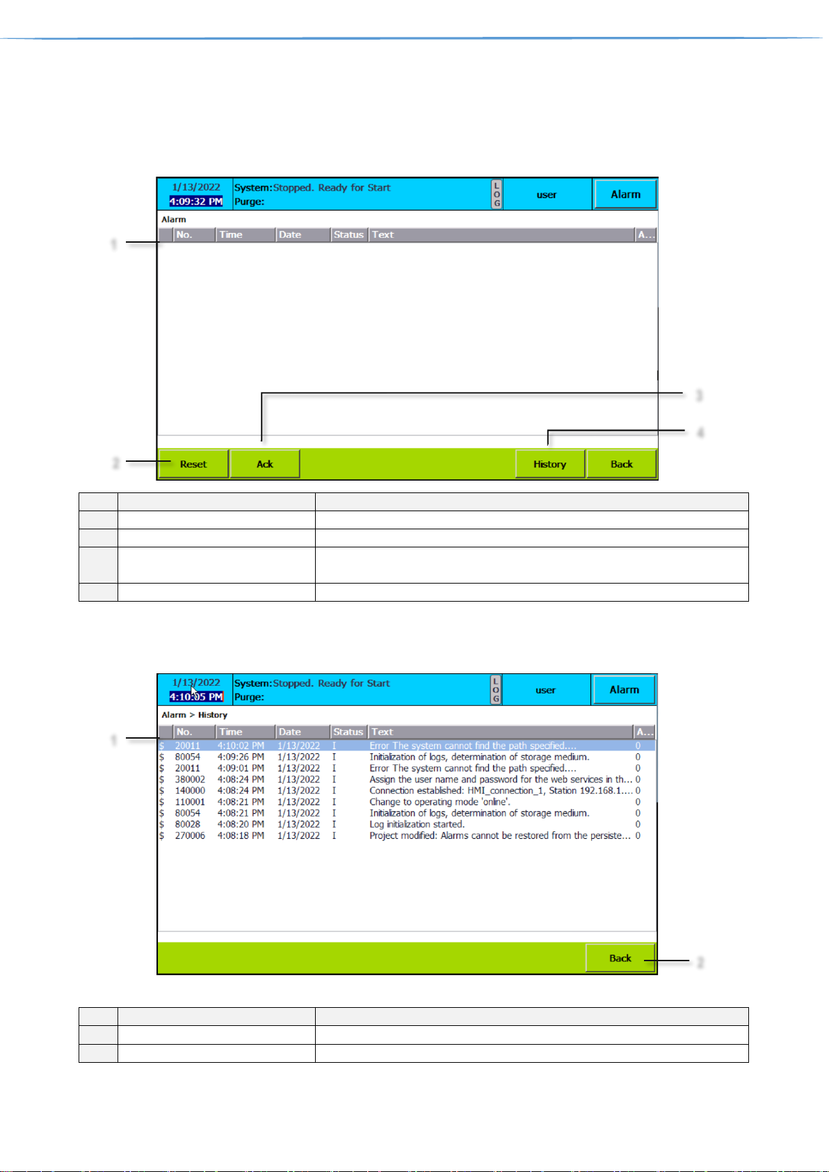
9. Alarm
Tapping the Alarm button on home screen leads to Active Alarms screen, where alarms can be reset,
acknowledged or history can be viewed.
Ref.
Designation
Function
1
List of active alarms
Shows active alarms, when occurred, with short text information
2
Reset
Can be tapped to reset alarm
3
Acknowledgement
Can be tapped to acknowledge alarm for which is acknowledgement needed
before reset
4
Alarm History
Can be tapped to see Alarm history screen (chapter 9.1)
9.1. Alarm history
Ref.
Designation
Function
1
Alarm history list
Shows history of alarms/events occurred
2
Back
Can be tapped to return
1
2
3
4
1
2

User & Superuser Manual intelliControl Siemens v.14.1.2022 Page 22 of 28
9.2. Alarm List & philosophy
The alarms are grouped into three categories. Quick stop alarms will stop the PSA immediately.
Delayed stop (with equalization of PSA or after PSA sequence) alarms will perform a controlled stop and
Indicative alarms does not affect the PSA sequence and can be considered as a message.
Alarm type: X,Y
A: Quick stop. (X)
B: Quick stop with equalization of PSA. (X)
C: Stop after PSA sequence. (X)
D: No stops only indicative. (X)
Y=1, Acknowledgment is required to reset the alarm. (Y)
Y=0, Acknowledgment is not required to reset the alarm. (Y)
Digital alarms
Broken Wire Alarms
Alarm Type
Alarm text
Alarm Type
Alarm text
A1
Emergency stop
C1
Product dew Point BWA
D0
Alarm on Compressor
C1
Air Tank dew Point BWA
D0
Alarm on Dryer
C1
Purity BWA
C1
UPS – Running on Battery
C1
CO BWA
D1
UPS - Alarm
C1
CO2 BWA
D0
PSA Filter Service required
C1
Product Pressure BWA
D0
PSA Filter Service Warning 1
C1
Flow Control BWA
D0
PSA Filter Service Warning 2
D1
Column 1.1 pressure BWA
D0
PSA Service required
D1
Column 1.2 pressure BWA
D0
PSA Service Warning 1
D1
Column 2.1 pressure BWA
D0
PSA Service Warning 2
D1
Column 2.2 pressure BWA
D0
Alarm on BEKO drain 1
D1
Air pressure BWA
D0
Not PSA selected in X2 Mode
D1
Air temperature BWA
D1
Start after Power Failure
D1
Product temperature BWA
Analogue Alarms
Alarm Type
Alarm text
Alarm Type
Alarm text
D1
Product Purity Alarm
D1
Air Tank Dew Point Alarm
C1
Product Purity Stop
C1
Air Tank Dew Point Stop
D1
Product Low Pressure Alarm
D1
Product Dew Point Alarm
C1
Product Low Pressure Stop
C1
Product Dew Point Stop
D0
Pressure Low Column 11
D1
Product Temperature Alarm
D0
Pressure Low Column 12
C1
Product Temperature Stop
D0
Pressure Low Column 21
D1
OverFlow
D0
Pressure Low Column 22
D1
CO Alarm
C1
Air Tank Pressure Low
C1
CO Stop
D0
Air Tank Pressure High
D1
CO2 Alarm
D1
Air Tank Temperature Alarm
C1
CO2 Stop
C1
Air Tank Temperature Stop

User & Superuser Manual intelliControl Siemens v.14.1.2022 Page 23 of 28
10. Access levels
Operator can log in anytime by tapping user information in information bar (see home screen for details). Or when tapping
a password protected item, a Login screen pops up. The Operator can enter the password.
As default 4 levels are implemented:
Level
login
password
Function
1
Guest / not logged
Monitor
2
user
4021
Monitor & Operate
3
superuser
182087
SuperOperate
4
developer
available only for Oxymat personnel
DeveloperOperate
Accessibility matrix, Some Functions are available only for certain PSA Generators or addons
Screen
Sub-screen
No user
logged in
USER
SUPERUSER
SUPERUSER +
TEMPORARY PASS
Monitor
Monitor
Operate
Super
Operate
Temporary
HOME
full access
full access
full access
N/A
OPERATION
full access
full access
full access
N/A
PROCESS
Test Drain
full access
full access
full access
N/A
Reset totalizer
View only
full access
full access
N/A
SETTINGS
General
Gen.settings
View only
View only
View only
N/A
PLC TIME
View only
View only
Full access
N/A
Process
Drain settings
View only
View only
Full access
N/A
Process times
View only
View only
View only
full access
Advan
ced
StandBy Settings
View only
full access
full access
N/A
Select PSA (X2
MODE)
View only
View only
full access
N/A
Autostart
Powerfailure
View only
full access
full access
N/A
Service Mode
View only
View only
full access
N/A
Purity Control
(Purge Function)
View only
ONLY:
Purge Start/Stop
Min. Purge pressure
Cannot enable/disable Purity control
full access
PILOT_control
View only
View only
full access
N/A
Alarm
View only
ONLY:
Purity Alarms,
Product Pressure
Alarms
full access
N/A
Measure 1
View only
View only
full access
N/A
Measure 2
View only
View only
full access
N/A
PID flow control
View only
View only
full access
N/A
SMS settings
View only
View only
full access
N/A
Smart delivery
View only
View only
View only
full access
SERVICE
View only
View only
full access
N/A
TRENDS
full access
full access
full access
N/A

User & Superuser Manual intelliControl Siemens v.14.1.2022 Page 24 of 28
11. HMI desktop and Start center
To access HMI desktop and Start Center runtime must be stopped.
In chapter 6.5 Advanced settings. Is described how to stop runtime.
Ref.
Designation
Function
1
Start
Can be tapped to Start HMI Runtime
2
Settings
Can be tapped to open Settings and configure IP adresses and
WinCC for remote view.
11.1. Remote view
Open “Settings”
Continue to “WinCC Internet Settings”
Proceed to “Remote” and then
1
2

User & Superuser Manual intelliControl Siemens v.14.1.2022 Page 25 of 28
Tap “Change settings”
Start automatically after booting must be enabled
Set two security levels:
Password 1 – control – remote control
Password 2 – view – remote view (click on View only)
After setting the passwords, return to the “HMI Desktop and Start center” and run „Runtime“. Having that done, the
application starts at the HMI. Set an identical IP address at your laptop as it was done at the HMI. Now you can start
the application „SmartClient“. A window opens, where a „password“ is required. We set in „settings“ for „Smart Server“
(see pic. 29) two levels:
1. Control
2. View
Choose „control“

User & Superuser Manual intelliControl Siemens v.14.1.2022 Page 26 of 28
An application is opened right away that is also running on the HMI. In the „control“ mode, full control of HMI is
enabled. It depends on the logged user_superuser.
In the „view“ mode, only the active screen on HMI is shown. In this mode, control is not enabled, screens cannot be
changed
11.2. IP address change
In case of IP change of the HMI, the IP address of the PLC needs to be altered as well.
Open “Settings”
Continue to “Network and dial-up connection“ and
continue to „PN_X1”
In PN_X1 Settings pop up window, “IP address” of the HMI can be changed, and in the case of having more networks
a “Default Gateway“ can be set as well.

User & Superuser Manual intelliControl Siemens v.14.1.2022 Page 27 of 28
12. Logging
Data logging is not availible for KTP700 BASIC HMI. To collect data, standard SD memory card can be used.
To correctly inserd memory card:
• Open the enclosure and refert to backside of the HMI panel.
• Unlock the slot by black slider lock to right side.
• Insert SD card into the DATA X51 slot
• Lock black slider lock to left side
Ref.
Designation
Function
1
HMI backside
N/A
2
Black slider lock
Slide to right to access SD card slot,
Slide to left to lock SD card lock
3
SD card slot
SD memory card can be inserted
2 3 1

User & Superuser Manual intelliControl Siemens v.14.1.2022 Page 28 of 28
13. Loading program from SD card
It is necessary to record parameters of all settings, because after project transfer from SD card all
pre-set parameters will be lost (ranges, alarm setting, Start – Stop pressure values, etc. )
Is available only when software backup is provided from Oxymat. Industrial Siemens SD card
must be used.
Industrial Siemens SD card must not be formatted by standard PC/Laptop
1. With the system switched off you slot the memory card into the memory card slot of the S7-1200 CPU.
2. Switch on the S7-1200 CPU. A flashing sequence between the "RUN/STOP", "ERROR" and "MAINT"
LEDs indicates that the program is currently being transferred to the controller. The end of the transfer is
indicated by the "RUN/STOP" LED lighting orange and the "MAINT" LED flashing at the same time.
3. Switch off the S7-1200 CPU and remove the memory card from the slot.
4. Then switch on the S7-1200 CPU again. The application then starts up automatically ("RUN/STOP" LED
lights green).
5. After restart of CPU please re-enter recorded parameters to system.
Ref.
Designation
Function
1
CPU
CPU identification
2
Cover
Protective cover of terminals and SD card slot. Can be opened to access SD card slot
3
LED indicators
Indicates status of the CPU
4
SD card slot
SD card can be inserted. Accepts only Siemens SD cards
2
3
4
1
 Loading...