

Page 1
INSTALLATION AND OPERATION MANUAL
Heat Recovery Unit OXYGEN X-Air C200
Rev 1.6 2019.06
Page 2

1
Page 3

CONTENTS
1. TRANSPORTATION AND STORAGE OF EQUIPEMENT .......................................................................................3
2. UNIT PACKAGE ..................................................................................................................................................4
3. SAFETY REQUIREMENTS ...................................................................................................................................5
4. EU DECLARATION OF CONFORMITY .................................................................................................................6
5. TECHNICAL DATA ..............................................................................................................................................7
5.1. Performance characteristics .................................................................................................................8
5.2. Performance and power consumption .................................................................................................8
5.3. Sound characteristics ............................................................................................................................9
5.4. Dimensions and weight ..................................................................................................................... 10
6. FUNCTIONALITY ............................................................................................................................................. 11
7. INSTALLATION OF THE UNIT .......................................................................................................................... 12
7.1. Selecting the mounting location ........................................................................................................ 12
7.2. Installation incline ............................................................................................................................. 12
7.3. Connecting ducts ............................................................................................................................... 13
7.4. Installing the maintenance and servicing hatch ................................................................................ 14
7.5. Connecting the condensate drain ..................................................................................................... 15
8. CONNECTION OF THE UNIT ........................................................................................................................... 16
8.1. Connecting electric circuit ................................................................................................................. 16
8.2. Connecting the control panel ............................................................................................................ 17
8.3. Connector of comfort functions ........................................................................................................ 18
8.4. Control board electrical wiring diagram ............................................................................................ 19
8.5. Description of control board contacts ............................................................................................... 20
9. OPERATION OF THE UNIT .............................................................................................................................. 21
9.1. Control panel with a knob ................................................................................................................. 21
9.1.1. Operating state indicator .............................................................................................................. 21
9.1.2. Air filter replacing / anti-frost protection indicator ...................................................................... 21
9.1.3. Failure indicator ............................................................................................................................. 22
9.1.4. Additional system settings............................................................................................................. 23
9.2. Control panel with touchscreen display ............................................................................................ 25
9.2.1. Standby mode ................................................................................................................................ 25
9.2.2. Main screen ................................................................................................................................... 26
9.2.3. Settings menu ................................................................................................................................ 27
9.2.4. Setting up weekly operation program ........................................................................................... 27
9.2.5. Failure indication ........................................................................................................................... 28
9.3. Replacing of air filters ........................................................................................................................ 29
10. MAINTEINANCE AND WARRANTY ................................................................................................................. 31
11. CONTACTS ...................................................................................................................................................... 32
2
Page 4

1. TRANSPORTATION AND STORAGE OF EQUIPEMENT
Heat Recovery Unit (hereinafter – the Unit) is prepared for transportation and storage. Packaging
materials ensure protection against exposure to environment, dust and humidity. The Unit must be
properly secured during transportation to protect it against possible housing deformation or other
mechanical damage.
Transportation conditions:
Long-term storage conditions:
IMPORTANT! Sender does not assume any obligations towards damage or loss of the Unit or its part, if
there is no a corresponding record in the consignment document!
CONSIGNMENT ACCEPTANCE:
Carefully check the received consignment – make sure that the number of packages matches with
the consignment documentation. Upon noticing any non-conformity or damage of the package
(tears, dents or compressed box, detached or reattached packaging tape), inform the courier
immediately and indicate the disrepancies or damages in the consignment document.
Verify if the right product was delivered. Upon noticing any non-conformity, inform the Sender
immediately.
Verify if all the supplementary parts listed were delivered. In case of any doubt, contact the Sender
-20oC - +40oC.
+5oC - +40oC, relative air humidity <= 60%.
immediately.
Do not attempt to repair the Unit, damaged during the transportation by yourself!
3
Page 5
2. UNIT PACKAGE
Heat Recovery Unit Oxygen X-Air C200 1 pc.
Control panel 1 pc.
Contol panel connection cable, 10m 1 pc.
Fastening elements:
L-shaped horizontal installation bracket 4 pcs.
Bolt (type M5), 8 mm 8 pcs.
Spring washer (type M5) 8 pcs.
Condensate drain nozzle, Ø32 1 pc.
Condensate drain gasket, Ø20 1 pc.
Installation manual 1 pc.
4
Page 6

3. SAFETY REQUIREMENTS
Carefully read and follow safety requirements provided below before installing and while operating the
Unit:
Do not discard the Installation and operation manual, keep it for future reference.
The Unit should be installed and operated in compliance with this Installation and operation
manual, following the requirements of effective legislation and standards.
When connecting the Unit to mains supply, grounding must be installed in compliance with
requirements of effective legislation and standards.
To prevent accidents and potential damage to the Unit, it should be installed, connected,
maintained and repaired only by qualified technician. Never attempt to do this by yourself!
Turn off the Unit by using Control panel and wait for fans to stop completely before replacing air
filters.
Turn off the Unit by using Control panel, wait for fans to stop completely and disconnect the Unit
from mains supply before performing any maintenance.
Before connecting the Unit make sure that no items will get sucked into the its air intake openings!
Children may only use the Unit under adult supervision.
The Unit is not intended to be used by persons (including children) with reduced physical, sensory
or mental capabilities, unless they have been instructed to use of the Unit and under constant
supervision of person held responsible for their safety.
Only original supplementary parts and consumables, certified by manufacturer should be used.
The Unit package (cardboard, plastic, foam polystyrene) can pose hazard to children. Dispose of
or recycle the package elements!
Disused Unit should be disposed of in accordance with requirements of legislation on handling
of waste electrical and electronic equipment.
IT IS PROHIBITED to operate the Unit with damaged mains supply cable! Switch off the power
circuit-breaker to disconnect mains supply and contact a qualified technician or manufacturer
service centre immediately upon noticing such damage.
IT IS PROHIBITED to attempt the repair of the damaged Unit or its part, to open its cover! Contact
a qualified technician or manufacturer service centre.
5
Page 7

4. EU DECLARATION OF CONFORMITY
We, undersigned below, representing the manufacturer of ventilation equipment:
Sviezias oras, JSC
Birzelio 23-osios g. 23G
50220 Kaunas
LITHUANIA
confirm, that heat recovery ventilation device Oxygen X-Air C200 conforms to Europe Union standarts,
directives and regulations:
2009/125/EC – eco-design requirements for energy-related products
ES 1253/2014
2010/30/EU – labelling and standard product information of the consumption of energy and other
resources by energy-related products
ES 1254/2014
2011/65/EU – restriction of the use of certain hazardous substances in electrical and electronic
equipment (RoHS)
EN 50581(2012)
2014/35/EU – harmonization of the laws of the Member States relating to the making available on the
market of electrical equipment designed for use within certain voltage limits
LST EN 60335-1:2012 (EN 60335-1:2012)
LST EN 60335-1:2012/A11:2014
CEO Zilvinas Salialionis
10.05.2018, Vilnius
6
Page 8
5. TECHNICAL DATA
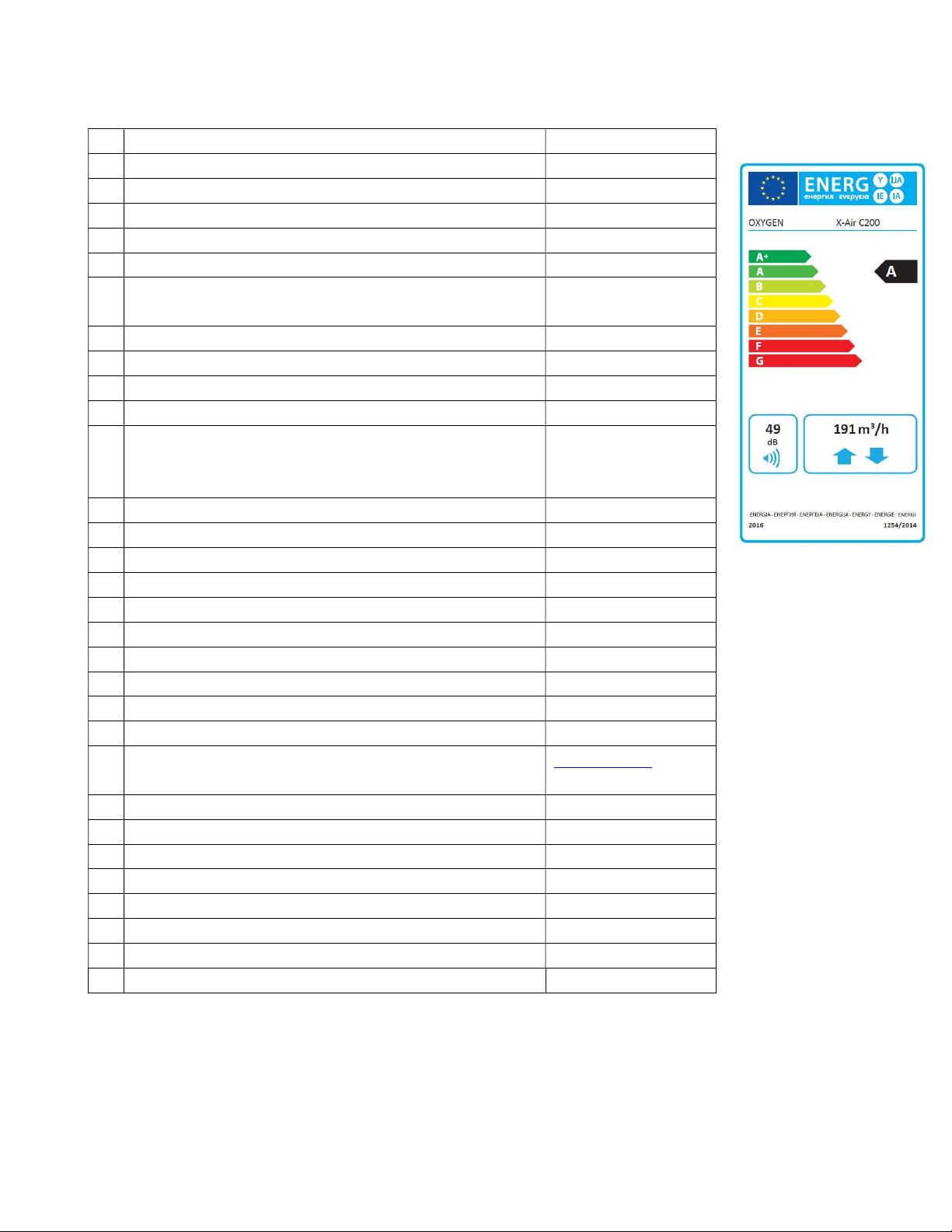
a) Supplier's name or trade mark OXYGEN
b) Model identifier X-Air C200
c) Specific energy consumption (SEC), SEC class A
Warm climate kWh/m2.a -15.7
Average climate kWh/m2.a -40.0
Cold climate kWh/m2.a -77.7
d) Declared typology Bi-directional,
residential ventilation
e) Type of drive installed or intended to be installed Variable speed drive
f) Type of heat recovery system Recuperative
g) Thermal efficiency of heat recovery % 81
h) Maximum flow rate m3/h 191
i) Electric power input of the fan drive, including
any motor control equipment, at maximum flow
rate
j) Sound power level (LWA) 49
k) Reference flow rate m3/s 0.0378
l) Reference pressure difference Pa 50
m) Specific power input (SPI) W/(m3/h) 0.353
n) Control factor 0.65
Control typology Local demand control
o) Declared maximum leakage rate:
internal % 2.31
external % 1.16
q) Position and description of visual filter warning See user’s manual
s) Internet address for pre-/dis-assembly
instructions
v) The annual electricity consumption (AEC)
Warm climate kWh/m2.a 1.9
Average climate kWh/m2.a 2.3
Cold climate kWh/m2.a 7.7
w) The annual heating saved (AHS)
Warm climate kWh/a 20.4
Average climate kWh/a 45.0
Cold climate kWh/a 88.0
W 106
www.oxygen.lt
According to commission delegated regulation (EU) No. 1254/2014
7
Page 9
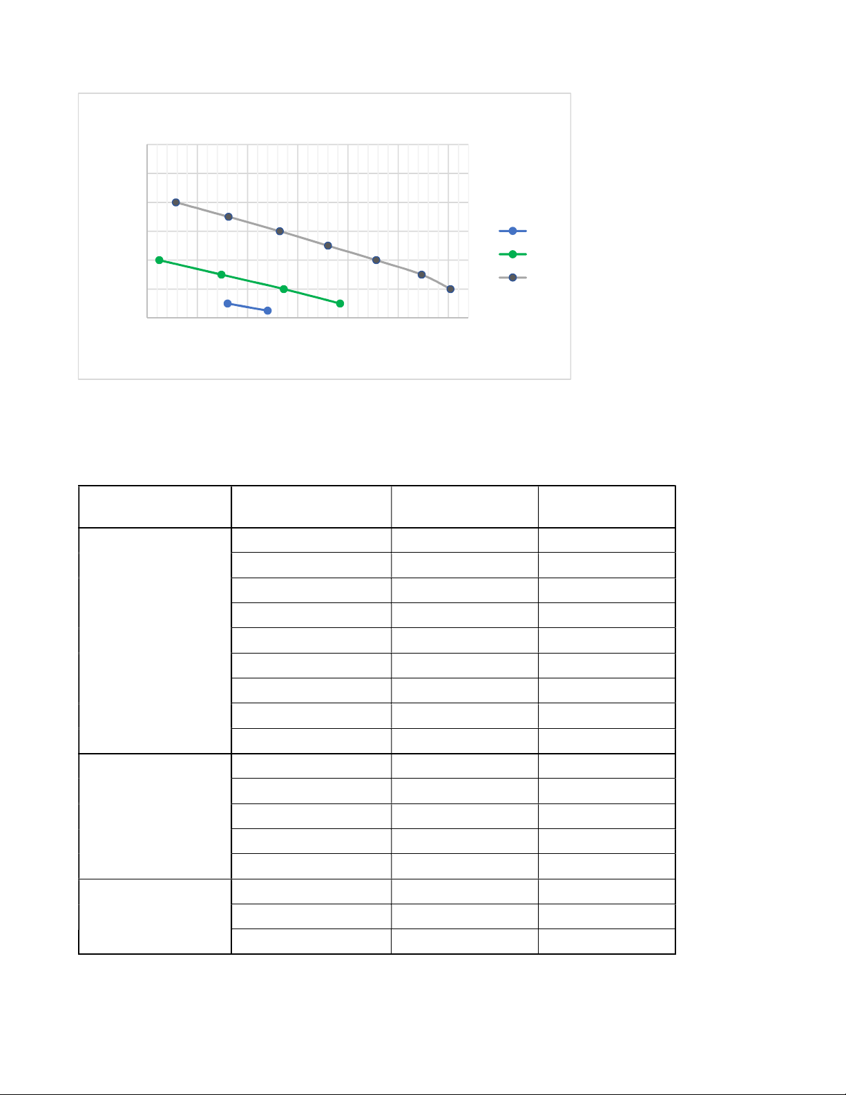
5.1. Performance characteristics
Performance curves
600
500
400
300
200
Pasipriešinimas, Pa
100
0
40 65 90 115 140 165 190
50%
70%
100%
Air flow, m3/h
Graph. 1. Ventilation power dependence on the resistance of the installed ventilation system
5.2. Performance and power consumption
Power setting Resistance, Pa Air flow, m3/h El. outlay, W
100 191 101
150 189 99
200 184 98
250 172 100
100%
300 154 98
350 136 96
400 110 97
450 91 97
490 75 98
50 140 46
100 130 46
70%
150 114 44
200 85 44
250 61 41
25 100 24
50%
75 80 24
115 50 22
According to EN13141-7, with G4 class filters installed.
8
Page 10
5.3. Sound characteristics
Power
Air duct
setting
125 250 500 1000 2000 4000 8000
Suppply 34.1 42.8 42.2 41.7 40.9 30.6 17.5 48.2
50%
Extract 13.3 35.6 35 26.8 22.4 14.8 12.6 38.8
Outside 15.1 36.7 32.1 26.9 21.8 14.4 12.6 38.5
Exhaust 28.9 39.7 42 40.7 38.5 28.6 16 46.6
Suppply 39 51.1 51.8 51.2 49.9 43.8 30.4 57.3
70%
Extract 21.5 45.2 44.5 36.6 33.2 22.5 14.2 48.4
Outside 22 44.6 42.8 36.1 33.1 21.7 13.7 47.3
Exhaust 35.4 51.1 51.6 50.4 48.4 41.8 28.7 56.8
Suppply 43 56.1 63.3 58.5 58.7 53.6 41.3 66.3
100%
Extract 30.1 47.7 55.3 46.5 42.4 32.1 21.6 56.7
Outside 29.7 48.1 54.3 45.7 42.4 30.7 20.7 55.9
Exhaust 41.2 53.3 62 58.4 57.6 52.7 40 65.2
According to LST EN13141-7.
Sound power level (LWA)
Octave band, Hz
Total
9
Page 11

5.4. Dimensions and weight
OXYGEN X
-
Air C200
–
left-side version
OXYGEN
X-Air C200
–
right
-
side version
Figure 1. Unit dimensions
Body dimensions and weight Length, mm Width, mm Height, mm Weight, kg
OXYGEN X-Air C200 1010 500 254 23
10
Page 12

6. FUNCTIONALITY
Function Control
panel with
a rotary
Ventilation
Silent and efficient EC fans
Stepless power setting adjustment 30-100%
Power setting at 5% steps within 30-100% range
Weekly operation program, up to 4 different modes for every week day
Ventilation boost activation by control panel button
System balancing by adjusting power of each fan
Constant air pressure maintenance
Display of outdoor, supply, extract and exhaust air temperatures
Display of relative air humidity indoors
Display of date and time
Stepless increase of preheater power
„WC boost″ activation by turning the light switch on
„Away″ - reduced ventilation power, when the security system is active
Adjustment of ventilation power according to CO2 level indoors *
Adjustment of ventilation power according to humidity level indoors *
Summer time ventilation – heat exchanger bypass device
Filtration
G4 class filter (average deposition of synthetic dust <90%)
M5 class filter (efficiency to filter 0.4 µm diameter particles 40-60%)
F7 class filter (efficiency to filter 0.4 µm diameter particles 80-90%)
Visual warning of the necessity to replace the filters
Filter lifetime metering
Filter fouling metering
Protection functions
Overheat protection
Anti-frost protection
Ventilation shutdown function upon activation of fire alarm
Visual warning of the Unit failure
Additional functions / features
Possibility to install according to the layout of outdoor ventilation openings
(right / left versions)
switch
Control
panel with
a LCD
*
*
* sensors for pressure maintenance and determination of indoor air quality are optional.
11
Page 13

7. INSTALLATION OF THE UNIT
7.1. Selecting the mounting location
It is recommended to install the Unit in a heated room such as bath, storage room, boiler room or an
attic. Make sure, that there is sufficient space to install not only the Unit itself, but also auxiliary ventilation
system components – noise silencers or air distribution boxes. Make sure that there is a possibility to
connect the condensate drain pipe of the Unit to the internal or external sewerage system.
Operating conditions:
The Unit should be installed horizontally, with servicing cover looking downwards. 4 L-shape fastening
brackets (provided) should be used to fasten Unit to the ceiling. Use ceiling pins or locking sleeves (not
included), depending on installation surface. It is essential to use vibroinsulation gaskets (not included)
to ensure that Unit vibration will not be transferred to the mounting surface.
+10oC - +30oC, relative air humidity <= 60%.
7.2. Installation incline
IMPORTANT! After Unit installation, make sure that the condensate drain corner is positioned lower than
remaining Unit corners (refer to Figure 2). This will ensure smooth removal of accumulated condensate.
Corresponding distances must be maintained from ceiling plane, when installing the Unit:
No. Distance from horizontal plane
1 20 mm
2 10 mm
3 0 mm
4 10 mm
12
Page 14

OXYGEN X
-
Air C200
–
left-side version
OXYGEN X
-
Air C200
–
right
-
side version
Figure 2. Horizontal installation diagram
7.3. Connecting ducts
It is recommended to install outside air supply and exhaust ducts as far as possible from each other to
prevent the ingress of contaminated air back to premises. Please refer to local construction regulations.
Make sure that outdoor humidity or precipitation will not get into the Unit, when connecting outside air
supply and exhaust ducts. Make sure that openings in the outside wall are installed lower than the Unit
itself. The air intake opening in the outside wall should be protected against precipitation ingress to
ventilation duct by grille or roof, with mesh to prevent ingress of insects and other small objects.
Figure 3. Air intake duct connection diagram
IMPORTANT! At least 1° ventilation duct incline should be ensured to prevent ingress of outdoor
humidity or precipitation into the Unit.
13
Page 15

IMPORTANT! Both outside air intake and exhaust ducts should be covered with a layer of thermal
insulation of sufficient thickness to prevent condensation of humidity on their walls due to different
outdoor and indoor air temperatures.
7.4. Installing the maintenance and servicing hatch
When installing the Unit ensure enough space for its maintenance. Suspended ceiling in the room should
be installed at least 40 mm from the lowest point of the Unit housing (refer to section 8.2. Installation
incline).
Maintenance and servicing hatch installed in the ceiling should be of suitable size to allow convenient
access to all Unit components. At least 100 mm distance should be ensured from every edge of the Unit.
Figure 4. Installation of maintenance and servicing hatch
IMPORTANT! Owner of the Unit shall ensure the possibility to perform Unit maintenance. If there is not
enough space for Unit maintenance, the manufacturer’s representative is entitled to refuse to perform
maintenance or repairs.
14
Page 16

7.5. Connecting the condensate drain
The Unit condensate drain should be connected to indoor or outdoor wastewater network. If condensate
drain is installed in non-heated premises or directed outdoors, it must be thermally insulated or equipped
with electric heater.
Install a round rubber gasket into the condensate drain socket, then firmly screw the condensate drain
nozzle in by hand.
Figure 5. Installing the condensate drain
IMPORTANT! Do not use pliers or other similar tools, as excess power applied may damage the unit.
The necessary incline of the condensate drain should be ensured during the installation: at least 2° incline
should be ensured in the horizontal part of the system.
Siphon is the obligatory part of the condensate drain system. It is recommended to use HL138 or similar
type, internally or externally mounted siphon with mechanical odor control damper. Siphon should be
installed according to the diagram “Connecting the condensate drain″, ensuring that the manufacturer
instructions on the incline, distances, necessary inspection hatch for the selected siphon model are
observed.
Figure 6. Connecting the condensate drain
15
Page 17

8. CONNECTION OF THE UNIT
- Comfort
f
unctions
c
onnector
(RJ-45) - Mains c
able
(
230V, 3x1.5mm
2
L+N+PE
)
Mains supply, control panel cable and, if necessary, comfort function connector should be connected to
the Unit, according to the following diagram:
- Control panel connector (USB)
Figure 7. Unit connection
IT IS PROHIBITED to connect any cables or devices to the connectors of the control panel and comfort
functions, despite similarity to any standard connectors. External similarity of connectors does not
guarantee compatibility – the connected devices may fail or damage the Unit. The failure of the Unit due
to incompatible supplementary parts connection will void the warranty!
8.1. Connecting electric circuit
WARNING!!!
To prevent accidents and potential damage to the Unit, it can only be connected by a qualified
technician. Do not attempt to do that by yourself!
Mains supply power rating shall comply with the rating indicated in the Unit manual.
Mains supply should be disconnected when connecting the Unit.
The Unit should be connected according to diagram provided in the User Manual.
Only power cable provided with the Unit should be used to connect it to power source.
Grounding should be installed in compliance with the requirements of effective legislation and
standards when connecting the Unit to mains supply.
Electric circuit must be equipped with suitable power circuit-breaker.
16
Page 18

Power supply 230V, 50Hz, 5A
Maximum electric power consumption – fans 106W
Maximum electric power consumption – preheater 500W
IP protection class 20
8.2. Connecting the control panel
It is recommended to install the control panel in residential premises (e.g., corridor or lounge) for
convenient access. It is recommended to install the control panel at 1.5 – 1.6 m height from the floor.
Figure 8. Control panel installation
IT IS PROHIBITED to install control panel in a premises, where relative air humidity exceeds 90%.
17
Page 19

8.3. Connector of comfort functions
The Oxygen X-Air C200 device supports the following external functionality:
Fire alarm – emergency shutdown of the Unit upon activation of fire alarm;
WC boost – ventilation boost activation upon switching on the light in the bathroom;
CO2 sensor – ventilation power increase based on readings of auxiliary CO2 or humidity
sensors connected;
Away – reduction of ventilation power when no one is at home. Requires security system to
be installed in the premises.
Functions can be activated by short circuiting the respective digital contacts of RJ45 function connector.
Conn. contact No. Function of ventilation system
1-2 Fire alarm
3-4 WC boost
5-6 CO2 / humidity sensors
7-8 Away
Figure 9. Contacts of functions connector
IMPORTANT! Only passive jumpers or electric relays should be used to activate the function!
IT IS PROHIBITED to connect the functions connector directly to electrical wiring network!
The optional RJ45 adapter can be used for more convenient connection:
Figure 10. Comfort functions RJ45 connector adapter
18
Page 20

8.4. Control board electrical wiring diagram
Figure 11. Control board electrical wiring diagram
IMPORTANT! Make sure that the Unit is disconnected from mains supply before connecting or
disconnecting system components.
19
Page 21

8.5. Description of control board contacts
AO1 Exhaust fan control 0-10V
GND Not used
AO0 Supply fan control 0-10V
GND Not used
X13 Exhaust air temperature sensor
X14 Supply air temperature sensor
X15 Outside air temperature sensor
X16 Inside air temperature/ humidity sensor
AI1 DI2 function – „Away″
GND
AI0 DI3 function – „CO2 sensor″
24V Not used
DI1 DI1 function – „WC boost″
GND
DI0 DI0 function – „Fire alarm″
GND
Tach1 Exhaust fan tacho signal
GND
Tach0 Supply fan tacho signal
GND
X20 Control Panel connector
X1 Exthaust air fan L
X3 Exthaust and Supply fans N
X7 Preheater L
X10 Supply fan L
X11 Preheater N
K1 Bypass N
K2 Not used
L Bypass L
L Mains L
N Mains N
N Not used
F1 315mA fuse
20
Page 22

- Ventilation power setting control knob
Operating state
- Air f
ilter replac
ing indicator
- Failure indicator
-
9. OPERATION OF THE UNIT
9.1. Control panel with a knob
Control panel with a knob makes it possible to gradually control the ventilation power. Colored LEDs
indicate status of the Unit.
Figure 12. Control panel with a knob
9.1.1. Operating state indicator
Flashing green led indicates that the Unit is connected to power supply:
flashes 1 time ventilation is off
flashes 2 times ventilation is on
flashes 3 times the Unit is shutting down, shutdown programs are being executed
9.1.2. Air filter replacing / anti-frost protection indicator
Flashing yellow led indicates:
flashing consistently it is necessary to replace filters
yellow and green leds flash in turns anti-frost protection is on
21
Page 23

Control panel will indicate the necessity to replace filters after 6 months of uninterruptable Unit operation
by consistent flashing of yellow led. Disconnection of the Unit from mains supply does not reset the
counter.
IMPORTANT! Filters may need to be replaced more frequently – refer to section 11.1. Replacing of air
filters for more information.
Green and yellow leds flashing in turns indicate that anti-frost protection has been activated – the
preheater is on.
IMPORTANT! Higher than usually power consumption is to be expected when the Unit is operating in
this mode.
9.1.3. Failure indicator
The flashing red led indicates that failure of the Unit component was detected:
flashes 1 time failure of outside air temperature sensor
flashes 2 times failure of exhaust air temperature sensor
flashes 3 times failure of supply air temperature sensor
flashes 4 times failure of extract air temperature sensor
flashes 5 times failure of supply fan motor
flashes 6 times failure of exhaust fan motor
flashes 7 times fire alarm has been activated
flashes 8 times failure of preheater
Unit operation will stop after detecting component failure. You can restart the Unit by following RESET
procedure:
RESET – gently press the hidden button S1 with thin screwdriver (safety-match, toothpick) through the
hole on the side of control panel two times, until all three color leds switch on. Then immediately press
and hold S1 button again for about 3 seconds, until all leds switch off.
22
Page 24

- R
eset button
S1
Figure 13. Reset button
IMPORTANT! If red failure indicator led starts flashing again after the Unit reset procedure has been
performed, contact manufacturer of the Unit or its local representative.
If both red and yellow leds are on (no flashing) – connection between control panel and the Unit was lost,
the Unit is operating in safe mode. Try switching off the power circuit-breaker to disconnect mains supply
and then switch it back again. If the problem persists, contact manufacturer of the Unit or its local
representative.
9.1.4. Additional system settings
Control panel is programmed to maintain 20 °C supply air temperature. Bypass function will be activated,
when there is no need to use heat exchanger, by evaluating outdoor and indoor temperatures.
Controllers for additional settings of ventilation system are installed on the back side of control panel:
P1 boost mode time setting
P2 boost mode power setting
P3 supply fan power adjustment
P4 exhaust fan power adjustment
S1 reset button
S2 not used
23
Page 25

Figure 14. Additional settings for control panel with a knob
You may get access to enhanced Unit functionality, by purchasing control panel with touchscreen display.
24
Page 26

9.2. Control panel with touchscreen display
Control panel with touchscreen display screen makes it possible to use the enhanced Unit functionality.
Figure 15. Control panel with touchscreen display
9.2.1. Standby mode
Touchscreen display of control panel will only display the time of day in standby mode if the Unit is
switched off. If the Unit is in operation, settings of preferred temperature and ventilation power will also
be displayed.
Figure 16. Control panel with touchscreen display in standby mode: the Unit is switched off, the Unit is in operation
25
Page 27

9.2.2. Main screen
TIme
Date
Outside air temperature
Extract filter lifetime
Supply air temperature
ON / OFF button
Settings menu
Ventilation boost button
Figure 17. Main screen of control panel with touchscreen display
Main screen displays:
Time of day
Date
Temperatures:
Preheater state indicator
Supply air filter lifetime
Exhaust air temperature
Exhaust fan state
Preferred room temperature
Preferred ventilation intensity
Bypass valve state
Extract air temperature and relative humidity
Supply fan state
o Outside air (refer to section on winter mode)
o Extract air (inside)
o Supply air
o Exhaust air
Relative humidity of indoor air
Lifetime of outside and extract air filters
Bypass valve state
Preheater state
This menu enables to:
Activate the “boost” mode by single touch of BOOST button
Access the settings menu
Set the preferred supply air temperature
Select the preferred ventilation intensity
26
Page 28

9.2.3. Settings menu
activation
Language
selection: LT, EN, RU, PL
Desired ventilation intensity
Preferred indoor air temperature
Date and time setting
Figure 18. Settings menu
Control panel settings menu enables to:
Set the system date and time
Select the menu language: English, Russian, Polish, Lithuanian
Set up weekly operation program
Set the duration of boost mode
Reset the filter lifetime counters – after replacing of air filters
9.2.4. Setting up weekly operation program
Weekly program settings, program
Boost mode settings
Filter lifetime counter reset
Up to 4 different ventilation modes can be set for each day of week. After selecting the week day, set:
operating mode start time
selected ventilation intensity
preferred supply air temperature
Day of the week
Operating mode start time
Figure 19. Weekly operating mode settings menu
27
Page 29

Weekly program will be saved by clicking “Back” button.
IMPORTANT! Click on the round button next to schedule button in main menu to activate a weekly
program. Green color of button means the program is active.
9.2.5. Failure indication
In case of Unit component failure, the RESET button will appear in main menu. Failed component will turn
red, the Unit operation will stop.
RESET button
Failed component
Figure 20. Failure indication
Press the RESET button. The Unit will restart and if the failure was resolved, will continue to operate. If
the problem with failed component will persist after the Unit reset procedure has been performed and
RESET button will reappear, contact manufacturer of the Unit or its local representative.
28
Page 30

9.3. Replacing of air filters
OXYGEN X
-
Air C200
–
left-side version
OXYGEN X
-
Air C200
–
right
-
side version
Outside air filter
Extract air filter
Extract air filter
Heat Recovery Unit Oxygen X-Air C200 is equipped with outside and extract air filters.
Outside air filter ensures supply air quality, protects against ingress of outdoor dust and insects
(G4, G4 Carbon, M5, F7 filtering classes);
Extract air filter protects the device against ingress of indoor dust and insects (G4 filtration class).
Figure 21. Locating air filters
Air filter replacing frequency depends on the selected filtering class and environment, where the Unit is
being operated. Dusty operation environment will foul filters faster.
Replacing of air filters:
Shut down the Unit by control panel, make sure that fans have completely stopped
Open the lid of the filter, that you intend to change, marked by „OXYGEN″ by firmly gripping it
and pulling out
Use fabric handle to remove a filter
Insert a new filter, following ventilation flow direction indicated on filter frame – it should point
towards center of the Unit
29
Firmly push the lid of the filter back to its place. Make sure it was tightly inserted into the Unit
housing
Page 31

It is recommended to replace air filters at least:
Filtering class
EN 779:2012
G4 Coarse 65% every 6 months
G4 Carbon ePM
M5 ePM10 55% every 4 months
F7 ePM1 70% every 2 months
Filtering class
ISO 16890
60% every 4 months
2.5
Recommended replacing frequency
IMPORTANT! The fouled air filters can result in ventilation power decrease and higher than usually power
consumption.
IMPORTANT! Only original, manufacturer recommended filters should be used. The use of low quality
third party filters can result in damage to sensitive device components due to excess dust or humidity.
Failure of the Unit caused by the use of non-original components, will void the warranty.
Replacement filters can be ordered at: www.oxygen.lt.
30
Page 32

10. MAINTEINANCE AND WARRANTY
Heat recovery Unit Oxygen X-Air C200 is granted 24 months warranty. Make sure to have the section
below properly filled in to confirm the installation date. Otherwise, have the proof of purchase handy
before contacting service department.
Product Oxygen X-Air C200
Serial No. _________________
Installation date _________________
Contractor (company) _____________________________________________________
_____________________________________________________
(first name, last name, signature, stamp)
IMPORTANT! Before contacting service department, make sure that the failure is persistent – check that:
The Unit is connected to mains supply;
Power circuit-breaker is ON;
If flashing red led of control panel with a knob indicates failure (refer to section 10.1.3. Failure
indicator) or RESET button is being displayed on touchscreen control panel, try rebooting system
first.
IMPORTANT! Flashing green and/or yellow leds of control panel with a knob do not indicate the failure!
(refer to section 10.1.2. Air filter replacing / anti-frost protection indicator).
Contact the service department by sending an e-mail to service@oxygen.lt. The Unit serial number must
be included together with nature of failure. Be as specific as You can when describing the issue.
31
Page 33

11. CONTACTS
UAB “Šviežias oras″
Company code: 304288834
VAT code: LT100010366918
Bank account: LT42 7044 0600 0810 3886
SWIFT: CBVILT2X
AB „SEB″ bank
Address: Birzelio 23-osios g. 23G
50220 Kaunas
Lithuania
Phone No.:
Administration +370 687 81111
Sales +370 627 26666
www.oxygen.lt
Notes:
32
 Loading...