

Page 1
OXYGEN AUTOMATION
TECHNICAL INSTALLATION MANUAL
HYDRAULIC GATE OPERATOR
PARIS 240MM RB* PARIS 240MM SB*
RB – ROUND BRACKET
SB – SQUARED BRACKET
Page 2

www.oxygenautomation.com
INSTALLER ADVISE
1) CAUTION! It is important for personal safety
to follow all the instructions carefully. Incorrect
installation or incorrect use of the product could
cause serious harm to people.
2) Read carefully the instructions before
beginning to install the product.
3) Packaging material should not be left near of
children as they are potentially dangerous.
4) Keep these instructions.
5) This product has been designed and built
strictly for the use indicated in this
documentation. Any other use not expressly
indicated could affect the integrity of the product
and / or be a source of danger.
6) Oxygen Automation disclaims all liability
caused by improper use or use other than that
for which the automated system was intended.
7) Do not install the equipment in an explosive
atmosphere: the presence of flammable gas or
smoke are serious safety hazard.
13) Check that upstream of the plant there is a
differential switch with threshold of 0.03A.
14) Check that ground system is perfectly
constructed, and connect metal parts of the
closure. Also earth wire yellow / green.
15) The safety devices (Ex .: photocells, safety
edges, etc.) Protect any danger areas against
mechanical movement Risks, such as Ex.
Squashing, conveying and shearing.
16) Each installation must be fitted with at least
one flashing light as well as a warning plate
suitably fixed to the gate, besides the safety
devices.
17) Oxygen Automation accepts no responsibility
regarding safety and correct operation in case of
use of components not Norton Group production.
18) For maintenance, strictly use original parts
Oxygen Automation.
19) Do not in any way modify the components of
the automated system.
8) The mechanical parts must be in accordance
with the provisions of the Regulations UNI 8612,
CEN pr EN 12604 and CEN pr EN 12605.For nonEU countries, in addition to national legal
regulations, to obtain an adequate level of safety,
they must follow the regulations above.
9)Oxygen Automationis not responsible for
failure to observe technical standards in the
construction of gates and doors, and if any
deformation occurring during use.
10) The installation must be performed in the
UN18612,CEN pr EN 12453 and CEN pr EN 12635.
The safety of the automation must be C + E.
11) Before carrying out any operations, turn off
the power supply.
12) Equipped automation power net with a
double pole switch with contact opening distance
equal to or greater than 3mm. It is advisable to
use a 6A with pole switching.
20) Installer must supply all information relating
to manual operation of the system in case of
emergency and provide the user the "User
Guide" attached to the product.
21) Do not allow children or adults to stay near
the product during operation.
22) Keep remote controls out of reach of children
or any other pulse generator, to prevent the
operator from being activated involuntarily.
23) The user must not attempt any kind of repair
or direct action whatever and contact qualified
personnel only.
24) Switching between the leaves is allowed only
in completely open gate.
25) Make every six months to verify the system
(safety devices, power actuator thrust, release
device, etc.).
26) Anything not expressly specified in these
instructions is not permitted.
All rights reserved Pag. 2
Page 3
www.oxygenautomation.com
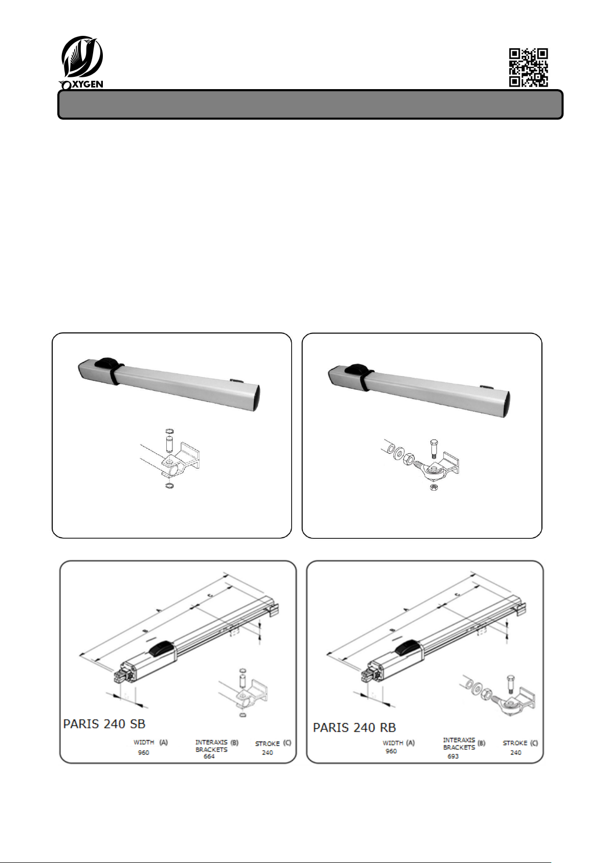
PARIS 240 SB – PARIS 240 RB
These instructions are valid for the following models:
• PARIS 240-SB R\WOL - PARIS 240-SB BA\OL – PARIS 240-SB BC\CL - PARIS 240-SB BAC\OCL
• PARIS 240-RB R\WOL - PARIS 240-RB BA\OL – PARIS 240-RB BC\CL - PARIS 240-RB BAC\OCL
The hydraulic actuators for swing gates PARIS 240-RB and PARIS 240-SB consist of an enbloc composed of
an electric pump and a hydraulic piston which transmits motion to the gate.
The models with a hydraulic block (BA - BC - BAC) do not require the installation of electro-locks, ensuring
the mechanical locking of the gate when the actuator is not in operation.
The models without hydraulic lock (R\WOL) to ensure mechanical locking of the gate require the
installation of an electric lock.
The hydraulic actuators gates PARIS 240-RB and PARIS 240-SB are designed and built to automate swing
gates; Avoid any other use.
IMAGINE
FRONT BRACKET
FRONT BRACKET
DIMESIONS
All rights reserved Pag. 3
Page 4
www.oxygenautomation.com
DATI TECNICI - DATA SHEETS - FICHES TECHNIQUES - DATOS TÉCNICOS
PARIS
PARIS
PARIS
PARIS
240- R\WOL
240- BA\OL
240- BC\CL
240-BAC\OCL
Tensione alimentazione / Power supply / Tension alimentation / Tensione de alimentación
230 Vac
230 Vac
230 Vac
230 Vac
50/60 Hz
50/60 Hz
50/60 Hz
50/60 Hz
Motore elettrico / Electric motor / Moteur electrique / Motor electrico
1400
1400
1400
1400
Corrente / Current / Courrent / Corriente
1:00 AM
1:00 AM
1:00 AM
1:00 AM
Potenza motore / Motor power / Puissance moteur / Potencia motore
250 W
250 W
250 W
250 W
Termoprotezione / Thermal protection / Protection termique / Protección térmica
120 °
120 °
120 °
120 °
Condensatore / Capacitor / Condensateur / Condensador
10 µf
10 µf
10 µf
10 µf
Forza di spinta / Thrust forcer / Force de poussé / Fuerza de empuje
550 daNm
550 daNm
550 daNm
550 daNm
Corsa stelo / Extension stem / Etendue tige / Recorrido vastago
240 mm
240 mm
240 mm
240 mm
Velocità lineare stelo / Speed linear stem / Vitesse tige linéaire / Velocidad lineal vastago
1,3 cm/sec
1,3 cm/sec
1,3 cm/sec
1,3 cm/sec
Blocco anta / Swing lock / Blocage portail / Bloqueo hoja
no
apertura / opening
chiusura /
closing
apertura-chiusura/opening-
closing
ouverture/ abertura
fermature/
cierre
ouverture-fermature/abertura-
cierre
Rallentamento corsa idraulico / Hydraulic slowdown / Rallentissement hidraulique / Parada
soave hidraulico
no
no
no
no
Portata pompa / Pump capacity / Capacité pompe / Capacidad bomba
1 l/min
1 l/min
1 l/min
1 l/min
Olio / Oil / Huile / Aceite
Total 52/AT
42
Total 52/AT 42
Total 52/AT
42
Total 52/AT 42
Temperatura di funzionamento / Operating temperature / Temperature de funtionement / Temperatura ambiente
-20° C +70°
C
-20° C +70° C
-20° C +70°
C
-20° C +70° C
Grado di protezione / Class protection / Classe de protection / Grado de protección
IP 55
IP 55
IP 55
IP 55
Peso / Weight / Poid / Peso
7 Kg
7 Kg
7 Kg
7 Kg
Dimensioni / Dimensions / Encombrement / Medidas (LxPxH)
960 x 99 x
123
960 x 99 x
123
960 x 99 x
123
960 x 99 x 123
Lunghezza anta / Leaf length / Longueur portail / Longitud de la hoja (max m.)
3
1,8
1,8
1,8
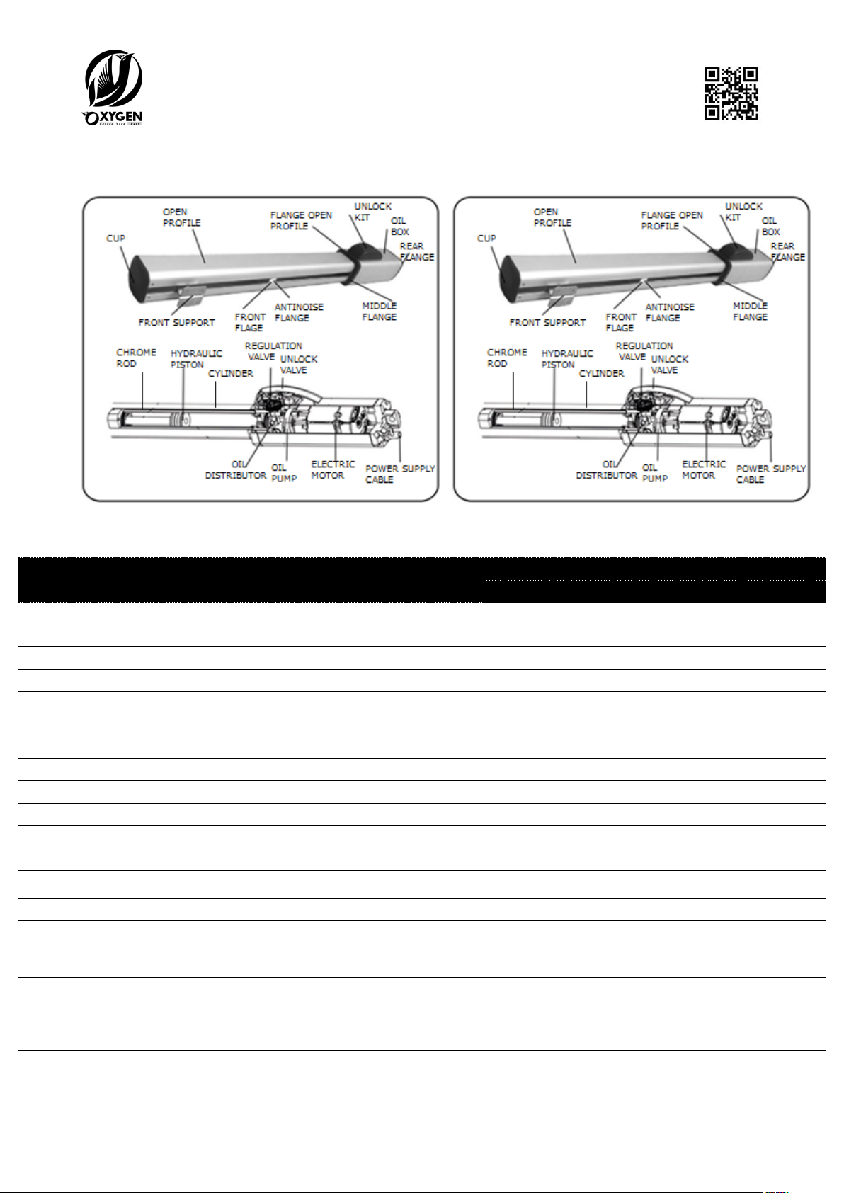
DESCRIPTION
PARIS 240 SB PARIS 240 RB
TECHNICAL DATA
All rights reserved Pag. 4
Page 5

www.oxygenautomation.com
ELECTRIC STANDAD WIRING LAYOUT
PARIS PRELIMINARY CHECKS GATE
To ensure correct operation, the gate must have the following qualifications:
- Robust and rigid structure of the doors;
- The movement of the leaves must be regular and uniform but also devoid of friction during travel;
- The hinges must be in good condition;
- Mechanical stops at the end of the race positioned.
Any metalwork operations should be carried out before the installation of the automation. The state of the
structure of the gate influences the reliability and safety of the automation.
INSTALLING PARIS 240 - FIXING PARIS 240
A) Fasten the rear attachment on the pilaster, following the indications of the table A, modify if necessary,
the length of the bracket (Fig. 1).
Compliance with the dimensions shown in the above tables ensures correct operation. In the case of iron
pillar carefully weld the rear attachment directly on the pillar.
In the case of masonry pillar opt for one of the following solutions:
1) appropriately Cashing a plate to wall and then weld the rear fitting;
2) Attach to the pillar with screws and anchors the rear mounting plate and weld on the rear
mounting plate (Fig. 2)
B) Fix the operator to the rear (fig. 2);
C) Release the hydraulic actuator PARIS 240 with release key;
D) Remove the chrome stem until total joke and bring it within approximately 5 mm (Fig. 3), and only in the
case of PARIS 240-SB installation tighten in half the front fitting (joint head) on the stem and tighten with
the supplied nut (fig. 3.1);
E) Fit the front attachment onto the rod (Fig. 4);
F) Close the gate leaf keeping the actuator perfectly horizontal and locate the front of the attack on the
wing (Fig. 5);
G) temporarily fix the front attachment on the gate using two weld points (protect the stem from any
welding slag) (fig. 6);
H) Unlock the PARIS actuator, manually check if the gate is free to open and stop the mechanical stops to
end preinstalled race; Furthermore, check the movement of the gate is regular and without friction;
I) momentarily disconnect the actuator and weld the front attachment on permanently (fig. 7)
L) Place the cover on the actuator rod PARIS (fig. 7);
M) Re-lock the PARIS actuator and make the electrical connections with the electronic equipment,
according to the instructions in the manual.
All rights reserved Pag. 5
Page 6

www.oxygenautomation.com
FIXING REAR SUPPORT
PARIS 240 RB – PARIS 240 SB
Fig.1
Fig.2 fig. 2.1
In the case that the size of the pillar or the position of the Hinge (D share) does not allow to contain the
A in desidered measure, you must make a niche on pillar (Fig. 2.1).
Dimension A must always be greater than the proportion E.
TABLE REAR SUPPORT FIXING
(*) Rod effective stroke (**) maximum quota
c = The stroke of the rod is less than the maximum stroke in order to prevent the piston arrives internally in
abutment in the opening and closing phases
All rights reserved Pag. 6
Page 7

www.oxygenautomation.com
FIXING FRONT SUPPORT PARIS 240MM SB
All rights reserved Pag. 7
Page 8

www.oxygenautomation.com
FIXING FRONT SUPPORT PARIS 240MM RB
PARIS 240 RB PARIS 240 SB FIXING ROD COVER
All rights reserved Pag. 8
Page 9

www.oxygenautomation.com
PARIS 240 SB – PARIS 240 RB
CONTROL SYSTEM ANTI CRUSHING
- FINAL OPERATIONS - AUTOMATED TEST
ANTI-CRUSHING SYSTEM ADJUSTMENT (Figure 8)
The hydraulic actuator BATHY is equipped with an
anti-crushing security that limits the actuator
force the same, in the presence of an obstacle
during the movement of the gate. The force is
adjusted as follows:
- Slide the cap to unlock and lift it;
- Lift the base of the release group;
- The regulating valves: valve "A" to adjust the
opening force, the valve "B" to adjust the closing
force and valve "C" to unlock completely.
By turning the valves clockwise increases the
torque, while counter-clockwise to decrease the
torque.
The adjustment of the torque, in the states of the
European Union, is subject to the standards EN
12445 and EN
12453. In the other states is subject to local
regulations.
FIG.8
FINAL OPERATIONS
On completing the adjustment operations of the
anti-crushing system, proceed as follows:
Fig. 9
Vent Screw
- Reseal the release unit device;
- Remove the vent screw (Fig. 9).
AUTOMATED TEST
After installation, proceed with care to the
functional test automation and of all accessories
connected with particular attention to the safety
devices.
Deliver to the owner of the "User's Guide" and
explain correct operation and use of the
automated system, and indicate the potentially
dangerous areas thereunder
OPERATION MANUAL RESET
OPERATION MANUAL
In case you need to manually operate the gate to
the absence of electrical power cut or failure, you
must use the release device as follows:
- Open the cover cap release and insert the key
provided;
- Turn the key counter-clockwise to unlock;
- Manually perform the maneuver of opening or
closing of the door of the gate.
RECOVERY AUTOMATED SYSTEM
Before proceeding to the restoration of the
automated system, following manual release, it is
advisable to switch off the system power supply,
in order to prevent an involuntary pulse from
activating the automation.
The restore operation must be carried out as
follows:
- Turn the release key clockwise until it stops;
- Close the cover cap of the release system;
- Replace the electric power system;
- Start the automation.
MAINTENANCE AND REPAIR
MAINTENANCE
It is recommended the functional verification
every six months, particularly the efficiency of the
safety and release devices, including verification
of the actuator thrust force; it is also good to
check the degree of the gate hinges.also check
the oil level in the tank.
All rights reserved Pag. 9
Page 10

www.oxygenautomation.com
Gate does not move
- Mains power supply control
- Ensure that the operator is not unlocked
- Check valves to force adjustment
- Check oil level in the tank
- Check efficiency starting capacitor
- Check function electronic control unit
Gate moves slowly
- Control adjustment anti-crushing system
Gate moves in jerks
- Verify the removal of the oil vent screw
- Eliminate any possible air inside the piston,
performing complete cycles of opening and closing of
the gate
Oil from the vent screw (leackage)
- It is normally a minimum initial oil leackage, if leackage
is continuing, verify that the actuator is in the horizontal
position. If not, contact an authorized service center.
Leaf stop in slowing phase
- Control adjustment anti-crushing system
Gate no constant running speed
- Check the angle of opening odds
In case of oil topping you must absolutely use oil Total 52-AT42
Periodically check the correct adjustment anti-crushing safety (force control valves) and the efficiency of
the release system.
REPAIR
Any Automatic System repairs must be performed by qualified staff, possibly authorized Oxygen
Automation.
Use original spare parts provided by Oxygen Automation.
TROUBLESHOOTING
All rights reserved Pag. 10
Page 11

www.oxygenautomation.com
END USER INSTRUCTION MANUAL
HYDRAULIC ACTUATORS FOR SWING GATE PARIS 240 RB AND PARIS 240 SB
Read the instructions carefully before using the product and store them for future use
GENERAL SAFETY
The hydraulic operator PARIS, when properly installed and used, guarantees a high degree of safety.
Some simple rules on behavior can prevent accidental trouble:
- Do not pass through the leaves while they are moving. Before passing through the leaves, wait for the
complete opening.
- Do not stand between the leaves.
- Do not stop and do not allow children, persons or things to stand there, especially while it is operating.
- Keep out of the reach of children, remote controls or any other pulse to prevent the automated system
from being activated involuntarily.
- Do not allow children to play with the automation.
- Do not impede the movement of the leaves.
- Prevent any branches or shrubs from interfering with leaf movement.
- Maintain efficient and easy to see light signaling systems.
- Not groped to manually activate the leaves if you have released them.
- In case of a malfunction, release the leaves to allow access and wait for the technical intervention of
qualified personnel.
- Once you have set the manual mode, before restoring normal operation, disconnect the power supply.
- Do not modify the components of the automation system.
- Do not attempt to repair or intervene directly and contact only qualified personnel.
- At least once every six months the automated system, safety devices and the earth connection checked by
qualified personnel.
OPERATION MANUAL
If you need to operate the gate manually because of a power failure or malfunction you need to
temporarily open the release unit.
- Open the protective cap and insert the supplied key
-Rotate The key counter-clockwise to unlock. -Rotate The key clockwise to lock.
Make the maneuver of opening or closing of the leaf.
N.B .: in NOBLOCK (WOL) models need to manually release the electric lock.
Restore the normal operation must be done, after disarming power, turning clockwise the release key until
it stops. Close the protective cap of the release unit.
DESCRIPTION
These instructions are valid for the following models: PARIS 240-SB R\WOL – PARIS 240-SB BA\OL - PARIS
240-SB BC\CL - PARIS 240-SB BAC\OCL - PARIS 240-SB R\WOL PARIS 240-SBBA\OL -PARIS 240-SB BC\CL –
PARIS 240-SB BAC\OCL.
PARIS 240 actuators for swing gates are hydraulic units comprising an electric pump and a hydraulic piston
which transmits motion to the leaf.
All rights reserved Pag. 11
Page 12

www.oxygenautomation.com
Models with a hydraulic locking do not need to install the electric lock, ensuring the mechanically locked
when the motor is not running.
Others without hydraulic block (WOL) models require one or more electric locks to ensure mechanical
locking.
Operators are controlled by an electronic control unit, housed in an enclosure which assures adequate
protection against atmospheric agents.
The leaves are normally in the closed position. When the electronic control unit receives an opening
command via the radio control or any other pulse generator, it activates the hydraulic appliance which
rotates the leaves until they reach the opening position allowing access.
If you have set the automatic operation, the doors close automatically after the selected pause time.
If semiautomatic operation has been set, it must send a second pulse to close the gate again. A stop pulse
(if supplied) always stops movement. For details on the behavior in different function logics, consult the
installation technician.
Automated systems include safety devices (photocells) which prevent the leaves from moving when there
is an obstacle in the area they protect.
PARIS 240 actuator comes standard with a hydraulic anti-crushing safety device that limits the torque
transmitted to the leaves.
Light indicates the current leaf movement.
www.oxygenautomation.com
CONFORMITY DECLARATION FOR MACHINERY
(DIRECTIVE 98/37 CEE)
Manufactured under CE regulation and directive in ITALY and Distributed in EUROPEAN
UNION and OVERSEAS by OXYGEN AUTOMATION Srl, via Marzabotto, 40133
Bologna ITALIA
Declares: That hydraulic operators for swings gates mod. PARIS 240 RB and PARIS 240 SB
• are designed to be incorporated into machinery or to be assembled with other machinery to
constitute machinery under the Directive 98/37 CEE and subsequent amendments;
• meet the essential safety requirements of the following Directives CEE:
73/23 CEE and subsequent amendment 93/68/CEE
89/336 CEE and subsequent amendment 92/31 CEE and 93/68 CEE.
Declares: It is not allowed to put in service the machinery up to that the car in which it will be
incorporated or which will become component has been identified and has been declared the
conformity under the conditions of the Directive 98/37/CEE and subsequent amendment.
The Legal Representative
All rights reserved Pag. 12
 Loading...