

Page 1
NOTE:
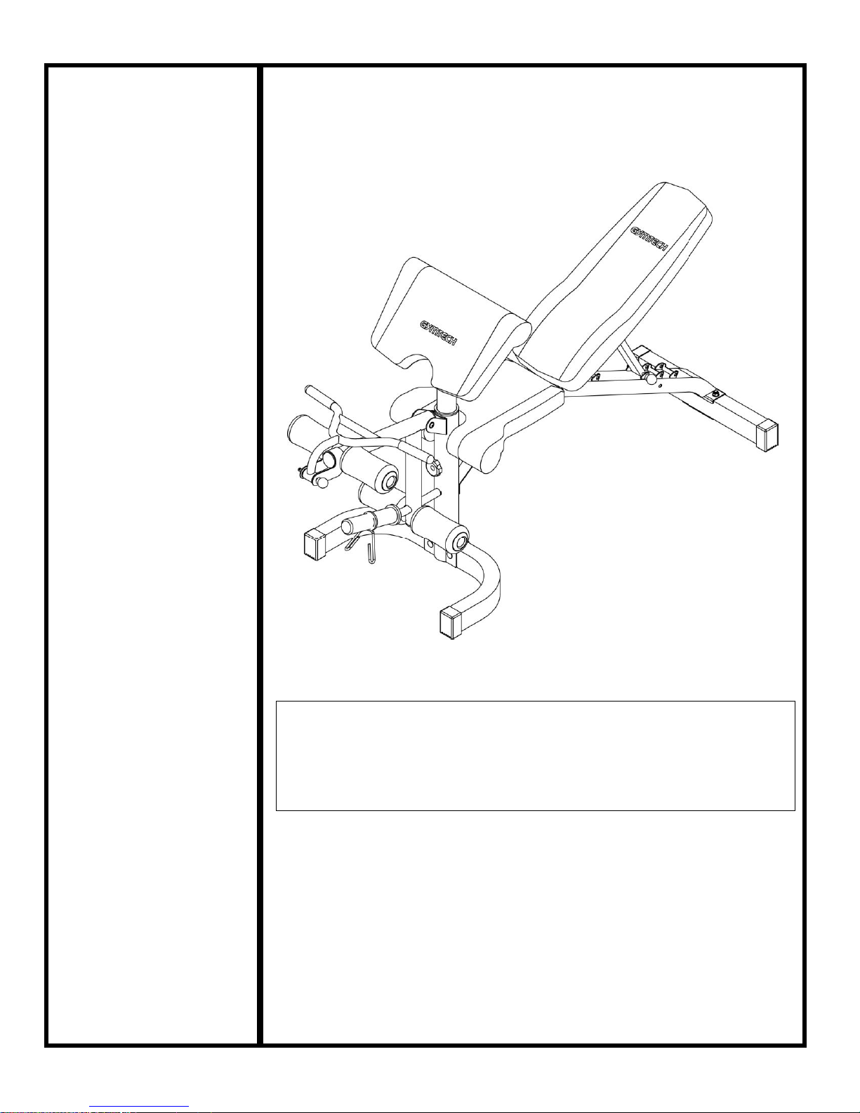
Please read all instructions
carefully before using this
product
Table of Contents
Safety Notice
Hardware Identifier
Assembly Instruction
Parts List
Warranty
Ordering Parts
Model
50951
Retain This
Manual for
Reference
02-07-2014
OWNER'S
MANUAL
FORT SMITH
Please contact HUNTER LEISURE AUSTRALIA Should any
questions arise at 1800-632-792
Spare Part Service: If you require Spare Part service, please do
not return the Power Bench to the store. Contact Hunter Leisure
Australia on 1800-632-792.
http://winner-oxygen.ru
http://winner-oxygen.ru
Page 2
ASSEMBLY INSTRUCTION
DIAGRAM 1
http://winner-oxygen.ru
http://winner-oxygen.ru
Tools Required Assembling the Machine: Two Adjustable Wrenches and Allen
Wrenches
NOTE: It is strongly recommended two or more people assembling this machine to
avoid possible injury. Do not tighten all the bolts and nuts until getting instruction.
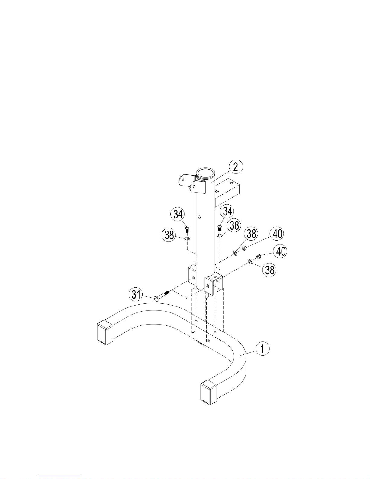
STEP 1 (See Diagram 1)
A Attach the upright beam (#2) to the front stabilizer (#1), and secure them horizontally
with two M10×70mm Carriage bolts (#31), two Ø 10mm washers (#38), two aircraft
nuts (#40).And then secure them vertically with two M10×20mm Allen bolt (#34), two Ø
10mm Washers (#38).
STEP 2 (See Diagram 2)
A Attach the one end of the seat pad support frame (#3) to the rear stabilizer (#4).
5
Page 3
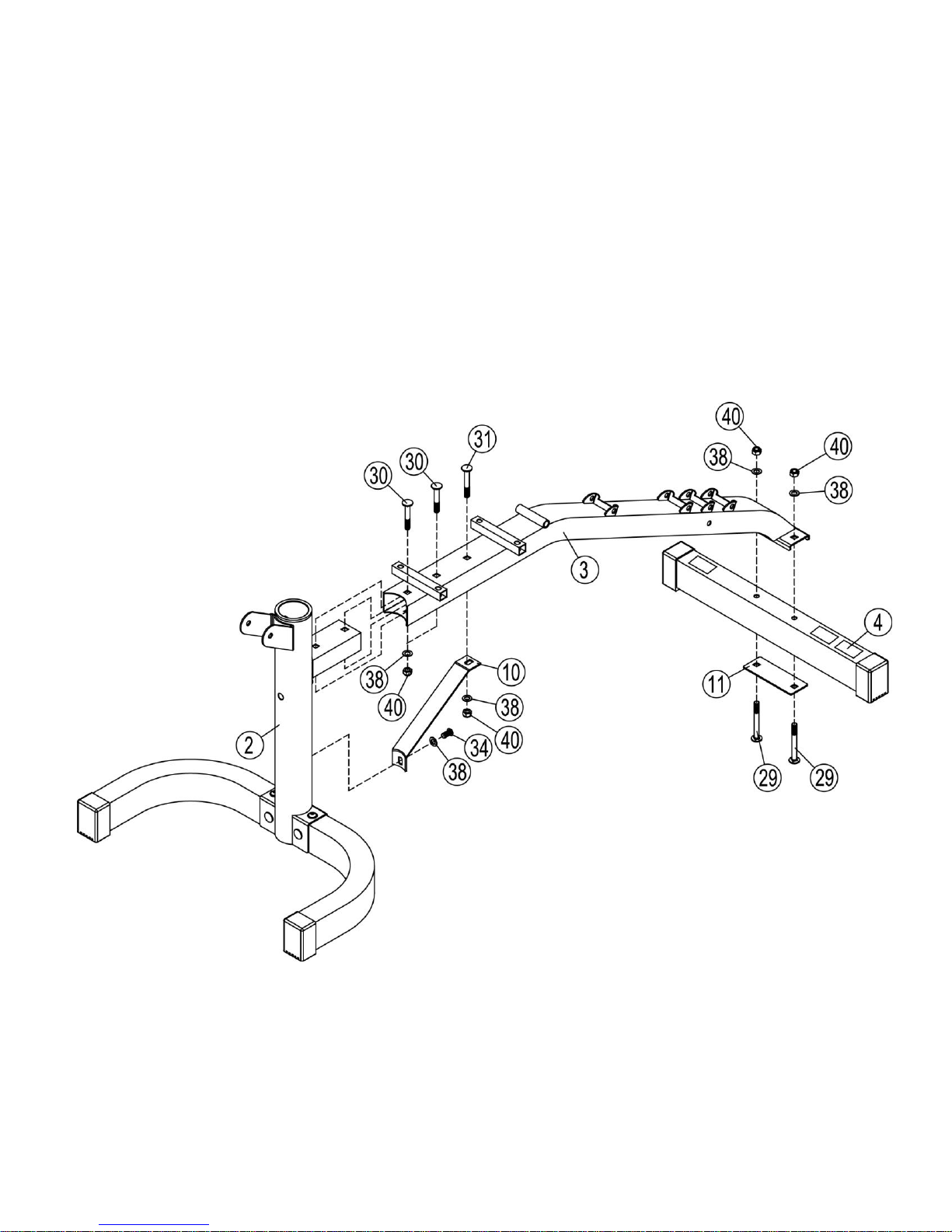
Secure them with two M10×90mm carriage bolts (#29), one flat connection (#11), two
DIAGRAM 2
http://winner-oxygen.ru
http://winner-oxygen.ru
Ø10mm Washers (#38), two M10 aircraft nut (#40) .DO NOT tighten the bolts yet.
B Attach another end of the Seat pad Support frame (#3) to the upright beam (#2) and
secure them with two M10×63mm Carriage Bolt (#30), two Ø10mm washers (#38), two
M10 aircraft nuts (#40).
C. Attach one end of the bracket (#10) to the upright beam (#2), and secure them with one Ø
10mm Washer (#38), one M10×20mm Allen bolt (#34). Attach the other end of the bracket to
the seat pad support frame (#3), secure them with One M10×70mm carriage bolt (#31), Ø
10mm washer (#38), One M10 aircraft nut (#40).
6
Page 4
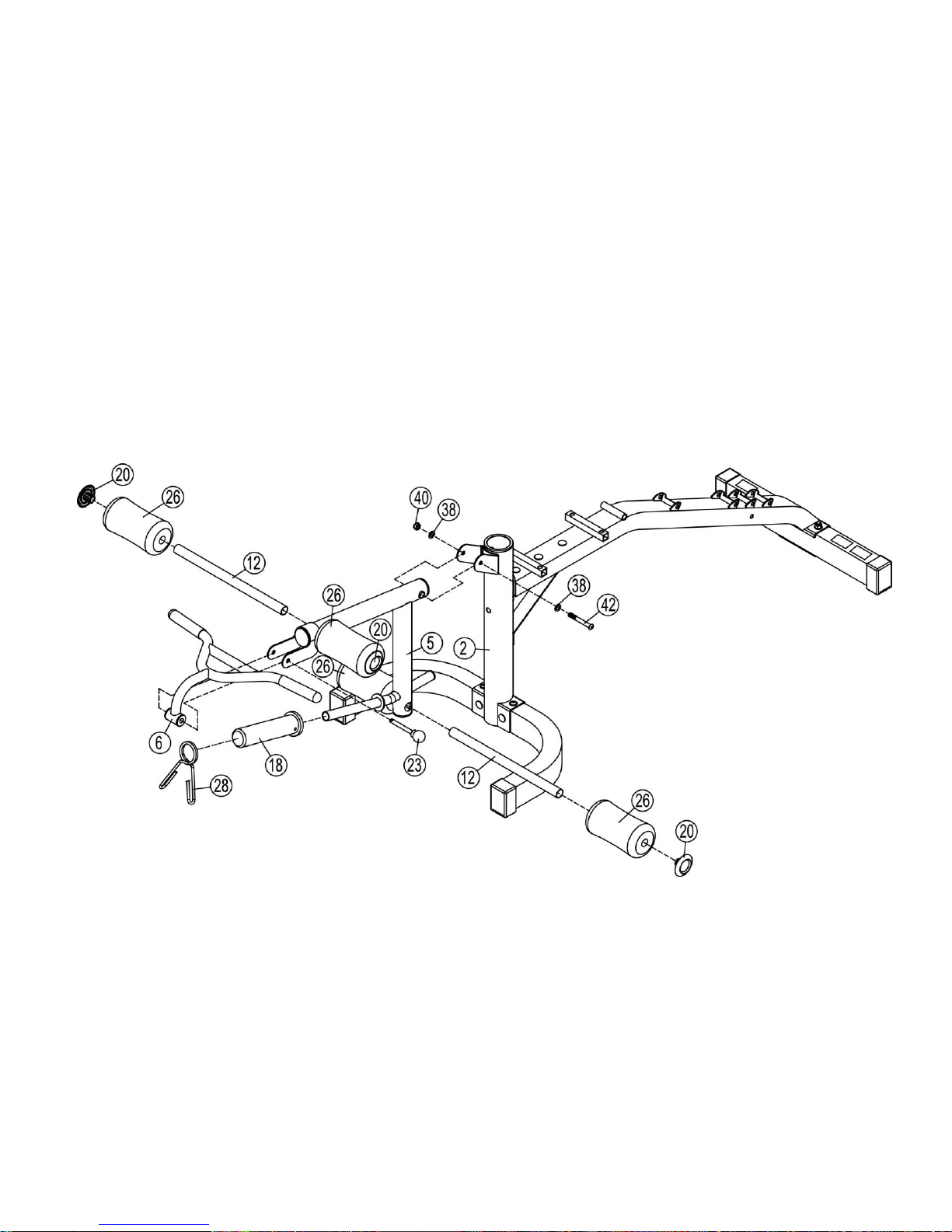
STEP 3 (See Diagram 3)
http://winner-oxygen.ru
http://winner-oxygen.ru
A Attach the leg developer (#5) to the upright beam (#2). Secure them with one M10×
80mm allen bolt (#42), two Ø10mm washers (#38), one M10 Aircraft nut (#40).
B Insert two foam roll tubes (#12) halfway through the holes on the leg developer. Push
four foam rolls (#26) onto the tubes from both sides and push the four Ø25×1.3mm
end cap (#20) to the foam roll.
C Place a sleeve (#18) and a spring clip (#28) onto the weight post on the leg developer.
Attach the handle to the leg developer (#5), and secure them with Ø10×100 pin(#23).
DIAGRAM 3
STEP 4 (See Diagram 4)
A Attach the backrest support (#8) onto the seat pad support frame (#3), align the holes
7
Page 5
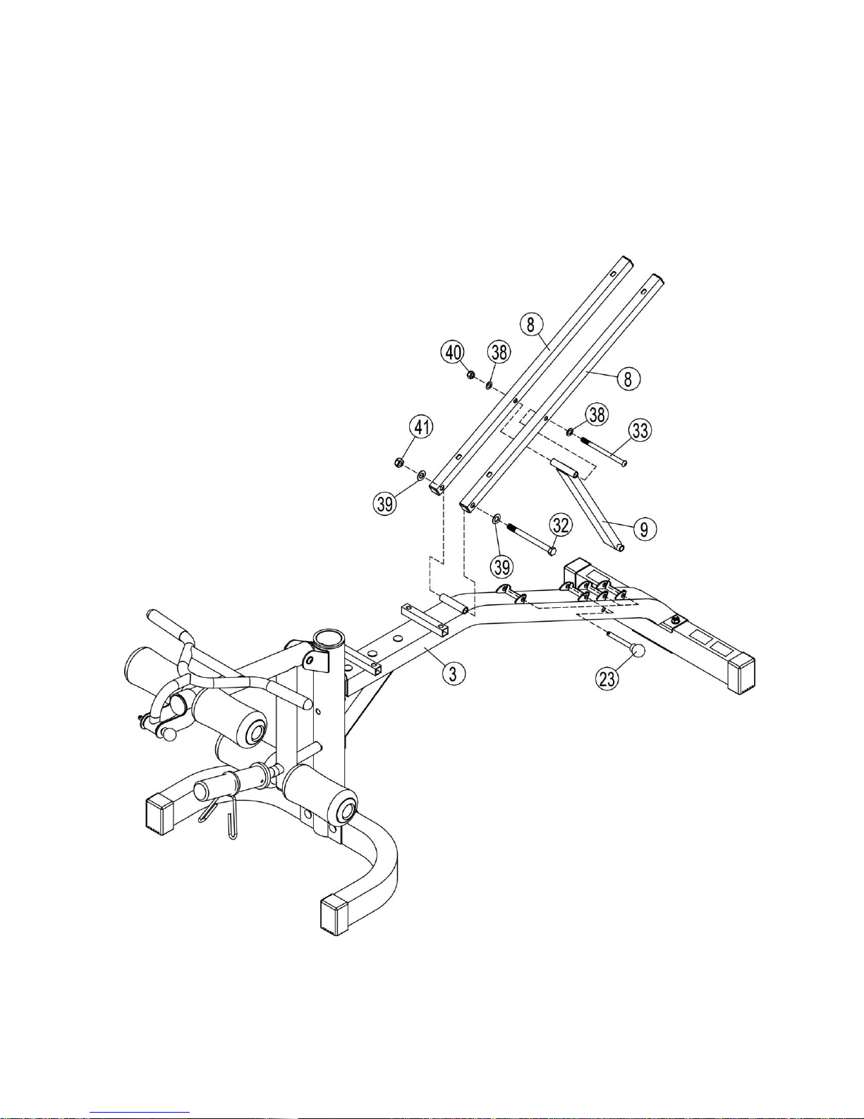
and secure them with one M12×145mm allen bolt (#32) and two Ø12mm washer
http://winner-oxygen.ru
http://winner-oxygen.ru
(#39), one M12 Aircraft nut (#41).
B Attach the backrest incline pad support (#9) to the backrest support (#8), and secure
them with one M10×145mm Allen Bolt (#33), two Ø10mm washers (#38), one M10
aircraft nut (#40).
DIAGRAM 4
8
Page 6

STEP 5 (See Diagram 5)
http://winner-oxygen.ru
http://winner-oxygen.ru
A Attach the seat pad (#14) onto the seat pad support frame (#3), align the holes secure them
with four M10×40mm allen bolts (#35) and four ø8mm washers (#37).
B Attach the backrest pad (#13) to the backrest pad supports (#8), align the holes and
secure them with four M10×40mm allen bolts (#35) and four Ø8mm washers (#37).
DIAGRAM 5
9
Page 7

STEP 6 (See Diagram 6)
http://winner-oxygen.ru
http://winner-oxygen.ru
A Insert the arm curl pad support (#7) to the hole of upright beam (#2), and secure them
with M10×90mm Lock pin (#17) to adjust different height.
B Attach the arm curl pad (#15) to the arm curl pad support (#7), and secure them with two
Ø8mm washers (#37), two M8×16mm allen bolts (#36).
C Tighten all the bolts and nuts when finishing assembling.
DIAGRAM 6
Exploded Diagram
10
Page 8

PARTS LIST
Key
No.
Description
QTY
Key
No.
Description
QTY
http://winner-oxygen.ru
http://winner-oxygen.ru
11
Page 9

1
Front stabilizer
1
27
Ø18×Ø10×12 bushing
2
2
Upright beam
1
28
Ø49 spring clip
1 3 Seat pad support frame
1
29
M10×90mm Carriage bolt
2
4
Rear stabilizer
1
30
M10×63mm Carriage bolt
2 5 Leg developer
1
31
M10×70mm Carriage bolt
3
6
Handle
1
32
M12×145mm Hex bolt
1 7 Arm curl pad support
1
33
M10×145mm Allen bolt
1
8
Backrest pad support
2
34
M10×20mm Allen bolt
3 9 Backrest pad incline support
1
35
M8×40 mm Allen bolt
8
10
Bracket
1
36
M8×16mm Allen bolt
2
11
Flat connection
1
37
Ø8 washer
10
12
Foam roll tube
2
38
Ø10 washer
14
13
Bracket pad
1
39
Ø12 washer
2
14
Seat Pad
1
40
M10 mm Aircraft nut
9
15
Arm curl Pad
1
41
M12 mm Aircraft nut
1
16
Ø25×2 end cap
1
42
M10×80 mm Allen bolt
1
17
M10×90 lock pin
2
43
Ø50×1.5End cap
3
18
Ø50×Ø26.5×200 mm sleeve
1 4# Allen Wrench
1
19
End cap
4 5# Allen Wrench
1
20
Ø25×1.3mm end cap
4 6# Allen Wrench
1
21
□25×2 End cap
4
22
Ø76×60 Sleeve
1 23
Ø10×100 Pin
1
24
Ø32 bushing
2 25
Ø25×130 grip
2
26
Ø22×Ø100×180 foam roll
4
http://winner-oxygen.ru
http://winner-oxygen.ru
12
Page 10

3 ASSEMBLY INSTRUCTION
DIAGRAM 1
http://winner-oxygen.ru
http://winner-oxygen.ru
Tools Required Assembling the Machine: Two Adjustable Wrenches and Allen
Wrenches
NOTE: It is strongly recommended two or more people assembling this machine to
avoid possible injury.Do not tighten all the bolts and nuts until getting instruction.
STEP 1 (See Diagram 1)
A. Attach the right upright beam (#2) to the right stabilizer (#1), and secure them with one
flat connection (#9), two M10×90mm carriage bolt (#18), two Ø10 washer (#23), two M10
aircraft nut (#21). And then secure them horizontally with two M10×70mm carriage bolt
(#19), two Ø10 washer (#23), M10 two aircraft nut (#21) again.
B. Attach the curved end of the triangle support (#4) to the right upright beam (#2), and
secure them with curved bracket (#10), two M10×95mm carriage bolt (#17), two Ø10
washer (#23), two M10 aircraft nut (#21). Attach the other end of the triangle support (#4)
to the right stabilizer (#1). Then secure them with one flat connection (#9), two M10×
90mm carriage bolt (#18), two Ø10 washer (#23), two M10 aircraft nut (#21).
STEP 2 (See Diagram 2)
4
Page 11

A. Repeat the same method of diagram 1 to install the left stabilizer (#1), left upright beam
DIAGRAM 2
http://winner-oxygen.ru
http://winner-oxygen.ru
(#2), and triangle support (#3).
5
Page 12

STEP 3 (See Diagram 3)
http://winner-oxygen.ru
http://winner-oxygen.ru
A. Attach the cross beam (#5) to the left triangle support (#4). Secure them with two M10×
60mm carriage bolt (#20), one flat connection (#9), two Ø10 washers (#23), two M10
aircraft nut (#21).
B. Repeat the same method to attach the end of the cross beam (#5) to the right support and
install them.
DIAGRAM 3
STEP 4 (See Diagram 4)
6
Page 13

A. Attach the weight poster (#6) to the left triangle support (#3), align the hole, secure them
http://winner-oxygen.ru
http://winner-oxygen.ru
with one M10×25mm Allen bolt (#22) and one Ø10mm washer (#23). Place the sleeve
(#13) and spring clip (#16) onto the weight poster (#6).
B. Repeat the same method to install the other.
DIAGRAM 4
7
Page 14

STEP 5 (See Diagram 5)
http://winner-oxygen.ru
http://winner-oxygen.ru
A. Attach the two short crunch (#8) to the hole of the upright beam (#2).
B. Attach the two long crunch (#7) to the hole of the upright beam (#2).
Make sure place the bulge of the crunch into the holes entirely when exercising .
Tighten all the bolts and nuts when finishing assembling
DIAGRAM 5
Exploded Diagram
8
Page 15

http://winner-oxygen.ru
http://winner-oxygen.ru
9
Page 16

PARTS LIST
Key
No.
Description
QTY
Key
No.
Description
QTY
1
Stabilizer
2
22
M10×25mm Allen Bolt
2 2 Right /left Upright beam
2
23
Ø10 Washer
22
3
Left support
1 4#Allen wrench
1 4 Right support
1 6#Allen wrench
1
5
Cross beam
1 6
Weight poster
2
7
Long crunch
2
8
Short crunch
2
9
Flat connection
6 10
Curved bracket
2
11
Ø76×1.5 End cap
2 12
Ø25×2.0 End Cap
4
13
Ø50×Ø26.5×200 sleeve
2 14
□50×70 End cap
1
15
Ø25×2.0 End cap
2 16
Ø49 Spring clip
2
17
M10×95mm Carriage Bolt
4 18
M10×90mm Carriage Bolt
8
19
M10×70mm Carriage Bolt
4 20
M10×60mm Carriage Bolt
4
21
M10 Aircraft Nut
20
http://winner-oxygen.ru
http://winner-oxygen.ru
 Loading...