

Page 1
PLA200
PowerLine Communication
May 10, 2004
PLA200 Powerline adapters plug into an electrical
outlet to convert the power system into a LAN or
WAN network.
The PLA200 adaptor creates a smart access
point providing Ethernet access at speeds of up
to 14 Mbps with an automatic repeater function,
and offers advanced administration features and
greater security.
PLRP Automatic Repeater Mode
(PowerLine Routing Protocol)
Oxance has developed a powerful routing algorithm
specically for powerline communications, which
enables the PLA200 to act in automatic repeater
mode in transmit and/or receive, guaranteeing
optimal bandwidth and increasing the coverage
of your powerline network.
Advanced Administrative Functions
Managing your powerline network is easy with
the PLA200, which includes an HTTP server,
making the conguration interface compatible
with all operating systems.
An SNMP V1, V2c and V3 agent with trap control
ensures compatibility with other network
administrators.
A Syslog daemon logs system events. An integrated
network performance utility displays the powerline
network performance in real time.
Upgradable rmware in the PLA200 can be
updated via the network.
Enhanced Security Level
MAC address ltering means you can eliminate
the Network Neighbourhood on Windows PCs,
enable or disable PLA200 use or conguration,
control network access, and control the bandwidth
allocated to users.
The AES 128 bit encryption protocol guarantees
the integrity and security of data transmissions.
Optionally, it may be used with the DES 56 bit
security protocol included in the HomePlugTM
1.0.1 protocol.
The PLA200 offers two-layer data security without
sacricing performance.
For optimal use of your PLC modules, we recommend
that you read this manual carefully.
For more information on our products, please
visit our website : www.oxance.com
Page 2

CONTENTS 2
Contents
1 Safety Instructions 4
2 The Powerline Communication Network 5
3 The Most Common Architectures 6
3.1 Your business network via electrical outlets. . . . . . . . . . . . . . . . . . . 6
3.2 Schools, government office, museums, hotels . . . . . . . . . . . . . . . . . 7
3.3 Industries, services, stores . . . . . . . . . . . . . . . . . . . . . . . . . . . . 8
4 The Advanced Features of the PLA200 9
4.1 Dynamic Routing (selecting the best route) . . . . . . . . . . . . . . . . . . 9
4.2 Automatic Repeater (improving distances) . . . . . . . . . . . . . . . . . . . 10
4.3 MAC Address Filtering . . . . . . . . . . . . . . . . . . . . . . . . . . . . . . 10
4.4 Managing Bandwidth . . . . . . . . . . . . . . . . . . . . . . . . . . . . . . . 11
4.5 Communications Counter (kbytes) . . . . . . . . . . . . . . . . . . . . . . . 11
4.6 Complete infor mation about the status of the powerline network (best
routes, noise, network quality) . . . . . . . . . . . . . . . . . . . . . . . . . . 11
4.7 DES 56 bit and AES 128 bit Security Protocols . . . . . . . . . . . . . . . . 11
4.8 Configuration by HTTP Server . . . . . . . . . . . . . . . . . . . . . . . . . . 12
4.9 SNMP V1, V2, and V3 Agent with Trap Control . . . . . . . . . . . . . . . . 12
4.10Locating a Remote PLA200 . . . . . . . . . . . . . . . . . . . . . . . . . . . . 12
5 Product Presentation 13
5.1 Package Contents . . . . . . . . . . . . . . . . . . . . . . . . . . . . . . . . . 13
5.2 Required Configuration . . . . . . . . . . . . . . . . . . . . . . . . . . . . . . 13
5.3 Description of the Device . . . . . . . . . . . . . . . . . . . . . . . . . . . . . 14
5.3.1 Lights . . . . . . . . . . . . . . . . . . . . . . . . . . . . . . . . . . . . 14
5.4 Features and Recommendations . . . . . . . . . . . . . . . . . . . . . . . . . 15
6 Installing the PLA200 16
7 Configuring the IP address 17
7.1 New Network or Existing Network . . . . . . . . . . . . . . . . . . . . . . . . 17
7.2 Example of IP address assignment (auto_ip mode) . . . . . . . . . . . . . . 18
8 Graphic Configuration 19
8.1 Home Page . . . . . . . . . . . . . . . . . . . . . . . . . . . . . . . . . . . . . 19
8.2 Global Network . . . . . . . . . . . . . . . . . . . . . . . . . . . . . . . . . . . 22
8.2.1 Global Network - Products List . . . . . . . . . . . . . . . . . . . . . . 22
8.2.2 Global Network - Quality . . . . . . . . . . . . . . . . . . . . . . . . . 24
8.2.3 Global Network - Setup . . . . . . . . . . . . . . . . . . . . . . . . . . 27
8.2.4 Global Network - Security . . . . . . . . . . . . . . . . . . . . . . . . . 31
8.2.5 Global Network - Test . . . . . . . . . . . . . . . . . . . . . . . . . . . 38
8.2.6 Global Network - Monitoring . . . . . . . . . . . . . . . . . . . . . . . 39
Page 3

CONTENTS 3
8.2.7 Global Network - Save Config . . . . . . . . . . . . . . . . . . . . . . . 40
8.3 PLA Selection . . . . . . . . . . . . . . . . . . . . . . . . . . . . . . . . . . . . 41
8.3.1 PLA Selection - Setup . . . . . . . . . . . . . . . . . . . . . . . . . . . 42
8.3.2 PLA Selection - System Log . . . . . . . . . . . . . . . . . . . . . . . . 46
8.3.3 PLA Selection - Route . . . . . . . . . . . . . . . . . . . . . . . . . . . 48
8.3.4 PLA Selection - LAN/PLA . . . . . . . . . . . . . . . . . . . . . . . . . 49
8.3.5 PLA Selection - Save Config . . . . . . . . . . . . . . . . . . . . . . . . 50
9 PLA 220 (Bridge) 51
9.1 PLA200 Compatibility with HomePlug 1.0.1 devices . . . . . . . . . . . . . 52
9.2 Segment a Powerline Network . . . . . . . . . . . . . . . . . . . . . . . . . . 55
9.3 Examples of how PLA bridges are used . . . . . . . . . . . . . . . . . . . . . 58
9.3.1 A Powerline Network with 15 PLA200s and 15 PL100s . . . . . . . . 58
9.3.2 A Powerline Network composed of 21 PLA200s . . . . . . . . . . . . 59
9.3.3 A Powerline Network composed of 75 PL100s . . . . . . . . . . . . . 60
9.3.4 A Powerline Network composed of 75 PLA200s . . . . . . . . . . . . 61
9.3.5 A Powerline Network composed of 21 PLA200s and 30 PL100s . . . 62
10 Specifications 63
11 Troubleshooting 64
12 Mounting Kit 65
13 Data Sheets 66
13.1How do I find the MAC address of a network device? . . . . . . . . . . . . 66
13.2Updating the PLA2xxs . . . . . . . . . . . . . . . . . . . . . . . . . . . . . . . 68
13.3Setup and optimize a PLC network with a PocketPC . . . . . . . . . . . . . 72
14 Glossaire 78
15 Note 80
Page 4

1 SAFETY INSTRUCTIONS 4
1 Safety Instructions
This device is intended for use in alternating current (AC) electrical systems.
Please take the following precautions :
Read and follow all of the safety instructions and warnings appearing on the device and in this manual.
Your electrical system must be equipped with a circuit breaker to prevent short circuits.
Make sure that your electrical outlets are equipped with fuse or circuit-breaker protection with a maximum
current of 16 Amps.
Slots and openings on the case are provided for ventilation.
To ensure reliable operation of the device and to protect it from overheating, never block or cover the slots or
openings.
Power supply cords should be routed so that they are not likely to be stepped on or pinched by items placed
on or against them.
It should not be installed in a location exposed to direct sunlight or heat sources.
Never use liquid or aerosol cleaners.
If necessary, unplug the device and clean it with a damp cloth.
Never use this device near a source of water, for example, a bathtub, sink, washing machine, a damp cellar
or near a swimming pool.
The device should be operated only from the type of power source indicated on the device’s electrical ratings
label.
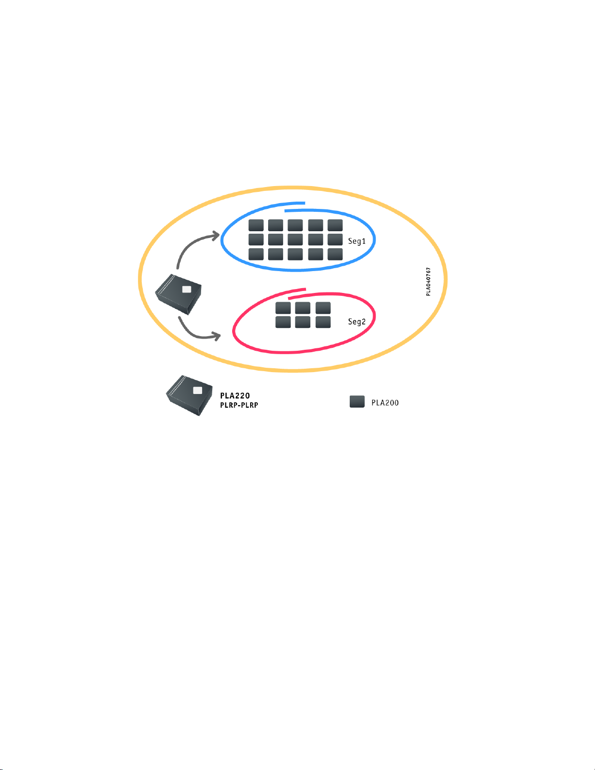
Do not overload wall outlets and extension cords as this can result in a risk of fire or electrical shock.
Do not attempt to service this device yourself.
Opening or removing covers may expose you to dangerous voltage or other hazards, and cancels the
warranty.
None of the internal parts can be replaced except by qualified service personnel, so you should not open the
device.
If your device needs servicing, contact an authorised service provider.
Unplug the unit from the wall outlet and have it repaired by qualified service personnel under the following
conditions :
If the power-supply cord or plug is damaged.
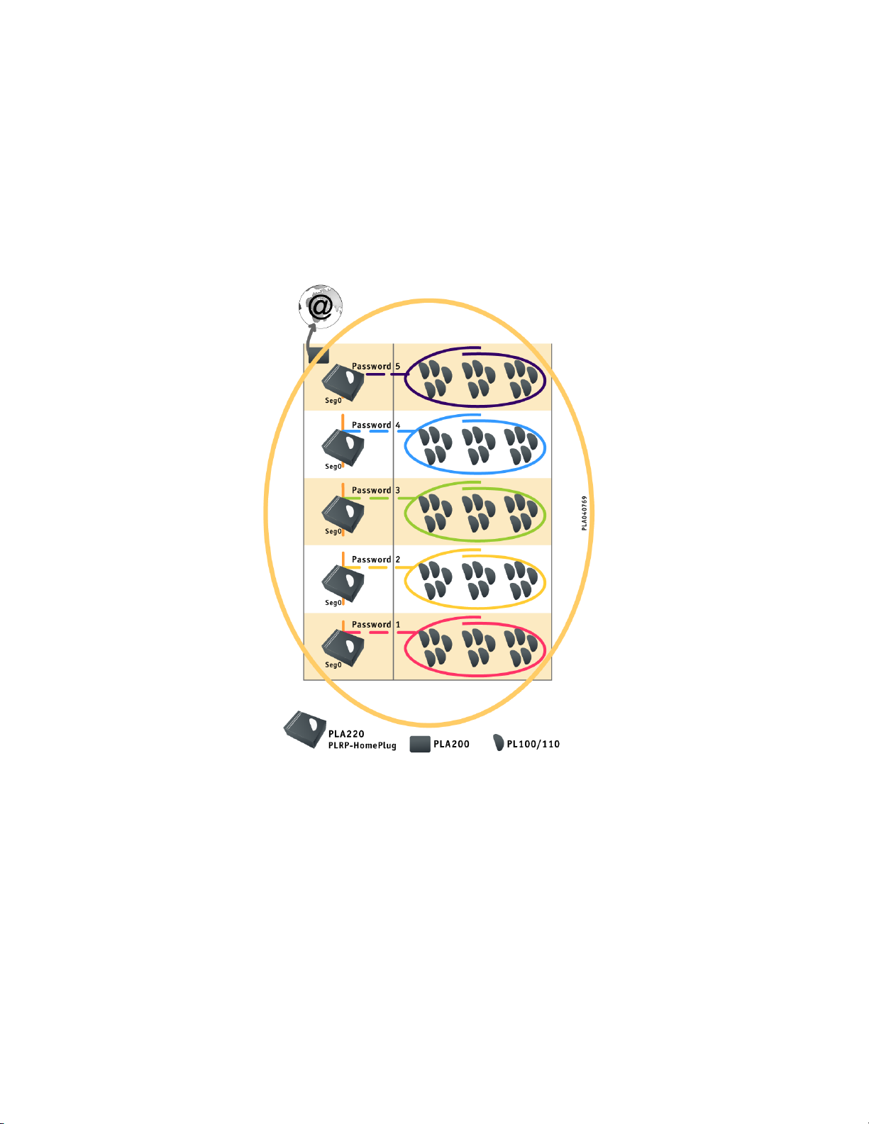
If liquid has been spilled into or onto the device.
If the device has been exposed to rain or water.
If the device does not operate normally.
If the device has been dropped or damaged in any way.
If the device exhibits a distinct change in performance.
Page 5

2 THE POWERLINE COMMUNICATION NETWORK 5
2 The Powerline Communication Network
Powerline Communications (PLC) technology uses the existing power system to communicate
without the need for additional or specific wiring. PLCnetTMdevices use the existing electrical
wiring to transport information. The technology consists of overlaying a higher frequency (4.3
to 20.9 Mhz bandwidth), low-power signal on top of the 50 Hz signal. This signal travels over
the electrical wires and is then received and decoded by all the PLCnetTMdevices on the power
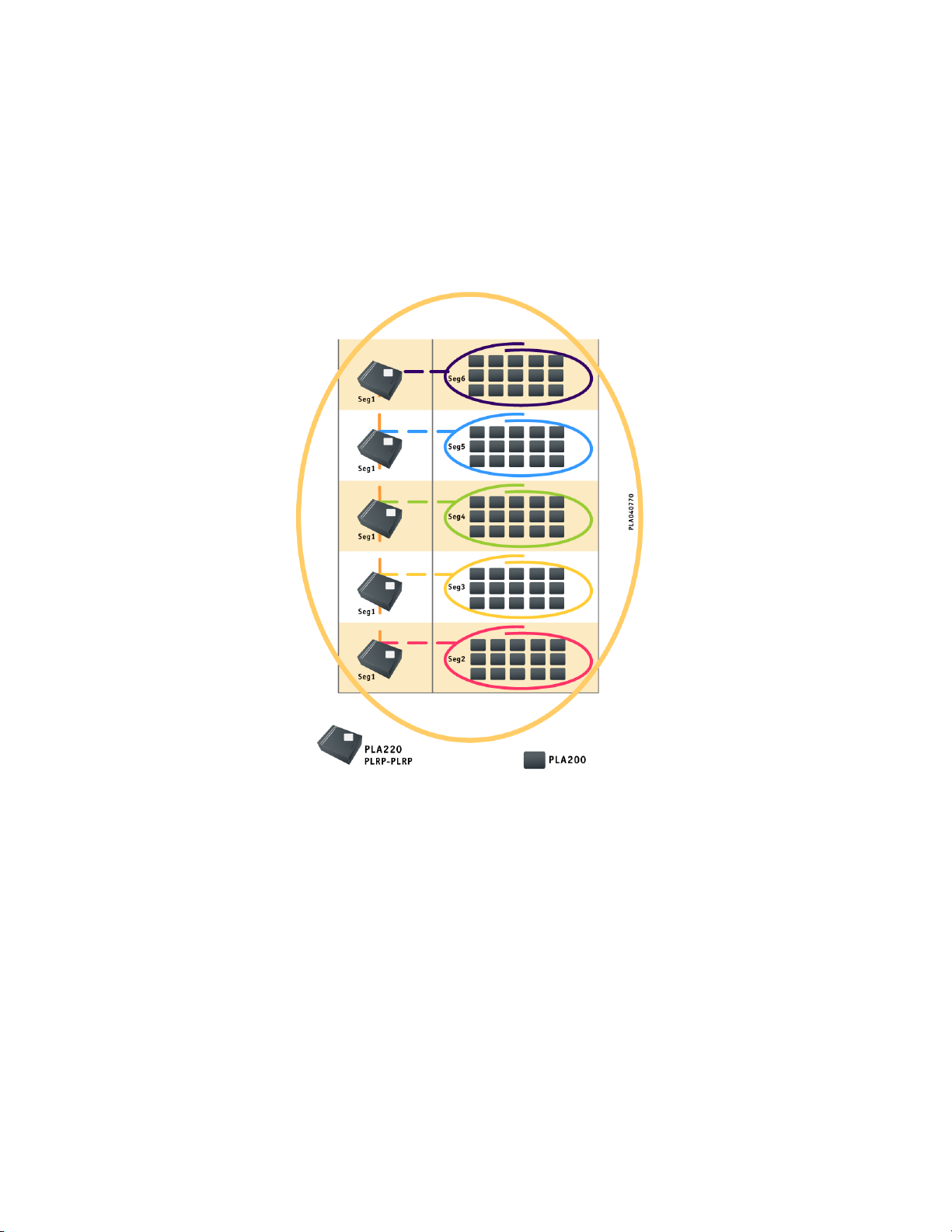
system.
The power system is an environment subject to varying levels of interference. The distance between outlets, the number of connections and the load are very hard to predict. To optimise this
media, Oxance has designed devices using PowerPacketTMtechnology, developed by IntellonTM.
This technology is the basis for the HomePlugTMspecification.
PowerPacketTMoperates with OFDM (Orthogonal Frequency Division Multiplexing) modulation
that is used in digital terrestrial television and the 802.11a standard. OFDM is a broadband wireless transmission technology capable of overcoming obstacles on the transmit-receive system.
OFDM solves the problem of transmitter-receiver alignment. For a very fast broadband connection (several megabits per second), the transmitter and the receiver must be perfectly aligned
which is rarely the case in an urban environment where there are many buildings. With OFDM
devices, this is not a problem, since the system transmits a signal on several frequencies at once.
Even if only one weak signal passes, the receiver can reconstruct the message, regardless of any
obstacles encountered on the other frequencies.
The protocol used is CSMA/CA (Carrier Sense Multiple Access with Collision Avoidance), similar
to 802.11, as well as priority classes and latency control. The frequency bandwidths range from
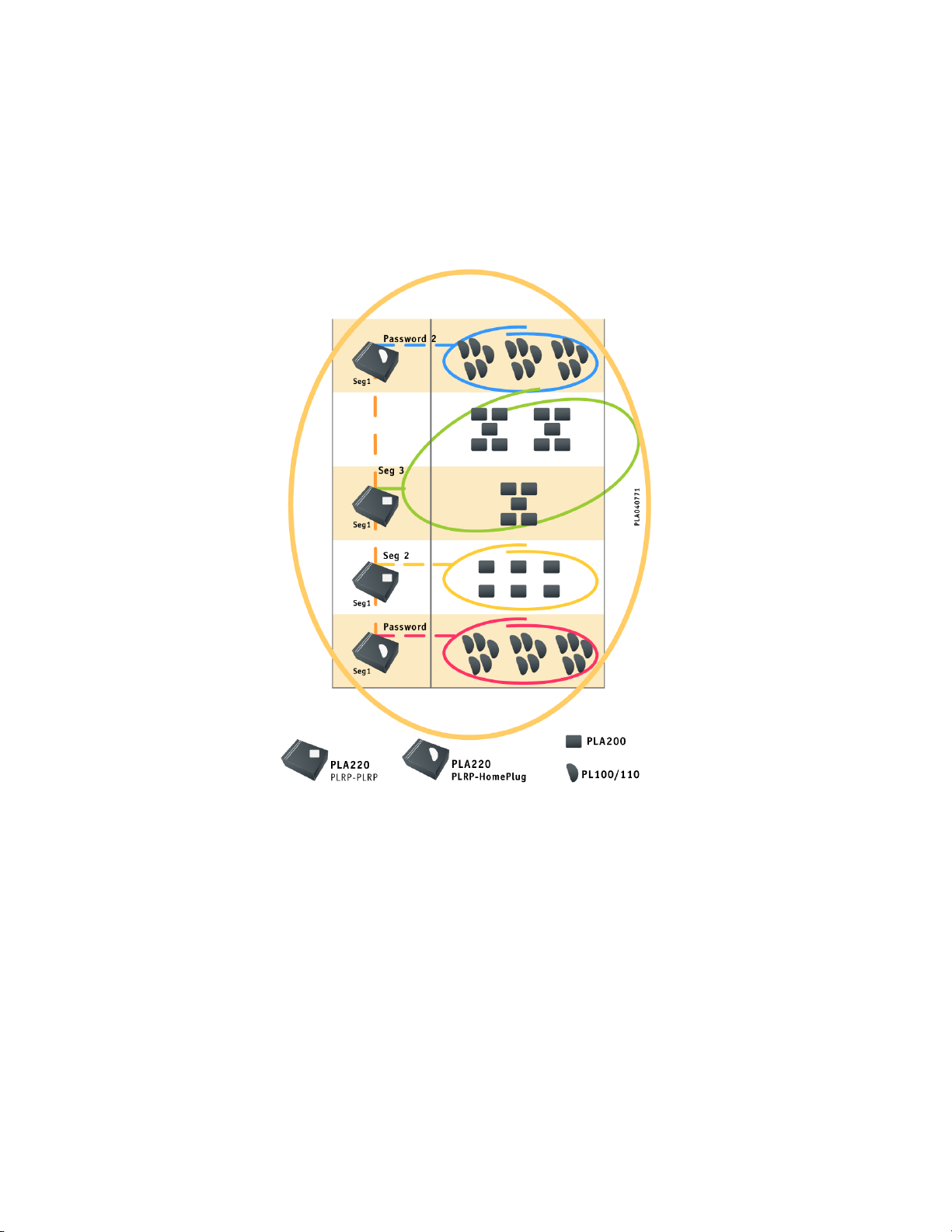
4.3 Mhz to 20.9 Mhz for a transfer rate of 14 Mb/s, or roughly 6 Mb/s effective data rate.
The communication distances are approximately 200 m, with the communication distance and
the transfer rate theoretically proportional to the SNR (Signal to Noise Ration) and dependant on
the quality of the network connections. Anything that reduces the SNR (switching power supplies,
halogen lamps, dimmer switches, etc.) or that modifies the impedance of the network (extension
cords, power strips, etc.) is likely to decrease the communication distances and/or the transfer
rates.
PowerPacketTMadjusts the transmission rates and times by forcing segmentation of frames that
exceed a certain duration to provide the best quality of service (QoS). The PowerPacketTMprivacy
mechanism creates a logical network in which all stations share a common encryption key.
A 56-bit DES algorithm encrypts each frame. By using several different keys, several secure, in-
dependent logical networks can be created.
On the three-phase network, the high frequency coupling of the phases in the input cable may
be sufficient to allow PLCnetTMunits plugged into different phases to communicate with each
other. For systems with long wiring or a band-stop filter, we recommend installing an Oxance
capacitive coupler (CPL3PH) for better performance.
Page 6
3 THE MOST COMMON ARCHITECTURES 6
3 The Most Common Architectures
Multiple combinations are possible. Below we provide a few concrete examples.
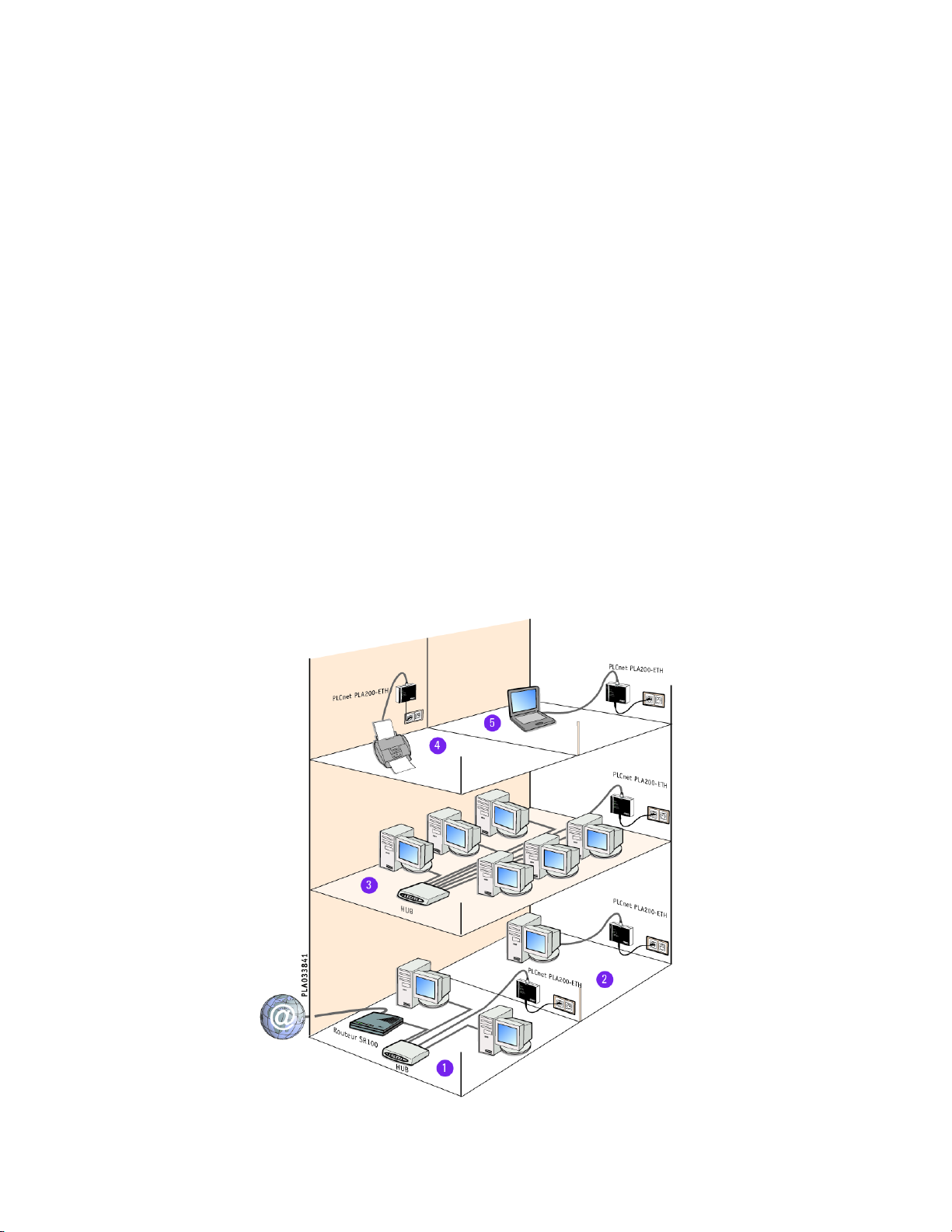
3.1 Your business network via electrical outlets.
(1) Your DSL internet access is limited to one computer or located in just one
room : Connect a PLA200 to the Hub/Switch where the router is plugged in and you
have instant, simultaneous internet access for all the computers in your company.
(2) and (5) Some rooms in your company are not wired to the Ethernet network :
Connect your computers to the powerline network via the PLA200 units, and access all
network applications, shared files, and the Internet.
(3) You need to connect an Ethernet network room to the other floors in your
company : Plug in a PLA200 to the Hub/Switch and access all of the other PLA200s
(computer, router, printer, etc.).
(4) You need to isolate a noisy machine to improve working conditions : Connect
a PLA200 to your photocopier, printer, or other Ethernet unit and place it in an out-ofthe-way location.
Page 7
3 THE MOST COMMON ARCHITECTURES 7
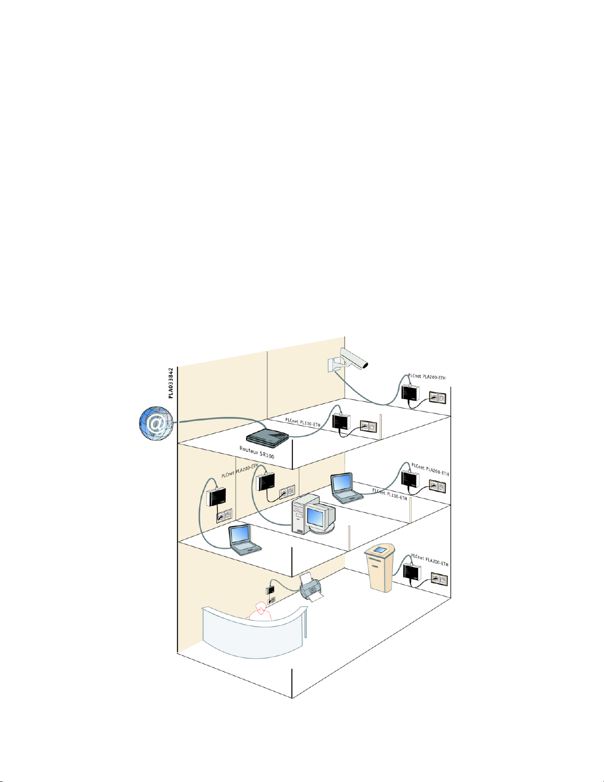
3.2 Schools, government office, museums, hotels
(1) Your lobby is not connected to the computer network :
Connect a PLA200 to a multimedia terminal and get all the benefits of a network (company presentation, free internet access).
(2) You have many rooms that are not wired or do not need Ethernet access at all
times :
As the need arises, plug in the PLA200 to get an instant access point (hotel rooms,
offices, training rooms, etc.)
(3) You want to control a location or monitor a parking lot or sensitive are at a
lower cost :
Connect the PLA200 to an Ethernet-enabled video camera and you can conduct your
video-surveillance over the powerline.
Page 8
3 THE MOST COMMON ARCHITECTURES 8
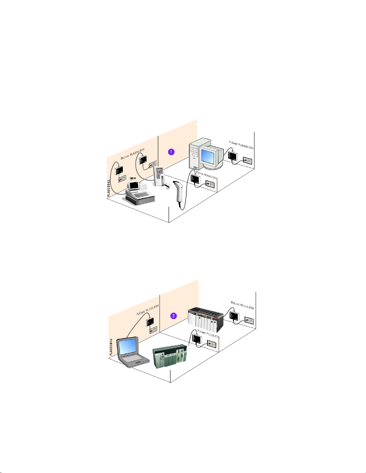
3.3 Industries, services, stores
(1) You want to add or move a point of sale in your store :
Connect the PLA 200 to your cash register, bar code reader or payment system and you
have an instant network with no special wiring.
(2) You want to control industrial equipment via the Ethernet network (controllers, sensors, maintenance systems, access control, etc.) :
Connect the PLA200 to your unit and place it where you want, without wiring or rewiring.
Page 9
4 THE ADVANCED FEATURES OF THE PLA200 9
4 The Advanced Features of the PLA200
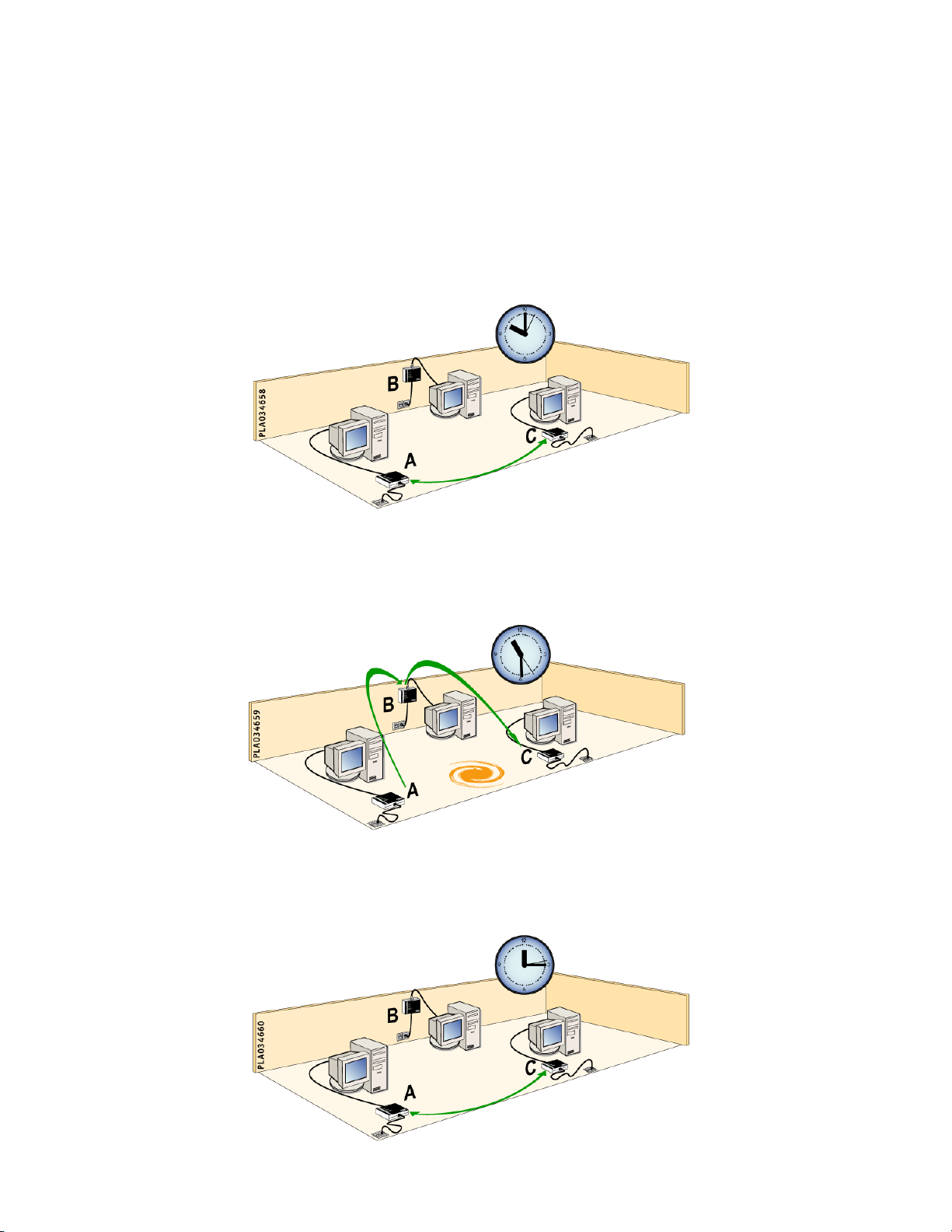
4.1 Dynamic Routing (selecting the best route)
• At 10 :00 AM : Communication between A and C is direct ; there is no interference.
• At 11 :30 AM : Electrical interference between A and C results in lower performance.
The data is automatically relayed via B in order to optimise transmission rates.
• At 12 :15 AM : The electrical interference is resolved and direct communication is
once again the best choice, so the relay via B is eliminated.
Page 10
4 THE ADVANCED FEATURES OF THE PLA200 10
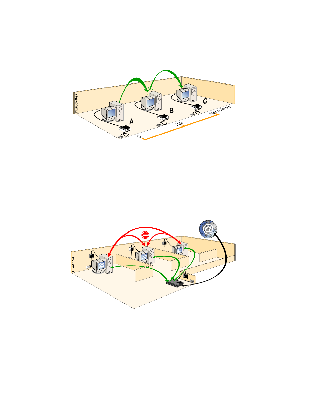
4.2 Automatic Repeater (improving distances)
Example of the relay feature : PLA200s A and C are too far apart to be able to communicate with each other. PLA200 B is automatically used as a relay to create a connection
between A and C.
4.3 MAC Address Filtering
You can restrict data traffic on the Ethernet network.
The principle is similar to a firewall, in which the data are filtered between a source and
a destination.
Example :
All of the rooms in a hotel have internet access, but for security reasons, access between
the rooms is impossible.
Page 11
4 THE ADVANCED FEATURES OF THE PLA200 11
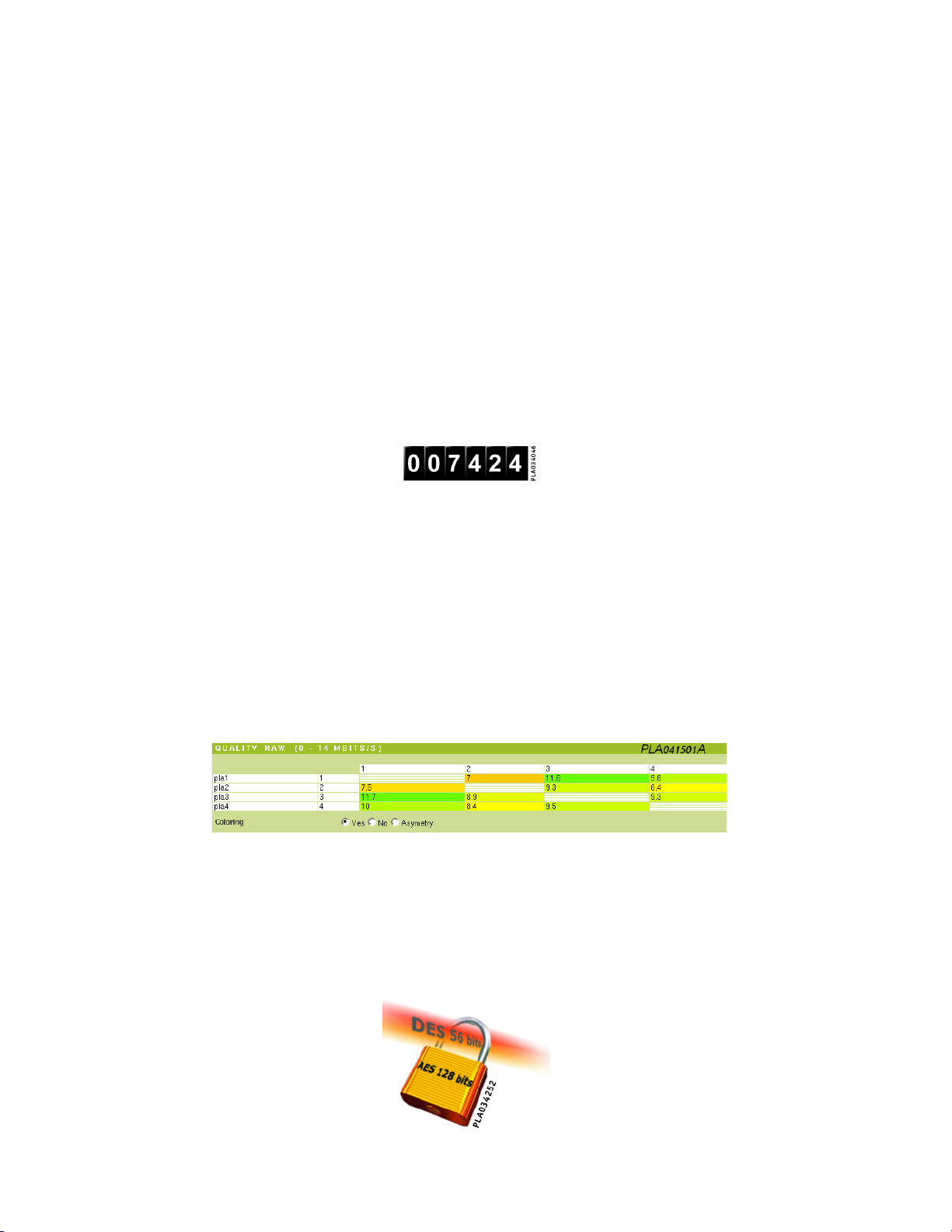
4.4 Managing Bandwidth
Since the bandwidth on the powerline network is not infinite, it may be wise to limit
communications between the PLA200s.
Incoming or outgoing bandwidth can be limited (in kbits/sec) via the Ethernet connection.
Example :
In a hotel, you want to distribute high-speed internet access evenly.
So you limit the bandwidth for each room.
4.5 Communications Counter (kbytes)
For statistics or invoicing purposes, you can count the number of bytes sent and received by the PLA200s. The counters are saved to flash memory and can be reset only
by the administrator. Just plugging in or unplugging the PLA200 does not r eset the
counters.
4.6 Complete information about the status of the powerline network (best routes, noise, network quality)
The powerline network status is analysed in real time. Colour graphs show information
on quality and interference for quick and easy diagnostics.
4.7 DES 56 bit and AES 128 bit Security Protocols
By default, data transmitted over the powerline network are DES 56 bit encrypted.
For sensitive networks, security can be reinforced by activating the AES 128 bit protocol
on top of the HomePlug DES 56 bit encryption.
Page 12
4 THE ADVANCED FEATURES OF THE PLA200 12
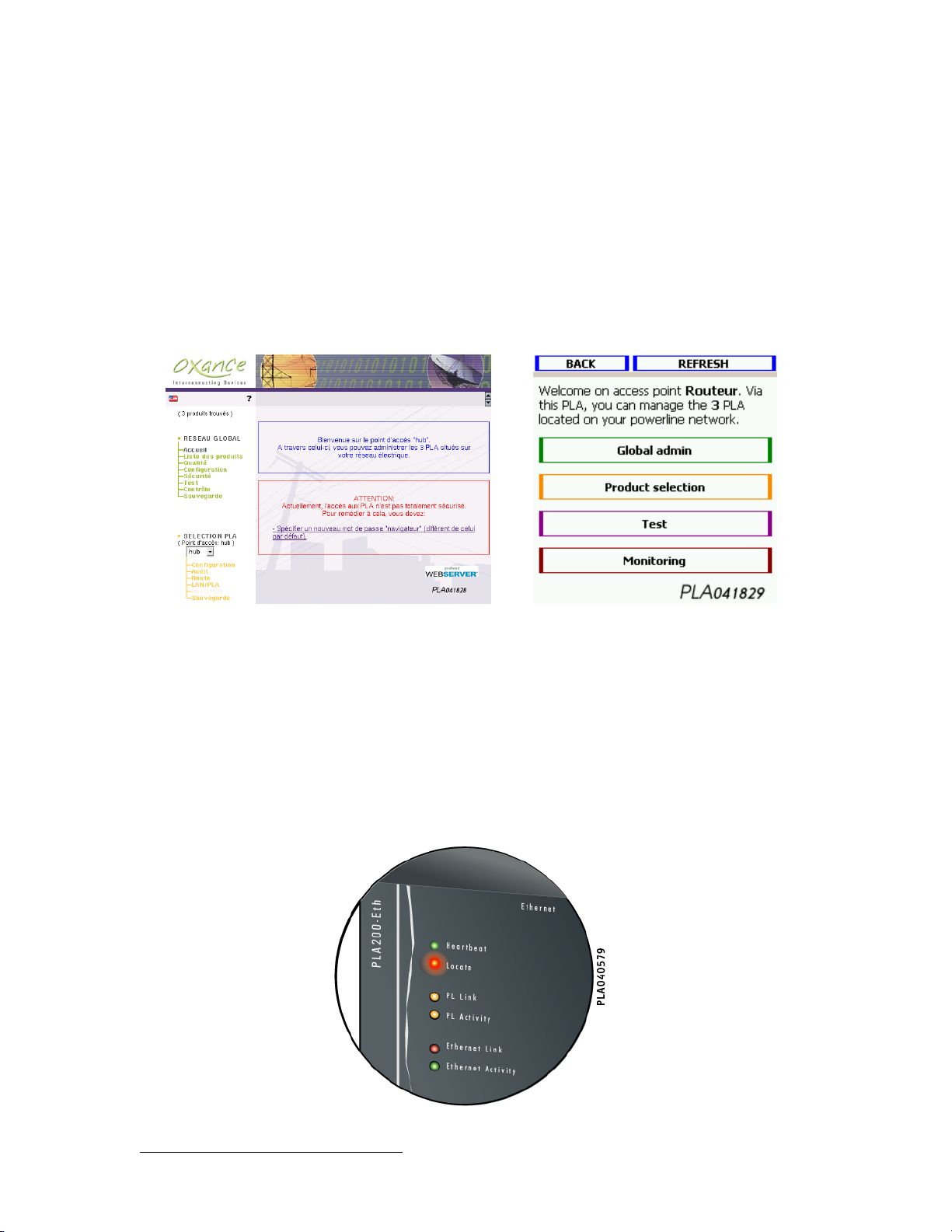
4.8 Configuration by HTTP Server
The PLA200s can be fully administered via a Web interface.
No external software is needed (no need to install software on your computer), you
already have the software you need to administer the system a web browser such as
Internet Explorer 61or Mozilla 1_4. You can also setup and manage your Powerline
Network with a PocketPC.
Computer PocketPC
4.9 SNMP V1, V2, and V3 Agent with Trap Control
This protocol allows you to manage the PLA200s using management utilities such as
HP-OpenView, etc.
4.10 Locating a Remote PLA200
It is possible to locate the remote device by activating the flashing Locate light.
1
Internet ExplorerTMis a registered trademark of Microsoft Corporation.
Page 13
5 PRODUCT PRESENT ATION 13
5 Product Presentation
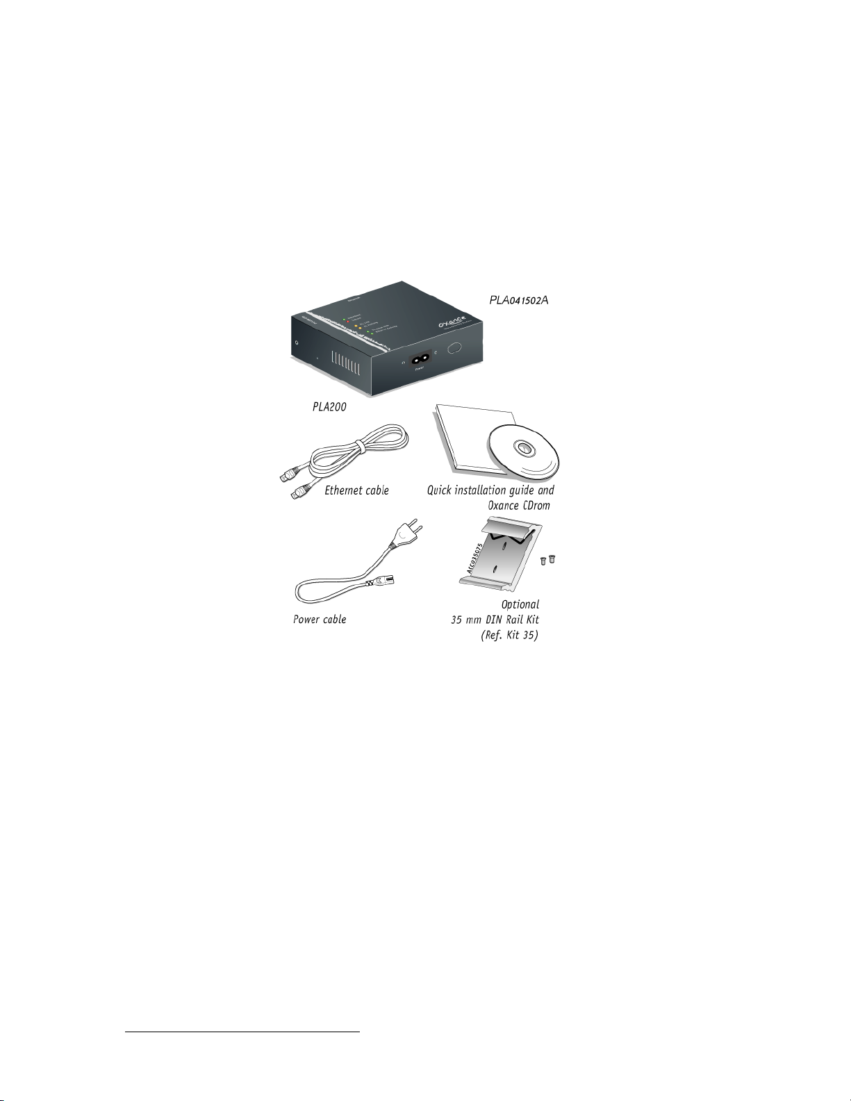
5.1 Package Contents
Check that the package contains the following items.
If any of the items is missing, contact your dealer.
5.2 Required Configuration
Any Ethernet-enabled device (computer, controller, cash register, card reader, video/webcam,
router, terminal server, etc.).
To configure and set up a PLA200:
● 1 computer with network card and TCP/IC protocol configured.
● 1 web browser
2
The web browsers are included on the Oxance CD ROM.
2
(Internet Explorer 6.0.28 minimum or Mozilla)
Page 14
5 PRODUCT PRESENT ATION 14
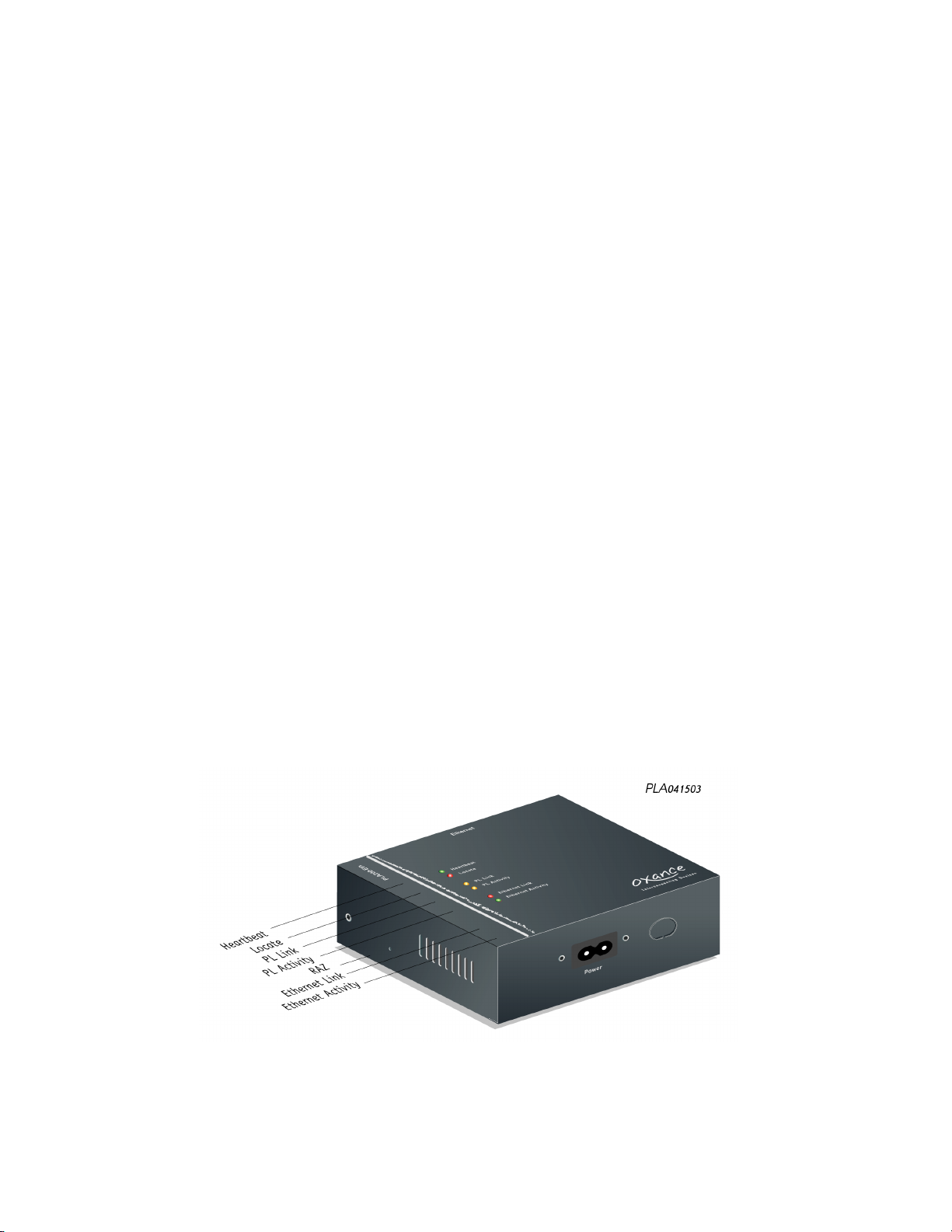
5.3 Description of the Device
5.3.1 Lights
Heartbeat
Green flashing light (flashes every second) : The PLA200 is powered on and operating
correctly.
Locate
Red : The light flashes during a restart or when the user wants to physically locate a
device via the HTML interface.
PLA Link
Orange : The PLA200 indicates the presence of another HomePlug device on the powerline network.
PLA activity
Flashing Orange : The PLA200 is receiving or transmitting data over the powerline network.
Ethernet Link
Green : The PLA200 is connected to an Ethernet-enabled device.
Ethernet activity
Flashing green: The PLA200 is receiving or transmitting data over the Ethernet network.
Reset (Reset Factory Config)
Reset : press the button until the red Locate light flashes to reset to factory configuration.
Page 15
5 PRODUCT PRESENT ATION 15
5.4 Features and Recommendations
• The PLA200 can relay the signal and transmit over long distances (repeater function)
only if each PLA200 is no farther than 200 meters away from the next closest PLA200.
The repeater function is automatic and does not required any special configuration.
• If you have more than 15 PLAs on the same network, performance may be affected. To
achieve a balanced network, you need to work with groups of 15 devices. Each group
is linked to the others by PLA Bridges (see explanation and configuration on page 51)
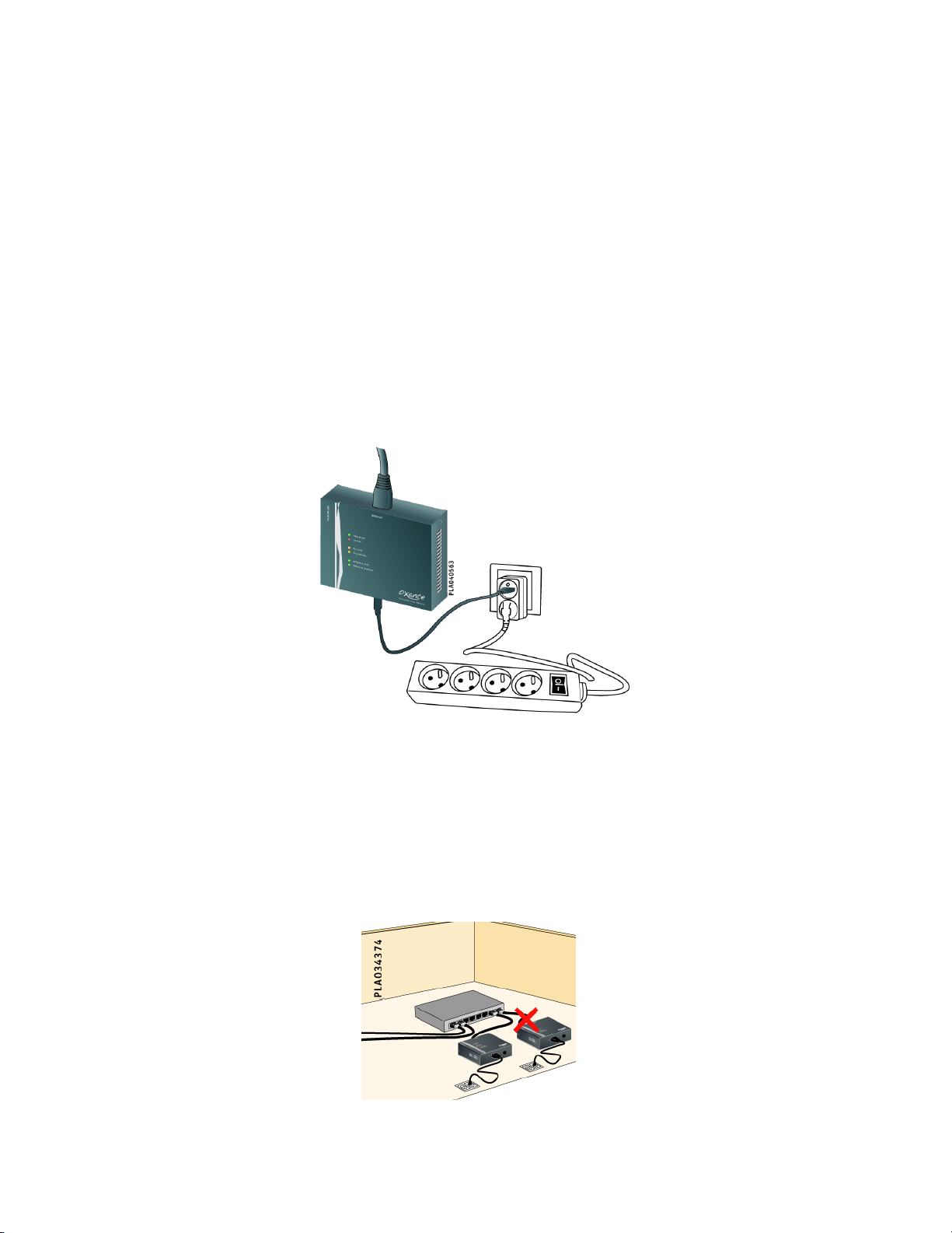
• Whenever possible, use one PLA 200 adaptor per wall outlet. If this is not possible,
use a single-to-double T -shaped adaptor and plug in your PLA200 and your power strip.
• You must use the 30 cm power cord provided, since a longer cord will affect the
powerline network performance.
• Never plug the PLA200 into a lightning or surge protector, as these devices filter out
certain frequencies and affect the performance of our products.
• Never connect several PLA200s on the same Hub/Switch, as this can create loops and
prevent the powerline network from operating.
Page 16
6 INSTALLING THE PLA200 16
6 Installing the PLA200
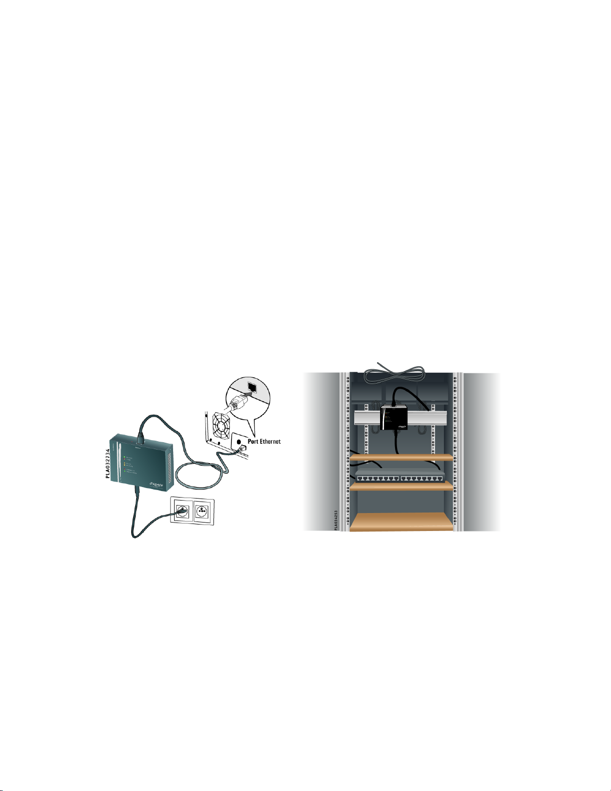
The PLA200 Ethernet adaptor enables you to connect any Ethernet device (computer,
router, controller, card payment system, video/webcam, network printer, etc.)
No driver or special configuration is required to use the PLA200.
Advanced configuration (security, filtering, analysis) is done using a common web browser.
● Plug in the PLA Ethernet adaptor to an electrical outlet.
● Connect the Ethernet cable to the PLA200 and to the Ethernet interface on your
device or to your Ethernet Hub/Switch.
The auto MDI/MDIX function simplifies the installation process in that there is
no need to worry about what type of cable to use (straight-through or crossover).
The port adjusts automatically to the peripheral (Hub/Switch or devices) to ensure a good connection without manual intervention.
Page 17
7 CONFIGURING THE IP ADDRESS 17
7 Configuring the IP address
7.1 New Network or Existing Network
To configure a PLA 200, you must connect to its IP address from a web browser. By
default, PLA200s have IP address 192.168.1.251 and are in automatic IP mode.
New Network or Unknown MAC
address
Factory-default IP
– Simply assign you computer a Class
C network IP address. For example :
192.168.1.1l
– You can then directly access the
PLA200 via your browser by entering
192.168.1.251 in the address bar.
Existing network
Automatic IP address
“auto_ip”
– Auto_ip mode assigns a network IP
address based on the MAC address.
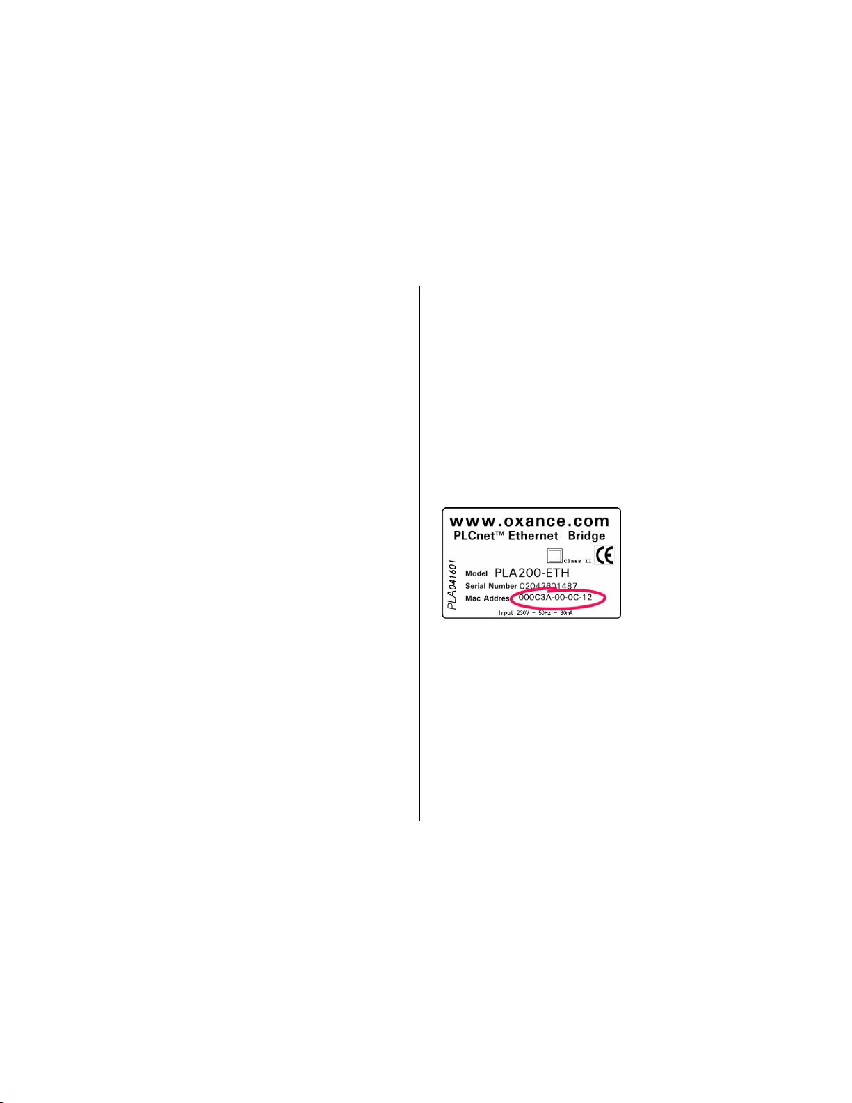
– Find the MAC address of your
PLA200 printed on the label, starting with : 00-0c-3a
– This MAC address must be linked
on the computer to the selected free
IP address (add a static entry in the
ARP table).
– C :\> arp -s [IP adress] [MAC adress]
– The ICMP protocol (ping) is then
used to supply the IP address to the
PLA200.
– C :\> ping [IP adress]
Once the PLA200 is accessible via your browser, you can access the other PLA200s
through the power system to configure your powerline network.
F To keep the IP address, you have to enter it again on the graphic interface
of the PLA200 (see page 30 “Global Network - Setup - Network”).
Page 18

7 CONFIGURING THE IP ADDRESS 18
7.2 Example of IP address assignment (auto_ip mode)
Existing Configuration :
A Windows 2000 computer with Ethernet card and TCP/IP protocol installed and configured. A Class C Network (for example: 192.168.1.0/255.255.255.0)
F You must have administrator privileges on the computer and be able to add an
ARP entry, otherwise you will receive an error message such as: "The ARP entry
addition failed".
1. Connect the PLA200 on your Ethernet network or directly to your computer.
2. Determine which free IP address you want to assign to the PLA200 (for example:192.168.1.200)
3. Identify the MAC address of the PLA200 (for example: 00-0C-3A-01-01-01)
4. Open the command prompt (Start - Run - Cmd)
5. Add a static entry in the ARP table of your Windows 2000:
C:\> arp -s 192.168.1.200 00-0C-3A-01-01-01
6. Run the "ping" command on the free IP address
C:\> ping 192.168.1.200
7. As of the second request, the PLA200 is configured and should respond.
You can now enter this IP address in a web browser to access and configure the PLA200.
8. Once the IP address is assigned, remember to set the IP address in the HTML configuration
and disable the auto_ip mode : "Global network - Setup - Network" page 30.
Page 19
8 GRAPHIC CONFIGURATION 19
8 Graphic Configuration
8.1 Home Page
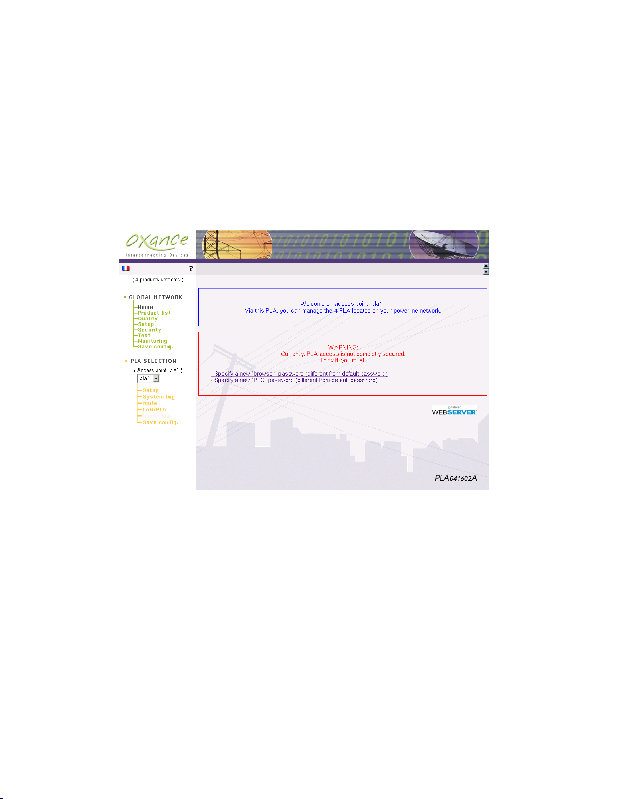
Once the IP address is assigned to your PLA200, you can access it from a web browser.
Enter the IP address of the PLA200 in the address bar of Internet Explorer 6 or Mozilla
1.4)
The device’s Home page comes up :
No authentication is required for the first connection. However, you must change the
default passwords for the PLA200, to make your network secure.
Browser password : This password authenticates you on the PLA’s web server. This
password is also used as an authentication key and encryption key for SNMPv3 requests.
Once the password has been modified, authentication is needed to access the Web
server. The user login is "admin" in lower case.
PLC password : This is the encryption key used by all of the PLAs present on the power
system.
F The passwords must be between 8 and 16 alphanumerical characters in length.
Until your passwords are changed and saved, a warning message will appear each
time you connect.
Page 20
8 GRAPHIC CONFIGURATION 20
You can access detailed online help about the current page at any time by clicking on
the question mark (?).
Click on the flag to switch the configuration interface to English.
To update all the fields, you have to close and re-open you br owser, or refresh the page
by clicking on refresh or update in your browser).
Page 21

8 GRAPHIC CONFIGURATION 21
GLOBAL NETWORK (pages with green background)
The following menus have to do with all of the PLA200s detected on the powerline network :
Home - Return to the home page
Products list - Displays the PLA200s present on the
powerline network.
Quality - Graph (colour graph) of the quality between all
of the PLA200s.
Setup - Manage passwords, update firmware and display
advanced pages
Test - estimate the real bandwith (Mb/s) beetwen the
Access point and another remote PL by transfering large
amount of data.
Monitoring - graphically control the quality change
beetwen 2 PLA.
Security - Data filtering, limiting bandwidth and optional
byte count.
Save Config - The settings of all the PLA200s are saved to
flash memory.
PLA SELECTION (pages with orange background)
The following menus are directly related to the selected PLA200 :
Access Point : This is the name of the access point PLA, which connects to your computer via
Ethernet.
Select PLA200 to configure : The PLA are listed in alphabetical order and the access point is
automatically selected.
Setup - View and set the IP address, name and location of
the PLA200.
System log - Configuration of the event log.
Route - Routing table between the PLA200 selected and
the others present on the powerline network (direct link or
optimised link via relays).
LAN/PLA - MAC address table detected around the
PLA200.
HomePlug - Configuration of PLCnet with PLA Bridges
(available only for PLA Bridges).
Save Config - The settings of the selected PLA200 are saved to flash memory.
Page 22
8 GRAPHIC CONFIGURATION 22
8.2 Global Network
8.2.1 Global Network - Products List
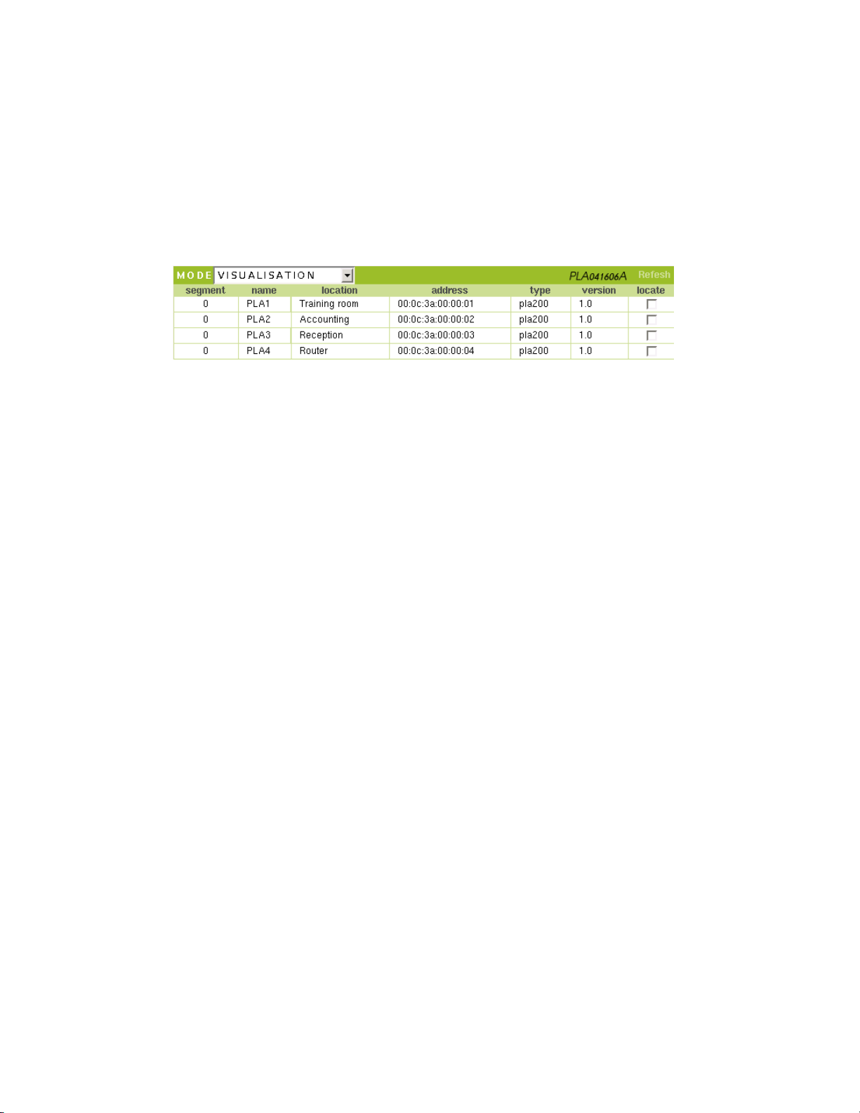
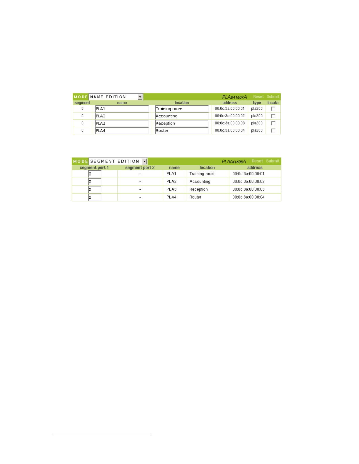
LIST OF DEVICES DETECTED ON THE POWERLINE NETWORK
• segment : segments the PLA networks. Caution, this parameter should be used only
if you have a PLA Bridge (see page 51).
• name : this field is composed of the last three bytes of the device’s MAC address
preceded by "pla_". It can be customized and may contain alphanumerical characters
(32 characters maximum).
• location : this field can be customized and may contain alphanumerical characters
(32 characters maximum).
• address : this is the MAC (Media Access Control) address of the PLA200, 6-byte hex
coded.
The first three characters are reserved for the manufacturer (00:0c:3a for Oxance).
The next three are digits from 0 to 9 or letters from A to F. This alphanumeric string is
unique and is used to identify the PLA200.
• type : the type of PLA (PLA200, PLA220, etc.)
• version : the version of the PLA’s internal software.
• locate : when you click on this box, the Locate LED on your PLA200 will flash. This
enables you to quickly find the physical location of your device.
By default, the VISUALISATION (VIEW) mode is selected, and cannot be modified. To
refresh the list of devices detected, click "Refresh"
Page 23
8 GRAPHIC CONFIGURATION 23
To modify and personalize the fields, select: NAME EDITION :
• NAME EDITION
• SEGMENT EDITION3.
3
Segment edition should be used only if you have a PLA Bridge (see page 51).
Page 24

8 GRAPHIC CONFIGURATION 24
8.2.2 Global Network - Quality
The quality chart shows a global view of the network quality. It is read line by line, from
left to right, and displays a value and colour for each PLA200 pair analysed.
Quality can be displayed in 4 modes :
● raw mode (powerline estimate between 1 and 14 Mbps by default)
● tcp mode (TCP estimate between 1 and 5.8 Mbps)
● internal mode (internal value between 1 and 253)
● % mode (percentage of bandwith)
The unit of quality can be set in “Global Network - Setup” page 27 .
This value is represented by a colour scale going from red (poor) to yellow (average) to
green (excellent).
The letter R corresponds to ROBO mode. In this mode, the data are transmitted at very
low speed (roughly 1 MB/s). This mode is used in two cases:
● R on a white background: The quality of the line was determined to be very bad, but the
transmission is still possible.
● R on a grey background: The quality of the line could not be determined, but the transmis-
sion is still possible.
If the devices cannot communicate, no value is displayed.
Note: This chart shows the direct quality between each PLA. This quality should be
compared to the bandwidth likely to be obtained if the data took a direct route.
If the direct quality is bad or if direct routing is impossible, the PLA calculates the best
route to take (using intermediate PLAs as relays) in order to optimise bandwidth and
enable 2 PLAs that cannot see each other to communicate
Coloring : Yes/No/Asymmetry
Yes : provides a quick estimate of the communication qualities via a colour scale.
No : Disables the colours on the chart. This may facilitate printing.
Asymmetry : highlights asymmetry.
Page 25
8 GRAPHIC CONFIGURATION 25
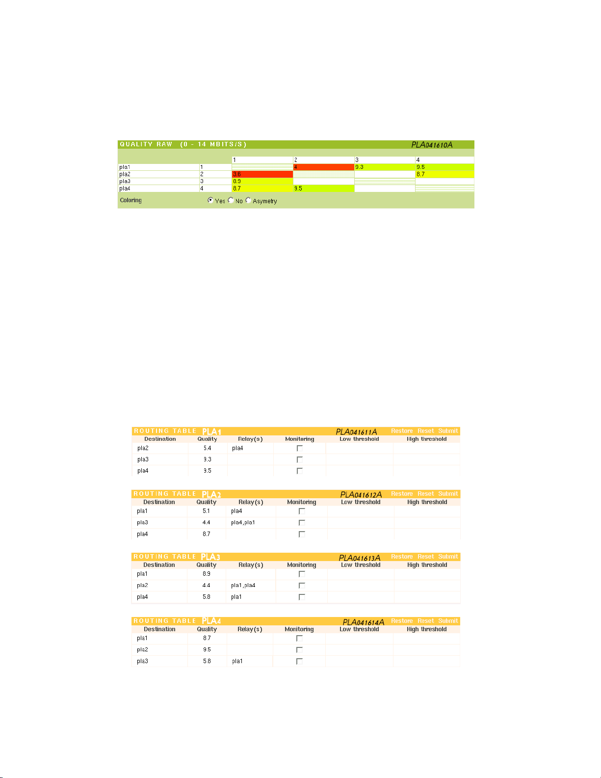
Interpreting a chart with relays
PLA1 sees PLA2, PLA3 and PLA4
PLA2 sees PLA1 and PLA4
PLA3 sees PLA1
PLA4 sees PLA1 and PLA2
You can see that the qualities between PLA1 and PLA2 are mediocre.
It seems that PLA1 and PLA2 are too far apart on the power system to establish a good
quality communication. However, the protocol will optimise the communication by using PLA4 as a relay.
PLA3 cannot communicate directly with PLA2 and PLA4 (too far apart), so it must use
a relay (PLA1).
This interpretation can be checked by viewing the routing table for each PLA200 "PLA
Selection - route".
Page 26
8 GRAPHIC CONFIGURATION 26
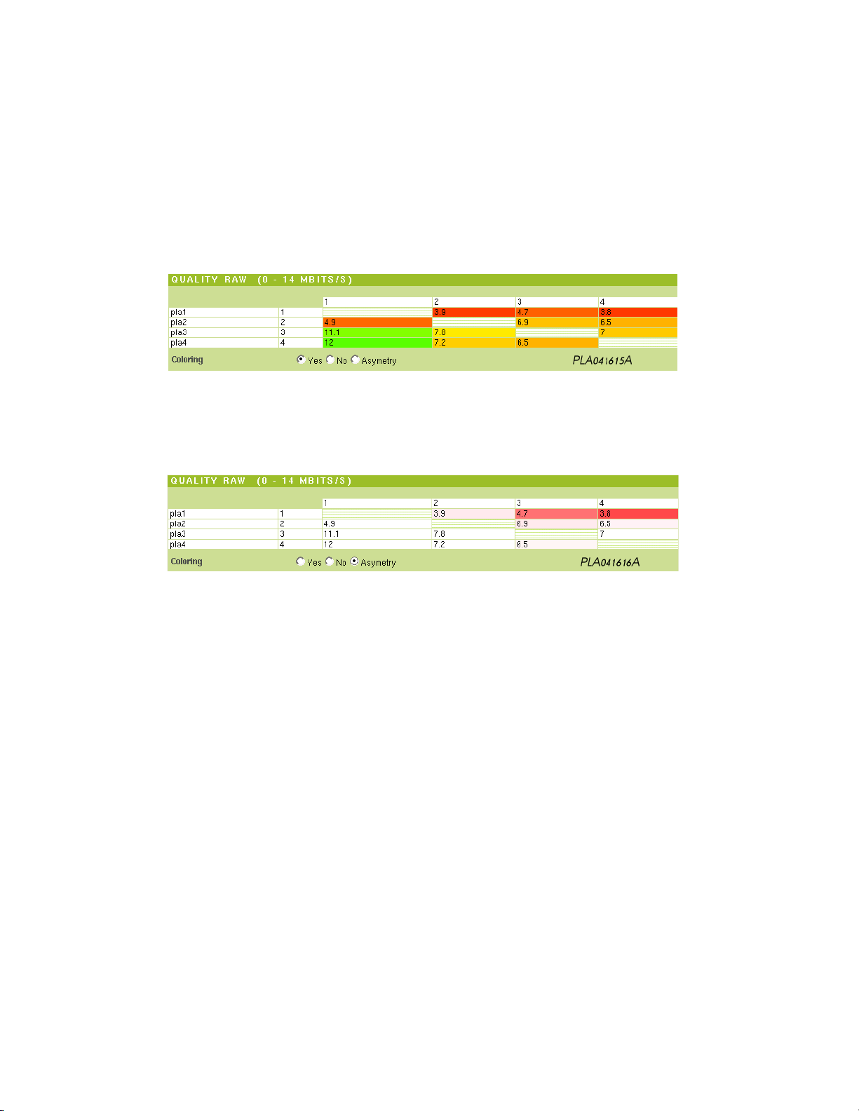
Interpreting a chart with asymmetry
By the very nature of the power system, the communication quality between two
powerline devices is asymmetrical in transmit and receive.
Identical or similar quality rates indicate optimum quality, whereas a large discrepancy
indicates electrical interference.
This chart shows a problem on PLA1 and questions about PLA2. By clicking on asymmetry, you highlight the data rate differences between the PLA200s, shown on a red
colour scale.
The red on the PLA1 line confirms the first diagnosis: PLA1 is experiencing electrical
interference. However, PLA2 is not involved in the problem, since there is no colour on
its line.
Page 27
8 GRAPHIC CONFIGURATION 27
8.2.3 Global Network - Setup
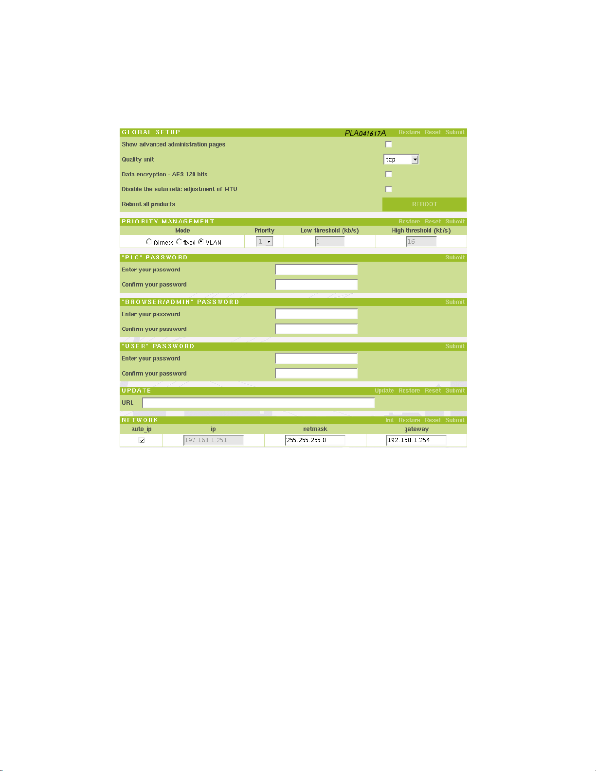
GLOBAL SETUP
• Show advanced administration pages : by checking this box and refreshing your
browser, you get three additional sections in the "PLA Selection" Quality, Local Quality
and Register.
You should use these pages only if so requested by the Hotline service. They can be
used to check your diagnosis.
• Quality Unit : Select the unit for representing the values (charts, routes, etc.)
raw: Powerline estimate between 1 and 14 Mbps
tcp: TCP estimate between 1 and 5.8 Mbps
internal: Internal value between 1 and 253
%: Percentage of bandwidth
• Data encryption - AES 128 bits : By default, data transmitted over the powerline
network are DES 56 bit encrypted. You can increase the level of security by using AES
128 bit encryption to encrypt your data before transferring them over the powerline
network.
Caution: Enabling AES 128-bit encryption considerably diminishes the powerline performance.
Page 28

8 GRAPHIC CONFIGURATION 28
• Disable the automatic adjustment of MTU : if a PLA receives TCP packets with
MTU greater than 1460 bytes via the Ethernet network, it adjusts the MSS (Maximum
Segment Size) to avoid fragmentation. This setting is enabled by default, and can be
disabled from this window for all of the PLAs in the network.
• Reboot all products : Remember to save your changes before restarting the PLAs.
PRIORITY MANAGEMENT
In order to optimise the network, you can change the priority management.
Priorities can be setup in 3 modes :
1 - VLAN : supports VLAN tag 802.1q (by default).
If an Ethernet frame contains a VLAN tag, then the tag priority determine the priority
of the frame when sent on the powerline.
2 - Fixed : fix the priority for frame transmission on the powerline. Normally not use
as a global setup.
To individually change the priority see page 45 PLA selection - Setup - Priority management.
1 low priority
2-3 medium priority
4-5 high priority
3 - Fairness : setup a priority management in relation with throughput.
To improve low data transfer (web, email...) compared to high data transfer (ftp, peer to
peer...), you can setup 2 threshold to determine 3 priority classes.
A low and high threshlod allows to setup the priority level (by default low=1kb/s and
high=16kb/s).
0<data rate<threshold low high priority
threshold low<data rate < threshold high medium priority
data rate > threshold high low priority
"PLC" PASSWORD
The data transmitted between the PLAs are always encrypted using the DES 56 bit
protocol. To work together, the PLAs on your network must all have the same encryption key. By default, all of the devices are shipped with the same encryption key
"oxance.com".
F Changing the encryption key: By changing the encryption key, (PLC password)
you automatically change the encryption keys of all the devices visible on the
powerline network.
Page 29
8 GRAPHIC CONFIGURATION 29
● View all of the PLA200s present on the powerline network (Global network - Prod-
ucts list)
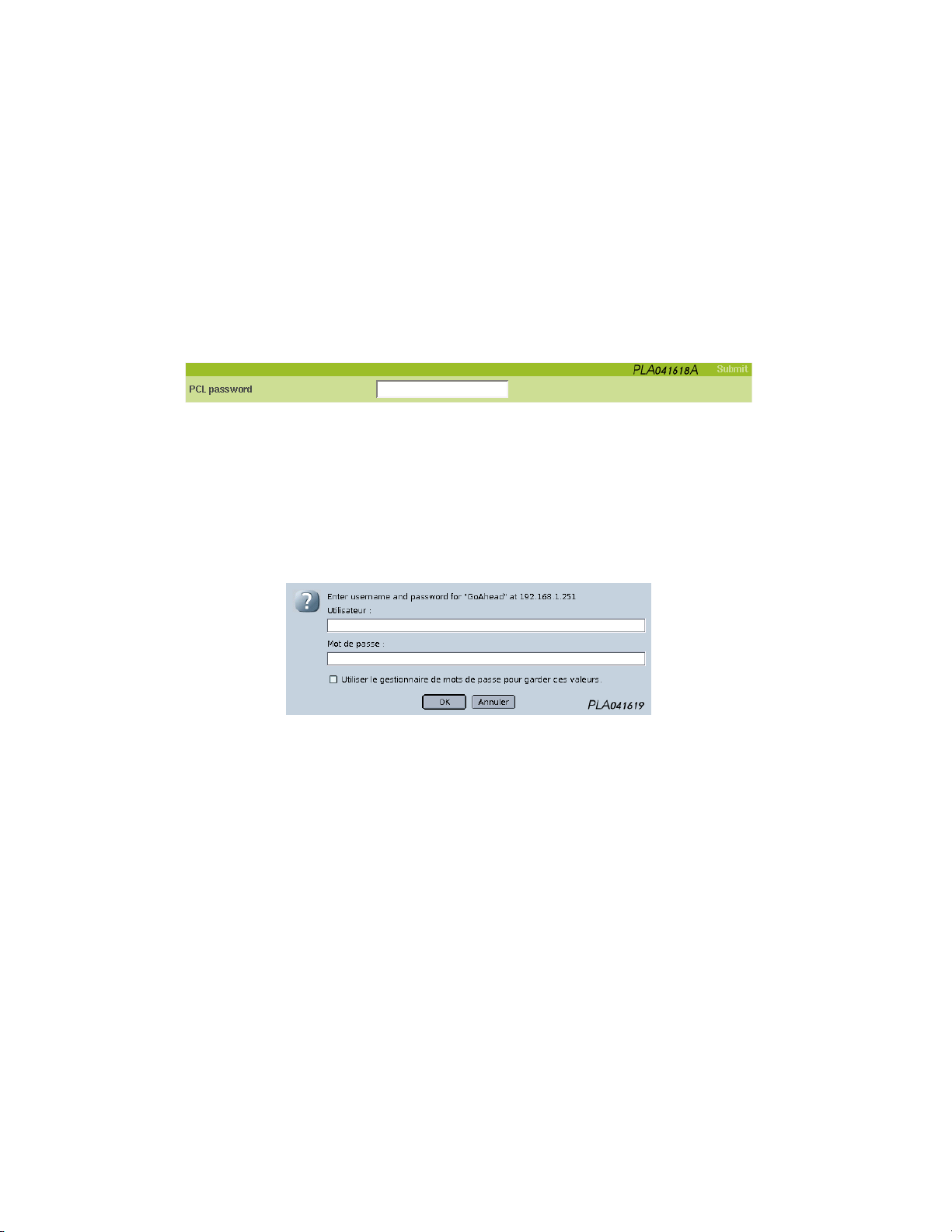
● Modify the encryption key, then validate
● All of the PLA200s are now secure with the new encryption key.
The next time you open your browser or if you refresh the current session, you will be
asked for the PLC encryption key to access the device.
“BROWSER/ADMIN” PASSWORD
This is the password used to connect to the PLA’s HTTP administration server. It is also
used as an authentication and encryption key for SNMPv3 administration requests.
The user name to setup the PLA is "admin" (lower case) and password is “oxance.com”.
Page 30

8 GRAPHIC CONFIGURATION 30
“USER” PASSWORD
The user password is used to make read-only requests in SNMP mode (not implemented
in HTTP mode).
UPDATE
The PLA firmware can easily be updated by indicating the URL address and the name
of the firmware to download.
examples:
● http://adresse_ip_serveur/download/update.hdr
● ftp://login:password@adresse_ip_serveur/download/update.hdr
The complete procedure is described step by step at the end of the manual (see page 68).
NETWORK
This section describes how to configure the PLA IP address for network administration.
• auto_ip : The factory setting for the PLA is auto_ip mode. Auto_ip mode assigns a
network IP address based on the PLA’s MAC address.
Once you have set the IP address and reached the administration pages, you can dis-
able the auto_ip mode.
On the host computer, you must link the PLA’s MAC address with a fr ee IP address:
. arp -s IP_PLA aa:bb:cc:dd:ee:ff (UNIX, MAC)
. arp -s IP_PLA aa-bb-cc-dd-ee-ff (WINDOWS)
Example: . arp -s 192.168.1.251 00:0c:3a:83:00:61
F You must have administrator privileges on the computer and be able to add an
ARP entry, otherwise you will receive an error message such as: "The ARP entry
addition failed".
• ip : We use the term PLA network IP address, since each PLA shares the same ad-
dress. Remember that this IP address is used only for administering the PLAs. When
you "ping" a PLA, only the PLA located on the same Ethernet network as your host
computer will respond. This PLA is your powerline access point, through which you
can setup all of the remote PLAs.
• netmask : Network mask that matches the one used by the host computer.
• gateway : If your host computer is not on the local network, indicate the IP address
of the gateway here.
Page 31
8 GRAPHIC CONFIGURATION 31
8.2.4 Global Network - Security
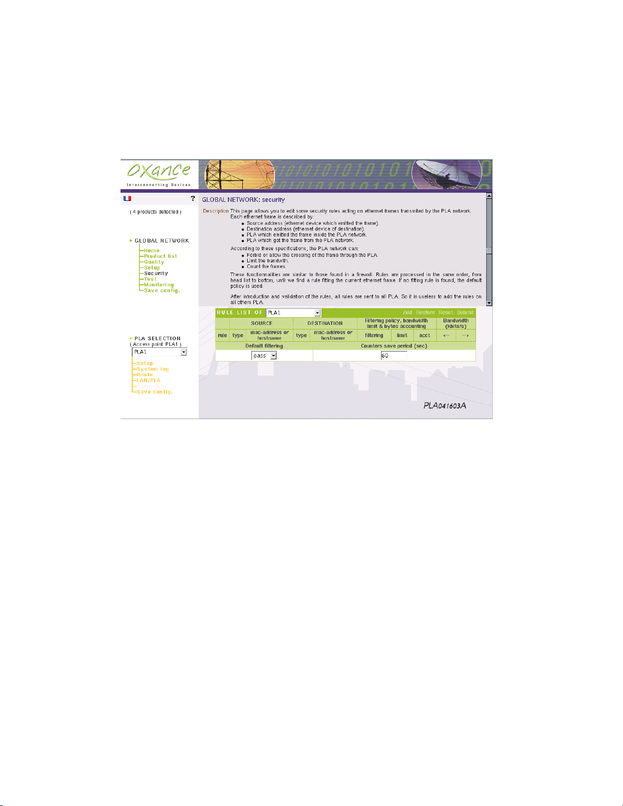
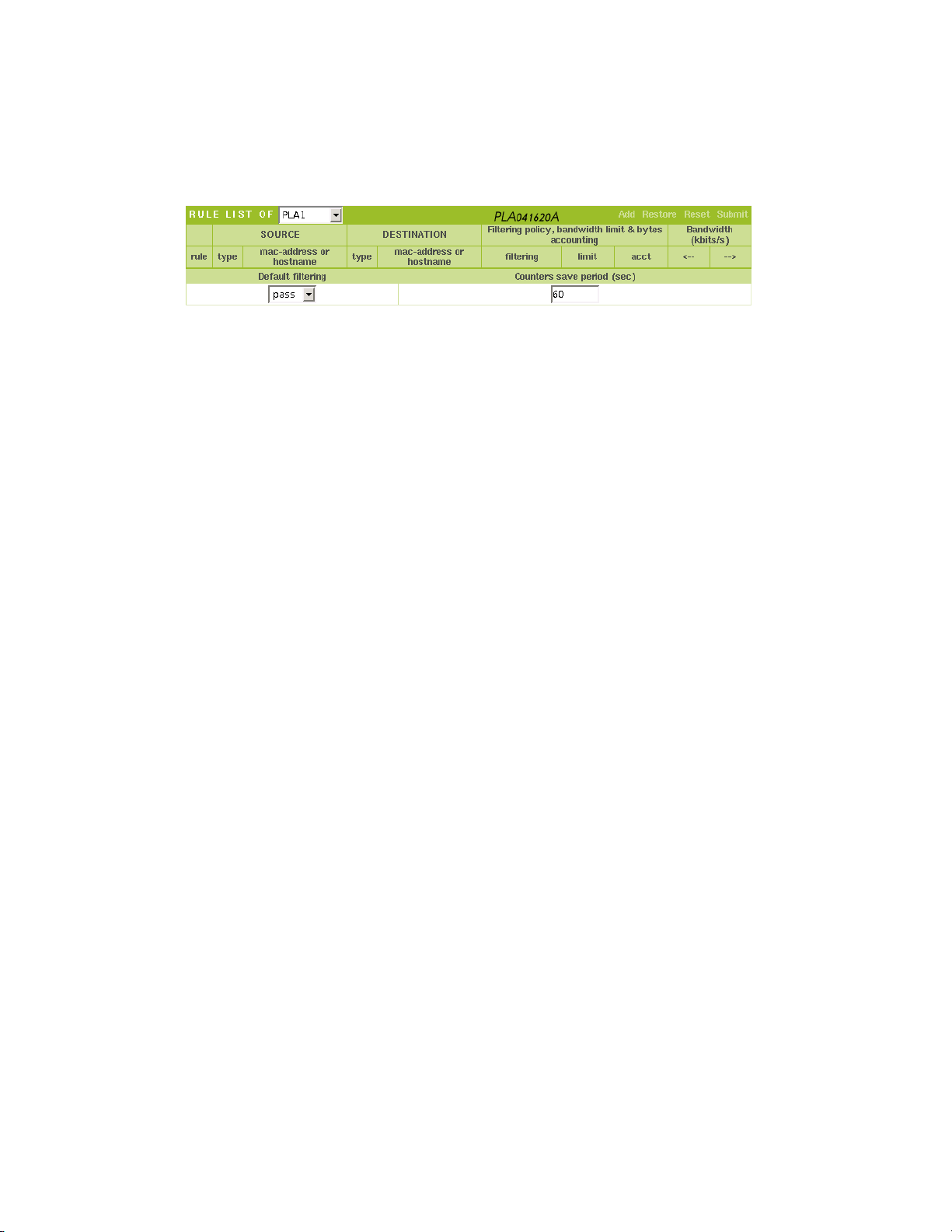
RULES LIST
From this page you can print the operating rules governing the Ethernet frames transported by the PLA network.
Each Ethernet frame has :
• A source address (Ethernet source host that emitted the frame).
• A destination address (Ethernet destination host).
• The PLA that injected the frame into the PLA network.
• The PLA restoring the Ethernet frame.
Based on these characteristics, the PLA network can :
• Deny or authorise transport of the Ethernet frame.
• Limit the bandwidth.
• Count the frames.
This principle is similar to a firewall. The rules are read in order (top to bottom) until a
rule matching the Ethernet frame is encountered. If no matching rules are found, the
system reverts to default behaviour.
F CAUTION: As indicated above, the PLA200 looks for the first rule that matches
the frame. The order in which the rules are entered is very important. Access to
the PLA200 can be interrupted if the rules are entered in the wrong order.
After the rules are entered and validated, they are sent to all of the PLAs.
When a new PLA is added to the powerline network, it does not have any rules. To send
the rules to it, simple select an already configured PLA "RULES LIST OF" and revalidate
the rules.
If the rules are entered incorrectly, (you cannot access the PLA200), you must reset
to factory configuration. Press the Reset button until the red Locate light flashes (see
illustration page 14).
Page 32

8 GRAPHIC CONFIGURATION 32
RULES
Source - Destination
Indicate the source and the destination of the packet and how it is to be processed.
There can be three different types of sources and destination :
*
PLA
LAN
Filtering policy, bandwidth limit and bytes accounting
Filtering
Limit Limit the bandwith in kbits/sec
acct Count the number of kbytes received or sent
Bandwith
<–
–>
Default filtering
All the devices on the network
The name of the PLA selected
The MAC address of a device (computer, router, vi-
deo/webcam, other Ethernet device)
Pass : to set up a pass rule
Stop : to set up a block rule
The bandwidth is limited from the destination to the
source (in kbit/sec)
The bandwidth is limited from the source to the
destination(in kbit/sec)
Pass Let all communications pass.
Block Block all communications.
Page 33

8 GRAPHIC CONFIGURATION 33
FILTER CONFIGURATION
Below we provide step by step examples of several filtering rules.
The following scenarios take place in a hotel4(shared internet access, security in the
rooms, user network and administrative network, billing based on data volume).
This is not an exhaustive list. You will need to modify and adjust these rules to match
your business environment.
Method :
1. Define the needs and the security level required.
2. Take an inventory of the devices and PLA200s.
3. Give specific names to the PLA200s.
4. Create a network diagram (computers, PLA200, hub, router, etc.)
5. Chose the best default behaviour to obtain a minimum number of rules.
6. Enter the rules, validate, and test.
4
The hotel has most of the network architectures that are encountered in businesses. The computer
networking needs vary, both in terms of Internet access speed and shared resources. However, they do need
to share one common medium : the Powerline Communications Network. The network must be seamless for
the users and at the same time provide a very high security level.
Page 34
8 GRAPHIC CONFIGURATION 34
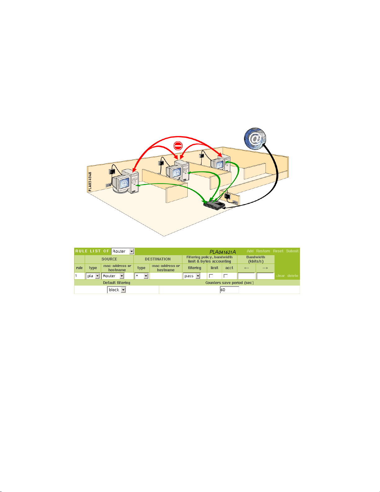
Internet access with privacy between the room
We want to provide Internet access in all of the hotel rooms, but prevent communications between the room to protect each user from possible intrusion (network neighbourhood, access to shared resources, etc.)
1. The PLA (Router) can reach all (*) of the devices present on the powerline network.
Due to the nature of a network, this rule is two-way, which means:
All (*) of the devices present on the powerline network have access to the PLA (Router),
and therefore to the router.
F Remember to set the default behaviour to "block".
Page 35
8 GRAPHIC CONFIGURATION 35
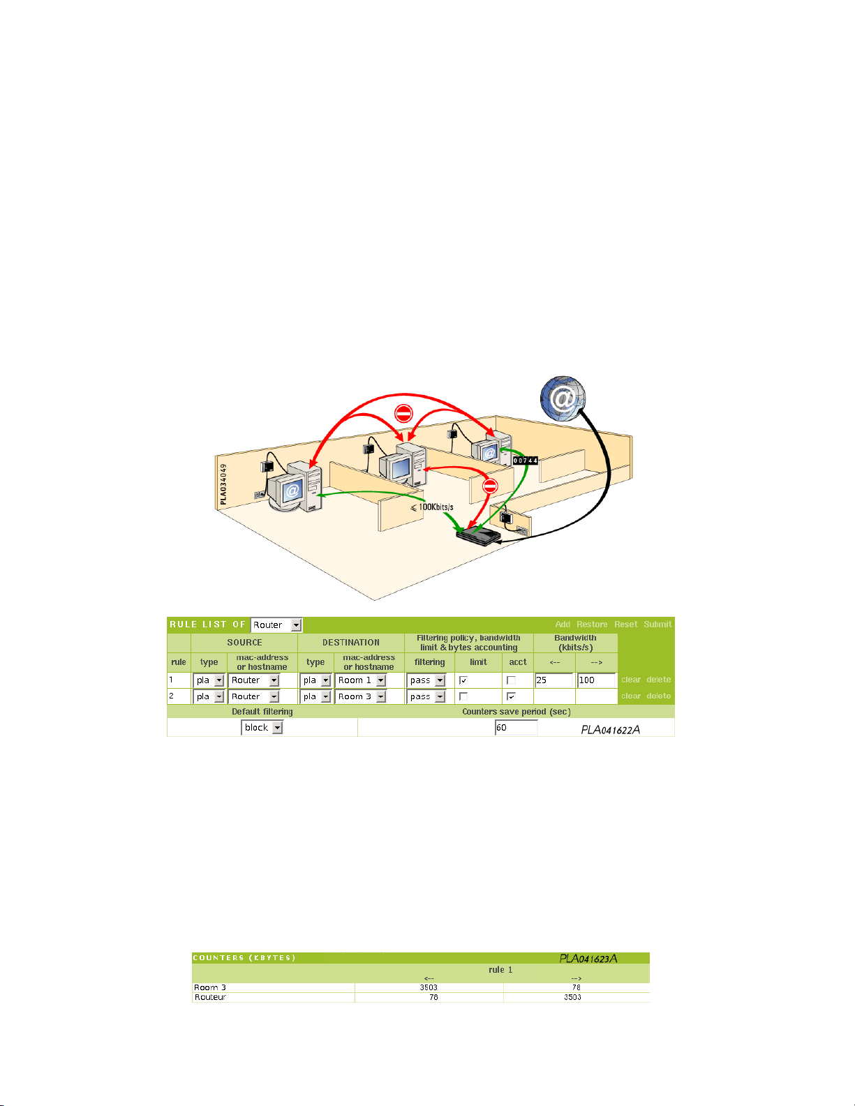
Personalized Internet Access
We want to provide personalized internet access as follows :
● Room 1 should access the Internet with a bandwidth limited to 100 kbits/s in-
coming and 25 kbits/s outgoing.
● Room 2 has no Internet access.
● Room 3 should access the Internet with no bandwidth limitation, but with billing
based on volume.
● The rooms must not be able to communication with one another.
1. The PLA (Router) can reach the PLA (Room 1) and vice versa. The data rate of Room
1 is limited to 100 kbits/s incoming (router to room) and 25 kbits/s outgoing (room
to router).
2. The PLA (Router) can reach the PLA (Room 3) and vice versa with no bandwidth
limitation. The counter is activated to track the number of kbytes transferred.
F Remember to set the default behaviour to "block".
Rule 2 tells the PLA to count the kbytes transferred between the router and room 3.
Once the rules are validated, click on "Global Network - Security" again to display the
counter table showing the kbytes received "<–" and sent "–>" by the PLAs.
F Caution: you have to wait at least the amount of time between autosaves (by
default 60 seconds) to view the changes.
Page 36
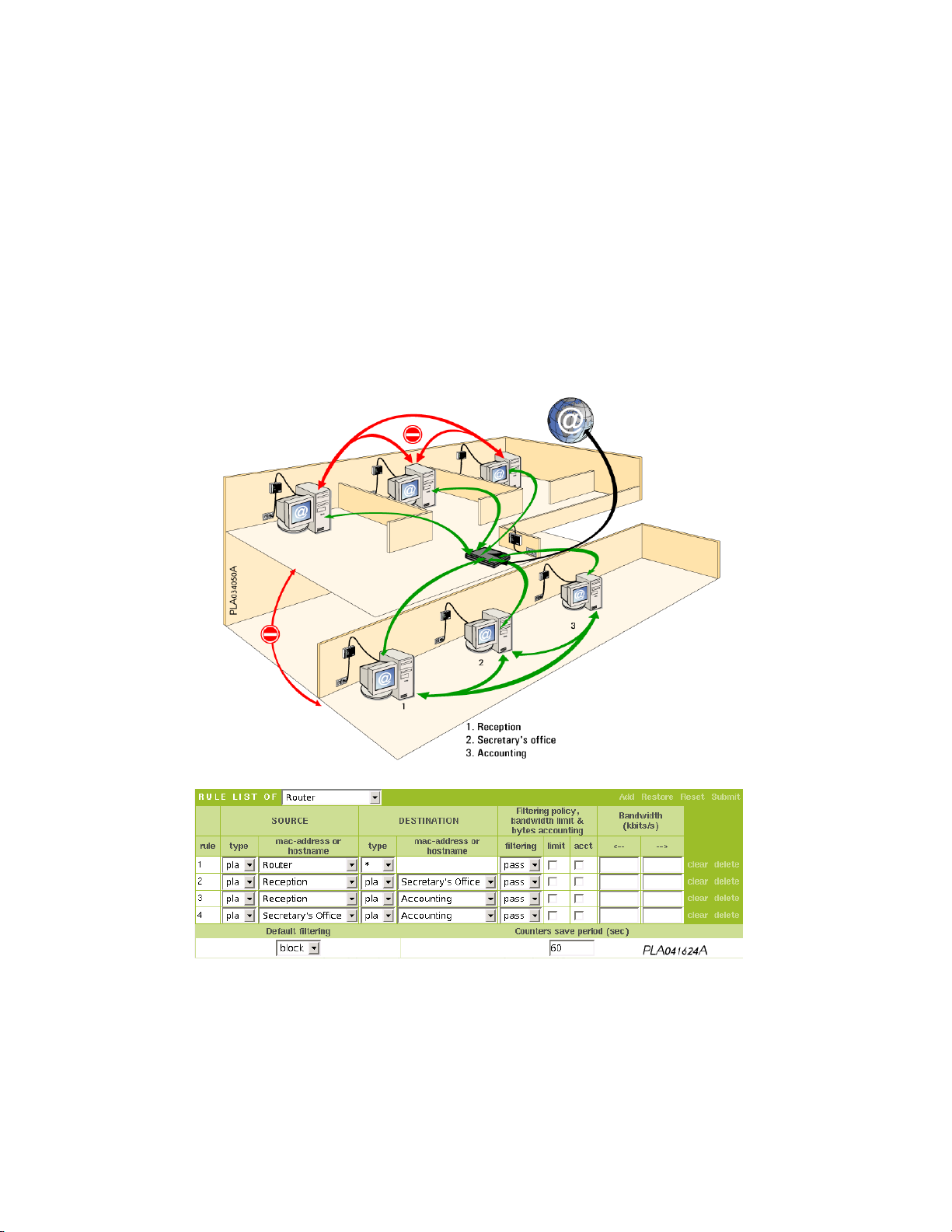
8 GRAPHIC CONFIGURATION 36
Separate Administration Network and User Network.
The administrative network (composed of three computers) must be separated from the
user network (the rooms) :
● All of the computers must be able to access the internet with no restrictions.
● The computers in the rooms must not be able to communication with one another.
● The computers in the administrative network (Reception, Secretary’s Office, Ac-
counting) must be able to communicate with one another.
1. The PLA (Router) can reach all (*) of the devices present on the powerline network
and vice versa.
2. The PLA (Reception) can reach the PLA (Secretary’s office) and vice versa.
3. The PLA (Reception) can reach the PLA (Accounting) and vice versa.
4. The PLA (Secretary’s Office) can reach the PLA (Accounting) and vice versa.
F Remember to set the default behaviour to "block".
Page 37
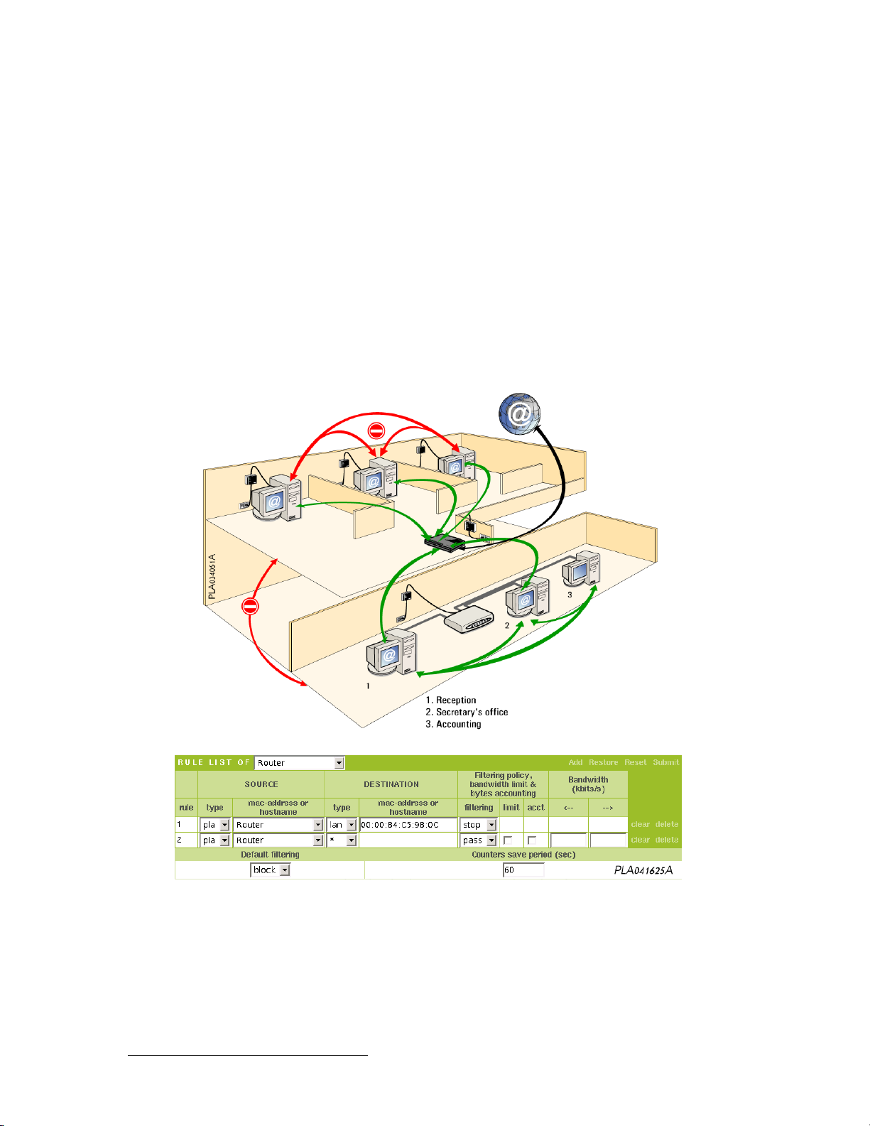
8 GRAPHIC CONFIGURATION 37
Separate Administration Network and User Network
Same configuration as in case 3, but the administrative network computers are all connected to a hub that is connected to a PLA :
● The administrative network (composed of three computers connected via a hub)
must be separate from the user network (the rooms).
● All of the computers must have Internet access except the Accounting computer
in the administrative network, whose MAC address is 00:00:b4:c5:9b:0c.
● The computers in the rooms must not be able to communication with one another.
1. The PLA (Router)cannot not access the Accounting computer whose MAC address
is 00:00:b4:c5:9b:0c and vice versa.
2. The PLA (Router) can reach all (*) of the other devices present on the powerline
network and vice versa. All of the computers in the administrative network can
communicate with one another via the hub.
F Remember to set the default behaviour to "block".
5
To find your computer’s MAC address, see data sheet 1 page 66.
5
Page 38
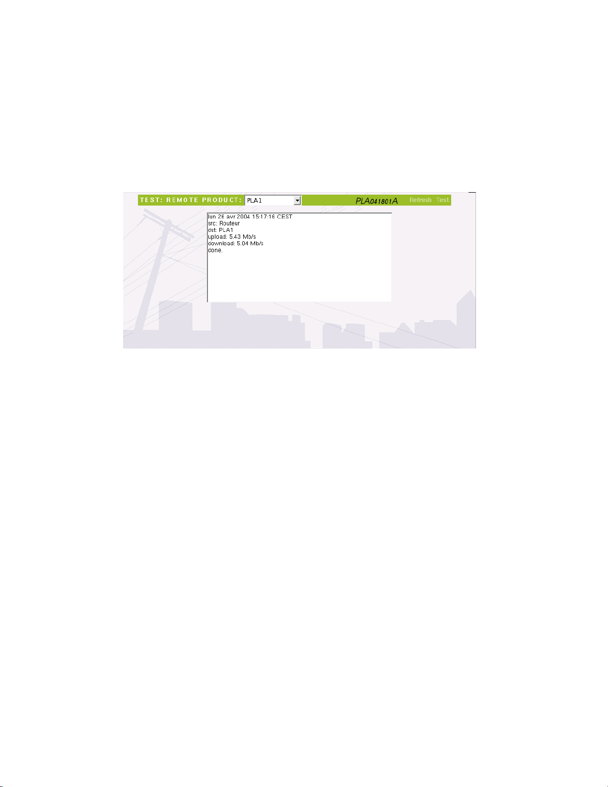
8 GRAPHIC CONFIGURATION 38
8.2.5 Global Network - Test
Test allows to calculate the bandwith (Mb/s) beetwen the Access point PLA and another
remote PLA.
A FTP transfer is done (upload and download) from Access point to the remote PLA.
Page 39
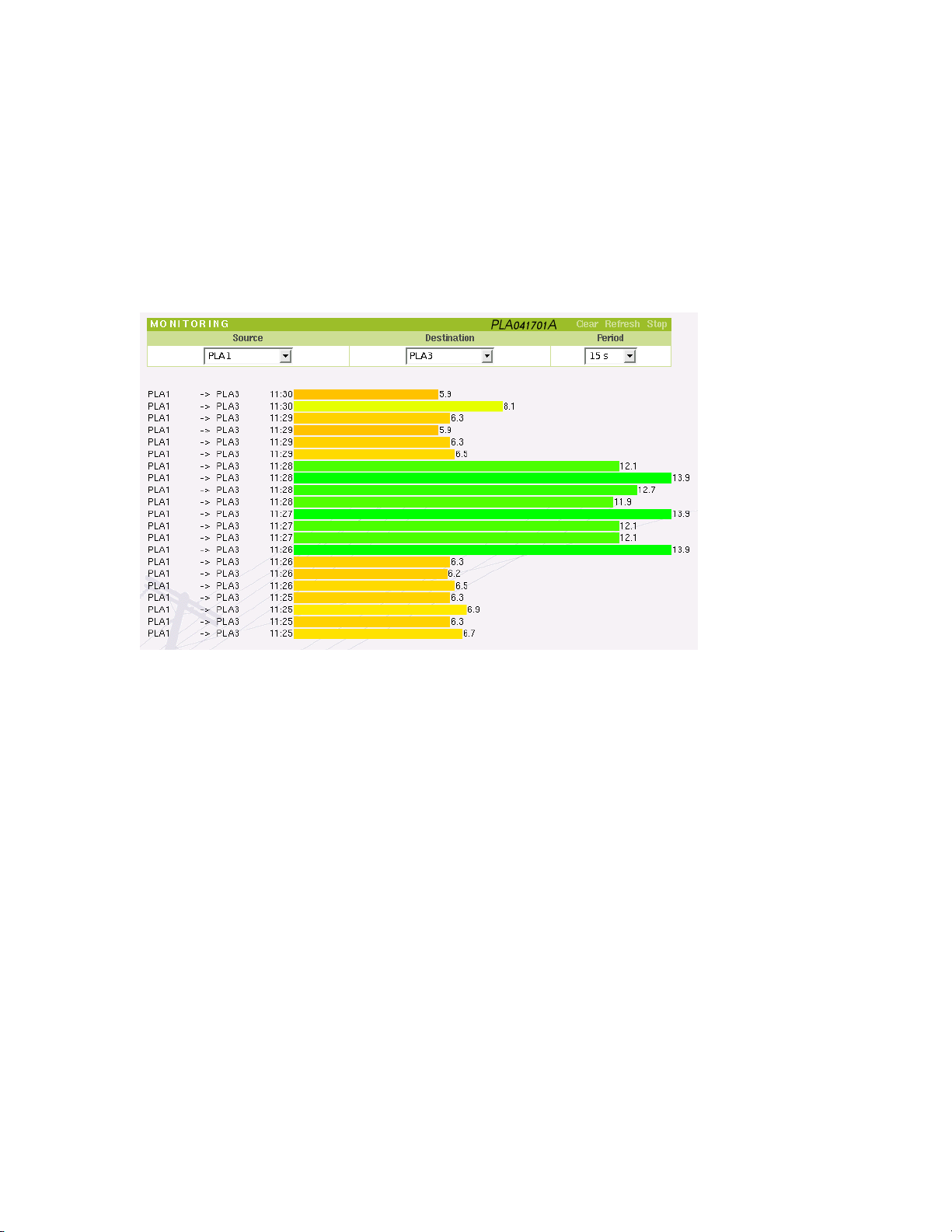
8 GRAPHIC CONFIGURATION 39
8.2.6 Global Network - Monitoring
Monitoring allows to graphically control the quality fluctuations beetwen 2 PLA along
the time.
You must setup the source, the destination PLA and the refresh period.
Example :
A PLA was intentionnaly connected into a surge protector.
When this surge protector is off, you can immediately see the bandwith improvement.
Page 40

8 GRAPHIC CONFIGURATION 40
8.2.7 Global Network - Save Config
The information entered via the web interface is stored in RAM memory on all of the
PLA200s.
To make sure the information is not lost even when there is a power outage, remember
to save it.
Page 41

8 GRAPHIC CONFIGURATION 41
8.3 PLA Selection
The scrolling menu displays the PLAs in alphabetical order. By default, The access
point PLA is selected.
Even while connected to the Ethernet network through this PLA200, you can access
local information from another PLA200 via the powerline network.
Under PLA Selection, you can view and change the settings only of the PLA selected.
Page 42
8 GRAPHIC CONFIGURATION 42
8.3.1 PLA Selection - Setup
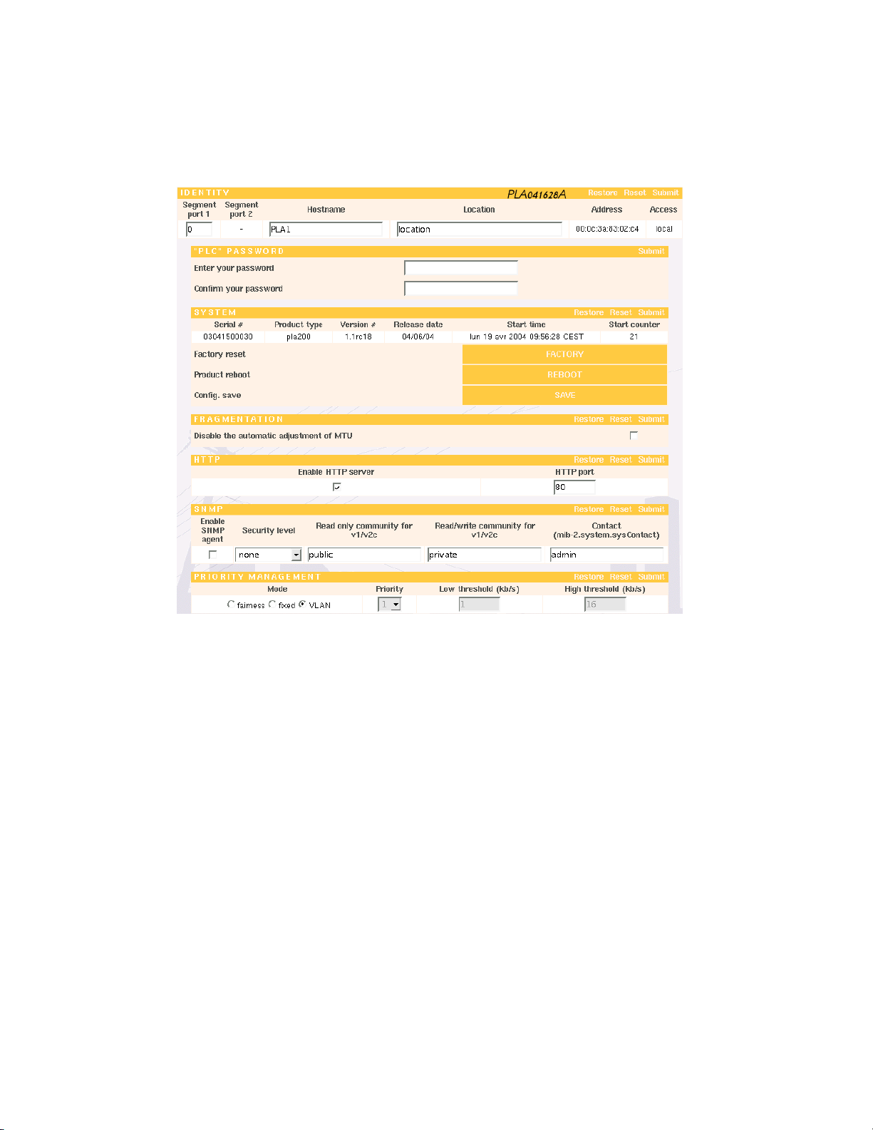
IDENTITY
• segment port 1 and segment port 2 : segments the PLA networks. Caution, this
setting should be used only if you have a PLA Bridge (see page 51).
• hostname : this field is composed of the last three bytes of the device’s MAC address
preceded by "pla_". It can be customized and may contain alphanumerical characters
(32 characters maximum).
• location : this field can be customized and may contain alphanumerical characters
(32 characters maximum).
• address : this is the MAC (Media Access Control) address of the PLA200, 6-byte hex
coded. The first three characters are reserved for the manufacturer (00:0c:3a for Oxance). The next three are digits from 0 to 9 or letters from A to F. This alphanumeric
string is unique and is used to identify the PLA200.
• access : this field indicates whether you are accessing the PLA200 directly (local) or
via the powerline network through the access point PLA200 (remote).
"PLC" PASSWORD
The data transmitted between the PLAs are always encrypted using the DES 56 bit
protocol. To work together, the PLAs on your network must all have the same encryption key. By default, all of the devices are shipped with the same encryption key
Page 43
8 GRAPHIC CONFIGURATION 43
"oxance.com".
You can move each individual PLA to another PLA network.
F Caution: If you assign a password here that is different from the other PLAs,
you will not be able to access this device after a save and restart. To access the
device you will have to either connect directly to the PLA (place your configuration computer on the same Ethernet network) or change the PLC password of the
local PLA so that it is on the same PLA network.
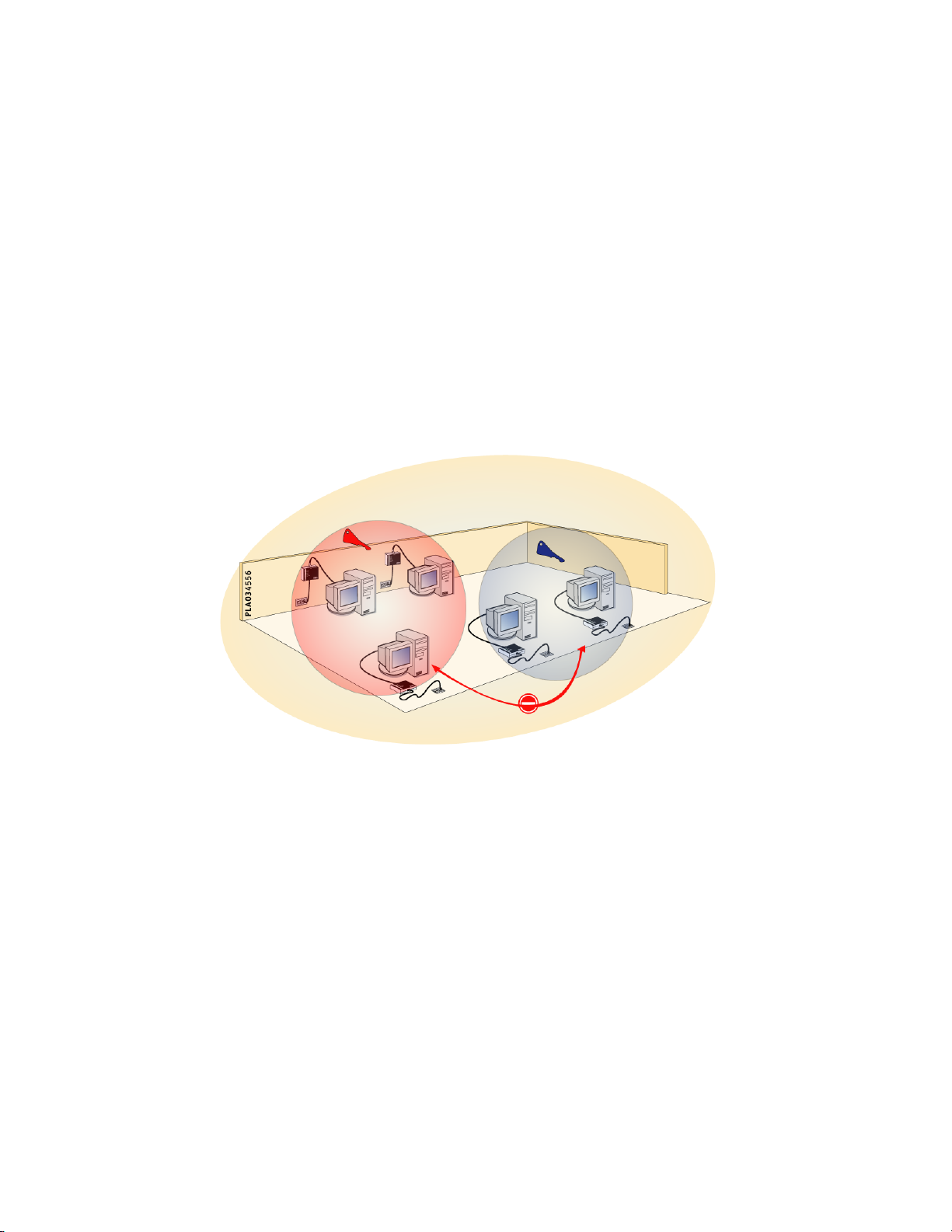
Due to the nature of the electric circuit, all of the PLA200s on a powerline network are
located on the same physical network. You can split this physical network into several
logical networks by assigning a different encryption key to each logical network.
It is useful to separate the users of physical network into two or more logical networks,
for example in a school (students / teachers) or a hotel (rooms / administrative).
How to create logical networks :
1. Identify all of the PLA200s belonging to the same logical network.
2. Select a PLA200.
3. Assign it a new PLC password.
4. Validate, and after 5 seconds, it will disappear from the list of PLA200s seen by
the access point (Global network - Products List - Refresh).
5. Repeat the operation for all of the PLA200s in the logical network.
Note: If necessary, finish by changing the PLC password of the PLA200 that serves as
access point. Now your logical networks are independent and unable to communicate
with one another.
Page 44

8 GRAPHIC CONFIGURATION 44
SYSTEM
Information about the product selected (serial number, type of product, version number, version date, start-up date, start-up number).
In this section you can also make a factory reset, restart the device, and save the settings.
FRAGMENTATION
• Disable the automatic adjustment of MTU : if a PLA receives TCP packets with
MTU greater than 1460 bytes via the Ethernet network, it adjusts the MSS (Maximum
Segment Size) to avoid fragmentation. This setting is enabled by default, and can be
disabled from this windows for the selected PLA.
HTTP
• Enable HTTP Server : You can disable the HTTP server of the PLA selected. If the PLA
selected is the local PLA, you will no longer be able to administer the device by HTTP.
However, it may be useful to disable the HTTP server of each remote PLA in order to
restrict access to the PLA network settings.
• HTTP port : Here you can change the TCP access port to the HTTP server.
SNMP
The PLA network can be administered using the SNMP protocol.
• Enable SNMP agent : To use this function, you must enable the SNMP of the PLA that
is on the same Ethernet network as the computer acting as SNMP host. Only one agent
is needed to administer a PLA network. It may be useful to enable a second agent if you
wish to create a back-up for a second SNMP manager located on a different Ethernet
network.
If you leave the security level set to "none" you can connect in SNMP V1 and V2c. In
this case, you can modify the "public" (read only) and "private (read-write) communities.
In SNMP V3, the authentication key and the encryption key match the PLC password
(by default: "oxance.com").
The MIB-2 is not included with the SNMP agent except for the system branch. The other
branches are of little interest, since a PLA network is more like an Ethernet hub than a
standard TCP/IP device.
The device is managed entirely using Oxance’s proprietary MIB available on our CDROM.
Page 45

8 GRAPHIC CONFIGURATION 45
Security Level:
● none (by default): compatible with SNMP V1, V2c and V3 without authentication
or encryption.
● auth : SNMP V3 only, with authentication.
● authPriv : SNMP V3 only, with authentication and possibility of DES encryption.
● authPrivAes : SNMP V3 only, with authentication and possibility of AES 128-bit
encryption.
PRIORITY MANAGEMENT
In order to optimise the network, you can change the priority management.
Priorities can be setup in 3 modes :
1 - VLAN : supports VLAN tag 802.1q (by default).
If an Ethernet frame contains a VLAN tag, then the tag priority determine the priority
of the frame when sent on the powerline.
2 - Fixed : fix the priority for frame transmission on the powerline.
1 low priority
2-3 medium priority
4-5 high priority
3 - Fairness : setup a priority management in relation with throughput.
To improve low data transfer (web, email...) compared to high data transfer (ftp, peer to
peer...), you can setup 2 threshold to determine 3 priority classes.
A low and high threshlod allows to setup the priority level (by default low=1kb/s and
high=16kb/s).
0<data rate<threshold low high priority
threshold low<data rate < threshold high medium priority
data rate > threshold high low priority
Page 46
8 GRAPHIC CONFIGURATION 46
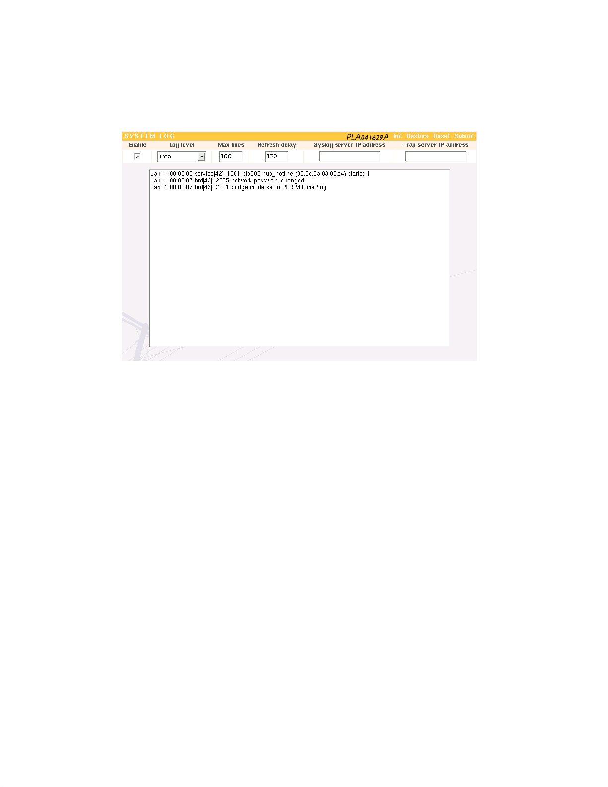
8.3.2 PLA Selection - System Log
SYSTEM LOG
● Enable : enable or disable the audit daemon, which creates a system infor mation
log.
● Log level : select message type (Warning, Notice, Info).
Three methods are used to pass along the information :
• HTTP (logs displayed on the web page)
Max. lines : indicate the number of lines to display on your screen. Old messages are
deleted and replaced by new ones as they arrive.
Refresh delay : this is the time in seconds between two web page auto-refreshes.
• SYSLOG (retrieval of logs fr om a remote computer)
You have to have a syslog daemon on a remote computer. For Windows systems that do
not have a syslog daemon, you can download one at “http://www.kiwi-enterprises.com”.
Sylog Server IP address : IP address of the remote computer.
• TRAP (log retrieval using an SNMP management utility)
If you have SNMP management software on your network, you can view the logs in trap
mode. Trap retrieval utilities are available at the following website: “http://www.ncomtech.com/download.htm”.
TRAP Server IP address : IP address of the SNMP management software.
Page 47

8 GRAPHIC CONFIGURATION 47
SYSLOG LIST
WARNING
● 1001 PLA_type name (mac-address) started ! : when product starts
NOTICE
● 1002 system is up down : product is rebooting
● 1003 configuration saved : the current configuration has been saved in flash memory
● 1004 IP-set ping, changing to ip_address : product got a new ip address
● 2001 bridge mode set to (PLRP/HomePlug | PLRP/PLRP) : bridge changed its mode
● 2002 AES encryption is (ON | OFF) : AES encryption has been enabled or disabled
● 2003 change port1 segment from old_segment to new_segment : bridge has change its port1
segment
● 2004 change port2 segment from old_segment to new_segment : bridge has change its port2
segment
● 2005 network password changed : powerline network password has been changed
● 2006 PLA mac-address is out (no response from ping) : the PLA mac-address has disap-
peared from the powerline network
● 3001 monitoring: quality to join mac-address is under low level : quality for mac-address
went through the lower trigger level
● 3002 monitoring: quality to join mac-address is over high level : quality for mac-address
went through the higher trigger level
● 4001 update: erasing flash (start, length) : update process is erasing this flash part
● 4002 update: duplicated flash_source to flash_dest : update process duplicated a flash part
from current partition to next partition
● 4003 update: filename downloaded successfully in device_name : update process has suc-
cessfully downloaded and stored a file
● 4004 update: same version number (version). Skipping update.... : update has been
aborted because release version is the same as current version
● 4005 update: successfully done : update has been successfully completed
INFO
● 2007 missing PLA: ping #number s:mac_source -> d:mac_destination : a ping has been
sent to mac_destination to test if PLA is still present
● 3003 monitoring: mac-address is now accessible : monitored PLA mac-address previously
not accessible, is now accessible
● 3004 monitoring: mac-address cannot not be accessible : monitored PLA mac-address
previously accessible, is now not accessible
● 4006 update: ask to mac-address to update : update server ask to mac-address to start its
update client process
Page 48
8 GRAPHIC CONFIGURATION 48
8.3.3 PLA Selection - Route
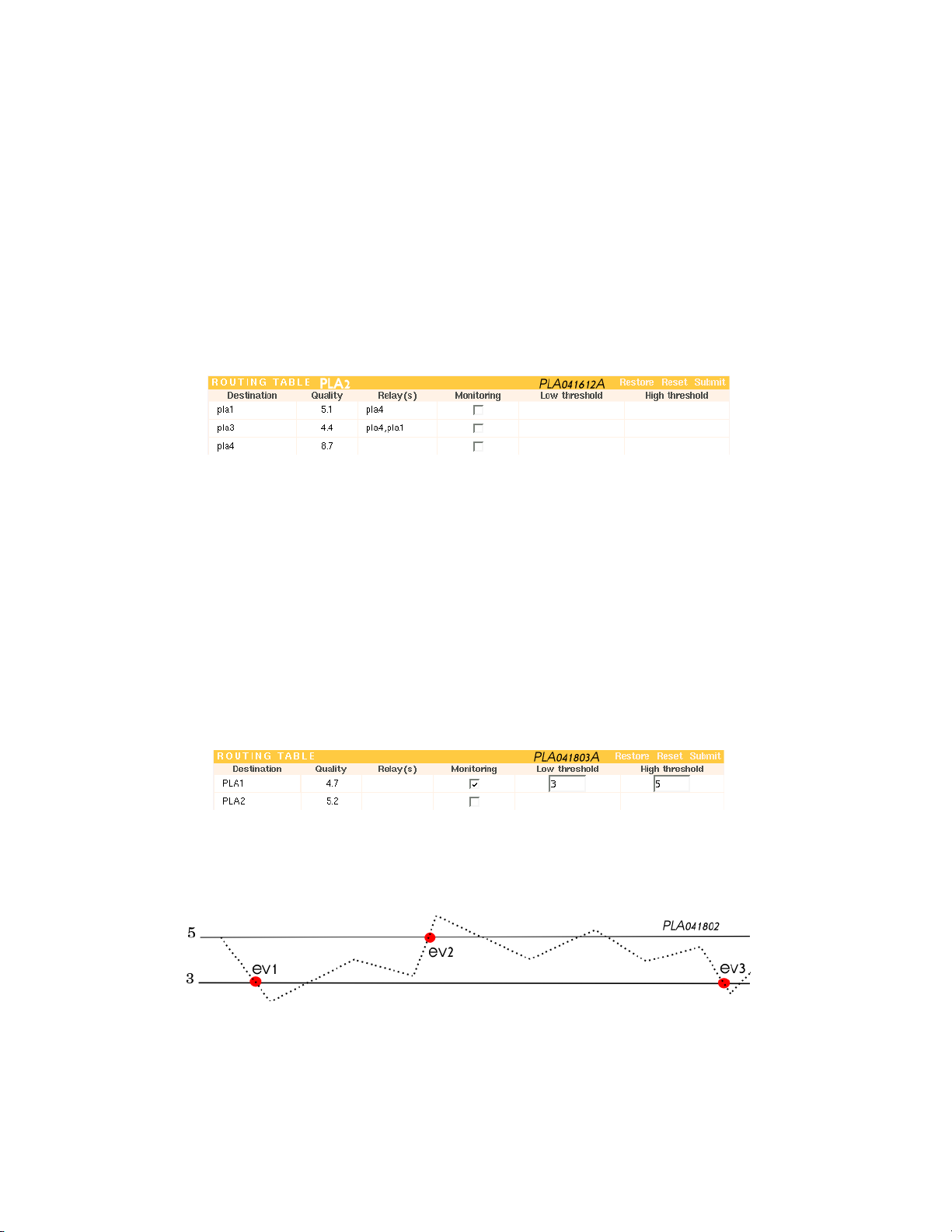
This table indicates the route taken by an Ethernet frame, at a given moment, to get to
the PLA behind which the destination Ethernet device is located. It is not necessarily a
direct route. The frame may use one or more relays before reaching its final destination.
The best route for each destination is always being recalculated, which is why this table
is constantly changing..
ROUTING TABLE
Destination : Final PLA behind which the destination Ethernet device is located.
Quality : estimate of the communication quality.
Relay(s) : The Ethernet frame will be relayed before reaching the final PLA.
Monitoring : allows to control the communication quality beetwen the selected PLA
and another.
Low threshold : when the quality goes under this threshold, an event is sent to the
system log.
High threshold : when the quality goes over this threshlod, an event is sent to the
system log.
Example :
A monitoring beetwen a PLA router (the selected PLA) and the PLA1. The low threshlod
is setup to 3M and high is setup to 5M, system log must be enabled.
This chart shows the monitoring process :
3 events are sent to the system log :
ev1 and ev3 -> 3001 monitoring : quality to join mac-address is under low level
ev2 -> 3002 monitoring : quality to join mac-address is over high level
Page 49
8 GRAPHIC CONFIGURATION 49
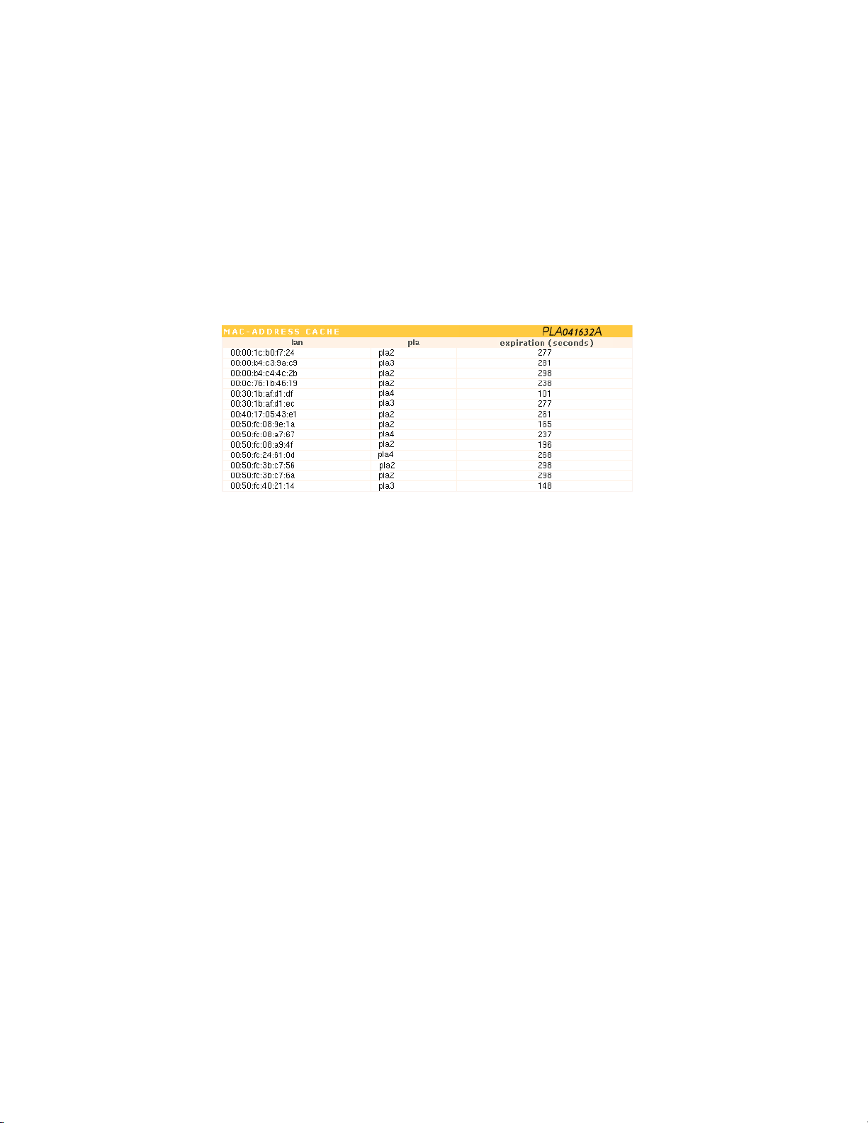
8.3.4 PLA Selection - LAN/PLA
Provides a list of the Ethernet devices behind each PLA. The Ethernet device is represented by its MAC address. A device is added to the list as soon as communications are
established with it. It disappears from the list after a certain period with no communications.
MAC ADDRESS CACHE
Page 50

8 GRAPHIC CONFIGURATION 50
8.3.5 PLA Selection - Save Config
The information entered via the web interface is stored in the RAM memory of the
PLA200. To make sure the information is not lost even after a restart, remember to
save it.
Page 51
9 PLA 220 (BRIDGE) 51
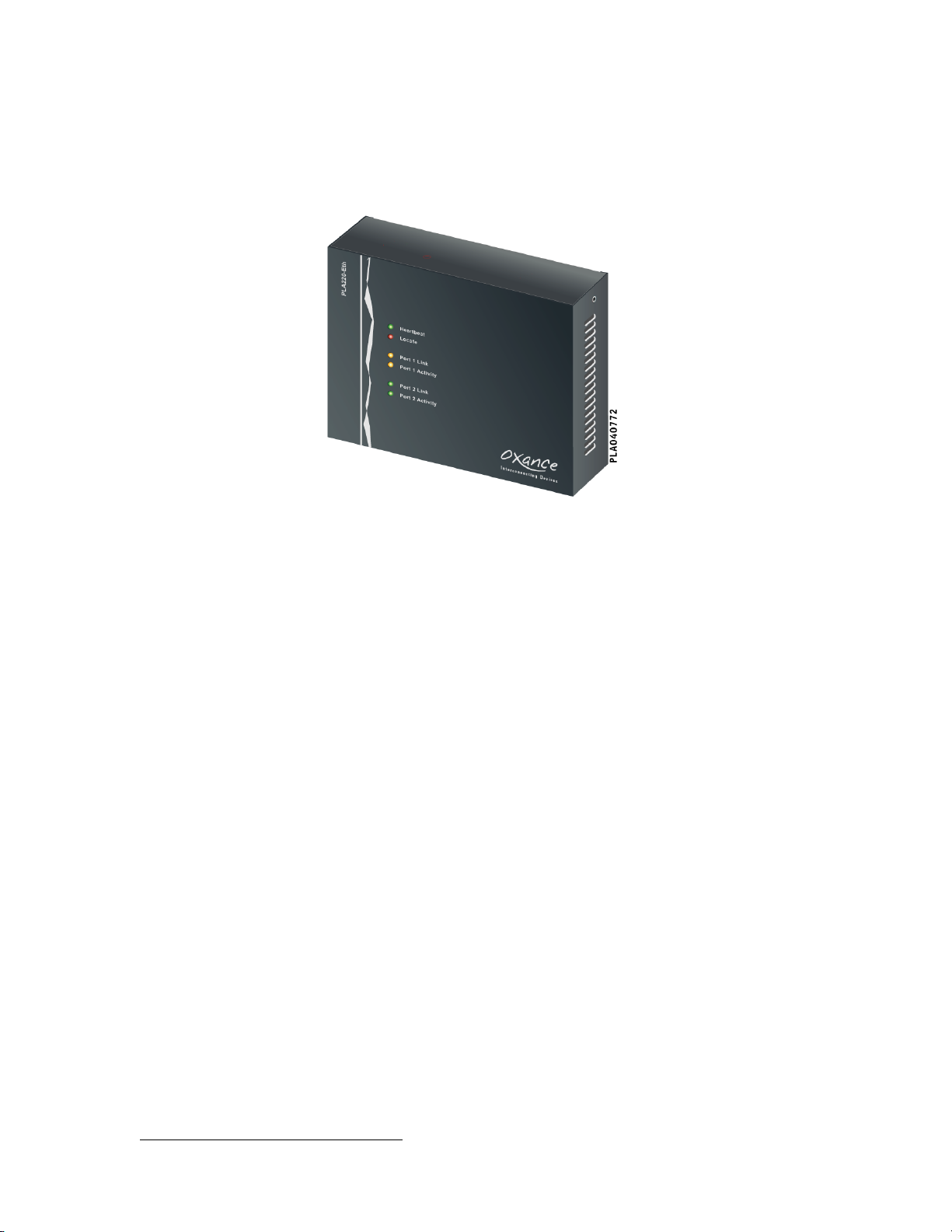
9 PLA 220 (Bridge)
The PLA220 does not have an Ethernet interface. It has two Powerline IEC320 interfaces, whereby it can :
• ensure compatibility between a HomePlug network (PL100-ETH, PL100-USB, PL110ETH) and a PLRP6network (PLA200)
• segment all of the HomePlug or PLRP adaptors on the same powerline network into
groups of 15 devices.
With the PLA220 Bridge, you can choose between two software configurations (PLRPHomePlug or PLRP-PLRP). In both cases, the PLA220 keeps a PLRP interface that allows
it to use the advanced functions of the PLA200s (repeater, dynamic routing).
6
PLRP (PowerLine Routing Protocol) is the name of the routing algorithm developed by Oxance and inte-
grated in the PLA2xx.
Page 52
9 PLA 220 (BRIDGE) 52
9.1 PLA200 Compatibility with HomePlug 1.0.1 devices
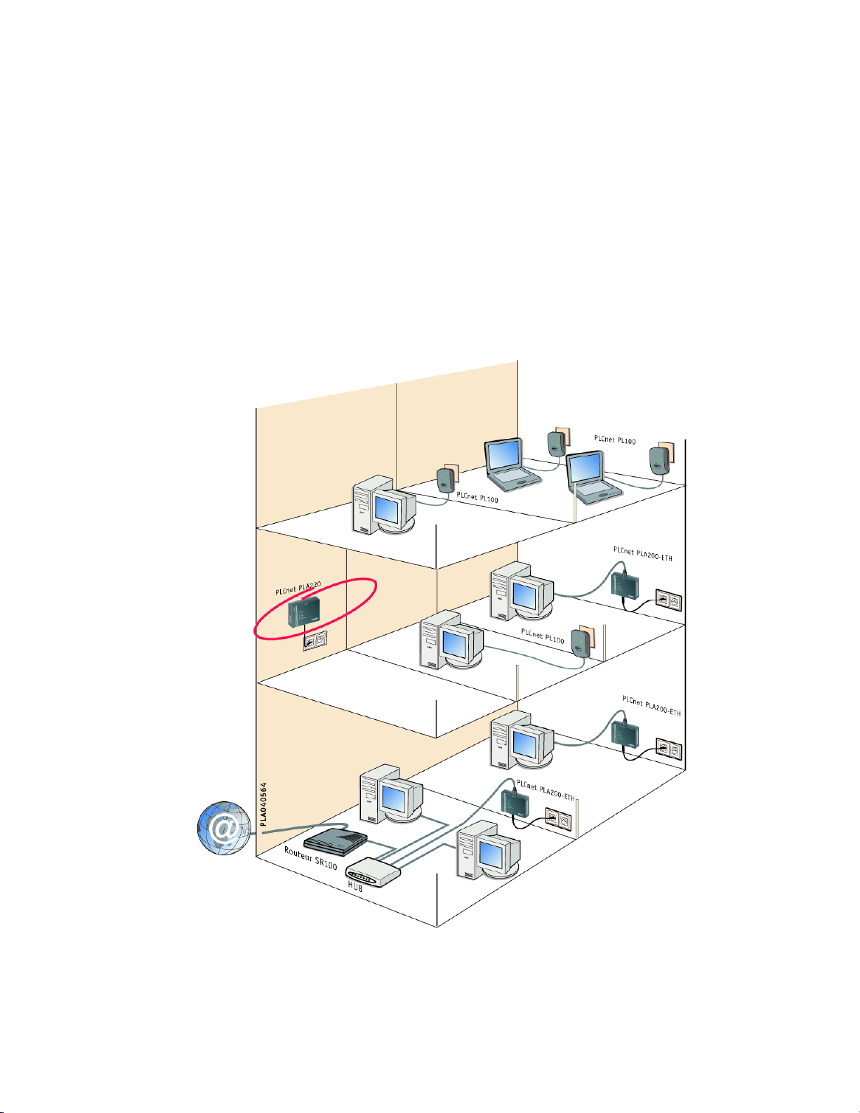
Although the PLA200s are based on HomePlug 1.0.1 technology, they use the PLRP algorithm developed by Oxance, which resolves certain problems inherent in the HomePlug
protocol, such as limits on distance and the number of devices that can be connected.
However, the PLA200s cannot communicate directly with HomePlug certified devices
(PL100-ETH, PL100-USB, PL110-ETH) over the same Powerline Communications network.
To connect the networks, you must use a PLA220 in PLRP-HomePlug mode so that the
devices can communicate via its two interfaces.
Page 53
9 PLA 220 (BRIDGE) 53
Setup the PLA220 bridge (PLRP-HomePlug)
The PLA220 has no Ethernet interface. You have to connect to a PLA200 via Ethernet,
and then from the menu "PLA Selection" you can reach the PLA220 over the powerline.
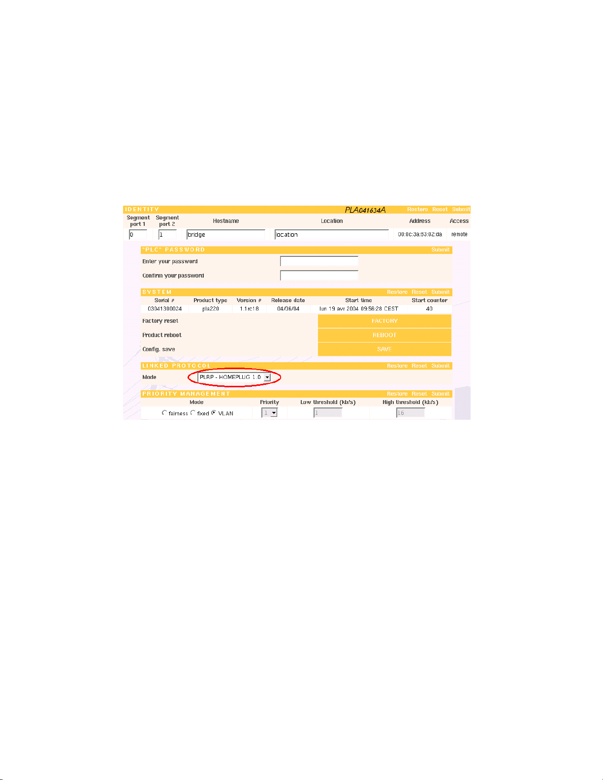
PLA Selection - Setup
LINKED PROTOCOL
Make sure that the mode is set to PLRP - HomePlug 1.0 (default setting)
In this mode, the PLA220 has one PLRP interface and one HomePlug interface. Otherwise, change, save, and restart so that the changes are implemented. After restarting,
the "PLA Selection - HomePlug" section of the PLA220 should be accessible.
The default password for all HomePlug devices (PL100-ETH, PL100-USB, PL110-ETH)as
well as the HomePlug interface of the PLA220 is "HomePlug".
F If all of your devices are set to the factory settings, simply plug the bridge into
the powerline network and all of the PLRP and HomePlug adapters will be able to
communicate with one another.
Page 54
9 PLA 220 (BRIDGE) 54
PLA Selection - HomePlug
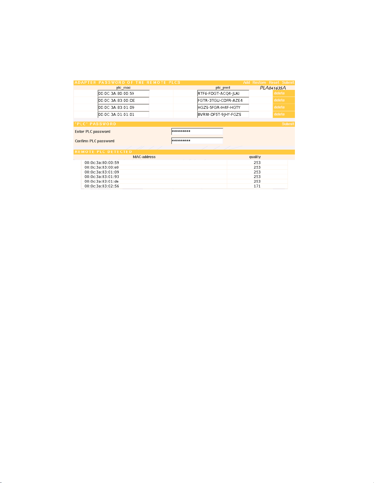
From this page you can change the encryption key for the HomePlug adapters present
on the network. It works the same way as the "Advanced" tab of the configuration utility
shipped with the HomePlug devices (PL100-ETH, PL100-USB, PL110-ETH).
REMOTE HOMEPLUG ADAPTER PASSWORD
• mac address : Indicate the MAC address of your PL100 or PL110 adapter here.
The address format is xx:xx:xx:xx:xx:xx and is printed on the device label (for example
"00:0c:3a:80:00:59").
• password : Indicate the password of your PL100 or PL110 adapter here. The password
format is xxxx-xxxx-xxxx-xxxx and is printed on the device label (for example "RTY6FVBG-3GRT-ASQD").
Once your list is complete, remember to validate and save from the menu "PLA Selec-
tion - Save Config".
“HOMEPLUG” PASSWORD
Indicate the DES 56-bit encryption key that will be sent to all of the devices defined on
your list and to the PLA220’s HomePlug interface.
F Caution : If you make a mistake in entering the MAC address or password, the
key will not be sent to the device.
REMOTE HOMEPLUG DEVICES DETECTED
This provides a list of HomePlug adapters detected by the Bridge.
The MAC address of each PL100 and PL110 detected is displayed, as well as an estimate
of the communication quality with the PLA220 Bridge.
Page 55

9 PLA 220 (BRIDGE) 55
9.2 Segment a Powerline Network
Due to the HomePlug protocol design, each PLA or HomePlug device manages an internal table of 15 MAC address. To simplify, a PLC adapter can send a packet directly to
any one of the 15 devices defined in its table, at any time.
F With 15 devices on a network, everyone knows each other and communications
are optimal.
With 16 devices or more, each adaptor does necessarily not have the same 15 MAC
address table as its neighbour. If the destination address is not in the table of the
transmitting product, it sends its request to the entire network (Broadcast) and the
data transfer switches to degraded mode (ROBO mode, 1 Mbps raw bit rate). The more
devices are connected, the greater the risk of switching to ROBO mode.
Example :
To transfer a file between two computers on a powerline network :
15 computers -> best case -> TCP rate approximately 6Mbps between the 2 computers
25 computers -> ROBO mode 1 Mbps rate bit rate -> TCP rate approximately 0.42Mbps
F Whenever you have 16 devices or more, we highly recommend using bridges
to segment your network into groups of 15 devices maximum. This will prevent
network overload
Whenever a PLA220 bridge (PLRP-PLRP) is necessary on a powerline network, you must
assign a segment number to the PLAs. When you assign a segment to a PLA, you create
separate groups of PLAs.
To keep things clear and simple, we recommend not using the number 0 (default setting on all the PLAs) when you segment the network. A PLA with segment set to 0 is
considered to belong to a non-segmented PLA network.
Page 56
9 PLA 220 (BRIDGE) 56
Setup the PLA220 bridge (PLRP-PLRP)
The PLA220 has no Ethernet interface. You have to connect to a PLA200 via Ethernet,
and then from the menu "PLA Selection" you can reach the PLA220 over the powerline.
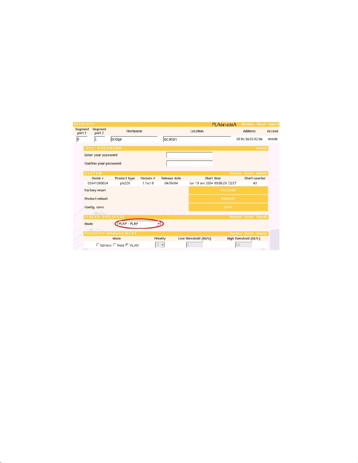
PLA Selection - Setup
LINKED PROTOCOL
Set the PLA220 to mode PLRP - PLRP
Save and restart the device so that the changes are implemented. After restarting, the
bridge has two PLRP interfaces.
Once there are more than 15 PLRP devices (PLA200) on a powerline network, it must
be segmented.
Segmentation is done from the menu "Global Network - Products List - Segment Edi-
tion"
In order facilitate segmentation :
1. Give specific names to all of the PLA200s.
2. Split the PLA200s into groups of 15 maximum based on their physical location
(same fllor, same room, etc.)
Page 57
9 PLA 220 (BRIDGE) 57
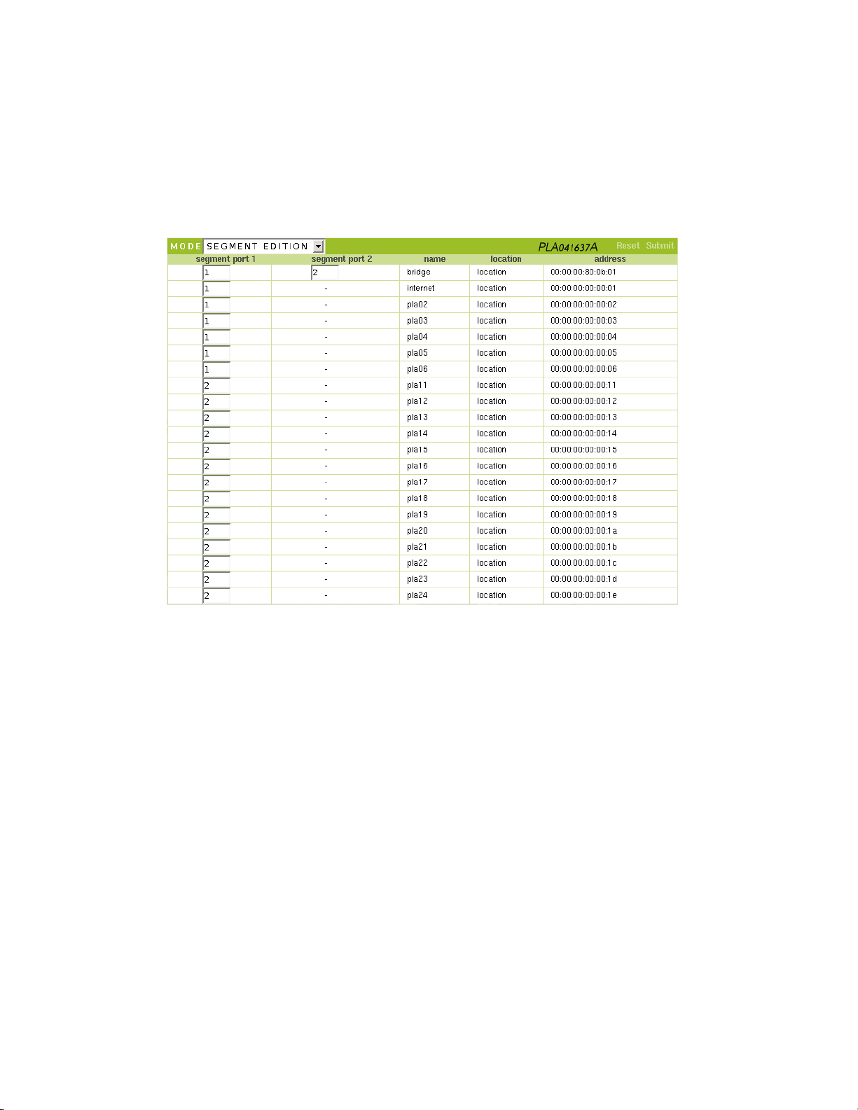
Global Network - Products List
The Segment edition mode allows you to assign the segment numbers to all of your
PLAs on one page.
Once your network is segmented, the list of devices is sorted by segment and then alphabetically by device names within the segment. The configuration is complete, and
your network is optimised and operational.
Remember to save from the menu "Global Network - Save Config".
Before segmenting your network, refer to the examples on the following page.
Page 58
9 PLA 220 (BRIDGE) 58
9.3 Examples of how PLA bridges are used
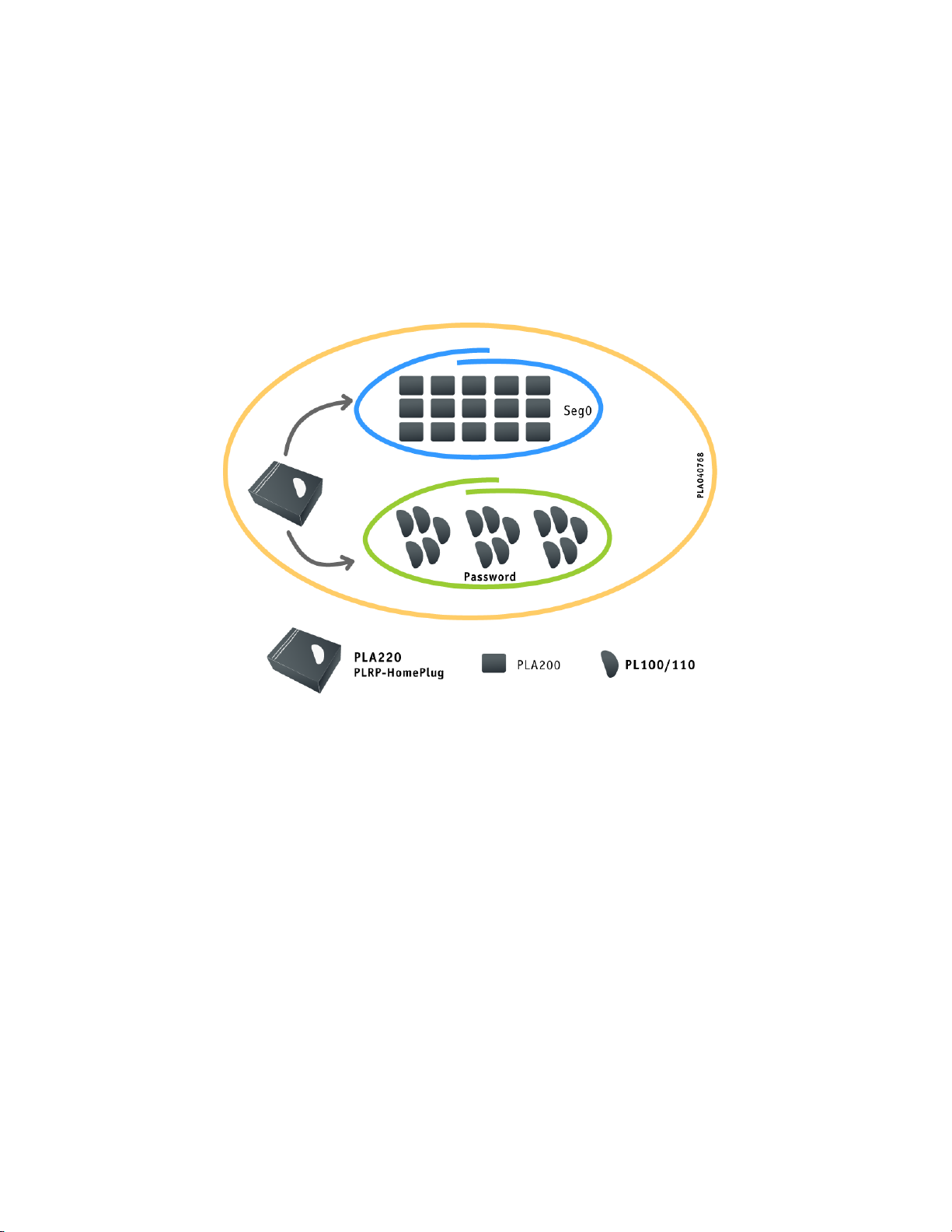
9.3.1 A Powerline Network with 15 PLA200s and 15 PL100s
To enable the devices to communicate, use 1 PLA220 bridge set to PLRP-HomePlug mode.
Method :
● The PLA200 network is not segmented, so you must leave the segment set to 0 on the
PLA200s.
● Set the PLA220 bridge to PLRP-HomePlug mode and enter the list of 15 PL100s with their
adaptor passwords from the page "PLA Selection - HomePlug"
Page 59
9 PLA 220 (BRIDGE) 59
9.3.2 A Powerline Network composed of 21 PLA200s
To avoid degraded mode (ROBO mode), use 1 PLA220 bridge set to PLRP-PLRP mode.
Method :
● Since the PLRP network is segmented, you must number the segments starting with 1.
● Split the PLAs into two groups (15 and 6). If possible build your segments based on the
physical location of your devices (same floor, same room, etc.).
● Assign the first 15 PLA200s to segment 1 and the other 6 PLA200s to segment 2.
● Assign the PLA220 bridge to segments 1 and 2.
Page 60
9 PLA 220 (BRIDGE) 60
9.3.3 A Powerline Network composed of 75 PL100s
All of the PL100s must be able to reach a router (Internet). In order to optimise communications and prevent switching to degraded mode (ROBO mode) use 5 PLA220 bridges set to PLRP-
HomePlug mode to create groups of PL100s and act as repeaters if necessary to communicate
with the router.
Method :
● The PLRP network is not segmented, so you must leave the segment set to 0 on the PLA220s.
● Split the PL100s into five groups of 15. If possible build your segments based on the
physical location of your devices (same floor, same room, etc.).
● Set each PLA220 bridge to PLRP-HomePlug mode and enter the list of 15 PL100s with their
adaptor passwords from the page "PLA Selection - HomePlug".
● A different HomePlug password must be assigned to each of the 5 groups.
Page 61
9 PLA 220 (BRIDGE) 61
9.3.4 A Powerline Network composed of 75 PLA200s
As in the second case, avoid degraded mode (ROBO mode), by using 5 PLA220 bridges set to
PLRP-PLRP mode.
Method :
● Since the PLRP network is segmented, you must number the segments starting with 1.
● Split the PLAs into five groups of 15. If possible build your segments based on the physical
location of your devices (same floor, same room, etc.).
● Assign the same segment to all of the PLA200s in one group (in this case 5 different seg-
ments: 2, 3, 4, 5, 6).
● Assign segment 1 to all of the PLA220 bridges on one interface and the PLA segments (2, 3,
4, 5, 6) to the other inter face
Page 62
9 PLA 220 (BRIDGE) 62
9.3.5 A Powerline Network composed of 21 PLA200s and 30 PL100s
Here we combine the architectures of the preceding cases using 4 PLA220 bridges (2 are set to
PLRP-HomePlug mode and 2 are set to PLRP-PLRP mode).
Method :
● Since the PLRP network is segmented, you must number the segments starting with 1.
● Split the PLAs into four groups (2 groups of PLA200s and 2 gro ups of PL100s). If possible
build your segments based on the physical location of your devices (same floor, same room,
etc.).
● Set 2 PLA220 bridges to PLRP-HomePlug mode and enter the list of 15 PL100s from the page
"PLA Selection - HomePlug". A different HomePlug passwor d must be assigned to each of
the 2 groups.
● Assign the same segment number to all of the PLA200s in one group (in this case 2 different
segments: 2, 3)
● Assign segment 1 to the two PLRP-PLRP PLA220 bridges on one interface and the PLA200
segments (2, 3) to the other inter face.
Page 63

10 SPECIFICATIONS 63
10 Specifications
Products PLA200 PLA220
Ethernet
PLC Interface IEC320 IEC320+IEC320
Certification
Speed
RJ45 No interface
HomePlug V1.0.1 - IEEE 802.3 - CE
14Mbps
Maximum PLA
number
Lights
250 PLC interfaces : 1 PLA200 = 1 interface and 1 PLA220 = 2 interfaces
Heartbeat
Locate
PLA Link
PLA Activity
Ethernet Link
Ethernet Activity
Dimensions 127x100x36 mm 127x100x36 mm
Weight 470 g 470 g
Operating
Temperature
Storage
Temperature
Operating
Relative humidity
Storage Relative
humidity
Power supply
Sécurité et EMI
Fonctionnal
isolation
Warranty
EN55022 - EN55024 - EN60950 EN61000-3.2 & 3.3
0oà 70oC
-55oà +125oC
10% à 90% no-condensing
0% à 95% no-condensing
220V - 50Hz - 35mA
1,5 kV
2 years
Heartbeat
Locate
Port1 Link
Port1 Activity
Port2 Link
Port2 Activity
Page 64

11 TROUBLESHOOTING 64
11 Troubleshooting
If the powerline network doesn’t work :
1. Make sure that the PLA Link light is on. It indicates that the device has detected
another PLA2xx on the network.
2. Make sure that all of your PLA2xxs are correctly plugged in to the electrical outlets.
Make sure that your electrical outlet is working by plugging in another electrical
device.
If it is working, try another outlet.
Do not plug an uninterruptible power supply or your computer into the same
outlet block.
Do not plug a PLA2xx into an outlet that is protected or equipped with a filter
(lightning or surge protector).
3. Check the Ethernet cables.
The Ethernet Link light goes on if another Ethernet device is detected at the other
end of the cable.
If the light does not go on, make sure that both devices are turned on and that the
cable is not defective.
4. Make sure that the PLA2xxs are all present on the powerline network.
Connect to a PLA using your browser : Menu "Global Network - Products List". If
all of the adapters are present, go on to step 5.
If any of the adapters is not listed :
The PLA2xxs may have been programmed with a different encryption key (check
the PLC passwords of your adaptors).
Unplug the undetected adaptors, then plug them back in and try this step again.
5. Make sure that the connection between your network devices is working.
Use the "ping" utility that tests the response time between two devices.
[ping the IP address of a network device]. It should send back 4 good data packets.
If it still doesn’t work, the PLA200 may be defective. Contact your dealer to get a return
merchandise authorization (RMA) to obtain a replacement.
If the powerline network is working very slowly :
A slow connection is almost always due to a poor electrical connection.
1. For three-phase power systems, use our phase coupler (ref : CPL3PH).
2. Plug your PLA200s directly into a power outlet and not a power strip or extension
cord. If necessary use a single-to-double T -shaped adaptor, see page 15.
3. Try a different wall outlet.
4. Do not use an outlet that is protected or equipped with a filter (lightning or surge
protector).
5. Try to identify the electrical interference (Global Network - Quality), see page 24.
6. Make sure that the PLAs are all on the same power system.
Page 65

12 MOUNTING KIT 65
12 Mounting Kit
Wall Mount
Optional 35 mm DIN Rail kit (ref : KIT35-A)
Page 66
13 DATA SHEETS 66
13 Data Sheets
Data Sheet 1
13.1 How do I find the MAC address of a network device ?
The MAC address is the unique identifier of a network interface card.
To set filtering rules on a specific device, you need to know the MAC address.
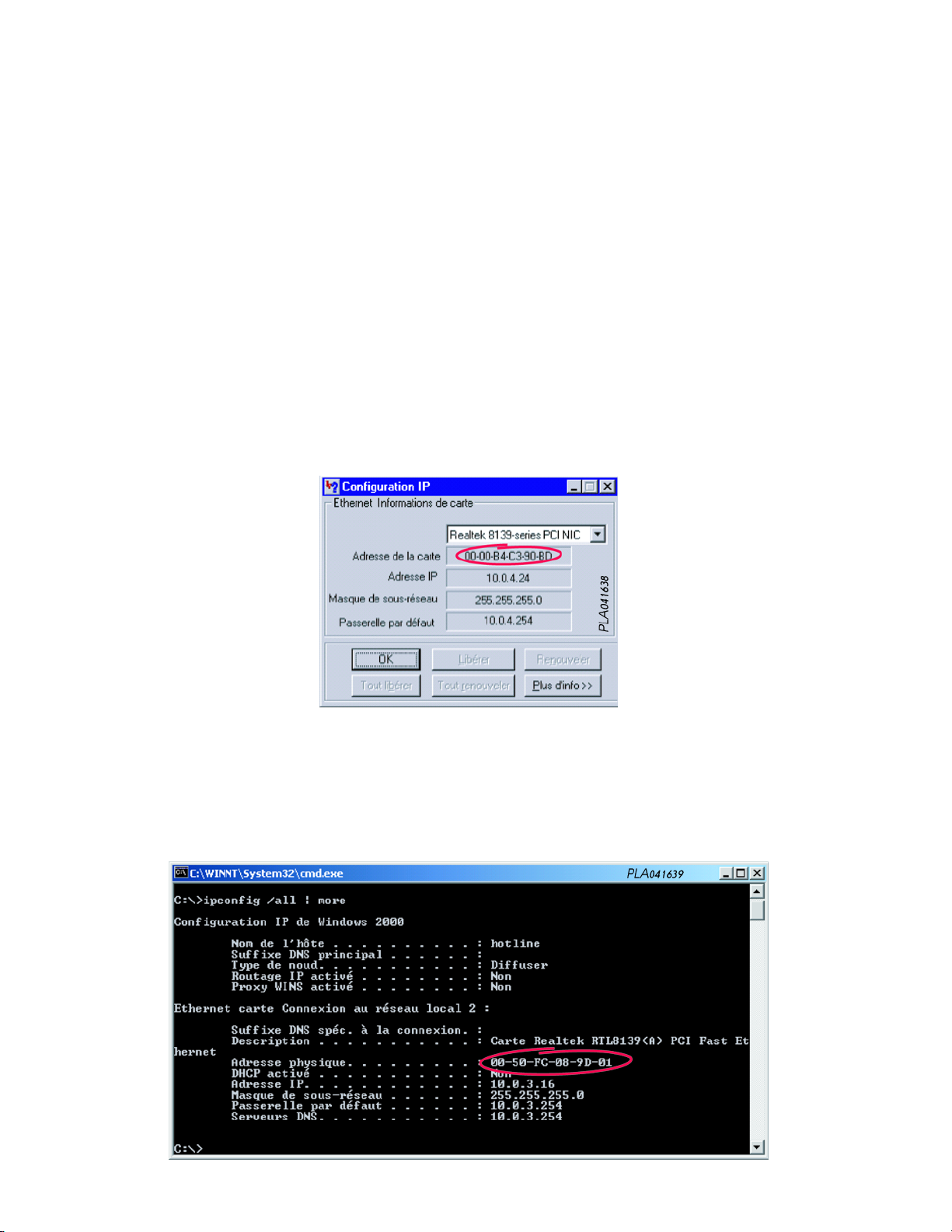
Windows 95/ 98/Me
– Start run Enter "winipcfg" to view the "IP Configuration" table.
– Scroll down until you find the information on your network interface card.
– The MAC address (Card address) format is "00-00-B4-C3-90-BD"
Windows NT/2000/XP
– Start run Enter "cmd" to get to the command prompt.
– C :\> ipconfig /all | more
This will display the Windows network configuration page by page.
– The MAC address (physical address) format is "00-50-FC-08-9D-01"
Page 67
13 DATA SHEETS 67
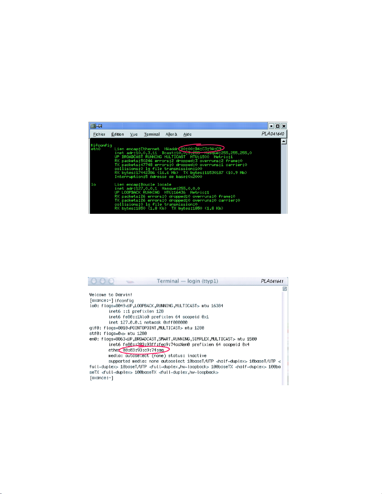
Linux
In a terminal window, enter the following command :
– $ /bin/ifconfig
– The MAC address (Hwaddr) format is "00 :00 :B4 :C3 :9A :C9"
MAC OS X
In a terminal window, enter the following command :
– [oxance :~] ifconfig
– The MAC address (ether) format is "00 :03 :93 :C9 :74 :aa"
Standalone Ethernet Device
The MAC address of a standalone Ethernet device (router, printer, controller, video/webcam,
etc.)is usually printed on the device label. If not, contact your dealer to obtain the MAC address
of your device.
Page 68
13 DATA SHEETS 68
Data Sheet 2
13.2 Updating the PLA2xxs
1 - What you need
To update the PLA200s, you need to use an FTP or HTTP server (Unix, Mac, Windows
server). We provide a description using FileZilla (open source FTP server for Windows).
FileZilla can also be used to estimate file transfer rates (client/server) with the FTP protocol.
F Before running FileZilla, make sure that no other FTP server is running on
your computer to avoid possible conflicts. If you are in doubt, ask your network
administrator.
Configuration Used :
– Windows 2000 professional (IP address 192.168.1.16)
– FileZilla Server version 0_8_8 (23 November 2003) http ://sourceforge.net/projects/fileZilla/
– Access point PLA200 with factory set IP address : 192.168.1.251
The new firmware must be decompressed and copied to a folder on your hard disk. For
example " c :\temp\update ".
Once the archive is decompressed, you should have 4 files (linuz_br, romdisk_br.img,
update.hdr, usr_br.jffs).
F If you change or rename the files, the update may not be successful.
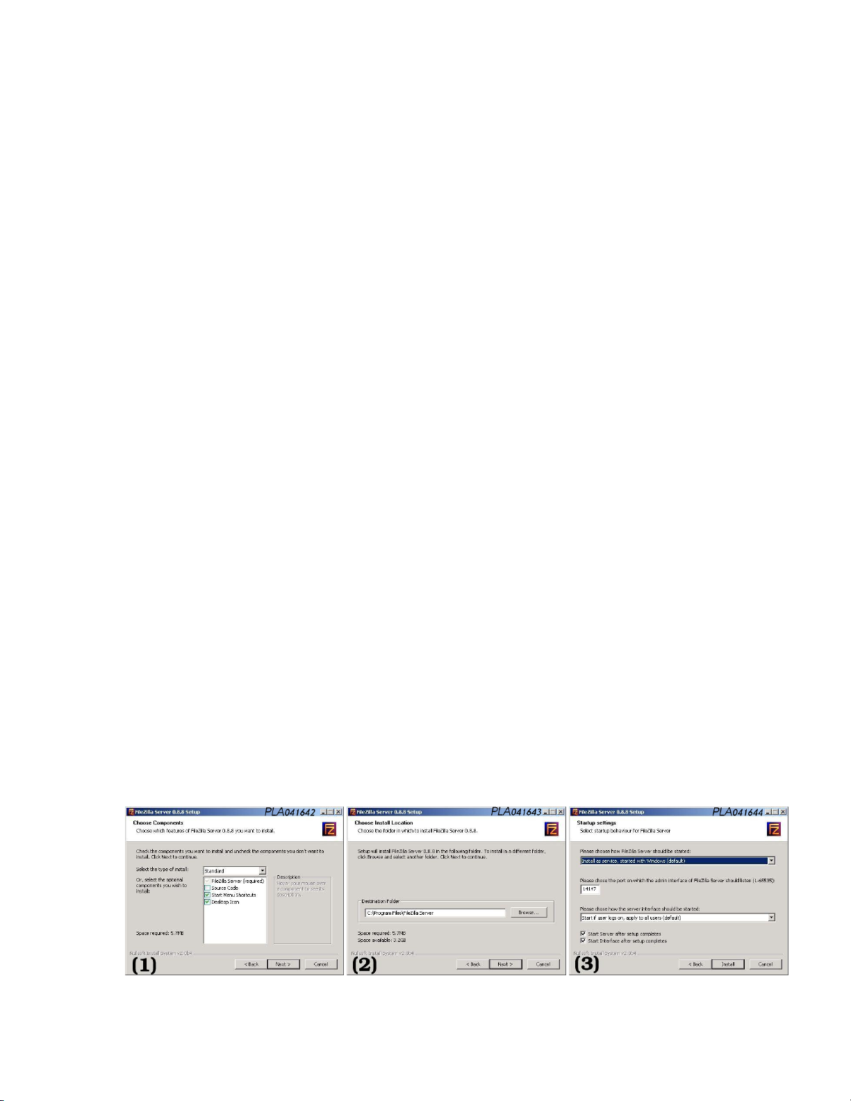
2 - Installing and configuring the FileZilla_Server software
Installation et configuration du logiciel FileZilla_Server
(1) Leave the default options unchanged and click on <Next>
(2) Choose the destination directory and click <Next>
(3) Leave the default options unchanged and click on <Next>
Page 69
13 DATA SHEETS 69
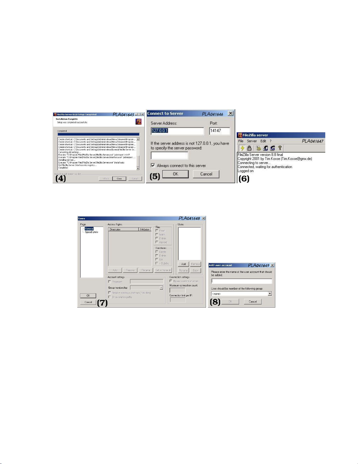
(4) Once the installation is complete, close the application <close>
(5) Leave the default <Server Address> unchanged, check <Always connect to this
server> and click <OK>
(6) This takes you to the FileZilla server configuration inter face
(7) Menu "Edit - Users" In the column "Users" -> click on <Add>
(8) Enter an identifier (for example : oxance)
(9) In the column "Access Rights" :
- Click on <Add> go to your transfer directory (C :\temp\update)
- Assign the following rights :
Files :<Read, Write>
Directories : <List, +Subdirs>
In "Account settings" :
- Check Password and enter a password (for example : oxance)
- Check <Show relative paths>
Page 70
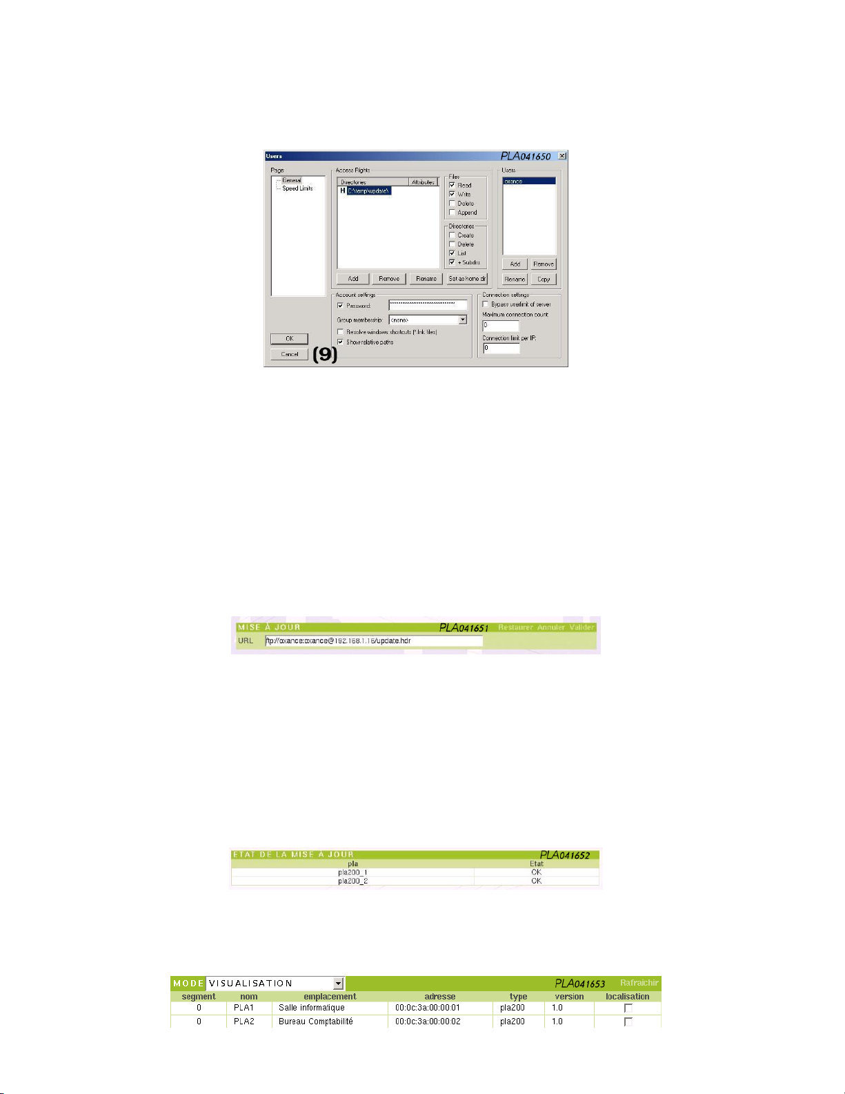
13 DATA SHEETS 70
The FileZilla_Server configuration is complete. You can now update the PLA200s. To
learn more about FileZilla, please visit their website http ://sourceforge.net/projects/fileZilla/
3 - Connecting to the access point PLA200 to perform the update.
Connect to the PLA from a web browser. This is what we call the access point PLA. This
PLA will be the starting point for the update, and all of other the PLAs detected will be
updated via the powerline.
Menu “Global Network - Setup - Update”
Enter the following URL address :
ftp ://login :password@adresseipserveurftp/update.hdr
Example : ftp ://[email protected]/update.hdr
Progress is shown in real time (in queue - running - OK).
If "failed" appears, the update was unsuccessful and the device still has the previous
version installed. In this case, the update must be repeated. Updated devices will remain unchanged. If the update fails repeatedly on one PLA, try to connect it directly to
your computer.
You can view transfers in the FileZilla log file. (see page 71 : FileZilla log).
The last message tells you that the devices will restart with the new version.
Go to the "Global Network - Products List" menu to make sure that the new version is
displayed.
Page 71

13 DATA SHEETS 71
4 - FileZilla log file for a PLA2xx update
(000008) 04/12/2003 14 :53 :31 - (not logged in) (192.168.1.251)> Connected, sending welcome message...
(000008) 04/12/2003 14 :53 :31 - (not logged in) (192.168.1.251)> 220-FileZilla Server version 8.8 final
(000008) 04/12/2003 14 :53 :31 - (not logged in) (192.168.1.251)> 220-written by T im Kosse ([email protected])
(000008) 04/12/2003 14 :53 :31 - (not logged in) (192.168.1.251)> 220 Please visit http ://sourceforge.net/projects/filezilla/
(000008) 04/12/2003 14 :53 :32 - (not logged in) (192.168.1.251)> USER oxance
(000008) 04/12/2003 14 :53 :32 - (not logged in) (192.168.1.251)> 331 Password r equired for oxance
(000008) 04/12/2003 14 :53 :32 - (not logged in) (192.168.1.251)> PASS ******
(000008) 04/12/2003 14 :53 :32 - oxance (192.168.1.251)> 230 Logged on
(000008) 04/12/2003 14 :53 :32 - oxance (192.168.1.251)> CDUP
(000008) 04/12/2003 14 :53 :32 - oxance (192.168.1.251)> 200 CDUP successful. "/" is current directory.
(000008) 04/12/2003 14 :53 :32 - oxance (192.168.1.251)> TYPE I
(000008) 04/12/2003 14 :53 :32 - oxance (192.168.1.251)> 200 Type set to I
(000008) 04/12/2003 14 :53 :32 - oxance (192.168.1.251)> SIZE /update.hdr
(000008) 04/12/2003 14 :53 :32 - oxance (192.168.1.251)> 213 294
(000008) 04/12/2003 14 :53 :32 - oxance (192.168.1.251)> PASV
(000008) 04/12/2003 14 :53 :32 - oxance (192.168.1.251)> 227 Entering Passive Mode (192,168,1,16,4,34)
(000008) 04/12/2003 14 :53 :32 - oxance (192.168.1.251)> RETR /update.hdr
(000008) 04/12/2003 14 :53 :32 - oxance (192.168.1.251)> 150 Connection accepted
(000008) 04/12/2003 14 :53 :32 - oxance (192.168.1.251)> 226 Transfer OK
(000008) 04/12/2003 14 :53 :32 - oxance (192.168.1.251)> QUIT
(000008) 04/12/2003 14 :53 :32 - oxance (192.168.1.251)> 221 Goodbye
(000008) 04/12/2003 14 :53 :32 - oxance (192.168.1.251)> disconnected.
(000009) 04/12/2003 14 :53 :38 - (not logged in) (192.168.1.251)> Connected, sending welcome message...
(000009) 04/12/2003 14 :53 :38 - (not logged in) (192.168.1.251)> 220-FileZilla Server version 8.8 final
(000009) 04/12/2003 14 :53 :38 - (not logged in) (192.168.1.251)> 220-written by T im Kosse ([email protected])
(000009) 04/12/2003 14 :53 :38 - (not logged in) (192.168.1.251)> 220 Please visit http ://sourceforge.net/projects/filezilla/
(000009) 04/12/2003 14 :53 :38 - (not logged in) (192.168.1.251)> USER oxance
(000009) 04/12/2003 14 :53 :38 - (not logged in) (192.168.1.251)> 331 Password r equired for oxance
(000009) 04/12/2003 14 :53 :38 - (not logged in) (192.168.1.251)> PASS ******
(000009) 04/12/2003 14 :53 :38 - oxance (192.168.1.251)> 230 Logged on
(000009) 04/12/2003 14 :53 :38 - oxance (192.168.1.251)> CDUP
(000009) 04/12/2003 14 :53 :38 - oxance (192.168.1.251)> 200 CDUP successful. "/" is current directory.
(000009) 04/12/2003 14 :53 :38 - oxance (192.168.1.251)> TYPE I
(000009) 04/12/2003 14 :53 :38 - oxance (192.168.1.251)> 200 Type set to I
(000009) 04/12/2003 14 :53 :38 - oxance (192.168.1.251)> SIZE /linuz_br
(000009) 04/12/2003 14 :53 :38 - oxance (192.168.1.251)> 213 397144
(000009) 04/12/2003 14 :53 :38 - oxance (192.168.1.251)> PASV
(000009) 04/12/2003 14 :53 :38 - oxance (192.168.1.251)> 227 Entering Passive Mode (192,168,1,16,4,35)
(000009) 04/12/2003 14 :53 :38 - oxance (192.168.1.251)> RETR /linuz_br
(000009) 04/12/2003 14 :53 :38 - oxance (192.168.1.251)> 150 Connection accepted
(000009) 04/12/2003 14 :53 :42 - oxance (192.168.1.251)> 226 Transfer OK
(000009) 04/12/2003 14 :53 :43 - oxance (192.168.1.251)> QUIT
(000009) 04/12/2003 14 :53 :43 - oxance (192.168.1.251)> 221 Goodbye
(000009) 04/12/2003 14 :53 :43 - oxance (192.168.1.251)> disconnected.
(000010) 04/12/2003 14 :53 :54 - (not logged in) (192.168.1.251)> Connected, sending welcome message...
(000010) 04/12/2003 14 :53 :54 - (not logged in) (192.168.1.251)> 220-FileZilla Server version 8.8 final
(000010) 04/12/2003 14 :53 :54 - (not logged in) (192.168.1.251)> 220-written by T im Kosse ([email protected])
(000010) 04/12/2003 14 :53 :54 - (not logged in) (192.168.1.251)> 220 Please visit http ://sourceforge.net/projects/filezilla/
(000010) 04/12/2003 14 :53 :54 - (not logged in) (192.168.1.251)> USER oxance
(000010) 04/12/2003 14 :53 :54 - (not logged in) (192.168.1.251)> 331 Password r equired for oxance
(000010) 04/12/2003 14 :53 :54 - (not logged in) (192.168.1.251)> PASS ******
(000010) 04/12/2003 14 :53 :54 - oxance (192.168.1.251)> 230 Logged on
(000010) 04/12/2003 14 :53 :54 - oxance (192.168.1.251)> CDUP
(000010) 04/12/2003 14 :53 :54 - oxance (192.168.1.251)> 200 CDUP successful. "/" is current directory.
(000010) 04/12/2003 14 :53 :54 - oxance (192.168.1.251)> TYPE I
(000010) 04/12/2003 14 :53 :54 - oxance (192.168.1.251)> 200 Type set to I
(000010) 04/12/2003 14 :53 :54 - oxance (192.168.1.251)> SIZE /romdisk_br.img
(000010) 04/12/2003 14 :53 :54 - oxance (192.168.1.251)> 213 914432
(000010) 04/12/2003 14 :53 :54 - oxance (192.168.1.251)> PASV
(000010) 04/12/2003 14 :53 :54 - oxance (192.168.1.251)> 227 Entering Passive Mode (192,168,1,16,4,36)
(000010) 04/12/2003 14 :53 :54 - oxance (192.168.1.251)> RETR /romdisk_br.img
(000010) 04/12/2003 14 :53 :54 - oxance (192.168.1.251)> 150 Connection accepted
(000010) 04/12/2003 14 :54 :06 - oxance (192.168.1.251)> 226 Transfer OK
(000010) 04/12/2003 14 :54 :06 - oxance (192.168.1.251)> QUIT
(000010) 04/12/2003 14 :54 :06 - oxance (192.168.1.251)> 221 Goodbye
(000010) 04/12/2003 14 :54 :06 - oxance (192.168.1.251)> disconnected.
(000011) 04/12/2003 14 :54 :11 - (not logged in) (192.168.1.251)> Connected, sending welcome message...
(000011) 04/12/2003 14 :54 :11 - (not logged in) (192.168.1.251)> 220-FileZilla Server version 8.8 final
(000011) 04/12/2003 14 :54 :11 - (not logged in) (192.168.1.251)> 220-written by T im Kosse ([email protected])
(000011) 04/12/2003 14 :54 :11 - (not logged in) (192.168.1.251)> 220 Please visit http ://sourceforge.net/projects/filezilla/
(000011) 04/12/2003 14 :54 :12 - (not logged in) (192.168.1.251)> USER oxance
(000011) 04/12/2003 14 :54 :12 - (not logged in) (192.168.1.251)> 331 Password r equired for oxance
(000011) 04/12/2003 14 :54 :12 - (not logged in) (192.168.1.251)> PASS ******
(000011) 04/12/2003 14 :54 :12 - oxance (192.168.1.251)> 230 Logged on
(000011) 04/12/2003 14 :54 :12 - oxance (192.168.1.251)> CDUP
(000011) 04/12/2003 14 :54 :12 - oxance (192.168.1.251)> 200 CDUP successful. "/" is current directory.
(000011) 04/12/2003 14 :54 :12 - oxance (192.168.1.251)> TYPE I
(000011) 04/12/2003 14 :54 :12 - oxance (192.168.1.251)> 200 Type set to I
(000011) 04/12/2003 14 :54 :12 - oxance (192.168.1.251)> SIZE /usr_br.jf fs
(000011) 04/12/2003 14 :54 :12 - oxance (192.168.1.251)> 213 237588
(000011) 04/12/2003 14 :54 :12 - oxance (192.168.1.251)> PASV
(000011) 04/12/2003 14 :54 :12 - oxance (192.168.1.251)> 227 Entering Passive Mode (192,168,1,16,4,37)
(000011) 04/12/2003 14 :54 :12 - oxance (192.168.1.251)> RETR /usr_br.jf fs
(000011) 04/12/2003 14 :54 :12 - oxance (192.168.1.251)> 150 Connection accepted
(000011) 04/12/2003 14 :54 :14 - oxance (192.168.1.251)> 226 Transfer OK
(000011) 04/12/2003 14 :54 :15 - oxance (192.168.1.251)> QUIT
(000011) 04/12/2003 14 :54 :15 - oxance (192.168.1.251)> 221 Goodbye
Page 72
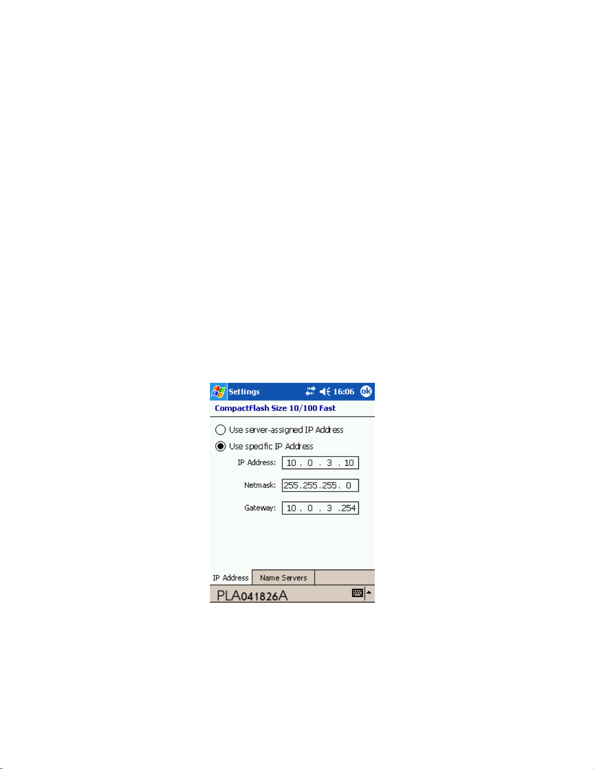
13 DATA SHEETS 72
DataSheet 3
13.3 Setup and optimize a PLC network with a PocketPC
A PocketPC can be used to setup and diagnose the PLC network.
1- What you need
- A pocket PC
- Microsoft PocketPC 2003 (Windows CE 4.20)
- A compact flash slot
- An Ethernet compact flash adaptater
2- IP configuration
Example :
- PLA200 setup with 10.0.3.200
- Pocket PC setup with 10.0.3.10/255.255.255.0
Setings/IP address :
Page 73
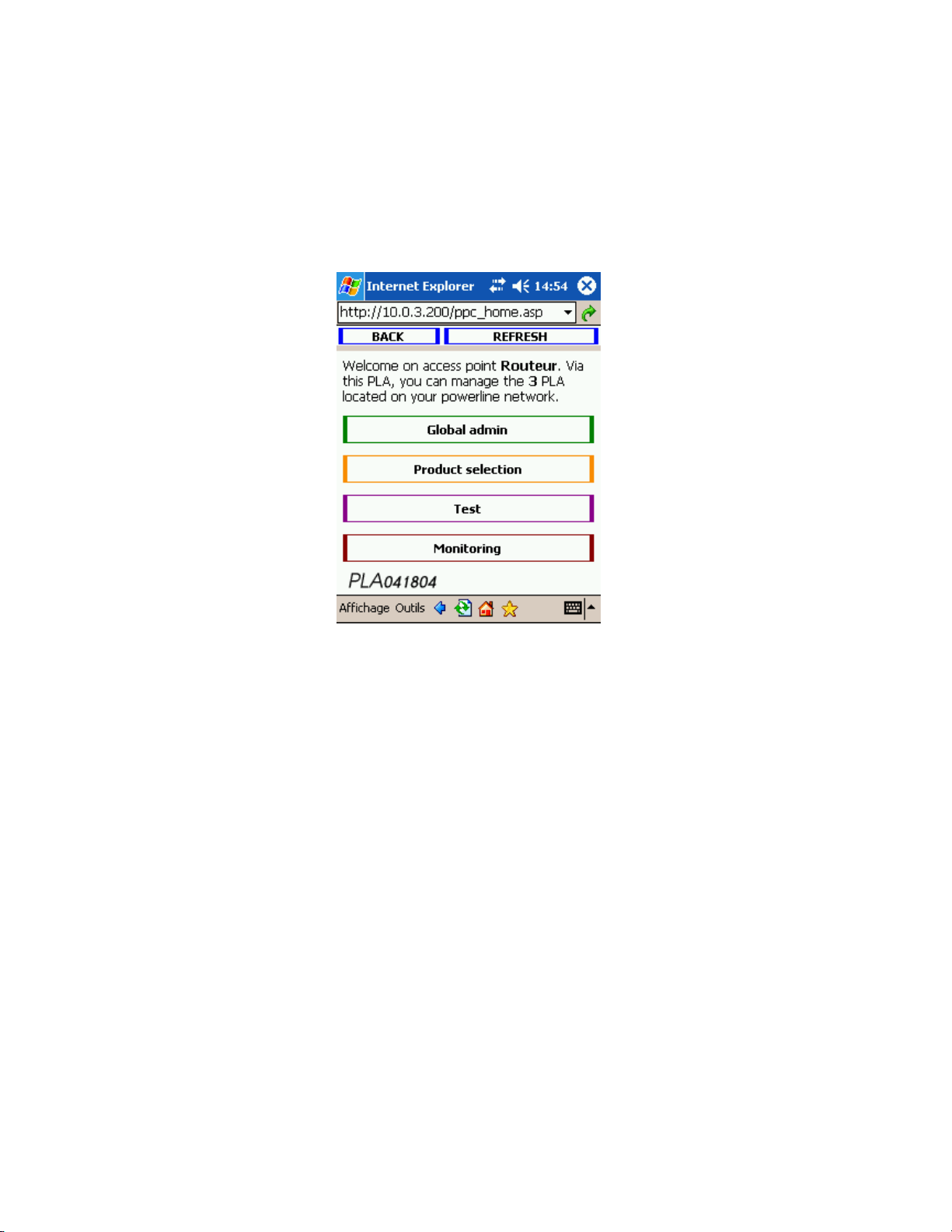
13 DATA SHEETS 73
3 - Graphical setup
Enter the IP address of the PLA200 in the address bar of Internet Explorer.
The device’s Home page comes up :
Global admin : in relation with all of the PLA2xx detected on the powerline network.
You can manage PLC password and setup the quality unit (raw, tcp, internal, %).
Product selection : directly related to the selected PLA2xx.
You can :
- quickly find the physical location of your device (locate).
- change name, location, segment, MTU and PLC password.
- see the quality table in relation with others PLA.
- see the routing table (with relay if necessary).
Test : allows to calculate the bandwith (Mb/s) beetwen the Access point PLA and another remote PLA.
Monitoring : allows to graphically control the quality fluctuations beetwen 2 PLA along
the time.
Page 74
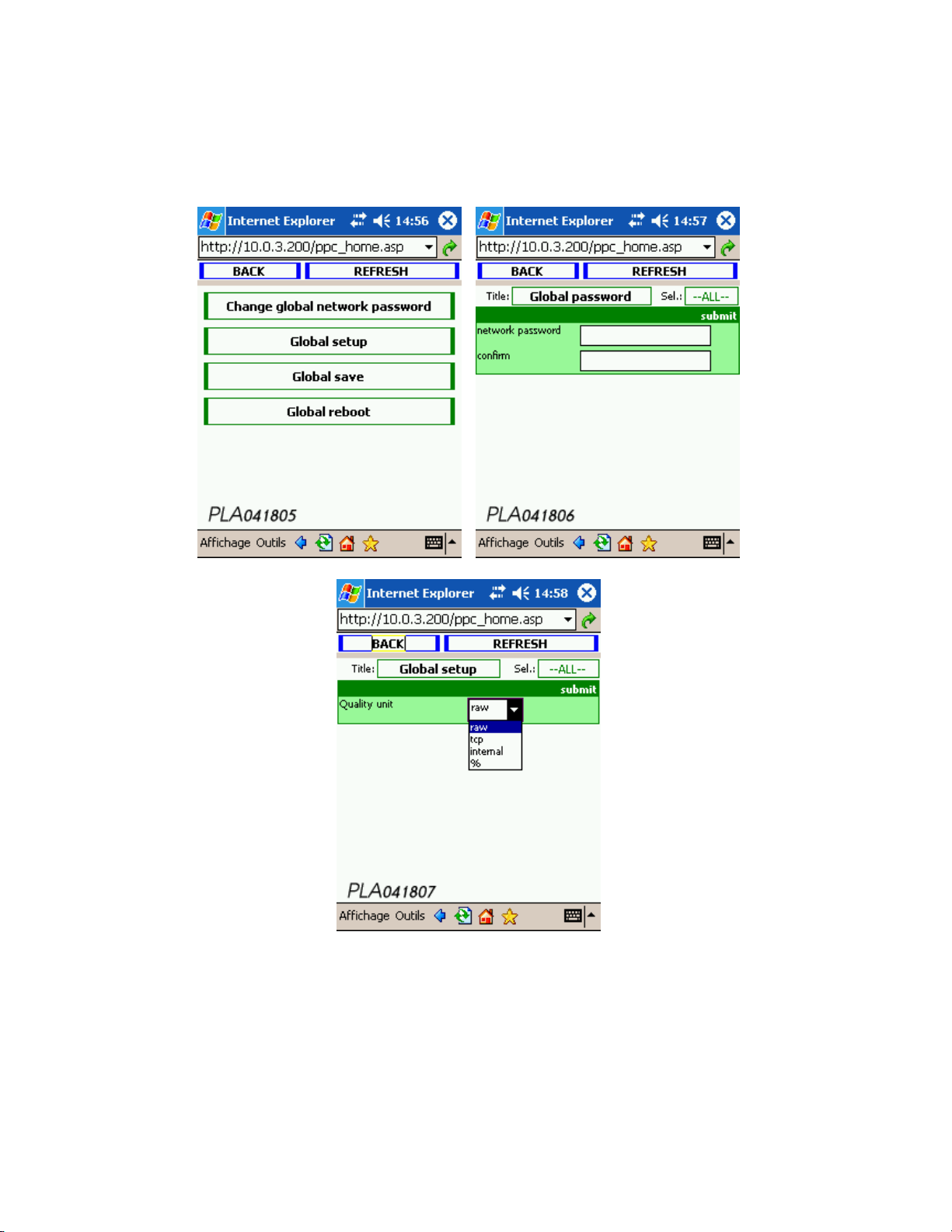
13 DATA SHEETS 74
3.1- Global admin
Page 75
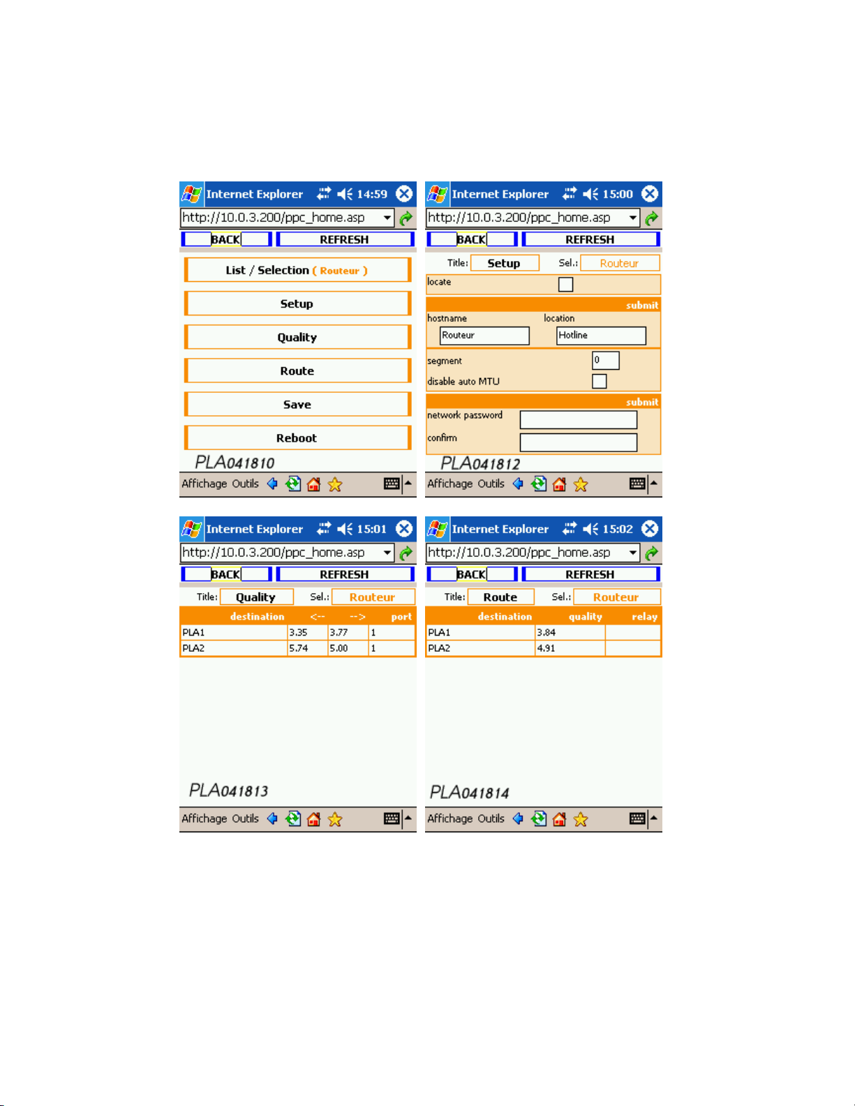
13 DATA SHEETS 75
3.2- Product selection
Page 76
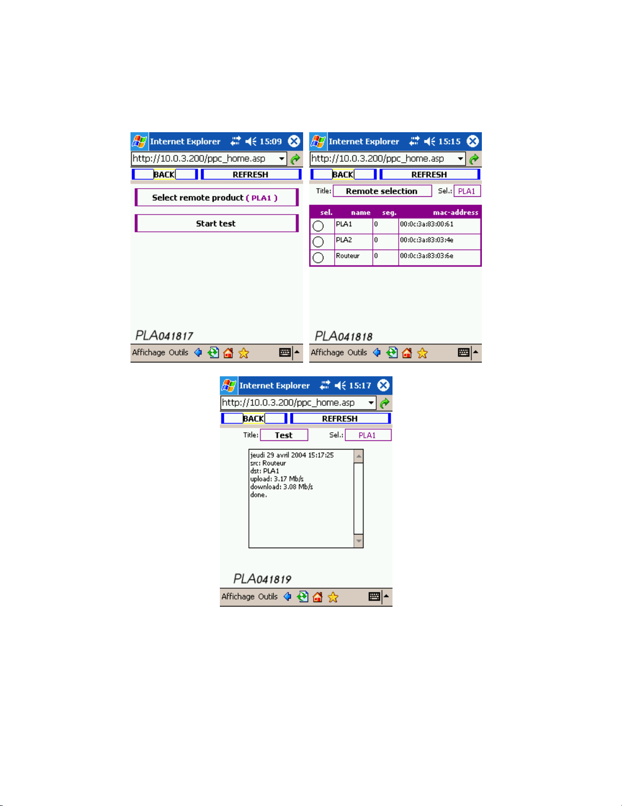
13 DATA SHEETS 76
3.3- Test
Page 77
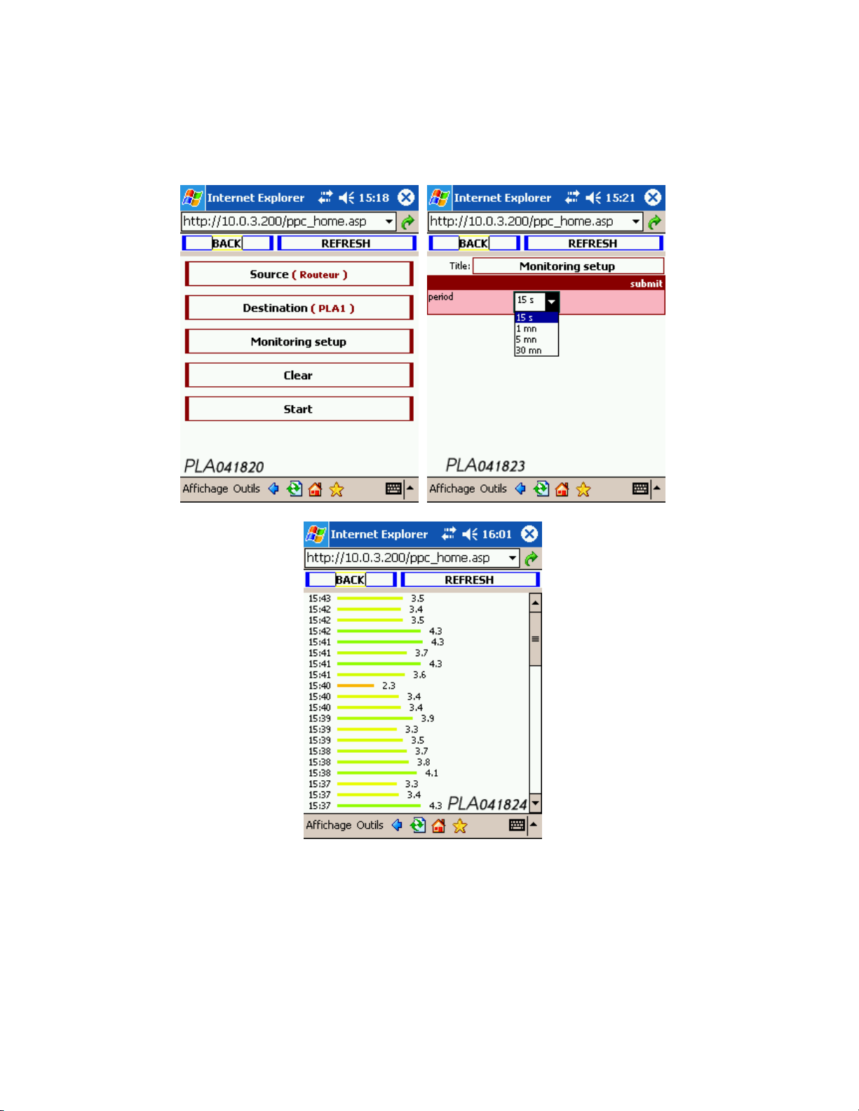
13 DATA SHEETS 77
3.4- Monitoring
Page 78

14 GLOSSAIRE 78
14 Glossaire
802.x
IEEE standards defining local network protocols.
ADAPTER
A hardware interface between a device and the network. In this case they are PLCnet TM adapters.
IP ADDRESS
Address assigned to a server in the form w.x.y.z (w, x, y, z ranging from 0 to 255 inclusive). IP
addressing is used identify and locate any device connected to the Internet. In a larger sense on
local networks, the IP address enables the devices to communicate with one another.
MAC ADDRESS
The hardware address of a device connected to a shared medium.
CSMA/CA (Carrier Sense Multiple Access with Collision A voidance)
Method of accessing a local network, in which a device that wants to transmit verifies that another
device is not already transmitting at the same time (in which case a transmission would generate
a collision). In the collision avoidance (CA) method, verification takes place prior to transmission,
in order to avoid a collision. This method is effective if the time allocated is short compared to the
packet length, and if there are a small number of stations.
CSMA/CD (Carrier Sense Multiple Access with Collision Detection)
Method of accessing a local network, in which a device that wants to transmit verifies that ano-
ther device is not already transmitting at the same time (in which case a transmission would
generate a collision). During the transmission the device checks for collisions. If a collision is
detected, the device transmits its message again after waiting for a random interval.
DHCP (Dynamic Host Configuration Protocol)
This is a protocol that assigns a network configuration dynamically when a computer connects
to the network. You simply tell the computer to find an IP address by DHCP. This simplifies the
network administration.
ETHERNET
Local network standard designed originally by Xerox, DEC and Intel, today standardised by ISO.
It normally functions at 10 Mbps (Mbits per second) using coaxial cabling, bus topology and
CSMA-CD.
HUB
Multi-repeater : hardware/software unit linking a number of stations to a local network. A hub is
the central signal distributor, to which all the devices of a local network are connected. The hub
synchronises and retransmits data signals as a repeater, but also has other capabilities such as
network management. A hub usually has multiple ports in order to link several devices, creating
a star topology.
IEEE (Institute of Electrical and Electronic Engineers)
US Association of Electrical and Electronic Engineers that plays an important role as a forum for
research and discussion on standardization. It played an important role in standardizing local
networks, with standard 802.3 (Ethernet), 802.4 (token bus) and 802.5 (token ring). IEEE website : http ://www.ieee.org
Page 79

14 GLOSSAIRE 79
ISO (International Standard Organisation)
International organisation founded in 1946 under the auspices of the UN, in charge of standar-
dization in many areas, including information technology, networks, and communications. A list
of ISO standards : http ://www.iso.ch/
MDI (Medium-Dependent Interface)
MDIX (Medium-Dependent Interface X)
A physical and electrical interface used in an Ethernet network to connect a device interface to
the network cable. It is the interface proposed by an interconnection device (hub, bridge or switch)
to connect to another device (computer or other interconnection device). An MDI port connects
to a MDIX port via a straight-through twisted-pair cable, whereas an MDI-MDI or MDIX-MDIX
connection is made via a crossover cable.
OSI (Open Systems Interconnection)
Reference model defined by the ISO, composed of seven layers (called abstraction layers), each
specifying the functions and protocols required for two nodes to communicate using the under lying network infrastructure (physical medium, switches, routers, bridges, multiplexers, intermediate nodes). Application- Presentation - Session- Transport- Network- Datalink- Physical. This
model was developed by the ISO as a framework for international standards in heterogeneous
computer network architecture. When a layer transmits its data to the underlying layer, the data
are said to be encapsulated.
RJ45
Type of connector used in local networks, in particular UTP twisted pair wiring, for 10Base-T and
100Base-T Ethernet. It is used with 8-wire, 8-pin cables, only 4 of which are connected. On this
type of network, the maximum distance between the hub and a machine must not exceed a total
of 100 m.
ROUTER
A device that forwards data traffic via a network (OSI level 3).
TCP/IP (Transmission Control Protocol / Internet Protocol)
Network management protocol composed of a series of protocols operating together. The initial
purpose was to create a protocol capable of connecting dissimilar computers across a network,
by taking multiple routes to r each a final destination.
Page 80

15 NOTE 80
15 Note
Oxance and PLCnetTMare registered trademarks of Oxance. All other trademarks used in the document are proprietary to their r espective owners. The
descriptions and photos are not contractual. With a view to continually improving its products, Oxance reserves the right to modify the characteristics
of the products at any time and without prior notice. Warning : no part of this
document may be reproduced without the prior consent of Oxance.
 Loading...