

Page 1

SDS Series
Smart Digital Storage Oscilloscopes
Quick Guide
Test Equipment Depot - 800.517.8431 - 99 Washington Street Melrose, MA 02176
TestEquipmentDepot.com
Page 2

Nov. 2014 edition V1.6.3
Copy Right in this Manual © L illiput Company. All rights Reserved.
The Lilliput's products are under the protection of the patent rights in America and other countries,
including ones which have already obtained the patent rights and those which are applying for. The
information in this manual will replace all that in the materials published originally.
The information in this manual was correct at the time of printing. However, OWON will continue to
improve products and reserves the rights to changes specification at any time without notice.
OWON is the registered trademark of the Lilliput Company.
Page 3

Test Equipment Depot - 800.517.8431 - 99 Washington Street Melrose, MA 02176
TestEquipmentDepot.com
Page 4

i
Table of Contents
1. General Safety Requirements .......................................................................................... 1
2. Safety Terms and Symbols ............................................................................................... 2
3. Quick Start ....................................................................................................................... 4
Introduction to the Structure of the Oscilloscope ..................................................................... 4
Front Panel ............................................................................................................................................... 4
Left Side Panel ......................................................................................................................................... 5
Right Side Panel ....................................................................................................................................... 5
Rear Panel ................................................................................................................................................ 6
Control (key and knob) Area .................................................................................................................... 7
User Interface Introduction ........................................................................................................ 8
How to Implement the General Inspection ............................................................................. 10
How to Implement the Function Inspection ............................................................................ 10
How to Implement the Probe Compensation .......................................................................... 11
How to Set the Probe Attenuation Coefficient ........................................................................ 12
How to Use the Probe Safely..................................................................................................... 13
How to Implement Self-calibration .......................................................................................... 13
Introduction to the Vertical System ......................................................................................... 14
Introduction to the Horizontal System .................................................................................... 15
Introduction to the Trigger System ......................................................................................... 16
How to Measure Automatically ................................................................................................ 16
How to Use Autoscale ................................................................................................................ 17
4. Communication with PC ............................................................................................... 18
Using USB Port .......................................................................................................................... 18
Using LAN Port ......................................................................................................................... 19
Connect directly ..................................................................................................................................... 19
Connect through a router ........................................................................................................................ 20
Using COM Port ........................................................................................................................ 22
5. Performance parameters ............................................................................................... 23
6. Appendix ........................................................................................................................ 24
Appendix A: Enclosure ............................................................................................................. 24
Appendix B: General Care and Cleaning ............................................................................... 24
Appendix C: USB Disk Requirements ..................................................................................... 24
Page 5

1.General Safety Requirements
1
1. General Safety Requirements
Before any operations, please read the following safety precautions to avoid any
possible bodily injury and prevent this product or any other products connected
from damage. In order to avoid any contingent danger, this product is only used
within the range specified.
Only the qualified technicians can implement the maintenance.
To avoid Fire or Personal Injury:
Connect the probe correctly. The grounding end of the probe corresponds to the
grounding phase. Please don't connect the grounding end to the positive phase.
Use Proper Power Cord. Use only the power cord supplied with the product and
certified to use in your country.
Connect or Disconnect Correctly. When the probe or test lead is connected to a
voltage source, please do not connect and disconnect the probe or test lead at random.
Product Grounded. This instrument is grounded through the power cord grounding
conductor. To avoid electric shock, the grounding conductor must be grounded. The
product must be grounded properly before any connection with its input or output
terminal.
When powered by AC power, it is not allowed to measure AC power source
directly, because the testing ground and power cord ground conductor are
connected together, otherwise, it will cause short circuit.
When powered by battery, the product must ground connection. To avoid electric
shock, there must be a ground wire connect between ground and the ground port
(on the back of product panel).
Check all Terminal Ratings. To avoid fire or shock hazard, check all ratings and
markers of this product. Refer to the user's manual for more information about ratings
before connecting to the instrument.
Do not operate without covers. Do not operate the instrument with cover s or panels
removed.
Use Proper Fuse. Use only the specified type and rating fuse for this instrument.
Avoid exposed circuit. Do not touch exposed junctions and components when the
instrument is powered.
Do not operate if in any doubt. If you suspect damage occurs to the instrument, have
it inspected by qualified service personnel before further operations.
Use your Oscilloscope in a well-ventilated area. Make sure the instrument installed
with proper ventilation, refer to the user manual for more details.
Do not operate in wet conditions.
Do not operate in an explosive atmosphere.
Keep product surfaces clean and dry.
Page 6
2.Safety Terms and Symbols
2
2. Safety Terms and Symbols
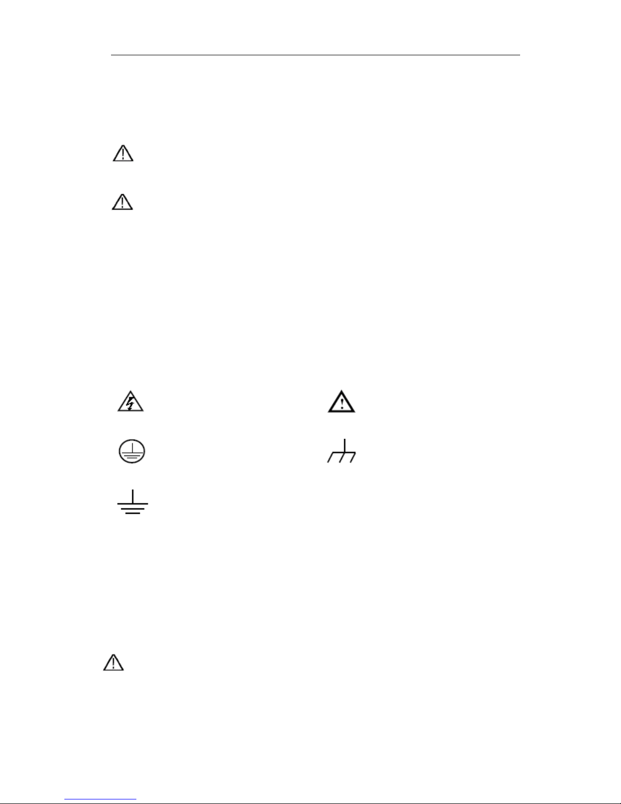
Safety Terms
Terms in this manual. The following terms may appear in this manual:
Warning: Warning indicates the conditions or practices that could result in
injury or loss of life.
Caution: Caution indicates the conditions or practices that could result in
damage to this product or other property.
Terms on the product. The following terms may appear on this product:
Danger: It indicates an injury or hazard may immediately happen.
Warning: It indicates an injury or hazard may be accessible potentially.
Caution: It indicates a potential damage to the instrument or other property might occur.
Safety Symbols
Symbols on the product. The following symbol may appear on the product:
Hazardous Voltage Refer to Manual
Protective Earth Terminal Chassis Ground
Test Ground
To avoid body damage and prevent product and connected equipment damage, carefully
read the following safety information before using the test tool. This product can only be
used in the specified applications.
Warning:
The two channels of the oscilloscope are non-isolated electrically. The channels
should adopt common basis during measuring. To prevent sh ort circui ts, the 2 probe
ground must not be connected to 2 different non-isolated DC level.
Test Equipment Depot - 800.517.8431 - 99 Washington Street Melrose, MA 02176
TestEquipmentDepot.com
Page 7
2.Safety Terms and Symbols
3
Warning:
The channels should adopt common basis during measuring. To prevent short
circuits, the 2 probe ground must not be connected to 2 different non-isolated DC
level.
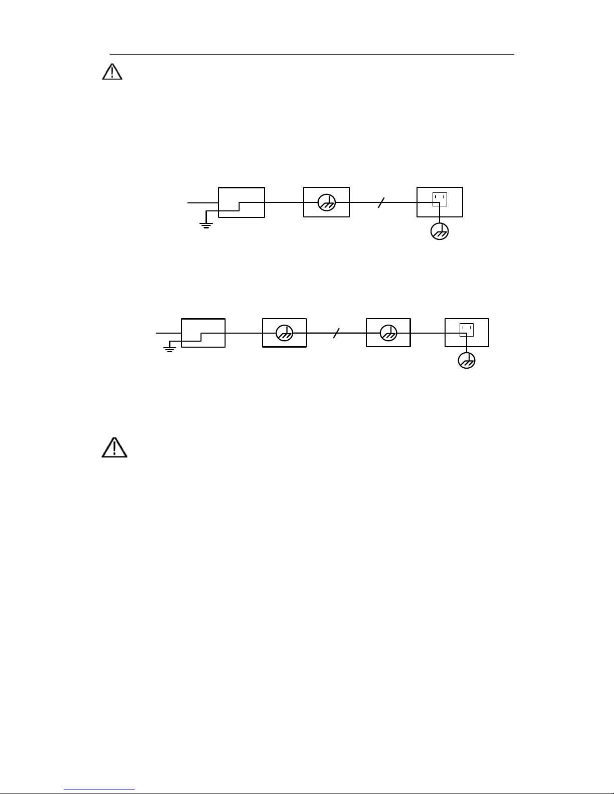
The diagram of the oscilloscope ground wire connection:
Ground Clip
Signal Input
Oscilloscope
Electrical Outlet
Probe
Power Cord
The diagram of the ground wire connection when the battery-powered oscilloscope is
connected to the AC-powered PC through the ports:
Ground Clip
Signal Input
Oscilloscope
(Battery-power)
PC Electrical OutletProbe
USB/VGA/COM/
LAN Cable
It is not allowed to measure AC power when the oscilloscope i s A C p o w e re d, o r when
the battery-powered oscilloscope is connected to the AC-powered PC through the
ports.
Warning:
To avoid fire or electrical shock
, when the oscilloscope input signal
connected
is more than
42V peak (30Vrms) or on circuits of more than
4800VA
, please take note of below items:
Only use accessory insulated voltage probes and test lead.
Check the accessori es such as probe before use and replace it if
there are any damages.
Remove probes, test leads and other accessories immediately after
use.
Remove USB cable which connects oscilloscope and computer.
Do
not apply input voltages above the rating of the instrument
because the probe tip voltage will directly transmit to the
oscilloscope. Use with caution when the probe is set as 1:1.
Do not use exposed metal BNC or banana plug conne ct or s .
Do not insert metal objects into connectors.
Page 8
3.Quick Start
4
3. Quick Start
Introduction to the Structure of the Oscilloscope
When you get a new-type oscilloscope, you should get acquainted with its front panel at
first and the SDS series digital storage oscilloscope is no exception. This chapter makes a
simple description of the operation and function of the front panel of the SDS series
oscilloscope, enabling you to be familiar with the use of the SDS series oscilloscope in the
shortest time.
Front Panel
The SDS series oscilloscope offers a simple front panel with distinct functions to users for
their completing some basic operations, in which the knobs and function pushbuttons are
included. The knobs have the functions similar to other oscilloscopes. The 5 buttons (F1 F5) in the column on the right side of the displa y screen or in the row under the display
screen (H1 - H5) are menu selection buttons, through which, you can set the different
options for the current menu. The other pushbuttons are function buttons, through which,
you can enter different function menus or obtain a specific function application directly.
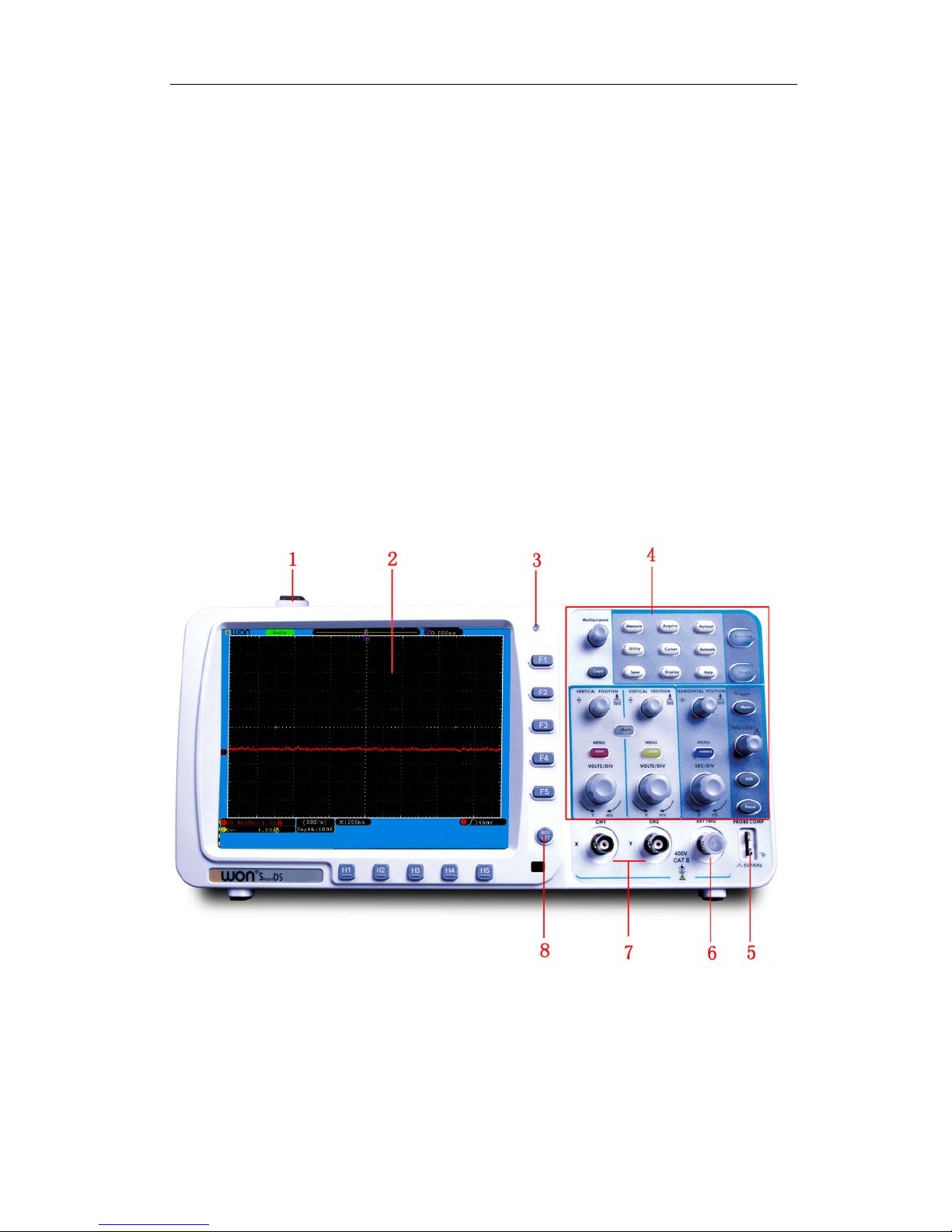
Figure 3-1 Front panel
1. Power on/off
2. Display area
3. Power indication– light
Green light: Indicating DSO connects with AC Power, and the battery is in full (if
there is battery inside DSO).
Yellow light: Indicating DSO connect with AC Power and the battery is in charging
Page 9
3.Quick Start
5
(if there is battery inside DSO)
L
ight off: Only powered by battery without connecting AC Power
4. Control (key and knob) area
5. Probe Compensation: Measurement signal (5V/1KHz) output. (The signal parameters
could be adjusted in SDS7072(V))
6. EXT Trigger Input
7. Signal Input Channel
8. Menu off
Left Side Panel
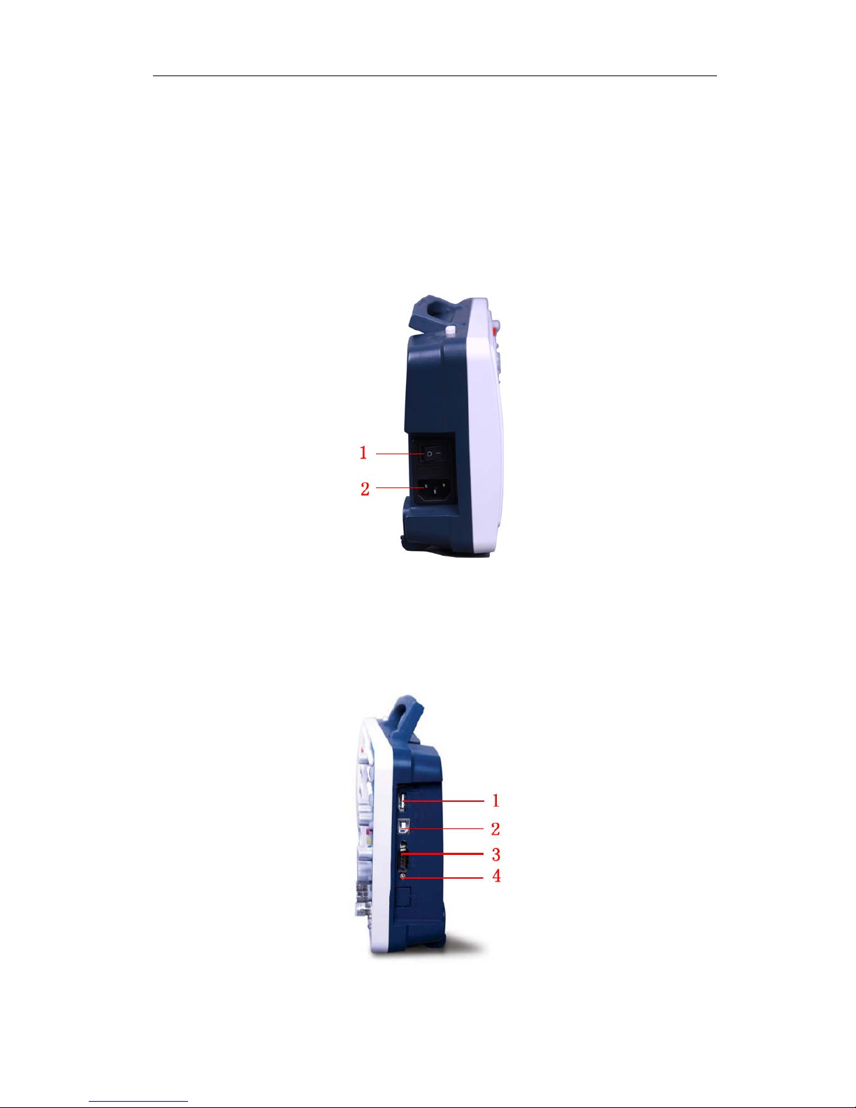
Figure 3-2 Left side panel
1. Power switch: "―" represents power ON; "○" represents power OFF.
2. AC power input jack
Right Side Panel
Figure 3-3 Right side panel
1. USB Host port: It is used to transfer data when ex ternal USB equipment connects to
Test Equipment Depot - 800.517.8431 - 99 Washington Street Melrose, MA 02176
TestEquipmentDepot.com
Page 10
3.Quick Start
6
the oscilloscope regarde d as "host device". For example: upgrading software by US B
flash disk needs to use this port.
2. USB Device port: It is used to transf er dat a when ex ternal USB eq uipm ent con nects t o
the oscilloscope re garded as "slave device". For example: to use this port when connect
PC to the oscilloscope by USB.
3. COM / VGA port (Optional): To connect the oscilloscope with external equipment as
serial port, or to connect the oscilloscope with a monitor or a projector as VGA output
(
for the model with "V")
.
4. LAN port: the network port which can be used to connect with PC.
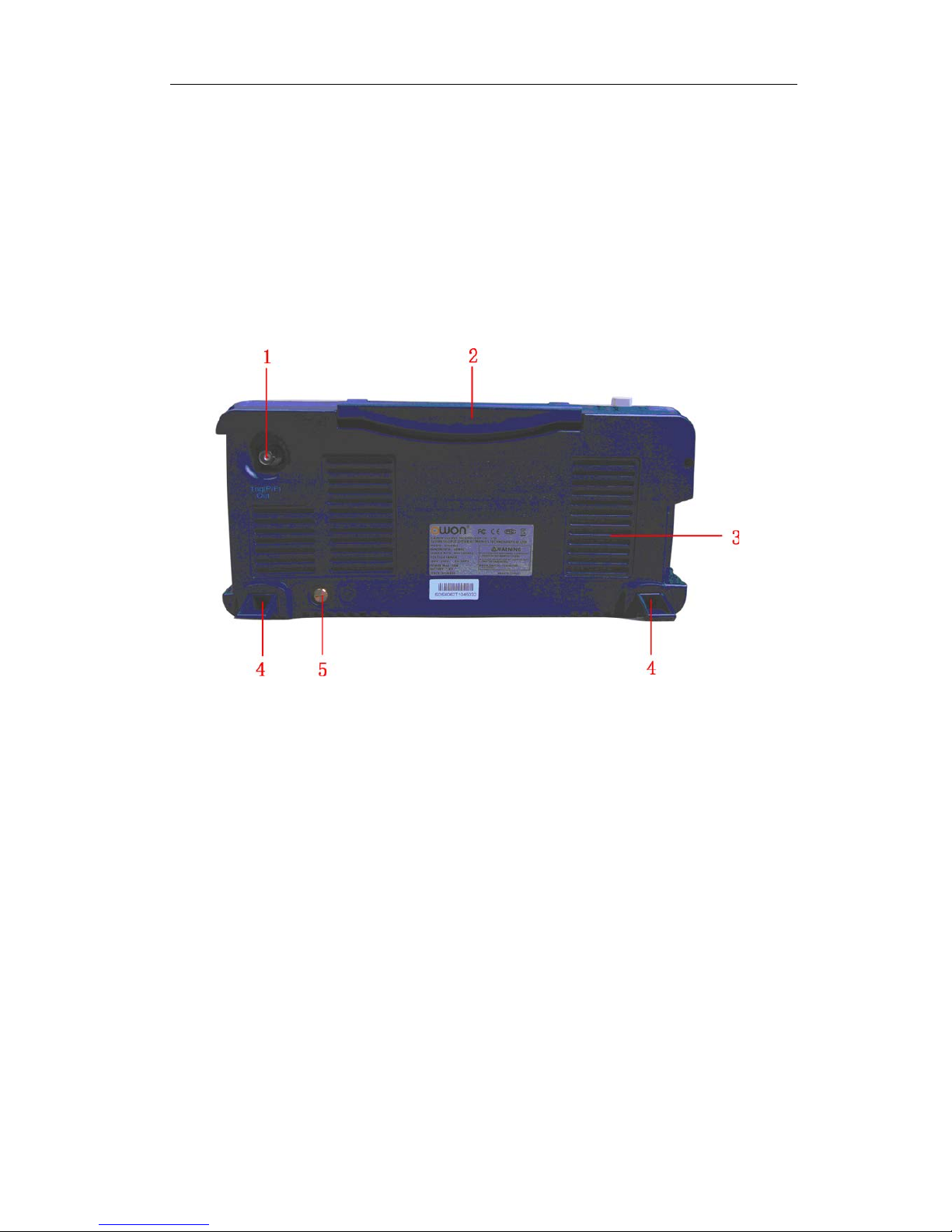
Rear Panel
Figure 3-4 Rear Panel
1. The port of trigger signal output & Pass/Fail output
2. Handle
3. Air vents
4. Foot stool (which can adjust the tilt angle of the oscilloscope)
5. Ground connection
Page 11
3.Quick Start
7
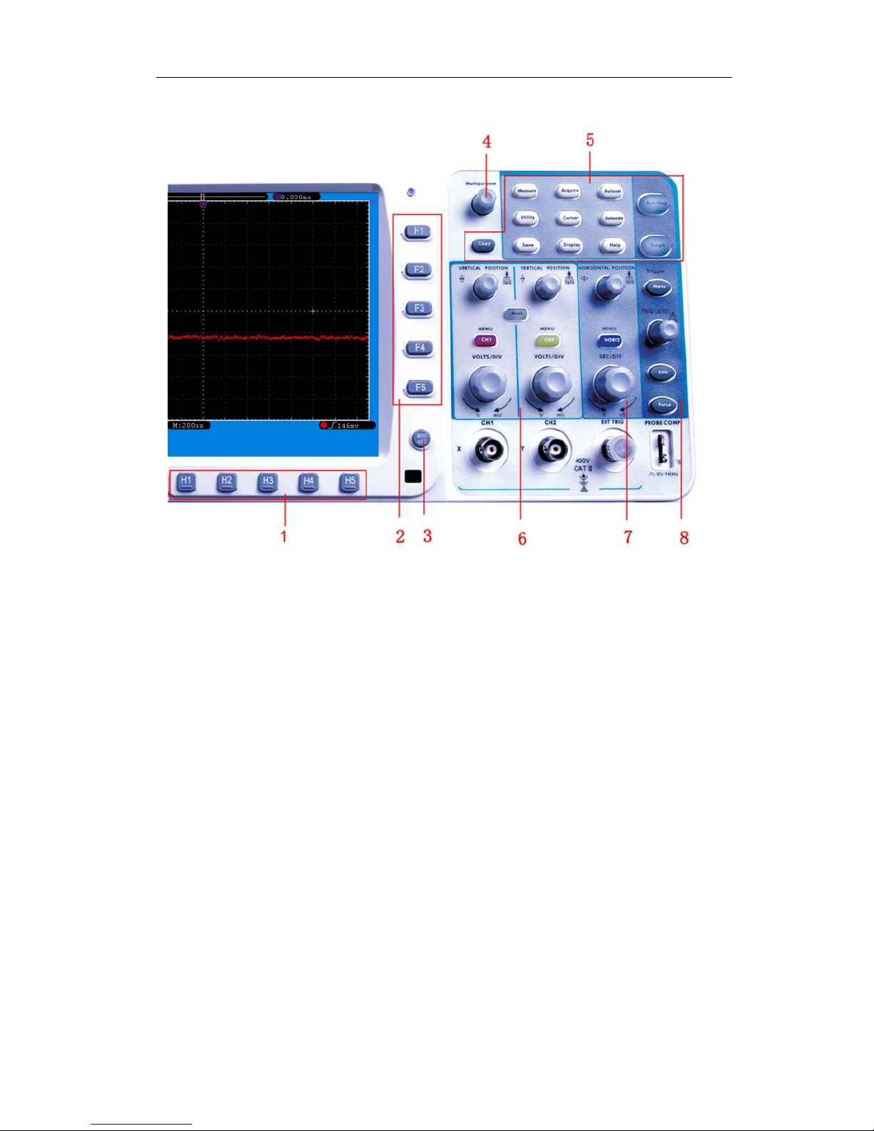
Control (key and knob) Area
Figure 3-5 Keys Overview
1. Menu option setting: H1 - H5
2. Menu option setting: F1 - F5
3. Menu off:turn off the menu
4. M knob(Multipurpose knob): when a ○M symbol appears in the menu, it indicates
you can turn the M knob to select the menu or set the value. You can press it to close
the menu on the left.
5. Function key area: Total 12 keys
6. Vertical control area with 3 keys and 4 knobs.
"CH1 MENU" and "CH2 MENU" correspond to setting menu in CH1 and CH2,
"Math" k ey refer to math menu, the math menu consists of six kinds of operations,
including CH1-CH2, CH2-CH1, CH1+CH2, CH1*CH2, CH1/CH2 and FFT. Two
"VERTICAL POSITION" knob control the vertical position of CH1/CH2, and two
"VOLTS/DIV" knob control voltage scale of CH1, CH2.
7. Horizontal control area with 1 key and 2 knobs.
"HORIZONTAL POSITION" knob control trigger position, "SEC/DIV" control time
base, "HORIZ MENU" key refer to horizontal system setting menu.
8. Trigger control area with 3 keys and 1 knob.
"TRIG LEVEL" knob is to adjust trigger voltage. Other 3 keys refer to trigger system
setting.
Page 12
3.Quick Start
8
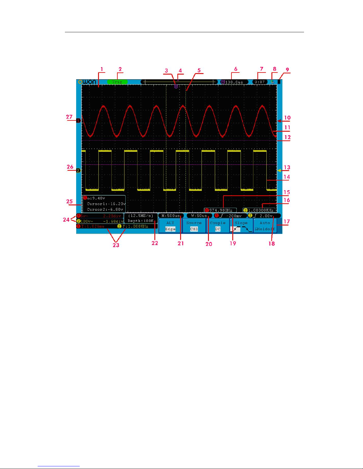
User Interface Introduction
Figure 3-6 Illustrative Drawing of Display Interfaces
1. Waveform Display Area.
2. The state of trigger, including:
Auto: Automatic mode and acquire waveform without triggering.
Trig: Trigger detected and acquire waveform.
Ready: Pre-triggered data captured and ready for a trigger.
Scan: Capture and display the waveform continuously.
Stop: Data acquisition stopped.
3. The purple T pointer indicates the horizontal position for the trigger.
4. The pointer indicates the trigger position in the internal memory.
5. The two yellow dotted lines indicate the size of the viewing expanded window.
6. It shows present triggering value and displays the site of present window in
internal memory.
7. It shows setting time.
8. It indicates that there is a USB disk connecting with the oscilloscope.
9. Indicating battery power status.
10. The red pointer shows the trigger level position for CH1.
Test Eq
uipment Depot - 800.517.8431 - 99 Washington Street Melrose, MA 02176
TestEquipmentDepot.com
Page 13

3.Quick Start
9
11. The waveform of CH1.
12. The positions of two purple dotted line cursors measurements.
13. The yellow pointer shows the trigger level position for CH2.
14. The waveform of CH2.
15. The frequency of the trigger signal of CH1.
16. The frequency of the trigger signal of CH2.
17. It indicates the current function menu.
18/19. Current trigger type:
Rising edge triggering
Falling edge triggering
Video line synchronous triggering
Video field synchronous triggering
The reading shows the trigger level value of the corresponding channel.
20. The reading shows the window time base value.
21. The reading shows the setting of main time base.
22. The readings show current sample rate and the record length.
23. It indicates the measured type and value of the corresponding channel. "F" means
frequency, "T" means cycle, "V" means the average value, "Vp" the peak-peak
value, "Vk" the root-mean-square value, "Ma" the maximum amplitude value,
"Mi" the minimum amplitude value, "Vt" the Voltage value of the wav efor m 's fla t
top value, "Vb" the Volta ge value of th e wavefor m's flat base, "Va" the amplitude
value, "Os" the overshoot value, "Ps" the Preshoot value, "RT" the rise time value,
"FT" the fall time value, "PW" th e +width value, "NW" the -Width value, "+D"
the +Duty value, "-D" the -Dut y value, "PD" the Dela y A B value, "ND" the
Delay A B value, "TR" the Cycle rms, "CR" the Cursor rms, "WP" the Duty
cycle, and "RP" the Phase.
24. The readings indicate the corresponding Voltage Division and the Zero Point
positions of the channels.
The icon shows the coupling mode of the channel.
"—" indicates direct current coupling
"~" indicates AC coupling
" " indicates GND coupling
25. It is cursor measure window, showing the absolute values and the readings of the
two cursors.
26. The yellow pointer shows the grounding datum point (zero point position) of the
waveform of the CH2 channel. If the pointer is not displayed, it shows that this
channel is not opened.
27. The red pointer indicates the grounding datum point (zero point position) of the
waveform of the CH1 channel. If the pointer is not displayed, it shows that the
channel is not opened.
Page 14

3.Quick Start
10
How to Implement the General Inspection
After you get a new SDS series oscilloscope, it is recommended that you should make
a check on the instrument according to the following steps:
1. Check whether there is any damage caused by transportation.
If it is found that the packaging carton or the foamed plastic protection cushion has
suffered serious damage, do not throw it away first till the complete device and its
accessories succeed in the electrical and mechanical property tests.
2. Check the Accessories
The supplied access ories have been alr eady described in t he "Appendix A: Enclosure"
of this Manual. You can check whet her there i s any loss o f accessori es wit h referenc e
to this description. If it is found that there is any accessory lost or damaged, please get
in touch with the distributor of Lilliput responsible for this service or the Lilliput's
local offices.
3. Check the Complete Instrument
If it is found that there is damage to the appearance of the instrument, or the
instrument can not work normally, or fails in the performance t est , pleas e get i n touc h
with the Lilliput's distributor responsible for this business or the Lilliput's local offices.
If there is damage to the instrument caused by the transportation, please keep the
package. With the transportation department or the Lilliput's distributor responsible
for this business informed about it, a repairing or replacement of the instrument will
be arranged by the Lilliput.
How to Implement t he Function Inspect ion
Make a fast function check to verify the normal operation of the instrument, according
to the following steps:
1. Connect the power cord to a power source. Turn on the Power Switch
Button ― ○ on the left side (make sure the "―" side is pressed down). Then,
push down the button of the " " signal on the top.
The instrument carries out all self-check items and shows the Boot Logo. Press the
"Utility" button, then, press H1 button to get access to the "Function" menu. Turn the
M knob to select Adjust and press H3 button to select "Default". The default
attenuation coefficient set value of the probe in the menu is 10X.
2. Set the Switch in the Oscilloscope Probe as 10X and Connect the Oscilloscope
with CH1 Channel.
Align the slot in the probe with the plug in the CH1 connector BNC, and t hen tighten
the probe with rotating it to the right side.
Test Equipment Depot - 800.517.8431 - 99 Washington Street Melrose, MA 02176
TestEquipmentDepot.com
Page 15
3.Quick Start
11
Connect the probe tip and the ground clamp to the connector of the probe
compensator.
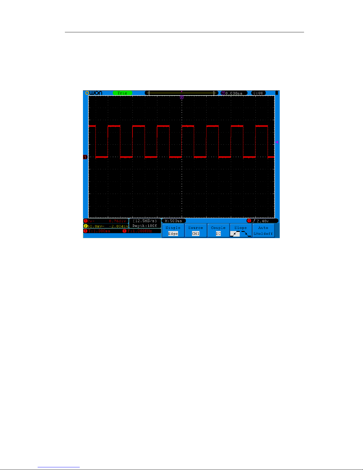
3. Press the "Autoset" Button.
The square wave of 1 KHz frequency and 5V peak-peak value will be displayed in
several seconds (see Figure 3-7).
Figure 3-7 Auto set
Check CH2 by repeating Step 2 and Step 3.
How to Implement the Probe Compensation
When connect the probe with any input channel for the first time, make this
adjustment to match the probe with the input channel. The probe which is not
compensated or presents a compensation deviation will result in the measuring error
or mistake. For adjusting the probe compensation, please carry out the following
steps:
1. Set the attenuation coefficient of the probe in the menu as 10X and that of the
switch in the probe as 10X (see "How to Set the Probe Attenuation Coefficient"
on P12), and connect the probe with the CH1 channel. If a probe hook tip is used,
ensure that it keeps in close touch with the probe. Connect the probe tip with the
signal connector o f the probe co mpensator and connect t he reference wire clamp
with the ground wire connector of the probe connector, and then press the button
"Autoset".
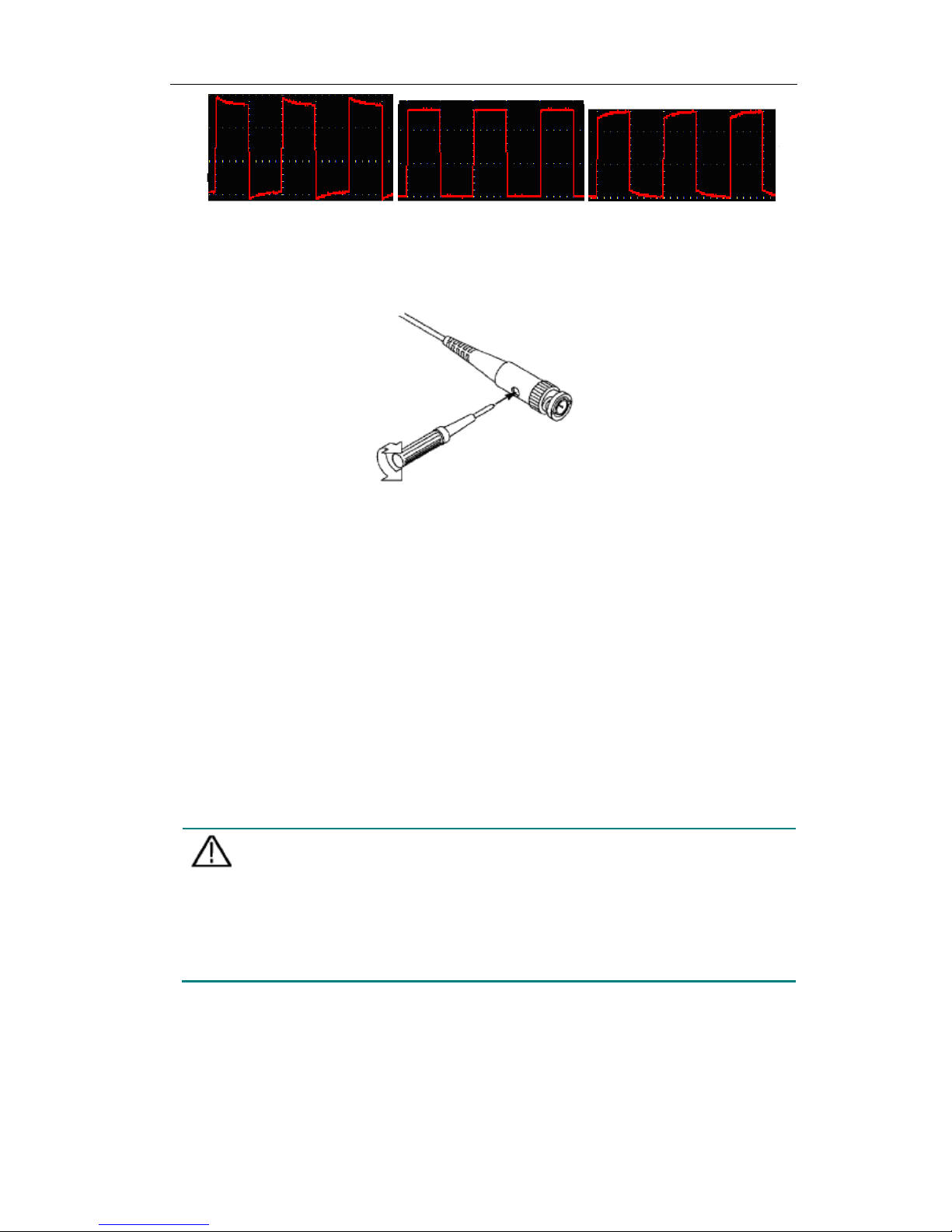
2. Check the displayed waveforms and regulate the probe till a correct
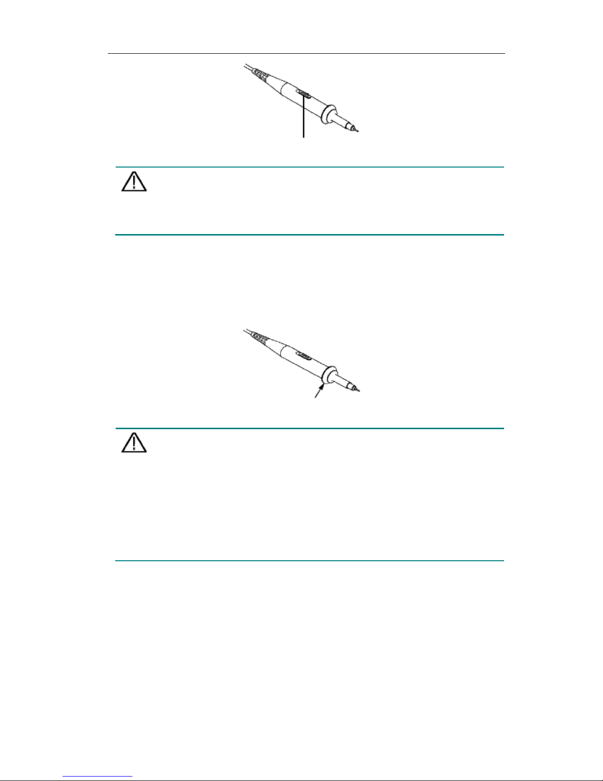
compensation is achieved (see Figure 3-8 and Figure 3-9).
Page 16
3.Quick Start
12
Overcompensated Compensated correctly Under compensated
Figure 3-8 Displayed Waveforms of the Probe Com pe nsat ion
3. Repeat the steps mentioned if needed.
Figure 3-9 Adjust Probe
How to Set the Probe Attenuation Coefficient
The probe has sev eral atten uation coefficient s, which wil l influence th e verti cal scale
factor of the oscilloscope.
To change or check the probe attenuation coefficient in the menu of oscilloscope:
(1) Press the function menu button of the used channels (CH1 MENU or CH2
MENU).
(2) Press H3 button to display the Probe menu; select the proper value corresponding
to the probe.
This setting will be valid all the time before it is changed again.
Caution:
The default attenuation coefficient of the probe on the instrument is preset to
10X.
Make sure that the set value of the attenuation switch in the probe is the
same as the menu selection of the probe attenuation coefficient
in the
oscilloscope.
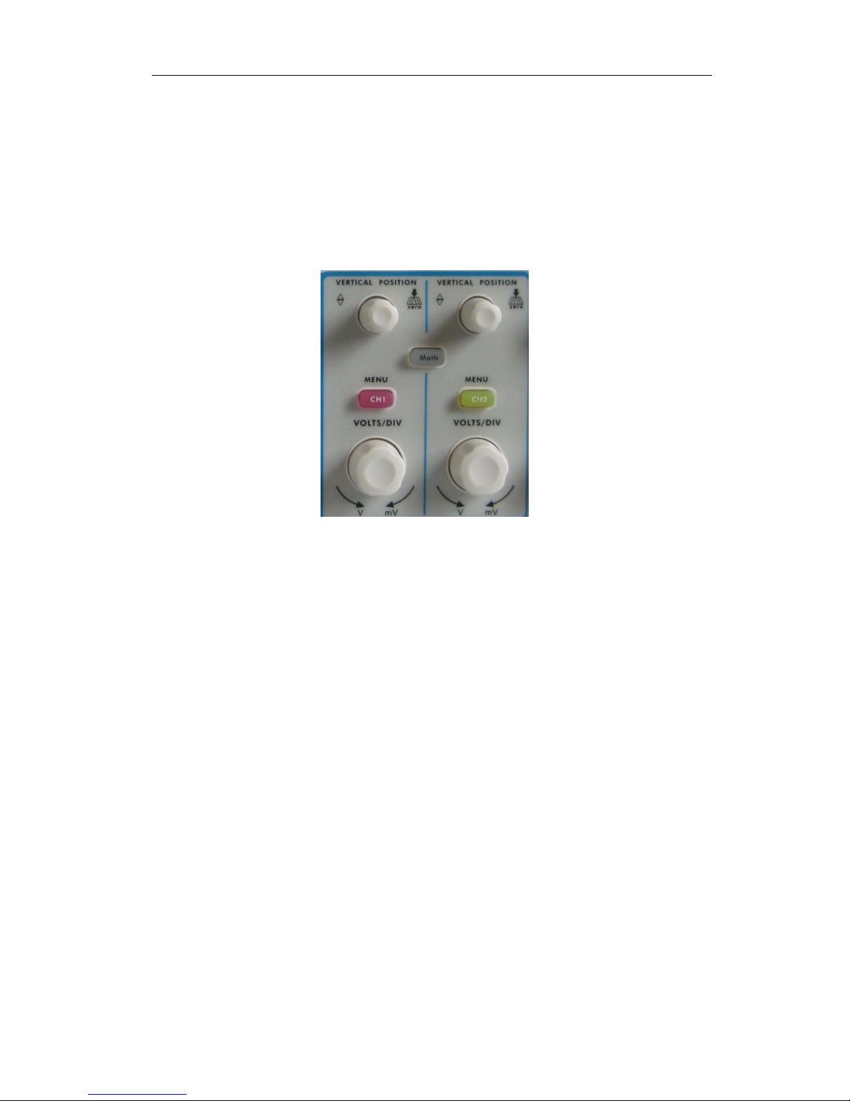
The set values of the probe switch are 1X and 10X (see Figure 3-10).
Test Equipment Depot - 800.517.8431 - 99 Washington Street Melrose, MA 02176
TestEquipmentDepot.com
Page 17
3.Quick Start
13
Figure 3-10 Attenuation Switch
Caution:
When the attenuation switch is set to 1X, the probe will limit the bandwidth
of the oscilloscope in 5MHz. To use the full bandwidth of the oscilloscope,
the switch must be set to 10X.
How to Use the Probe Safely
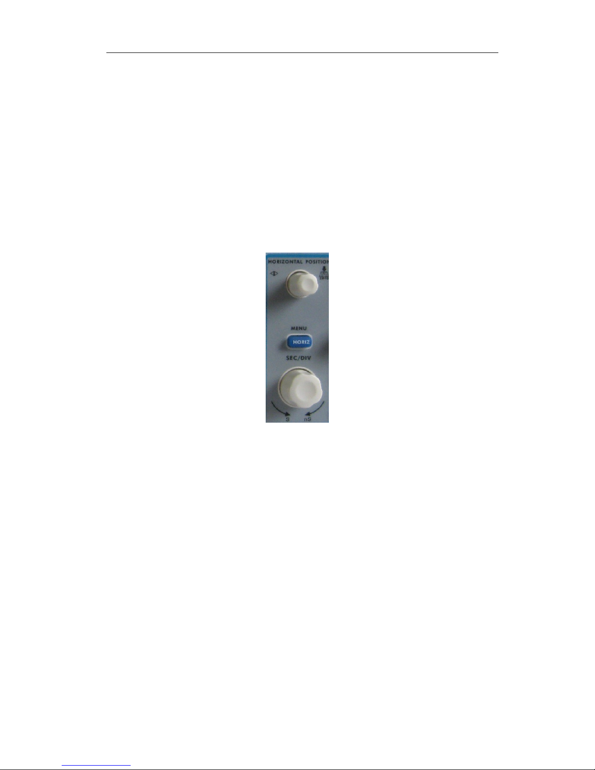
The safety guard ring around the probe body protects your finger against any electric
shock, shown as Figure 3-11.
Figure 3-11 Finger Guard
Warning:
To avoid electric shock, always keep your finger behind the safety guard
ring of the probe during the operation.
To protect you from suffering from the electric shock, do not touch any
metal part of the probe tip when it is connected to the power supply.
Before making any measurements, always
connect the probe to the
instrument and connect the ground terminal to the earth.
How to Implement Self-calibration
The self-calibration application can make the oscilloscope reach the optimum
condition rapidly to obtain the most accurate measurement value. You can carry out
this application program at any time. This program must be executed whenever the
change of ambient temperature is 5 ℃ or over.
Before performing a self-calibration, disconnect all probes or wires from the input
connector. Press the "Utility" button, then, press H1 button to call out the Function
Page 18
3.Quick Start
14
menu; turn the M knob to choose Adjust. Press H2 button to choose the option "Self
Cal"; run the program after everything is ready.
Introduction to the Vertical System
As shown in Figure 3-12, there are a few of buttons and knobs in VERTICAL
CONTROLS. The following practices will gradually direct you to be familiar with
the using of the vertical setting.
Figure 3-12 Vertical Control Zone
1. Use the button "VERTICAL POSITION" knob to show the signal in th e center of
the waveform window. The "VERTICAL POSITION" knob functions the regulating
of the vertical display position of the signal. Thus, when the "VERTICAL
POSITION" knob is rotated, the point er of the earth datum point of the channel is
directed to move up and down following the waveform.
Measuring Skill
If the channel is under the DC coupling mode, you can rapidly measure the DC
component of the signal through the observation of the difference between the wave
form and the signal ground.
If the channel is under the AC mode, the DC component would be filtered out. This
mode helps you display the AC component of the signal with a higher sensitivity.
Vertical offset back to 0 shortcut key
Turn the VERTICAL POSITION knob to change the vertical display position of
channel and press the position knob to set the vertical display position back to 0 as a
shortcut key, this is especially helpful when the trace position is far out of the screen
and want it to get back to the screen center immediately.
2. Change the Vertical Setting and Observe the Consequent State Information Change.
With the information displayed in the status bar at the bottom of the waveform
window, you can determine any changes in the channel vertical scale factor.
Page 19
3.Quick Start
15
Turn the vertical "VOLTS/DIV" knob and change the "Vertical Scale Factor
(Voltage Division)", it can be found that the scale factor of the channel
corresponding to the status bar has been changed accordingly.
Press buttons of "CH 1 MENU", "CH2 MENU " and "Math", the operation menu,
symbols, waveforms and scale factor status information of the corresponding
channel will be displayed in the screen.
Introduction to the Horizontal System
Shown as Figure 3-13, there are a button and two knobs in the "HORIZONTAL
CONTROLS". The following practices will gradually direct you to be familiar with
the setting of horizontal time base.
Figure 3-13 Horizontal C ontr ol Zone
1. Use the horizontal "SEC/DIV" knob to change the horizontal time base setting
and observe the consequent status information change. Rotate the horizontal
"SEC/DIV" knob to change the horizontal time base, and it can be found that the
"Horizontal Time Base" display in the status bar changes accordingly.
2. Use t he "HORIZONTAL POSITION" knob to adjust the horizontal position of
the signal in the waveform window. The "HORIZONTAL POSITION" knob is
used to control the triggering displacement of the signal or for other special
applications. If it is applied to triggering the displacement, it can be observed that
the waveform moves horizontally with the knob when you rotate the
"HORIZONTAL POSITION" knob.
Triggering displacement back to 0 shortcut key
Turn the HORIZONTAL POSITION knob to change the horizontal posi tion of
channel and press the HORIZONTAL POSITION knob to set the triggering
d
isplacement
back to 0 as a shortcut key.
3. With the "HORIZ MENU" button, you can do the Window Setting and the
Window Expansion.
Test Equipment Depot - 800.517.8431 - 99 Washington Street Melrose, MA 02176
TestEquipmentDepot.com
Page 20
3.Quick Start
16
Introduction to the Trigger System
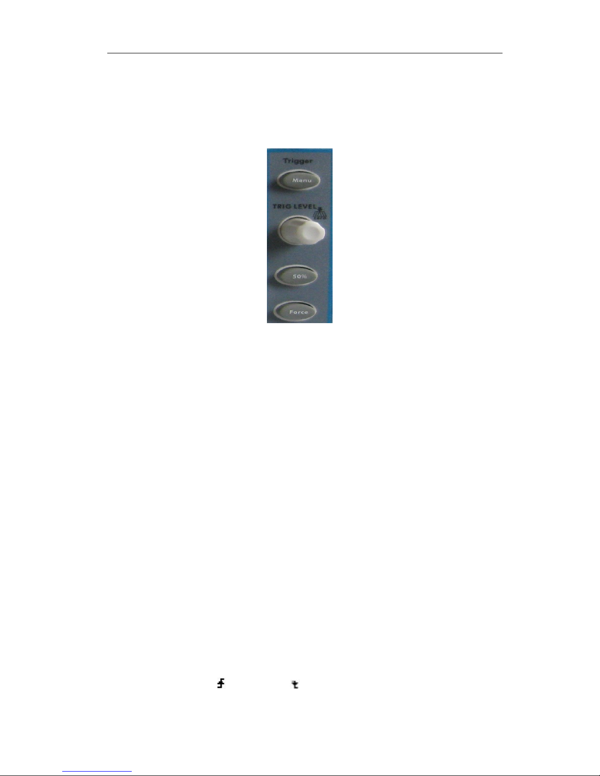
As shown in Figure 3-14, there are one knob and three buttons make up "TRIGGER
CONTROLS". The following practices will direct you to be familiar with the setting
of the trigger system gradually.
Figure 3-14 Trigger Control Zone
1. Press the "Trigger Menu" button and call out the trigger menu. With the
operations of the menu selection buttons, the trigger setting can be changed.
2. Use the "TRIG LEVEL" knob to change the trigger level setting.
By rotating the "TRIG LEVEL" knob, the trigger indicator in the screen will
move up and down. With the movement of the trigger indicator, it can be
observed that the trigger level value displayed in the screen changes accordingly.
PS: Turning the TRIG LEVEL knob can change trigger level value and it is also
the hotkey to set trigger level back to 0.
3. Press the button "50%" to set the trigger level as the vertical mid point values of
the amplitude of the trigger signal.
4. Pres s the "Force" button to force a trigger signal, which is mainly applied to the
"Normal" and "Single" trigger modes.
How to Measure Automatically
Press the Measure button to display the menu for the settings of the Automatic
Measurements. At most 8 types of measurements could be displa yed on the bottom left
of the screen.
The oscilloscopes provide 24 parameters fo r auto measurement, including Vpp, Vmax,
Vmin, Vtop, Vbase, Vamp, Vavg, Vrms, Overshoot, Preshoot, Freq, Period, Rise Time,
Fall Time, Delay A→B , Delay A→B ,+Width, -Width, +Duty, -Duty, Cycle rms,
Cursor rms, Duty cycle, and Phase.
Page 21

3.Quick Start
17
The measured values can be detected on each channel simultaneously. Only if the
waveform channel is i n t he ON st ate, the measurement can be performed. The automatic
measurement cannot be performed in the following situation: 1) On the saved waveform.
2) On the mathematical waveform. 3) On the XY format. 4) On the Scan format.
E.g. Measure the fr equ ency, the peak-to-peak voltage of the Ch annel CH1 and the mean,
the RMS of the Channel CH2, following below steps:
1. Press the Measure button to show the automatic measurement function menu.
2. Press the H1 button to display the Add menu.
3. Press the F2 button and choose CH1 as the source.
4. Press the F1 button, t he type items will display at the left of screen, and turn the M
knob to choose Period.
5. Press the F4 button, the period options added completes.
6. Press the F1 button a gain, the t ype items will display at the left of screen, and turn the
M to choose Freq.
7. Press the F4 button, the frequency added completes, finish setting of CH1.
8. Press the F2 button and choose CH2 as the source.
9. Press the F1 button, the type items will display at the left of screen, and turn the M to
choose Mean.
10. Press the F4 button, the Mean added comp let es.
11. Press the F1 button, the type items will display at the left of screen, and turn the M to
choose PK-PK.
12. Press the F4 button, the PK-PK added completes, finish setting of CH2.
The measured value will be displayed at the bottom left of the screen automatically.
How to Use Autoscale
This is a very useful function for first time users to carry out a simple and quick test on the
input signal. The function is applied to follow-up signals automatically even if the signals
change at any time. Autoscale enables the instrument to set up trigger mode, voltage
division and time scale automatically according to the type, amplitude and frequency of
the signals.
E.g. If you want to measure the two-channel signal, you can do as the follows:
1. Press Autoscale button, the function menu will appear.
2. Press H1 to choose ON.
3. Press H2 and choose for Mode item.
4. Press H3 and choose for Wave item.
Page 22
4.Communication with PC
18
4. Communication with PC
SDS series digital storage oscilloscope support communications with a PC through USB,
LAN or COM port. You can use the Oscilloscope communication software to store,
analyze, display the data and remote control.
Here is how to connect with PC. First, install the Oscilloscope communication software on
the supplied CD. Then there are several ways of connection to choose from.
Using USB Port
(1) Connection: Use a USB data cable to connect the US B Devi ce p or t in the right panel
of the Oscilloscope to the USB port of a PC.
(2) Ins tall the dri ver: Run the Oscilloscope communication software on PC, press F1 to
open the help document. Follow the steps of title "I. Device connection" in the
document to install the driver.
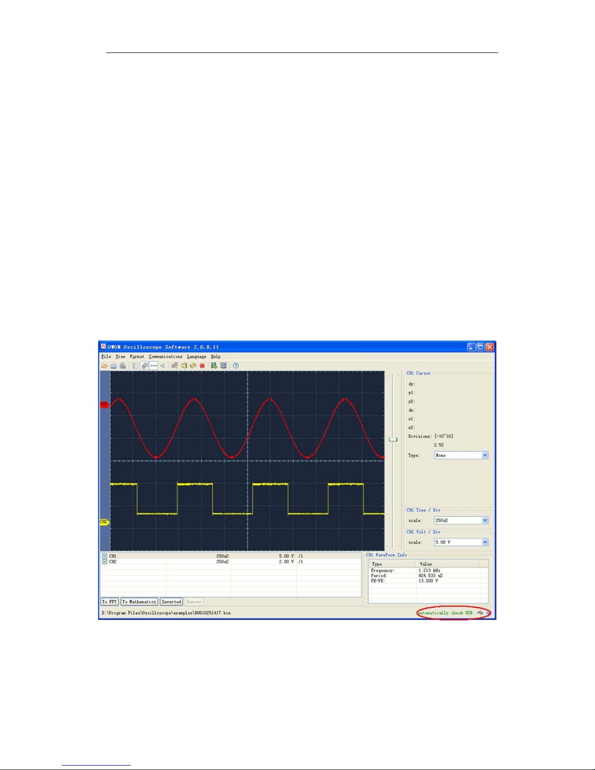
(3) Port setting of the software: Run the Oscilloscope software; click
"Communications" in the menu bar, choose "Ports-Settings", in the setting dialog,
choose "Connect using" as "USB". After connect successfully, the connection
information in the bottom right corner of the software will turn green.
Figure 4-1: Connect with PC through USB port
Test Equipment Depot - 800.517.8431 - 99 Washington Street Melrose, MA 02176
TestEquipmentDepot.com
Page 23
4.Communication with PC
19
Using LAN Port
Connect directly
(1) Connection. Plug in the LAN line to the LAN port in the right side panel of the
oscilloscope; plug the other end into the LAN interface of the computer.
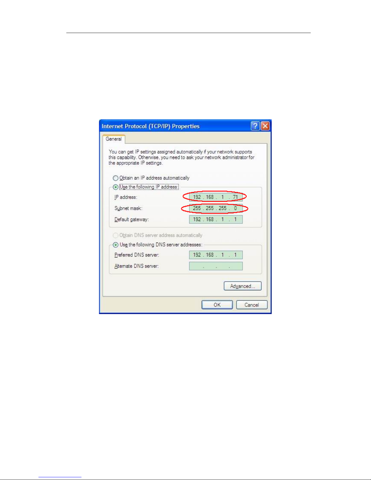
(2) Set the network parameters of the computer. Since the oscilloscope can not
support obtaining an IP address automatically, you should assign a static IP address.
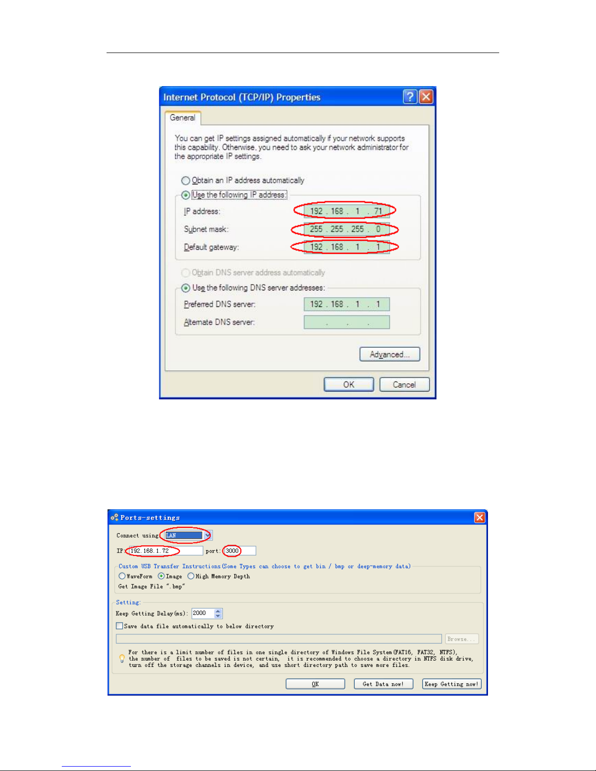
Here we set the IP address to 192.168.1.71.
Figure 4-2 Set the network parameters of the computer
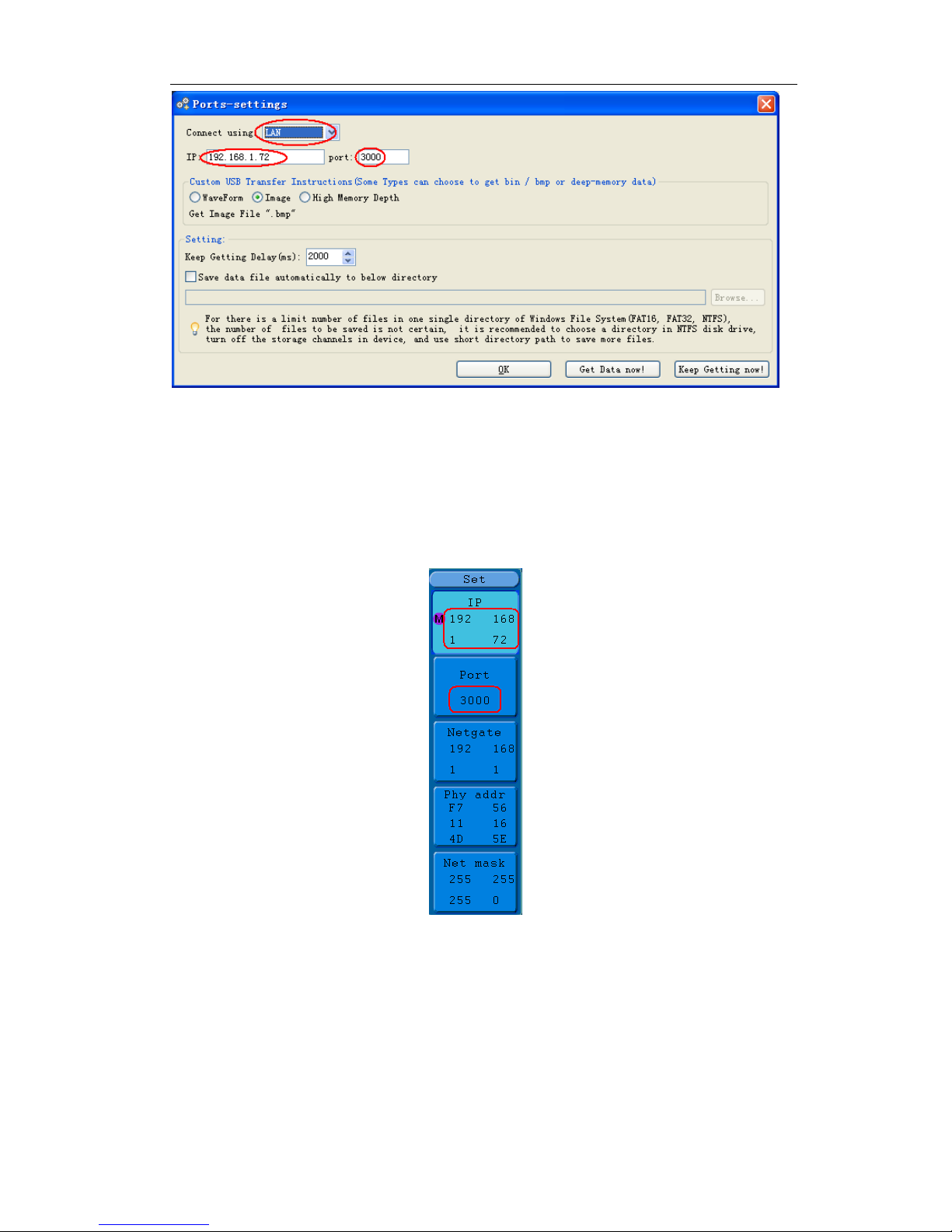
(3) Set the network parameters of the OWON Oscilloscope Software. Run the
software on the computer; choose the "Ports-settings" of the "Communications" menu
item. Set "Connect using" to LAN. About the IP, the first three bytes is same as the IP
in the step (2), the last byte should be different. Here, we set it to 192.168.1.72. The
range of the port value is 0 - 4000, but the port which under 2000 is always be used,
so it is suggested to set it to the value above 2000. Here, we set it to 3000.
Page 24
4.Communication with PC
20
Figure 4-3 Set the network parameters of the OWON Oscilloscope Software
(4) Set the network parameters of the oscilloscope. In the oscilloscope, press the
Utility button and press H1 button, turn the M knob to select the LAN Set; press the
H2 button, the set menu is displayed on the right. Set the IP and the Port to the same
value as the "Ports-settings" in the software in step (3). Press the H3 button t o select
"Save set", it prompts "reset to update the config". After resetting the oscilloscope, if
you can get data normally in the oscilloscope software, the connection is successful.
Figure 4-4 Set the network parameters of the oscilloscope
Connect through a router
(1) Connection. Use a LAN line to connect the oscillos cope with a router, the LAN port
of the oscilloscope is in the right side panel; the computer should be connected to the
router too.
(2) Set the network parameters of the computer. Since the oscilloscope can not
support obtaining an IP address automatically, you should assign a static IP address.
The Default gateway and Subnet mask should be set according to the router. Here we
Test Equipment Depot - 800.517.8431 - 99 Washington Street Melrose, MA 02176
TestEquipmentDepot.com
Page 25
4.Communication with PC
21
set the IP address to 192.168.1.71, Subnet mask is 255.255.255.0, Default gateway is
192.168.1.1.
Figure 4-5 Set the network parameters of the computer
(3) Set the network parameters of the OWON Oscilloscope Software. Run the
software on the computer; choose the "Ports-settings" of the "Communications" menu
item. Set "Connect using" to LAN. About the IP, the first three bytes is same as the IP
in the step (2), the last byte should be different. Here, we set it to 192.168.1.72. The
range of the port value is 0 - 4000, but the port which under 2000 is always be used,
so it is suggested to set it to the value above 2000. Here, we set it to 3000.
Figure 4-6 Set the network parameters of the OWON Oscilloscope Software
Page 26
4.Communication with PC
22
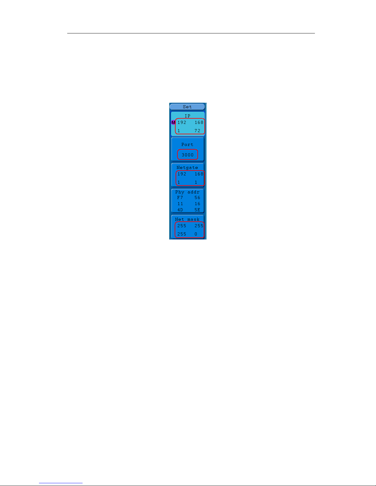
(4) Set the network parameters of the oscilloscope. In the oscilloscope, press the
Utility button and press H1 button, turn the M knob to select the LAN Set; press the
H2 button, the set menu is displayed on the right. Set the IP and the Port to the same
value as the "Ports-settings" in the softw are in step (3). The Netgate and Net mask
should be set according to the router. Press the H3 button to select "Save set", it
prompts "reset to update the config". After resetting the oscilloscope, if you can get
data normally in the oscilloscope software, the connection is successful.
Figure 4-7 Set the network parameters of the oscilloscope
Using COM Port
(1) Connection. Use a data cable to connect the COM port in the right panel of the
Oscilloscope, to the COM port of a PC.
(2) Port setting of the software: Run the Oscilloscope software; click
"Communications" in the menu bar, choose "Ports-Settings", in the setting dialog,
choose "Connect using" as COM.
To learn about how to operate the software, you can press F1 in the software to open the
help document.
Page 27
5.Performance parameters
23
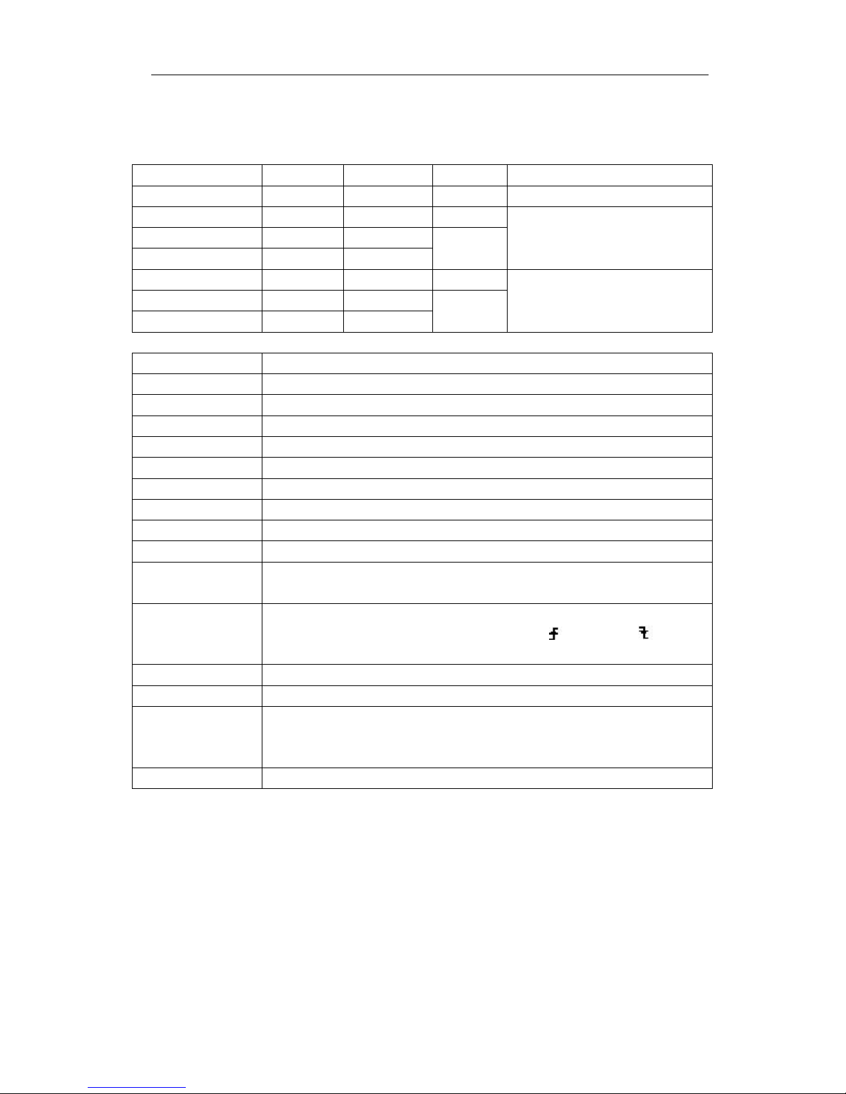
5. Performance parameters
Note: "V" for VGA interface (optional), SDS8302 and SDS9302 including VGA interface as default.
Model
Bandwidth
Sample rate
Rise time
Horizontal Scale(S/div)
SDS6062(V)
60 MHz 500 MS/s ≤ 5.8 ns 5 ns/div – 100 s/div, step by1-2-5
SDS7072(V)
70 MHz 1 GS/s ≤ 5.0 ns
2 ns/div – 100 s/div, step by1-2-5
SDS7102(V)
100 MHz 1 GS/s
≤ 3.5 ns
SDS8102(V)
100 MHz 2 GS/s
SDS8202(V)
200 MHz 2 GS/s ≤ 1.7 ns
1 ns/div – 100 s/div, step by1-2-5
SDS8302
300 MHz 2.5 GS/s
≤ 1.17 ns
SDS9302
300 MHz 3.2 GS/s
Display
8" Colored LCD, 800 x 600 pixels, 65536 colors
Channel
2 + 1 (External)
Record length
Max 10M
Input coupling
DC, AC , Ground
Input impedance
1 MΩ ± 2%, in parallel with 10 pF ± 5 pF
Max. input voltage
400 V (PK-PK) (DC + AC PK-PK)
DC gain accuracy
± 3%
Vertical sensitivity
2 mV/div - 10 V/div
Trigger type
Edge, Video, Slope, Pulse, Alternat e
Trigger mode
Auto, Normal, Single
Line/field
frequency (Video)
Support standard NTSC, PAL and SECAM broadcast systems
Automatic
measurement
Vpp, Vmax, Vmin, Vtop, Vbas e, Vamp, Vavg, Vrms, Overshoot, Pr eshoot,
Freq, Period, Rise Time, Fall Time, Delay A→B
, Delay A→B , +W idth,
-Width, +Duty, -Duty, Cycle rms, Cursor rms, Duty cycle, Phase
Waveform Math
+, -, ×, ÷, FFT
Waveform storage
15 waveforms
Communication
interface
USB 2.0, USB flash disk storage; LAN, Pass/Fail; VGA interface (only for the
model with "V" or the m odels includ ing VGA inter face as default) or R S-232
(Optional);
Power supply
100 V – 240 V AC, 50/60 HZ,CAT Ⅱ
Test Equipment Depot - 800.517.8431 - 99 Washington Street Melrose, MA 02176
TestEquipmentDepot.com
Page 28
6.Appendix
24
6. Appendix
Appendix A: Enclosure
Standard Accessories:
A pair of Passive probe: 1.2 m, 1:1 (10:1)
1x CD (PC link application software)
1x Power cord: up to the standards of the country in which it is used.
1x USB cable
1x Quick Guide
Options:
Battery
Appendix B: General Care and Cleaning
General Care
Do not store or leave the instrument where the liquid crystal display will be exposed
to direct sunlight for long periods of time.
Caution: To avoid any damage to the instrument or probe, do not exposed it to any
sprays, liquids, or solvents.
Cleaning
Inspect the instrument and probes as often as operating conditions require.
To clean the instrument exterior, perform the following steps:
1. Wipe the dust from the instrument and probe surface with a soft cloth. Do not
make any scuffin g on the transparent LCD pro te ct i on s cre en w h en cl ean t he LCD
screen.
2. Disconnect power before cleaning your Oscilloscope. Clean the instrument with a
wet soft cloth not dripping water. It is recommended to scrub with soft detergent
or fresh water. To avoid damage to the instrument or probe, do not use any
corrosive chemical cleaning agent.
Warning:
Before power on again for operation, it is required to confirm that
the instrument has already been dried completely, avoiding any
electrical short circuit or bodily injury resulting form the moisture.
Appendix C: USB Disk Requirements
The supported format of the USB disk: FAT32 file system, allocation unit siz e cannot
exceed 4K, mass stor age USB disk is also supported. If the US B disk doesn't work
properly, format it into the supported format and try again. About the methods to
format the USB disk, refer to SDS Series Smart Digital Storage Oscilloscopes User
Manual.
 Loading...