

Page 1

HDS200 Dual Channel Series
Handheld Oscilloscope User Manual
◼ HDS272
(S)
◼ HDS242(S)
For product support, visit:www.owon.com.hk/download
Page 2

Apr 2021 edition V1.0.1
Copyright © LILLIPUT Company. All rights reserved.
The LILLIPUT's products are under the protection of the patent rights, including ones
which have already obtained the patent rights and those which are applied for. The
information in this manual will replace all materials published.
The information in this manual was correct at the time of printing. However, LILLIPUT will
continue to improve products and reserves the rights to change specification at any time
without notice.
is the registered trademark of the LILLIPUT Company.
Fujian LILLIPUT Optoelectronics Technology Co., Ltd.
No. 19, Heming Road
Lantian Industrial Zone, Zhangzhou 363005 P.R. China
Page 3

General Warranty
We warrants that the product will be free from defects in materials and
workmanship for a period of 3 years from the date of purchase of the product
by the original purchaser from the our Company. The warranty period for
accessories such as probes, adapter is 12 months. This warranty only applies
to the original purchaser and is not transferable to a third party.
If the product proves defective during the warranty period, we will either repair
the defective product without charge for parts and labour, or will provide a
replacement in exchange for the defective product. Parts, modules and
replacement products used by our company for warranty work may be new or
reconditioned like new. All replaced parts, modules and products become the
property of our company.
In order to obtain service under this warranty, the customer must notify our
company of the defect before the expiration of the warranty period. Customer
shall be responsible for packaging and shipping the defective product to the
designated service centre, a copy of the customers proof of purchase is also
required.
This warranty shall not apply to any defect, failure or damage caused by
improper use or improper or inadequate maintenance and care. We shall not
be obligated to furnish service under this warranty a) to repair damage
resulting from attempts by personnel other than our company representatives
to install, repair or service the product; b) to repair damage resulting from
improper use or connection to incompatible equipment; c) to repair any
damage or malfunction caused by the use of not our supplies; or d) to service a
product that has been modified or integrated with other products when the
effect of such modification or integration increases the time or difficulty of
servicing the product.
Please contact the nearest Sales and Service Offices for services or a
complete copy of the warranty statement.
Excepting the after-sales services provided in this summary or the
applicable warranty statements, we will not offer any guarantee for
maintenance definitely declared or hinted, including but not limited to
the implied guarantee for marketability and special-purpose acceptability.
We should not take any responsibilities for any indirect, special or
consequent damages
Page 4

i
1. PRODUCT CERTIFICATE · · · · · · · · · · · · · · · · · · · · · · · · · · · · · · · · · 1
2. SAFETY INFORMATION · · · · · · · · · · · · · · · · · · · · · · · · · · · · · · · · · · · 2
3. HOW TO IMPLEMENT THE GENERAL INSPECTION
5
4. HOW TO USE THE OSCILLOSCOPE · · · · · · · · · · · · · · · · · · 6
The Structure of the Oscilloscope · · · · · · · · · · · · · · · · · · · · · · · · · · · · · · · · · · · · · · · · · · · · · · · · · · · · · · · · · · · · · · · · · · · · · · · · · 6
Front Panel and Keys · · · · · · · · · · · · · · · · · · · · · · · · · · · · · · · · · · · · · · · · · · · · · · · · · · · · · · · · · · · · · · · · · · · · · · · · · · · · · · · · · · · · · · · · · 6
Side Panel · · · · · · · · · · · · · · · · · · · · · · · · · · · · · · · · · · · · · · · · · · · · · · · · · · · · · · · · · · · · · · · · · · · · · · · · · · · · · · · · · · · · · · · · · · · · · · · · · · · · · · · 8
Introduction to the User Interface of the Oscilloscope · · · · · · · · · · · · · · · · · · · · · · · · · · · · · · · · · · · · · · · · · · · · · · · · 9
Functional Check · · · · · · · · · · · · · · · · · · · · · · · · · · · · · · · · · · · · · · · · · · · · · · · · · · · · · · · · · · · · · · · · · · · · · · · · · · · · · · · · · · · · · · · · · · · · 10
Probe Compensation · · · · · · · · · · · · · · · · · · · · · · · · · · · · · · · · · · · · · · · · · · · · · · · · · · · · · · · · · · · · · · · · · · · · · · · · · · · · · · · · · · · · · · · 11
Probe Attenuation Coefficient Setting · · · · · · · · · · · · · · · · · · · · · · · · · · · · · · · · · · · · · · · · · · · · · · · · · · · · · · · · · · · · · · · · · · · 12
Safe Use of Probe · · · · · · · · · · · · · · · · · · · · · · · · · · · · · · · · · · · · · · · · · · · · · · · · · · · · · · · · · · · · · · · · · · · · · · · · · · · · · · · · · · · · · · · · · · · 13
Vertical System · · · · · · · · · · · · · · · · · · · · · · · · · · · · · · · · · · · · · · · · · · · · · · · · · · · · · · · · · · · · · · · · · · · · · · · · · · · · · · · · · · · · · · · · · · · · · · · 14
Horizontal System · · · · · · · · · · · · · · · · · · · · · · · · · · · · · · · · · · · · · · · · · · · · · · · · · · · · · · · · · · · · · · · · · · · · · · · · · · · · · · · · · · · · · · · · · · · 15
Measuring System · · · · · · · · · · · · · · · · · · · · · · · · · · · · · · · · · · · · · · · · · · · · · · · · · · · · · · · · · · · · · · · · · · · · · · · · · · · · · · · · · · · · · · · · · · · 16
5. HOW TO USE THE MULTIMETER · · · · · · · · · · · · · · · · · · · · · 22
About This Chapter · · · · · · · · · · · · · · · · · · · · · · · · · · · · · · · · · · · · · · · · · · · · · · · · · · · · · · · · · · · · · · · · · · · · · · · · · · · · · · · · · · · · · · · · · · 22
Instrument Interface · · · · · · · · · · · · · · · · · · · · · · · · · · · · · · · · · · · · · · · · · · · · · · · · · · · · · · · · · · · · · · · · · · · · · · · · · · · · · · · · · · · · · · · · · 22
6. HOW TO USE THE WAVEFORM GENERATOR
(OPTIONAL) · · · · · · · · · · · · · · · · · · · · · · · · · · · · · · · · · · · · · · · · · · · · · · · · · · · · 25
Connect the output · · · · · · · · · · · · · · · · · · · · · · · · · · · · · · · · · · · · · · · · · · · · · · · · · · · · · · · · · · · · · · · · · · · · · · · · · · · · · · · · · · · · · · · · · · · 25
Set the waveform · · · · · · · · · · · · · · · · · · · · · · · · · · · · · · · · · · · · · · · · · · · · · · · · · · · · · · · · · · · · · · · · · · · · · · · · · · · · · · · · · · · · · · · · · · · · · · 25
Set the load · · · · · · · · · · · · · · · · · · · · · · · · · · · · · · · · · · · · · · · · · · · · · · · · · · · · · · · · · · · · · · · · · · · · · · · · · · · · · · · · · · · · · · · · · · · · · · · · · · · 25
Output the sine waveform · · · · · · · · · · · · · · · · · · · · · · · · · · · · · · · · · · · · · · · · · · · · · · · · · · · · · · · · · · · · · · · · · · · · · · · · · · · · · · · · · 26
Output the square waveform · · · · · · · · · · · · · · · · · · · · · · · · · · · · · · · · · · · · · · · · · · · · · · · · · · · · · · · · · · · · · · · · · · · · · · · · · · · · · · 27
Output the ramp waveform · · · · · · · · · · · · · · · · · · · · · · · · · · · · · · · · · · · · · · · · · · · · · · · · · · · · · · · · · · · · · · · · · · · · · · · · · · · · · · · · 27
Output the pulse waveform · · · · · · · · · · · · · · · · · · · · · · · · · · · · · · · · · · · · · · · · · · · · · · · · · · · · · · · · · · · · · · · · · · · · · · · · · · · · · · · · 27
Output the Arbitrary waveform · · · · · · · · · · · · · · · · · · · · · · · · · · · · · · · · · · · · · · · · · · · · · · · · · · · · · · · · · · · · · · · · · · · · · · · · · · · · 28
7. COMMUNICATION WITH PC · · · · · · · · · · · · · · · · · · · · · · · · · · · · 29
8. TROUBLESHOOTING · · · · · · · · · · · · · · · · · · · · · · · · · · · · · · · · · · · · · 30
9. TECHNICAL SPECIFICATIONS · · · · · · · · · · · · · · · · · · · · · · · · 32
Page 5

ii
Oscilloscope · · · · · · · · · · · · · · · · · · · · · · · · · · · · · · · · · · · · · · · · · · · · · · · · · · · · · · · · · · · · · · · · · · · · · · · · · · · · · · · · · · · · · · · · · · · · · · · · · · 32
Multimeter · · · · · · · · · · · · · · · · · · · · · · · · · · · · · · · · · · · · · · · · · · · · · · · · · · · · · · · · · · · · · · · · · · · · · · · · · · · · · · · · · · · · · · · · · · · · · · · · · · · · · 34
Arbitrary Waveform Generator ( (Optional) · · · · · · · · · · · · · · · · · · · · · · · · · · · · · · · · · · · · · · · · · · · · · · · · · · · · · · · · · 35
General Technical Specifications · · · · · · · · · · · · · · · · · · · · · · · · · · · · · · · · · · · · · · · · · · · · · · · · · · · · · · · · · · · · · · · · · · · · · · · · 36
10. APPENDIX · · · · · · · · · · · · · · · · · · · · · · · · · · · · · · · · · · · · · · · · · · · · · · · · · · 37
Appendix A: List of Accessories · · · · · · · · · · · · · · · · · · · · · · · · · · · · · · · · · · · · · · · · · · · · · · · · · · · · · · · · · · · · · · · · · · · · · · · · · · 37
Appendix B: Maintenance and Cleaning · · · · · · · · · · · · · · · · · · · · · · · · · · · · · · · · · · · · · · · · · · · · · · · · · · · · · · · · · · · · · · · 37
Page 6

1
1. Product Certificate
HDS200 Series Handheld Oscilloscope
Manufacturer: Fujian LILLIPUT Optoelectronic Technology Co., Ltd.
Declaration of conformity:
This product complies with the European Community regulations on
electromagnetic compatibility 2014/30/EU and low voltage 2014/35/EU
Product inspection:
Standards adopted
EN61010-1: 2010 (2nd edition)
Safety requirements for electrical equipment for measurement, control, and
laboratory use
EN61326-1: 2013
Electrical equipment for measurement, control and laboratory use – EMC
requirements
EN61000-3-2: 2014
Limits for harmonic current emissions (equipment input current≤16 A per
phase)
EN61000-3-3: 2013
Limitation of voltage fluctuations and flicker in low-voltage supply systems for
equipment with rated current≤16A
Inspection is made under normal settings
The symbol indicating conformity is CE, that is, "Conformite Europeenne".
Page 7
2
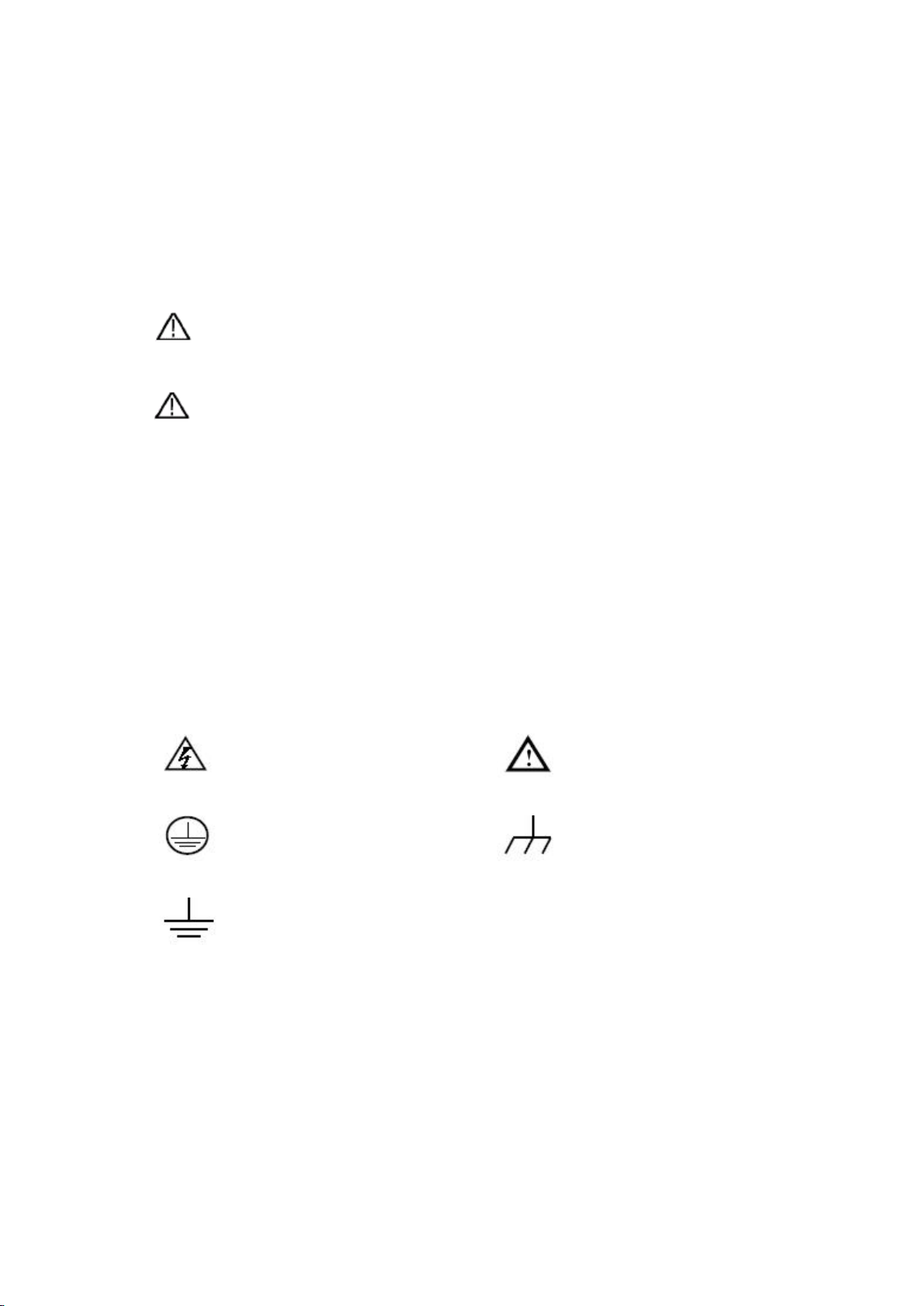
Hazardous Voltage
Refer to Manual
Protective Earth Terminal
Chassis Ground
Test Ground
2. Safety Information
(Before using this product, please read the safety information in advance)
Safety Terms
Terms in this manual (The following terms may appear in this manual):
Warning: Warning indicates conditions or practices that could result
in injury or loss of life.
Caution: Caution indicates the conditions or practices that could
result in damage to this product or other property.
Terms on the product. The following terms may appear on this product:
Danger: Indicates an immediate hazard or injury possibility.
Warning: Indicates a possible hazard or injury.
Caution: Indicates potential damage to the instrument or other property.
Safety Symbols
Symbols on the product. The following symbol may appear on the
product:
Safety Requirements
Please read the following safety precautions to avoid personal injury and
prevent damage to this product or any other products connected to it. In order
to avoid possible hazards, this product can only be used within the specified
range.
Page 8
3
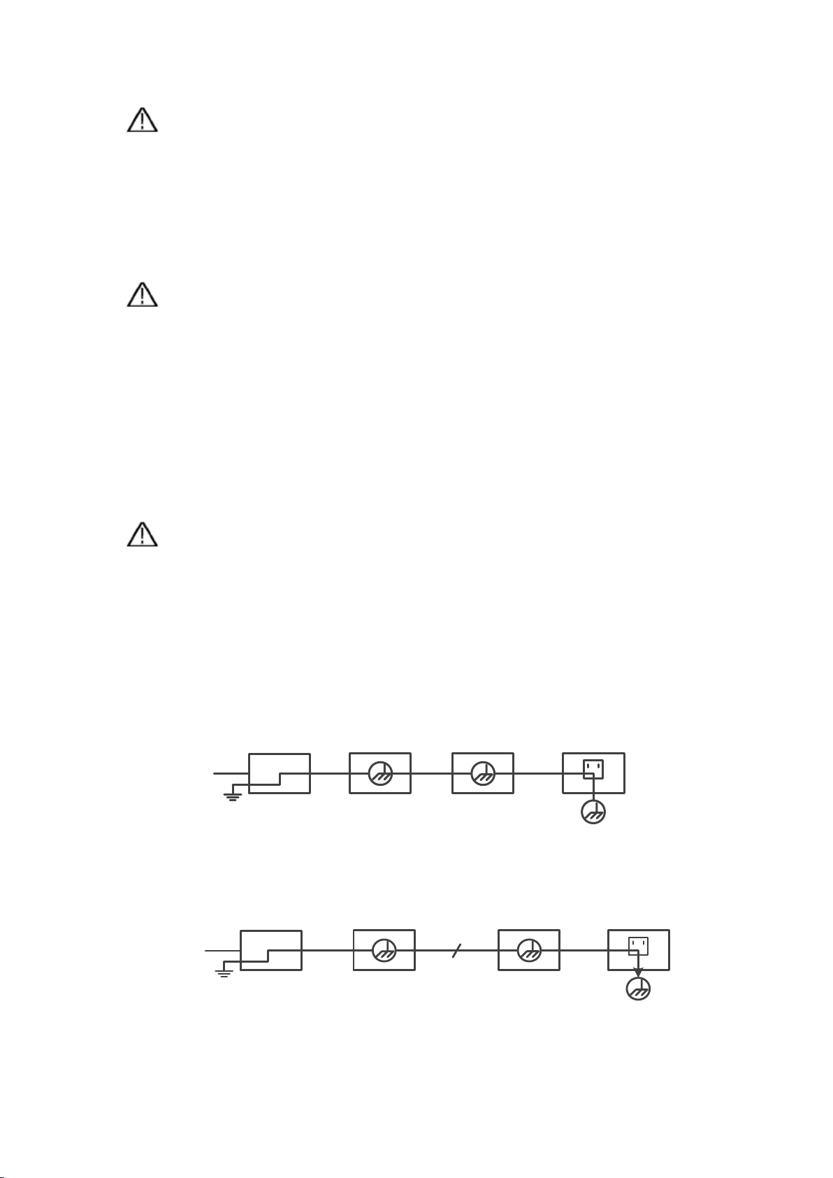
Ground Clip
Signal Input
Electrical Outlet
Probe
AC Adapter
Oscilloscope
Ground Clip
Signal Input
Oscilloscope
PC Electrical OutletProbe
USB Cable
Warning:
To prevent electric shock or fire, use a suitable power adapter. Only power
adapters that are dedicated to this product and approved for use in the country
of use may be used.
Warning:
The two channels of the oscilloscope are non-isolated channels. Note that the
channel should use a common reference when measuring, and the ground
wires of the two probes cannot be connected to two non-isolated places with
different DC electrical levels, otherwise it may cause a short circuit due to the
ground wire connection of the oscilloscope probe.
Warning:
Note that the channel should use a common reference when measuring,
otherwise it may cause a short circuit due to the ground wire connection of the
oscilloscope probe.
Schematic diagram of the internal ground wire connection of the oscilloscope:
Schematic diagram of internal ground connection when oscilloscope is
connected with computer through the port:
When the oscilloscope is AC powered by adapter or connected with AC
Page 9

4
powered computer through the port, it is not allowed to measure the primary
power supply of power grid.
Warning:
If the input port of the oscilloscope is connected to a voltage with a peak value
higher than 42V (30vrms) or a circuit with a peak value of more than 4800 VA,
the following measures shall be taken to avoid electric shock or fire:
⚫ Only voltage probes, test wires and adapters with proper insulation
attached to the oscilloscope or accessories suitable for oscilloscope
instrument series products specified by our company shall be used.
⚫ Before use, check the multimeter test probe, oscilloscope probe and
accessories for mechanical damage. If damage available, replace it.
⚫ Remove all unused multimeter test probes, oscilloscope probes and
accessories (power adapter, USB, etc.).
⚫ Firstly, plug the power adapter into the AC socket, and then connect it to
the oscilloscope.
⚫ When testing in a CAT II environment, do not connect a voltage higher
than 400 V to any input port.
⚫ When testing in a CAT II environment, do not connect a voltage with a
voltage difference of more than 400 V to the isolated input port.
⚫ Do not use an input voltage higher than the rated value of the instrument.
Pay special attention when using 1:1 test wires, because the probe voltage
will be directly transmitted to the oscilloscope.
⚫ Do not touch the bare metal BNC or banana plug.
⚫ Do not insert metal objects into the connector.
⚫ Use the oscilloscope only in the specified way.
⚫ The voltage rating mentioned in the "warning" information is the limited
value of "working voltage". They represent V ac rms (50-60 Hz) in AC sine
wave applications; and V dc in DC applications. CAT is the prefix, and II
Page 10

5
refers to the level. Level II is the low voltage and high energy level, which
refers to the local electrical level applicable to electrical appliances and
portable equipment.
◼ Only a qualified person should perform internal maintenance.
◼ Check all Terminal Ratings. To avoid fire or shock hazard, check all
ratings and markings on this product. Refer to the user manual for more
information about ratings before connecting to the instrument.
◼ Do not operate without covers. Do not operate the instrument with
covers or panels removed.
◼ Avoid exposed circuit. Be careful when working on exposed circuitry to
avoid risk of electric shock or other injury.
◼ Do not operate if any damage. If you suspect damage to the instrument,
have it inspected by qualified service personnel before further use.
◼ Do not operate in damp conditions.
◼ Do not operate in an explosive atmosphere.
◼ Keep product surfaces clean and dry.
◼ Using the equipment not in accordance with the method specified
by the manufacturer may damage the protection provided by the
equipment.
3. How to Implement the General Inspection
After you get a new oscilloscope, it is recommended that you should
make a check on the instrument according to the following steps:
1. Check whether there is any damage caused by transportation.
If it is found that the packaging carton or the foamed plastic protection
cushion has suffered serious damage, do not throw it away first till the
complete device and its accessories succeed in the electrical and
mechanical property tests.
2. Check the Accessories
The supplied accessories have been already described in the "Appendix A:
List of Accessories" of this Manual. You can check whether there is any loss
of accessories with reference to this description. If it is found that there is
any accessory lost or damaged, please get in touch with our distributor
responsible for this service or our local offices.
3. Check the Complete Instrument
If it is found that there is damage to the appearance of the instrument, or the
Page 11
6
4
11
6
7
9
10
16
15
14
13
12
517
3
8
1
2
instrument can not work normally, or fails in the performance test, please get in
touch with our distributor responsible for this business or our local offices. If
there is damage to the instrument caused by the transportation, please keep
the package. With the transportation department or our distributor responsible
for this business informed about it, a repairing or replacement of the instrument
will be arranged by us.
4. How to Use the Oscilloscope
The Structure of the Oscilloscope
Front Panel and Keys
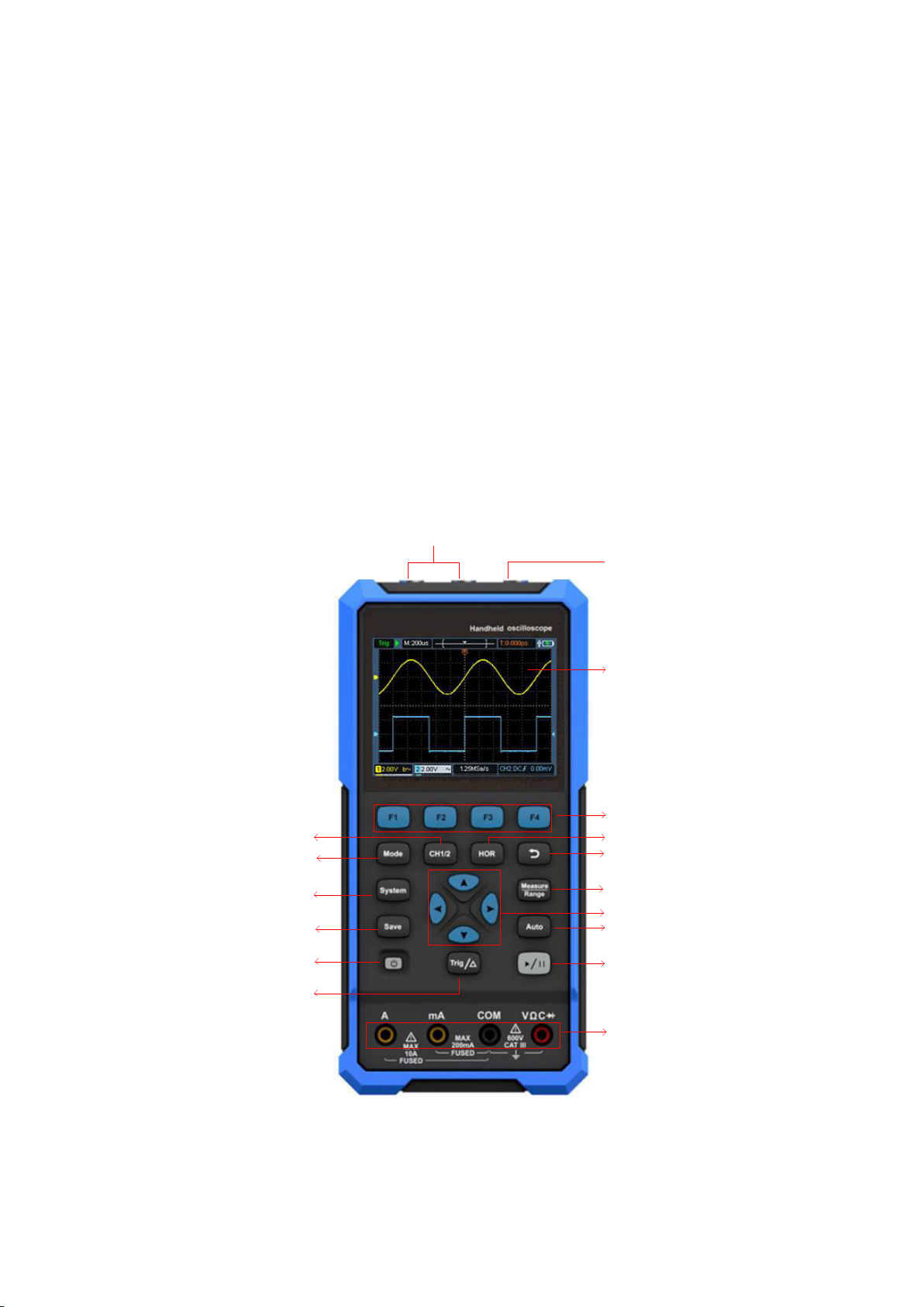
The front panel and keys of the oscilloscope are shown in Figure 4:
Description:
Figure 4: Front Panel of the Oscilloscope
Page 12
7
1. CH1 and CH2 input connectors.
2. Waveform generator output connector (optional).
3. Display area.
4. The F1 - F4 keys are multi-function keys. In each menu mode, press the
corresponding key to select the corresponding menu item.
5. After pressing the HOR key, through the key
, you can change the
horizontal time base setting, and observe the change of the state
information caused by it; it can also be found that the horizontal time
base display corresponding to the status bar has changed correspondingly;
the horizontal displacement of the signal in the waveform window can be
adjusted by pressing
.
6. Return key. Press this key to return to the previous menu; when the menu
is the first level, press the return key to close the menu.
7. Measurement menu key (oscilloscope) or range key (multimeter).
8. Zoom or move key:
Function of direction keys
: used for the up and down movements of
waveform, the time base changing, the voltage cursor movements and the
trigger of electrical level change in the oscilloscope;
Function of direction keys
: used for the left and right movements of
waveform, the voltage position changing and the movements of time
cursor in the oscilloscope.
9. Automatic setting key (oscilloscope) or automatic range key (multimeter).
10. Stop / run key (oscilloscope) or value hold key (multimeter) or turn on/off
the signal output (waveform generator - optional).
11. Input end of the multimeter.
12. Trigger menu key (oscilloscope) or relative value key (multimeter).
13.
Power switch key.
:
14. Enter the save settings key.
15. Enter the system settings key.
Page 13
8
1
2
3
16. Switch key for working state of oscilloscope and multimeter.
17. CH1 / CH2 - channel switch key.
Side Panel
Description:
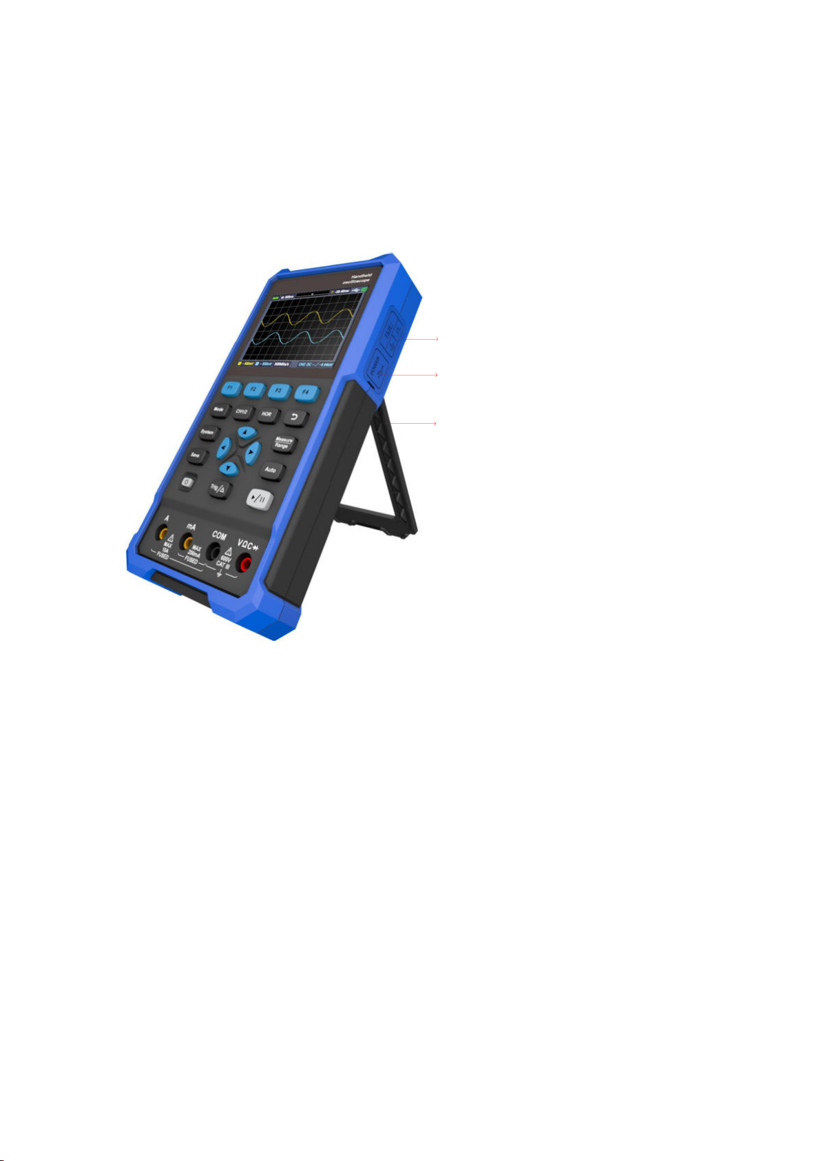
1. Probe compensation: 3.3V/1kHz square wave signal output
2. Charging or USB communication interface
3. Bracket
Page 14
9
1
2
3
4
5
6
8
9
10
11
1213
14
15
16
17
7
Introduction to the User Interface of the Oscilloscope
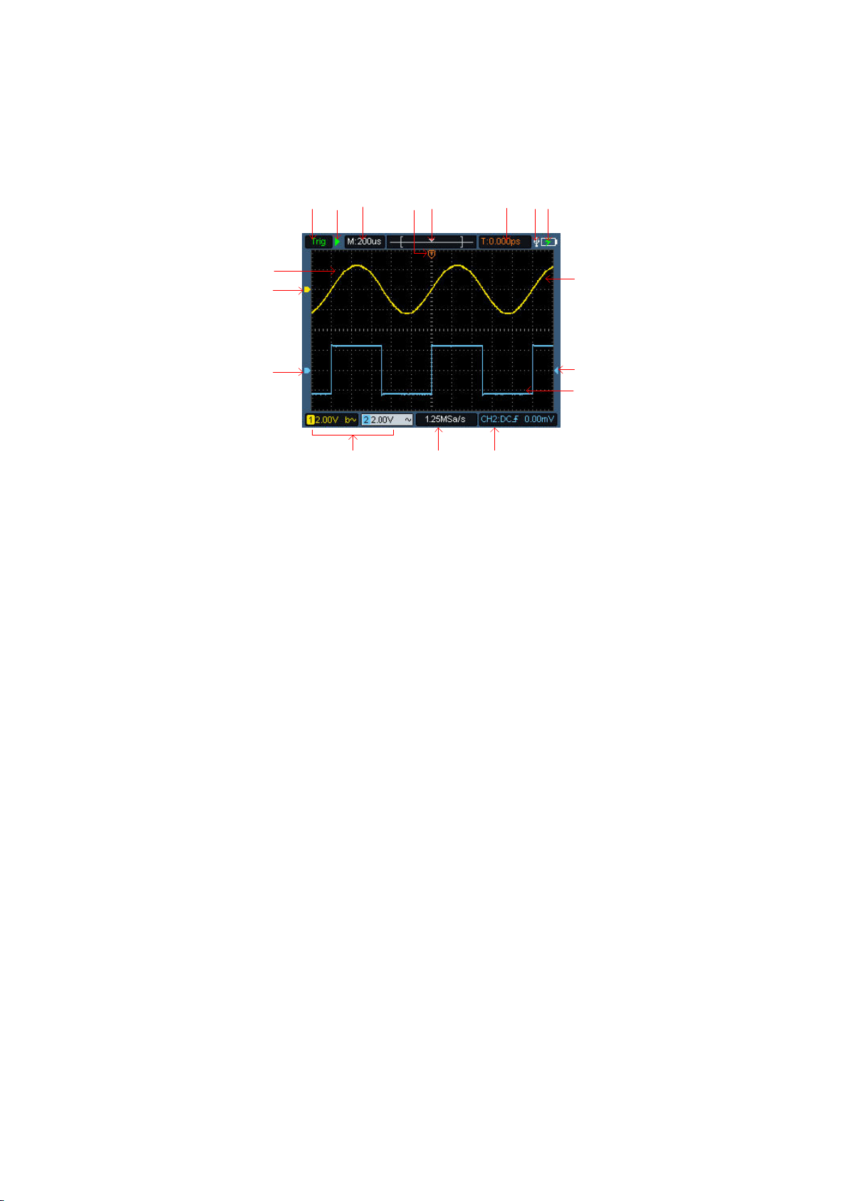
Figure 5: Oscilloscope Interface
Description:
1. The trigger status indicates the following information:
Auto: Automatic mode. The waveform is being collected without triggering.
Trig: A trigger has been detected and post trigger information is being
collected.
Ready: All pre trigger data have been obtained and the oscilloscope is
ready.
Scan: Scan mode. Continuously collect and display waveform data.
Stop: Stop collecting waveform data.
2. Run/stop.
3. Time base display.
4. The pointer indicates the trigger horizontal position.
5. The pointer indicates the trigger position within the current storage depth.
6. Indicating the value of the current trigger horizontal displacement, and
displaying the position of the current waveform window in the memory.
7. Battery power and external power supply indication.
8. Channel 1 waveform.
9. The pointer indicates the trigger electrical level position of the channel.
Page 15

10
10. Channel 2 waveform.
11. The icon indicates trigger-related information, including trigger channel,
coupling mode, trigger type and trigger electrical level. For details, please refer
to P19 Trigger System.
12. The current sampling rate.
13. The channel information reading indicates the voltage position of the
corresponding channel.
The icon indicates the coupling mode of the channel:
"—" means DC coupling
"~" means AC coupling
" " Means ground coupling
14. The pointer indicates the grounding reference point (zero position) of the
waveform displayed in CH2 channel. If there is no pointer indicating the
channel, it means that the channel is not open.
15. The pointer indicates the grounding reference point (zero position) of the
waveform displayed in CH1 channel. If there is no pointer indicating the
channel, it means that the channel is not open.
16. Waveform display area.
Functional Check
Making a quick functional check to verify that the instrument is working
properly. Please proceed as follows:
1. Press the switch at the bottom left of the main unit
.
The internal relay will make a slight click. The instrument executes all
self-check items, and the startup screen appears. Press the front panel key
System, the default probe menu attenuation coefficient setting value is 10X.
2. The switch on the oscilloscope probe is set to 10X and connected with
the CH1 channel.
Align the slot on the probe with the plug on the bayonet nut connector (BNC) of
Page 16
11
the CH1 connector and insert it, then turn the probe to the right and tighten it.
Connect the probe tip and ground clamp to the connector of the probe
compensator. Please pay attention to the terminal polarity. The square terminal
represents the signal output, and the round terminal represents the reference
ground.
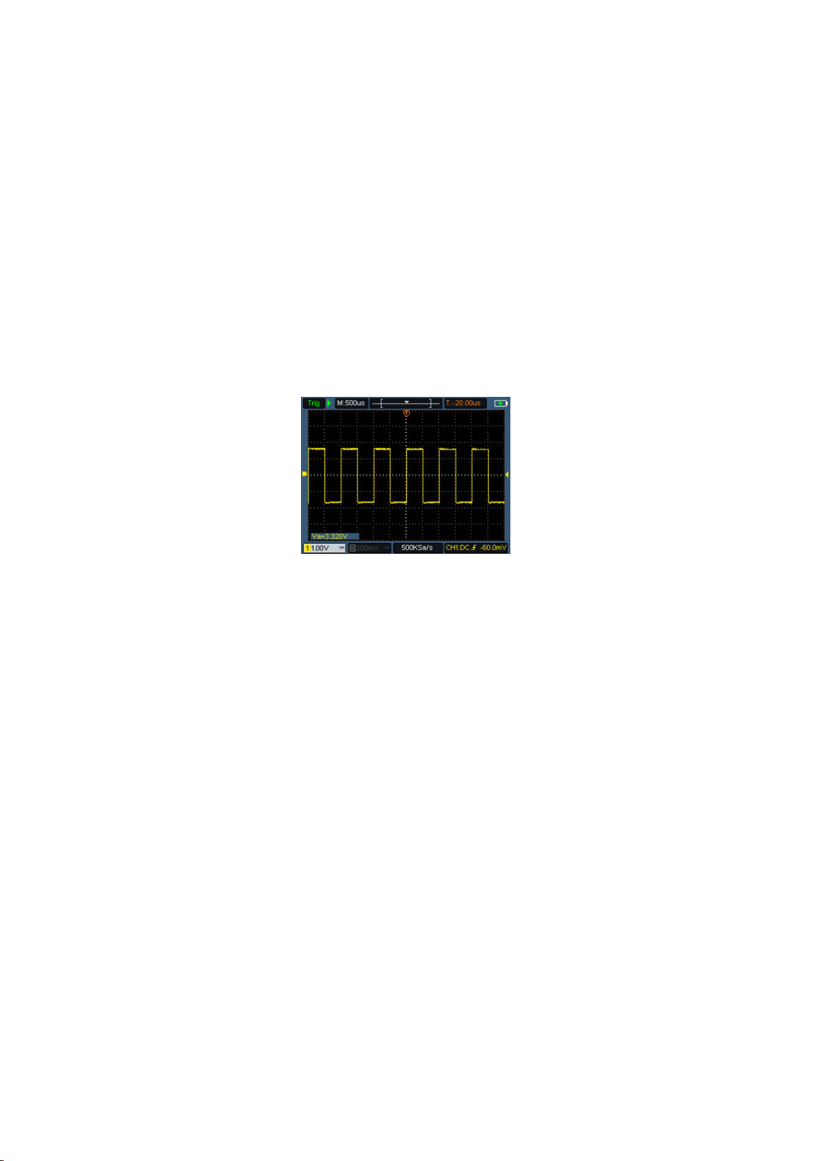
3. Press the "Auto" key on the front panel.
Within a few seconds, a square wave display (1kHz/3.3Vpp) can be seen, as
shown in Figure 0-1.
Figure 0-1: Automatic Setting
Repeat steps 2 and 3 on the CH2 channel.
Probe Compensation
When connecting the probe to any input channel for the first time, make this
adjustment to match the probe with the input channel. The probe without
compensation or deviation compensation will lead to measurement error. To
adjust the probe compensation, please follow the following steps:
1. Set the probe menu attenuation coefficient to 10X, and set the switch on the
probe to 10X (see "Probe Attenuation Coefficient Setting" in P9), and connect
with CH1. If a hook probe is used, make sure it is in close contact with the
probe. Connect the probe tip to the signal output connector of the probe
compensator, and connect the reference wire clamp to the ground wire
connector of the probe compensator, and then press the Auto key on the front
panel.
Page 17
12
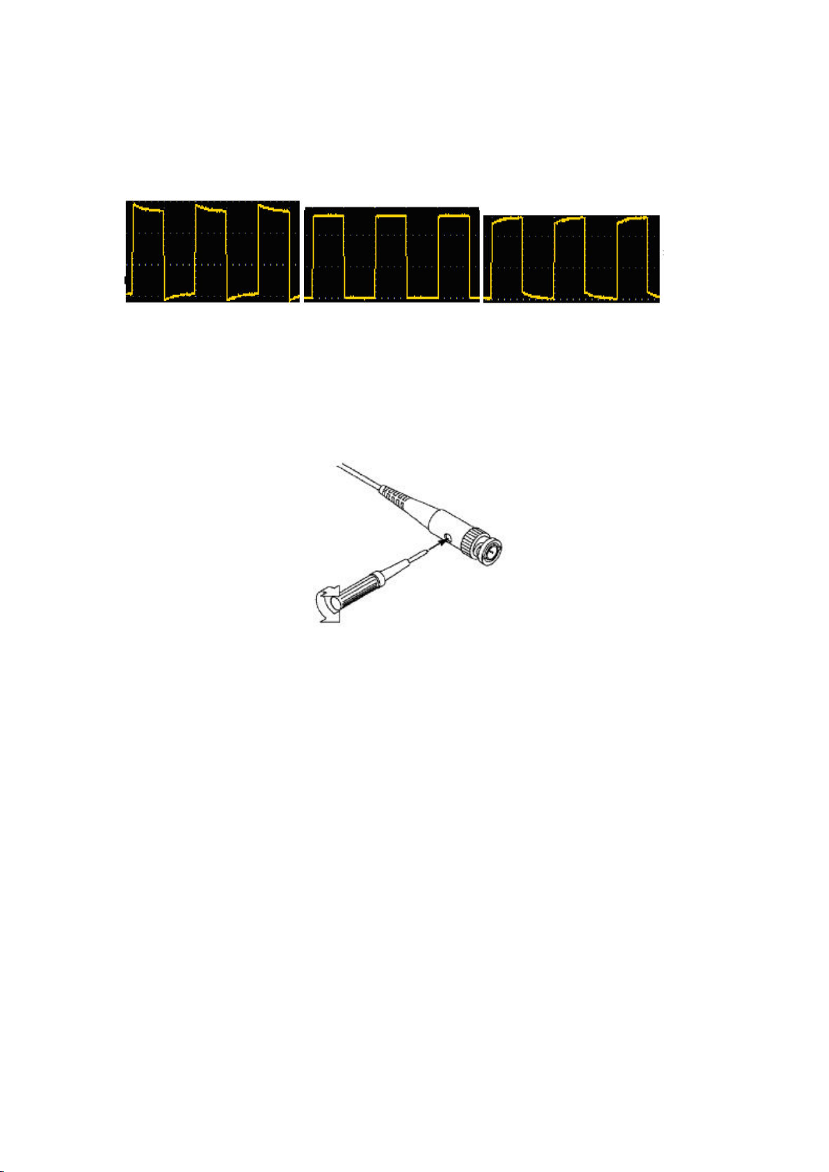
2. Check the displayed waveform and adjust the probe until the compensation
is correct. See Figure 0-2 and Figure 0-3.
Overcompensation Correct compensation
Under-compensation
Figure 0-2: Display Waveform of Probe Compensation
3. Repeat the steps if necessary.
Figure 0-3: Probe Adjustment
Probe Attenuation Coefficient Setting
The probe has a variety of attenuation coefficients, which will affect the vertical
position factor of the oscilloscope.
To change (check) the set value of probe attenuation coefficient in the
oscilloscope menu, please follow the steps below:
(1) Press the CH1/CH2 key to switch the channel to be used.
(2) Press the F3 to select the desired attenuation coefficient. This setting is
valid until it is changed again.
Page 18
13
Note: The preset setting of the probe attenuation coefficient in the
menu when the oscilloscope is delivered is 10X. Make sure
that the attenuation switch setting value on the probe is the
same as the probe attenuation coefficient option in the
oscilloscope menu.
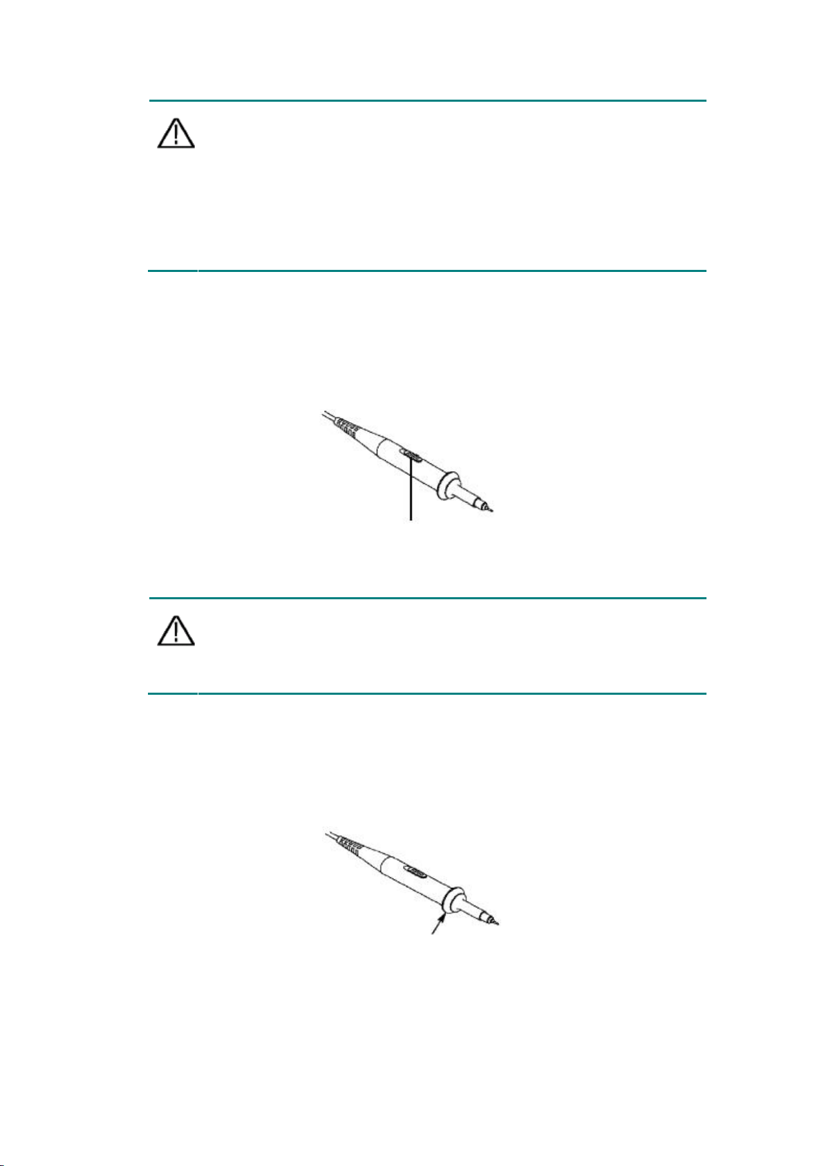
Note: When the attenuation switch is set to 1X, the probe limits the
bandwidth of the oscilloscope to 5 MHz. To use the full
bandwidth of the oscilloscope, be sure to set the switch to
10X.
The setting value of the probe switch is 1X and 10X. See Figure 04.
Figure 0-4: Probe Attenuation Switch
Safe Use of Probe
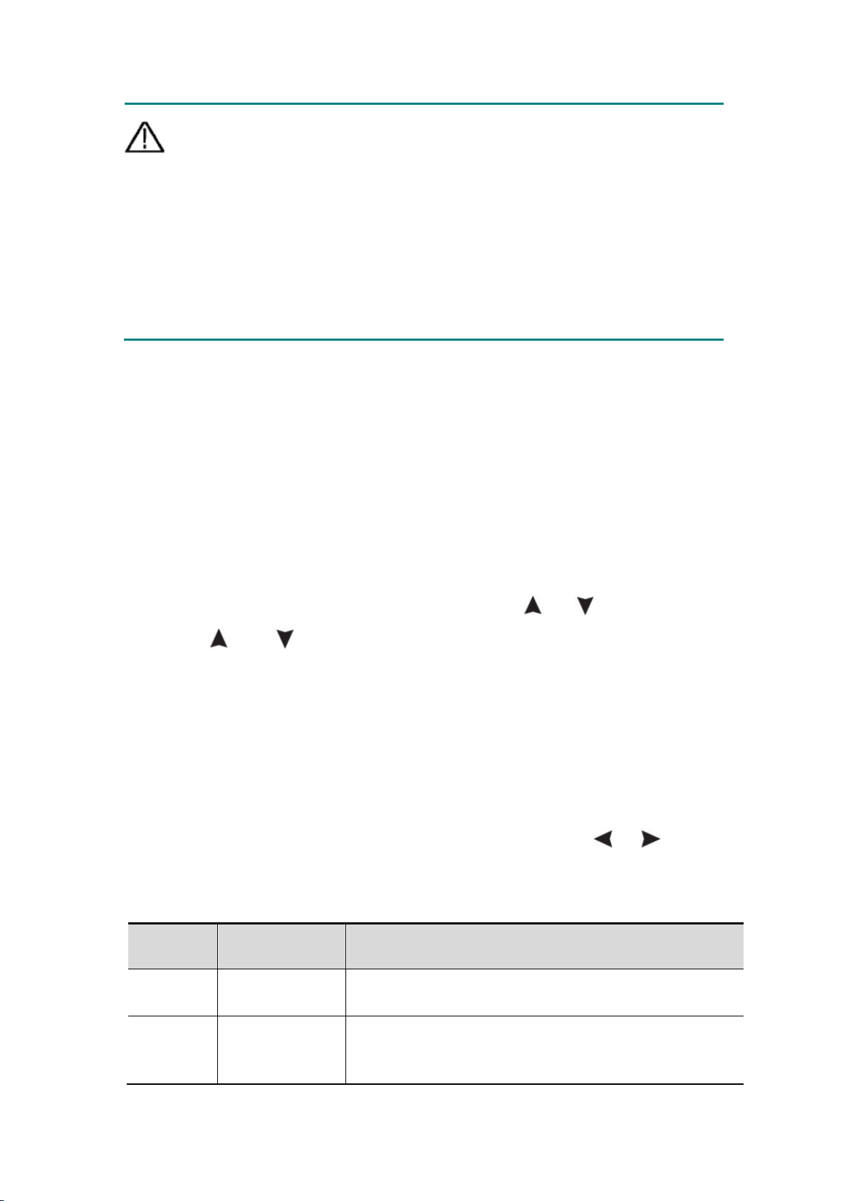
The safety ring surrounding the probe body provides a barrier to protect the
fingers from electric shocks. See Figure 05.
Figure 0-5: Finger Safety Ring of the Probe
Page 19
14
Warning: To prevent electric shock when using the probe, please keep
your fingers behind the safety ring on the probe body.
To prevent electric shock when using the probe, do not touch the
metal part of the probe head when the probe is connected to a
voltage source.
Before making any measurements, connect the probe to the
instrument and connect the ground terminal to the ground.
Function
menu
Setting
Description
Switch
On
Off
Turn on the waveform display.
Turn off the waveform display.
Coupling
DC
AC
Ground
The normal sampling method uses the AC and DC
components of the input signal.
Block the DC component of the input signal.
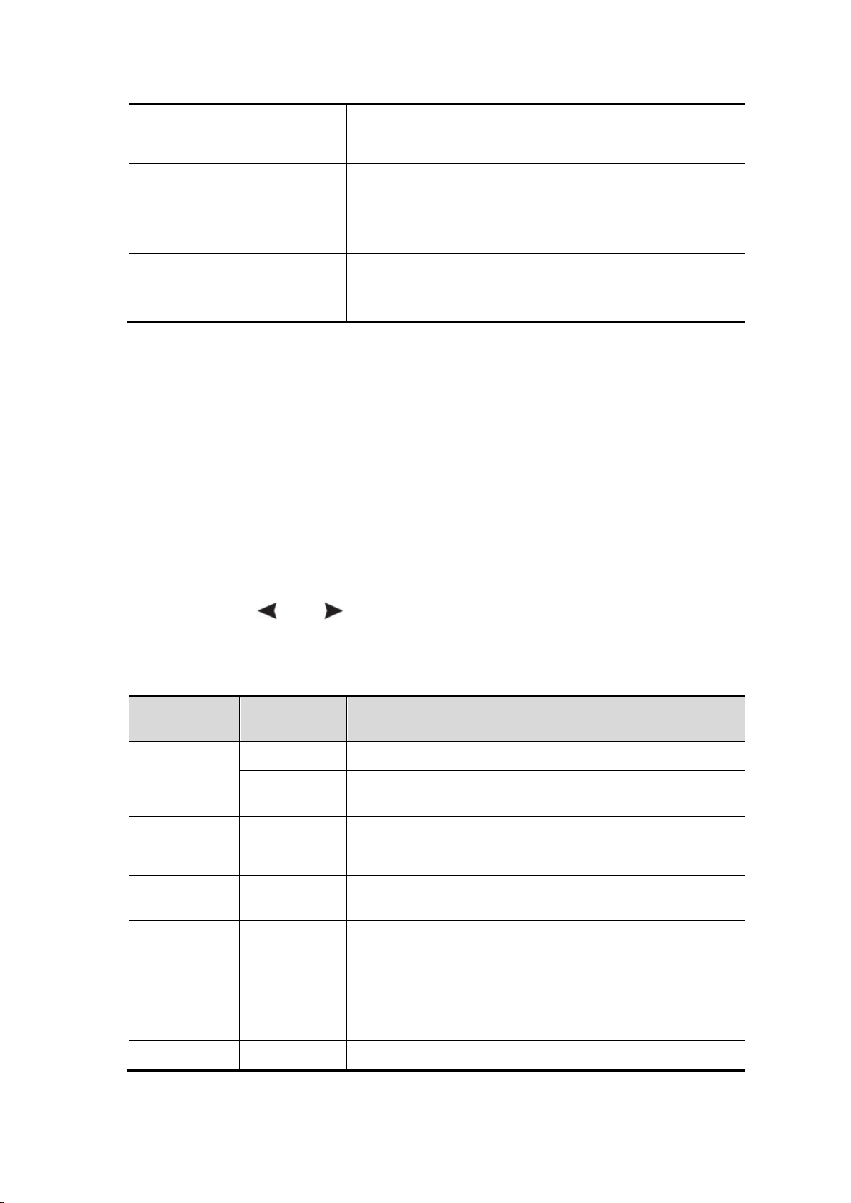
Vertical System
The vertical system can be used to adjust the vertical scale, the position and
other settings of the channel. Each channel has a separate vertical menu,
which can be set individually for each channel.
Vertical position
Press the CH1/CH2 keys to select the channel, and move the vertical position
of the selected channel up or down by pressing the
Press the
and direction keys at the same time to center the vertical
or
direction keys.
position.
Vertical Volt/Div Setting
The volt/div range is 10mV/div-10V/div (probe 1X), stepping in the 1-2-5 way,
or 100mV/div-100V/div (probe 10X), 1V/div-1000V/div (probe 100X ),
10V/div-10000V/div (probe 1000X).
Press the CH1/CH2 key to select the channel, and press the or
direction key to change the volts/div setting of the selected channel.
The description of the vertical system setting menu is as follows:
Page 20
15
Disconnect the input signal.
Probe
1X
10X
100X
1000X
Choose one of the values according to the probe
attenuation factor to keep the vertical scale
reading accurate.
Bandwidth
20M
Full bandwidth
Limit the bandwidth to 20MHz to reduce display
noise.
The bandwidth of the oscilloscope.
Function
menu
Setting
Description
Acquisition
mode
Sampling
Normal sampling method.
Peak
detection
Used to detect interference glitches and reduce
the possibility of confusion.
Record
length
4K points
8K points
Select the length to be recorded.
XY mode
On
Off
Choose to turn XY mode on or off.
1/2 Enter the next menu.
Refresh rate
High
Low
Set the refresh rate to "High" or "Low".
Center
horizontally
Set the horizontal trigger position in the middle of
the screen.
2/2 Return to the previous menu.
Horizontal System
Press the HOR key to enter the horizontal system setting menu. Use the
direction keys to change the horizontal scale (time base) and horizontal trigger
position. When changing the horizontal scale, the waveform is enlarged or
reduced relative to the center of the screen. When the horizontal position
changes, the position relative to the waveform trigger point changes.
Note: Press the
and direction keys at the same time to center the
horizontal position.
The description of the horizontal system setting menu is as follows:
Page 21
16
Function Menu
Description
Automatic
measurement
On
Off
Turn automatic measurement on
or off.
Source
CH1
CH2
Set the source.
Add
Delete
Frequency (F)□
Period (T)□
Amplitude (Va)□
Maximum (Ma)□
Minimum (Mi)□
Peak to Peak
value (Vpp)□
Average value
(V)□
Add or delete the selected
measurement type (displayed in
the lower left corner, up to 6
types).
Note: The unselected state is □;
The selected state is ■.
Function
Menu
Setting
Description
Type
CH1
CH2
Time
None
Select to display the CH1 cursor and menu.
Select to display the CH2 cursor and menu.
Select to display the time measurement cursor
and menu.
Turn off the cursor measurement.
Measuring System
Automatic Measurement
Press
types of measurement, and up to 6 types of measurement can be displayed at
the bottom left of the screen. Auto range includes frequency, period, amplitude,
maximum, minimum, peak-to-peak value, and average value.
The description of the automatic measurement Function Menu is as follows:
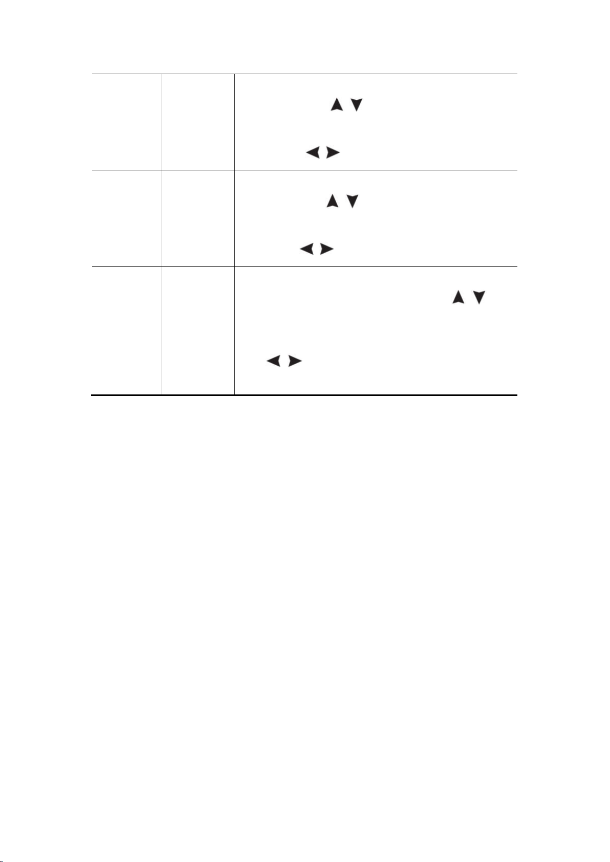
and the F1 key to realize automatic measurement. There are 7
Cursor Measurement
Press
The description of Cursor Measurement Menu is as follows:
and the F2 key to realize cursor measurement.
Page 22
17
A
When the type is selected as CH1 or CH2, press
the arrow keys
to move the cursor line A;
when the type is selected as Time, press the
arrow keys
to move the cursor line a.
B
When the type is selected as CH1 or CH2, press
the arrow keys
to move the cursor line B;
when the type is selected as Time, press the
arrow keys
to move the cursor line b.
AB
Link A and B. When the type is selected as CH1
or CH2, by pressing the arrow keys
two
cursors can be moved at the same time; when the
type is selected as Time, by pressing the arrow
keys
, two cursors can be moved at the
same time.
Trigger System
The trigger determines when the oscilloscope starts to acquire data and
display waveforms. Once the trigger is set correctly, it can convert an unstable
display into a meaningful waveform.
When the oscilloscope starts to acquire data, it first acquires enough data to
draw the waveform on the left side of the trigger point. The oscilloscope
continuously acquires data while waiting for the trigger condition to occur.
When a trigger is detected, the oscilloscope continuously acquires enough
data to draw a waveform on the right of the trigger point.
The trigger mode of this series of oscilloscopes is edge trigging.
The edge trigging mode is to trigger on the trigger electrical level of the edge of
the input signal, that is, trigger on the rising and falling edges of the input
signal.
Entering the edge trigging, the trigger setting information is displayed at the
Page 23
18
Function
Menu
Setting
Description
Source
CH1
CH2
Set Channel 1 as the source trigger signal.
Set Channel 2 as the source trigger signal.
Coupling
AC
DC
Set to prevent DC component from passing
through.
Set to allow all components to pass through.
Trigger
type
Automatic
Normal
Single
Waveforms can be acquired without detecting
trigger conditions.
The waveform is acquired only when the trigger
conditions are met.
When a trigger is detected, a waveform is sampled
and then stopped.
1/2 Enter the next menu.
Edge
Rising edge
Falling edge
Trigger on the rising edge of the signal.
Trigger on the falling edge of the signal.
Trigger
centered
The trigger position is set in the middle of the
waveform.
Force
trigger
Forced trigger key, which forcibly generates a
trigger signal, mainly used in the "normal" and
"single" modes of the trigger mode.
2/2 Return to the previous menu.
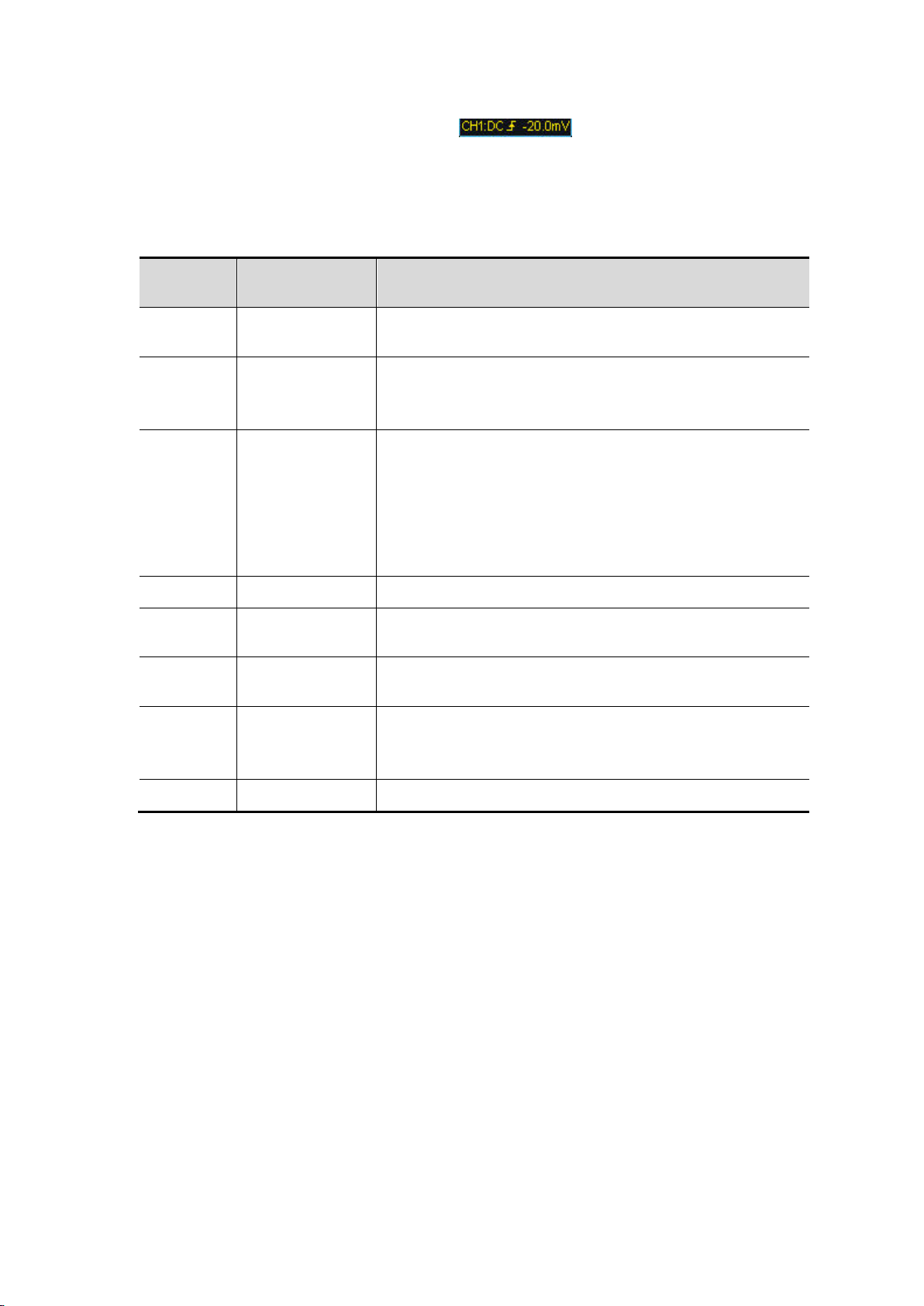
bottom right corner of the screen, e.g. . It indicates that the
trigger type is rising edge, the trigger source is CH1, the trigger coupling is DC,
and the trigger electrical level is -20.0mV.
The description of the trigger system setting menu is as follows:
Trigger electrical level: The amplitude level that the signal must cross when
setting the waveform acquisition. Press the Trig/
menu, and press the Up or Down key to move the trigger electrical level up
and down.
Save Settings
Press the Save key to enter the save function menu. By operating the save
function menu, oscilloscope settings, reference waveforms, and files can be
△ key to enter the trigger
Page 24
19
Function
Menu
Setting
Description
Target
S1
S2
S3
S4
Set waveform name.
Save
Save the current parameter settings of the
oscilloscope to the internal memory.
Call
Call the settings saved in the current storage
location.
Function
Menu
Setting
Description
Source
CH1
CH2
Select the reference waveform to be saved.
Target
R1
R2
R3
R4
Set waveform name.
Display
On
Off
Call or close the waveform of the current target
address in the internal memory. When it displays
"On", if there is a stored waveform at the current
address, the waveform will be displayed, and the
address number and waveform related
information will be displayed in the upper left
corner; if the current address is not stored, it will
display "Address No.: No waveform saved".
Save
Save the reference waveform of the source to th
stored.
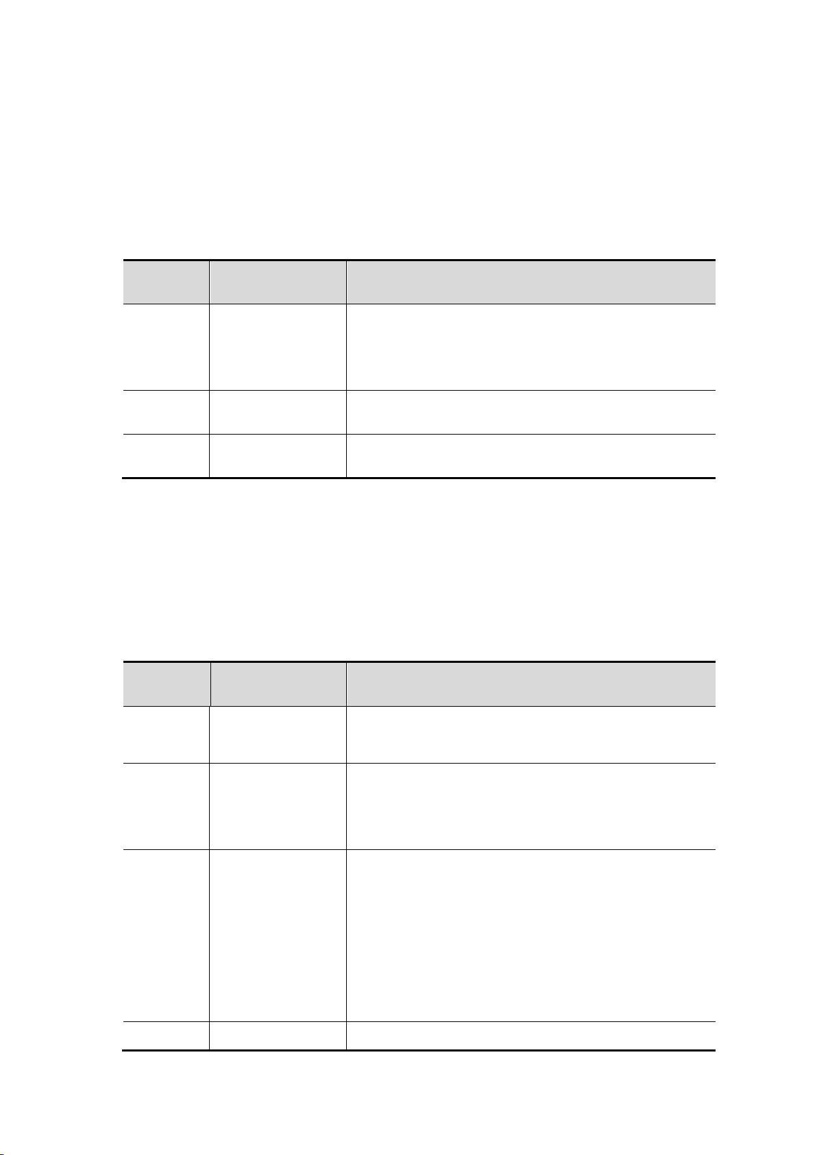
⚫ Settings
Any setting can be saved inside the oscilloscope, and restore settings can also
be called.
The description of Setting menu is as follows:
⚫ Reference Waveform
The actual waveform can be compared with the reference waveform to find out
the difference. Press the Save key to enter the save function menu, and press
F2 to select the reference waveform to enter the reference waveform menu.
The description of the Reference Waveform menu is as follows:
Page 25
20
e memory.
Function
Menu
Setting
Description
File
Wavef
orm
File
name
weve1
weve2
weve3
weve4
Select the file name of the stored
waveform.
Source
CH1
CH2
Select the waveform channel to be
saved.
Save
Store the waveform of the source in
a csv file named by the specified file
name.
Image
File
name
image1
image2
image3
image4
Select the file name of the stored
wave image.
Save
Store the current screen image in
the bmp file named by the specified
file name.
Function
Menu
Setting
Description
Luminance
10% - 100%
Set the screen backlight to increase in a 10%
cycle.
Backlight
time
30s
60s
Set the screen backlight luminance time.
Unlimited means always on.
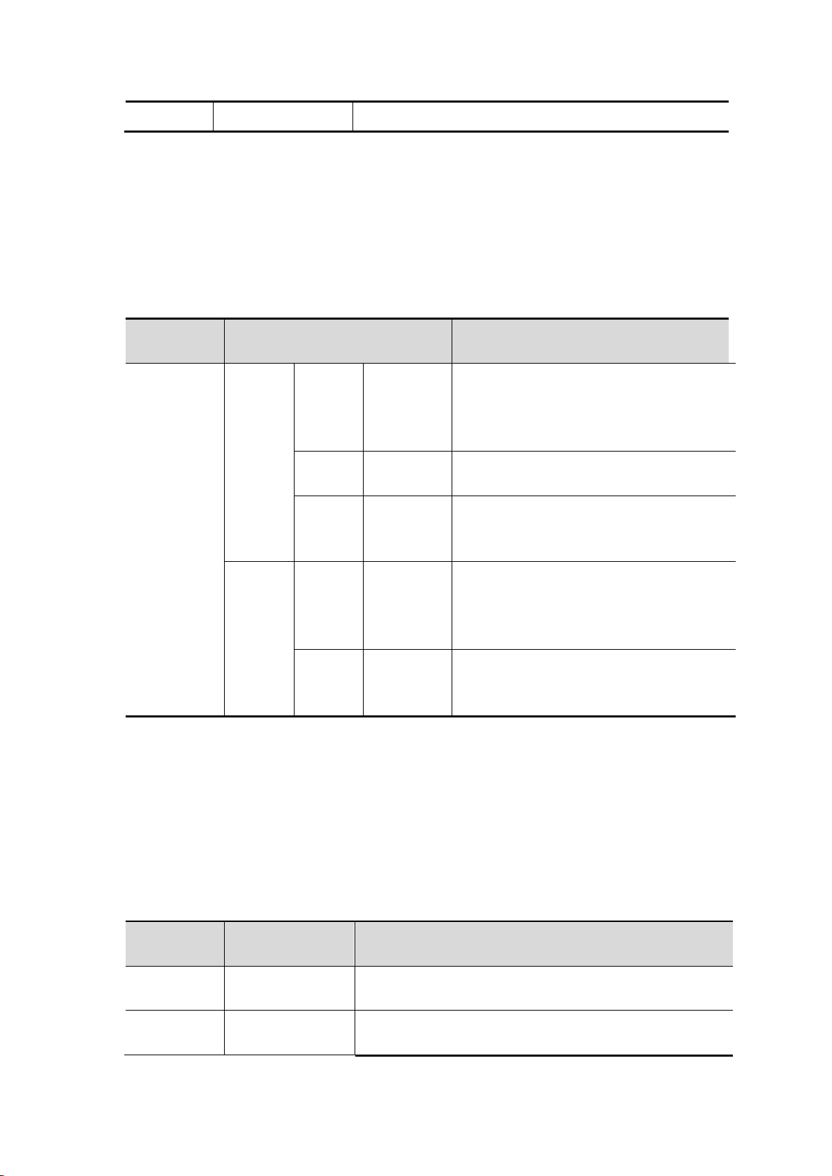
⚫ File
The file can be saved as waveform or image. The waveform and image can be
read by plugging and unplugging the USB data cable or selecting MSC in the
USB option on the next page of system settings.
The description of File menu is as follows:
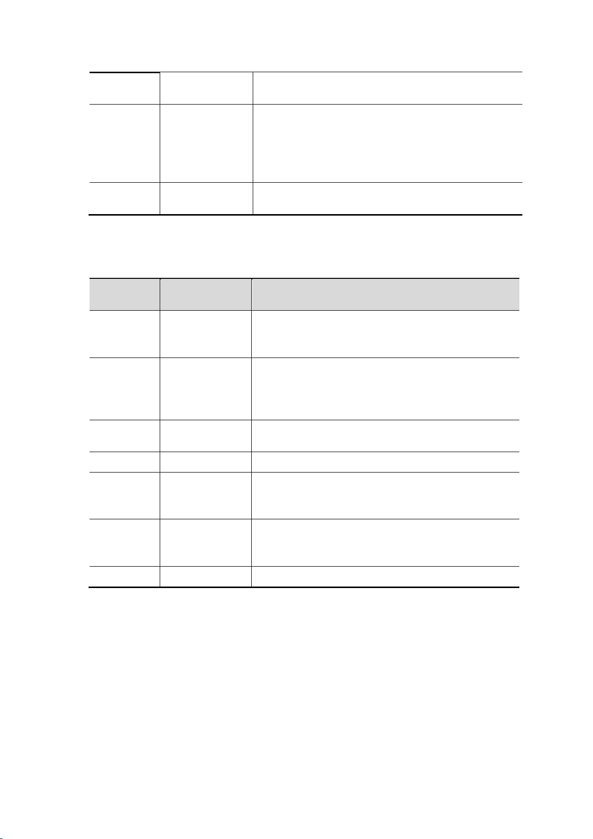
System Settings
Press the System key to enter the system function menu.
⚫ Display
The description of the menu is as follows:
Page 26
21
120s
Unlimited
Menu time
5s
10s
20s
30s
60s
Set the menu display time.
Elapsed
runtime
00h:00m
Display how long it has been powered on.
Function
Menu
Setting
Description
Language
Simplified
Chinese
English
Set the menu language.
Shutdown
time
10 minutes
30 minutes
60 minutes
Unlimited
Set the automatic shutdown time. Unlimited
means no shutdown. Please pay attention to this
setting if you use the battery only.
Buzzer
On
Off
Buzzer switch. The buzzer is turned on by
default in the multimeter mode.
1/2 Enter the next menu
About
After pressing this key, the instrument model,
serial number, version, and checksum can be
displayed.
System
upgrade
To upgrade the system. The version of the
upgrade package must be higher than the
version of the instrument itself.
2/2 Return to the previous menu
⚫ System
The description of the menu is as follows:
⚫ Default Settings
Press the System key to enter the system setting menu. Select F3 "Default
Setting", the screen will prompt "press < F3 > to execute the default setting,
otherwise press the return key". If you need to perform the default setting,
press F3 again to complete the default setting, otherwise, press the return key.
⚫ USB Connection
Press the System key to enter the system setting menu. Select F4 to enter the
Page 27

22
next page. Press F1 to select HID or MSC.
1) MSC [Mass Storage Class] is used to make USB read the files stored in
the built-in memory.
2) HID [Human interface Device] is used to select the oscilloscope device as
the host computer to control and communicate with the computer.
⚫ Factory Settings
To set the factory settings, press the System key. Press the menu selection
key F4 to enter the next page. Press F2 two times to confirm the execution.
The factory settings are restored.
⚫ Automatic Correction
The automatic correction program can quickly make the oscilloscope reach the
best condition to obtain the most accurate measurement value. You can
execute this program at any time, but if the ambient temperature variation
range reaches or exceeds 5℃, you must execute this program.
To perform automatic correction, disconnect all probes or wires from the input
connector. Then, press the System key. Press the menu selection key F4 to
enter the next page, and press the menu selection key F3. Perform automatic
correction after confirming readiness.
5. How to Use the Multimeter
About This Chapter
This chapter introduces the multimeter function of the oscilloscope step by
step, and provides some basic examples of basic operations and how to use
the menu.
Instrument Interface
The multimeter uses four 4-mm safety banana plug input ends: A, mA, COM,
and
Multimeter interface:
.
Page 28
23
1
2
3
4
5
6
7
8
9
11 10
12
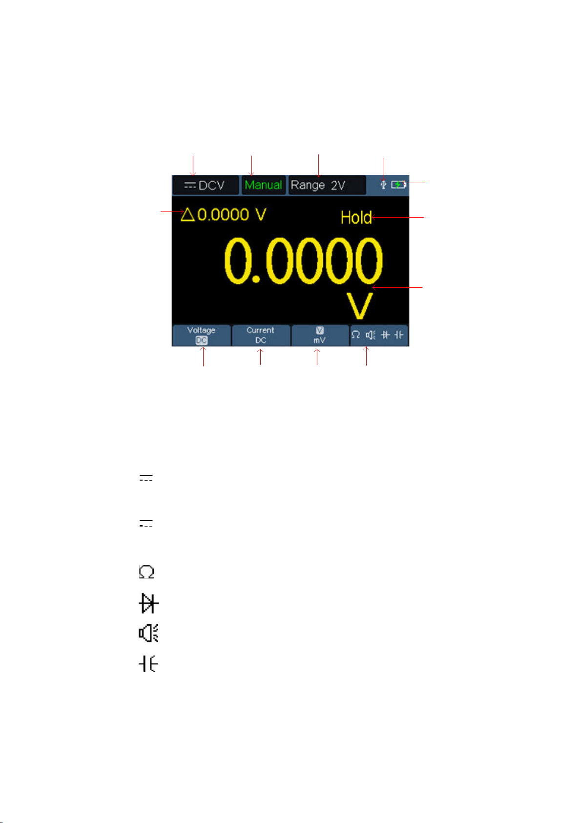
Multimeter Interface
Description:
1. Measurement type indication:
DCV ------ DC voltage measurement
~ ACV ------ AC voltage measurement
DCA ------ DC current measurement
~ ACA ------ AC current measurement
Resist ------ Resistance measurement
Diode ------ Diode measurement
Cont ------ On/Off measurement
Cap ------ Capacitance measurement
2.Range indication: Manual means manual range; Auto means automatic
range.
3. Current measurement range.
Page 29

24
4. Indicating that there is a USB cable inserted.
5. Battery power indication.
6. “Hold” can keep the current reading on the display.
7. Measurement value and unit.
8. Display of switching resistance, buzzer, diode and capacitance
measurement function.
9. The selected range V or mV in voltage measurement; the selected current
range A or mA in current measurement.
10. To choose AC or DC voltage measurement.
11. To choose to AC or DC current measurement.
12. Display of relative value measurement function (only available when
measuring DC current, DC voltage and resistance).
Page 30
25
6. How to Use the Waveform Generator(optional)
The instrument can provide 4 basic waveforms, sine wave, square wave,
ramp wave, pulse wave, and 8 arbitrary waveforms.
Connect the output
Press the Mode button to switch the instrument interface to the waveform
generator function interface. Check whether the upper left corner of the
screen is ON, if it is OFF, press the Run/Stop key to switch.
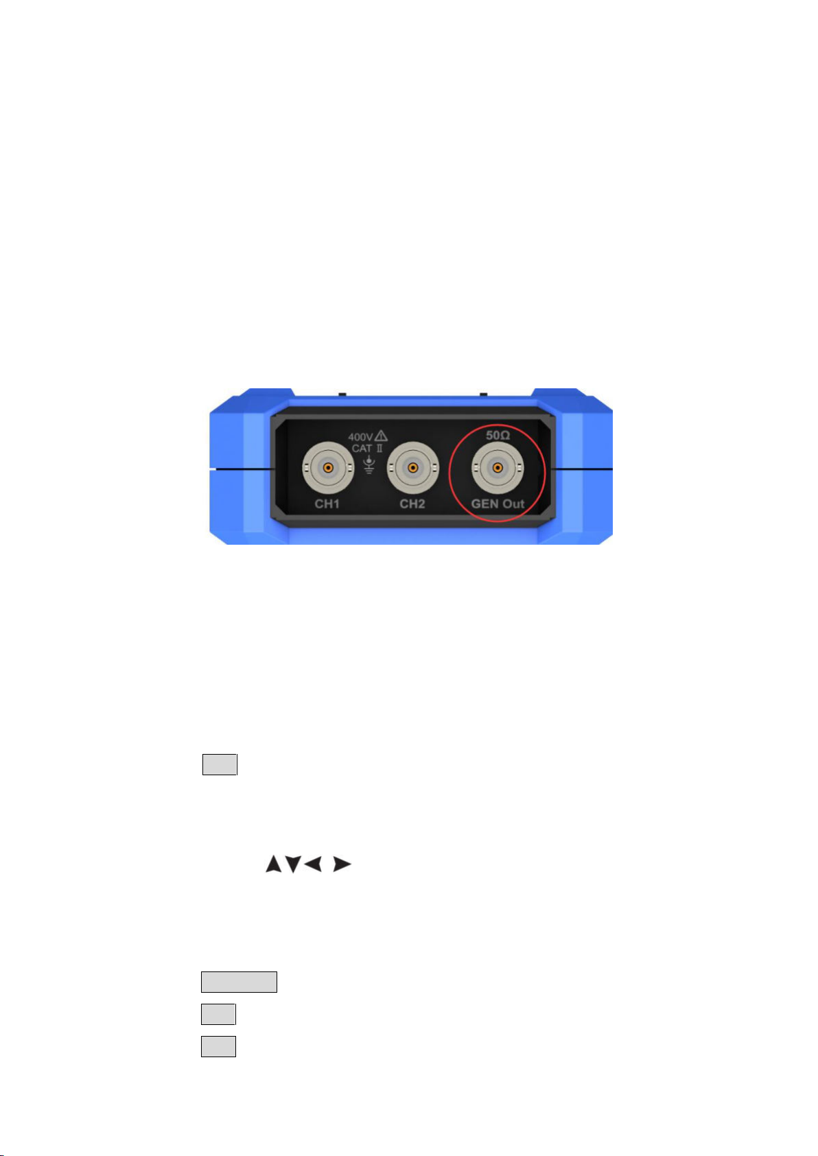
Connect the BNC cable to the port marked GEN Out in the top of the
oscilloscope.
图 6-1:Generator Output Ports
To observe the output of the waveform generator, connect the other end of
the BNC cable to the signal input connector of the oscilloscope.
Set the waveform
(1) Press the Mode button to switch the instrument interface to the waveform
generator function interface.
(2) Press F1 to select the desired waveform, and the screen will display
the corresponding waveform setting menu.
(3) Set the parameters of the desired waveform through the operation panel
F2-F4 and the
Set the load
panel keys.
Press the System key to enter the system function menu.
Press the F4 key to enter the next page of menu.
Press the F3 key to switch High Z / *Ω ("*" represents a value, the default
Page 31
26
is 50Ω).
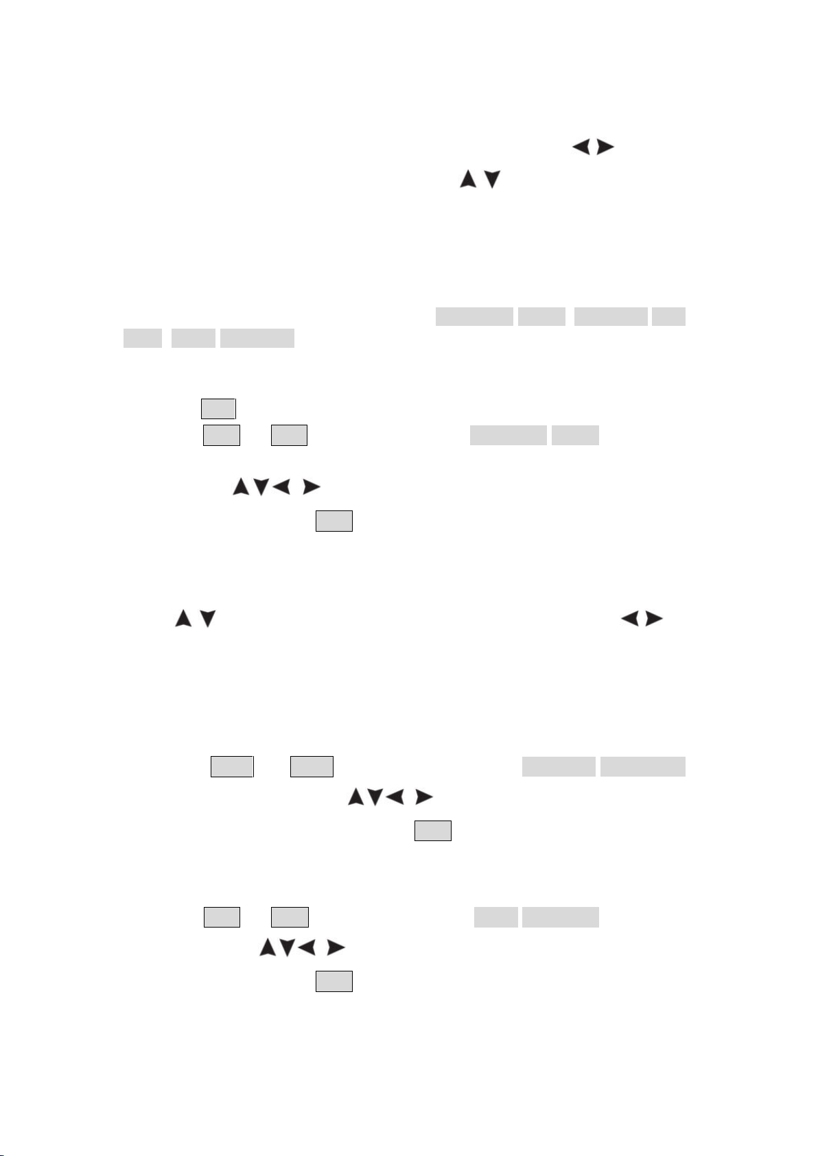
Note: To change the load value, after selecting *Ω, press
key to move the cursor left and right; press
the value. The load range is 1 Ω - 10 kΩ.
/ direction key to change
/ direction
Output the sine waveform
The sine waveform setting menu includes: Frequency/Period, Amplitude/High
Level, Offset/Low Level.
Set the Frequency / Period
Press the F1 key to enter the sine waveform setting interface.
Press the F3 or F4 key to switch to the Frequency/Period parameter,
the selected parameter item will be displayed in green (the same below), and
then use the
parameter column. Press F2 to switch between Frequency / Period.
direction keys to set the desired value in the
Use the direction keys to change the selected parameter value:
Press
move the cursor left and right to different numerical digits.
Note: When setting parameters, long press the key to accelerate the
change of the value.
/ to increase or decrease the value at the cursor. Press / to
Set the Amplitude / High Level
Press the F3 or F4 key to switch to the Amplitude/High Level
parameter, and then use the direction keys to set the desired
value in the parameter column. Press F2 to switch between Amplitude /
High Level.
Set the Offset / Low Level
Press the F3 or F4 key to switch to the Offset/Low Level parameter,
and then use the direction keys to set the desired value in the
parameter column. Press F2 to switch between Offset / Low Level.
Page 32
27
Output the square waveform
Press the F1 key to enter the square waveform setting interface.
The square waveform setting menu includes: Frequency/Period, Start Phase,
Amplitude/High Level, Offset/Low Level.
For the setting frequency/period, amplitude/high level, offset/low level, please
refer to Output the sine waveform on page 26.
Output the ramp waveform
Press the F1 key to enter the ramp waveform setting interface.
The ramp waveform setting menu includes: Frequency/Period, Start Phase,
Amplitude/High Level, Offset/Low Level, Symmetry.
For the setting frequency/period, amplitude/high level, offset/low level, please
refer to Output the sine waveform on page 26.
Set the symmetry of the ramp waveform
Press the F3 or F4 key to switch to the Symmetry parameter, use the
direction keys to set the desired value in the parameter column.
Output the pulse waveform
Press the F1 key to enter the pulse waveform setting interface.
The pulse waveform setting menu includes: Frequency/Period, Start Phase,
Amplitude/High Level, Offset/Low Level, Pulse Width/Duty Cycle, Rise
Time/Fall Time.
For the setting frequency/period, amplitude/high level, offset/low level, please
refer to Output the sine waveform on page 26.
Set the Pulse Width / Duty Cycle of the pulse waveform
Press the F3 or F4 key to switch to the Pulse Width/Duty Cycle
parameter, use the direction keys to set the desired value in the
parameter column. Press F2 to switch between Pulse Width / Duty Cycle.
Set the Rise Time/Fall Time
Press the F3 or F4 key to switch to the Rise Time/Fall Time parameter,
use the direction keys to set the desired value in the parameter
Page 33
28
Name
Explanation
Sinc
Sinc function
Bessely
BesselII function
Besselj
BesselI function
StairUp
Stair-up waveform
StairUD
Stair-up and stair-down waveform
StairDn
Stair-down waveform
AttALT
Gain oscillation curve
AmpALT
Attenuation oscillation curve
column. Press F2 to switch between Rise Time / Fall Time.
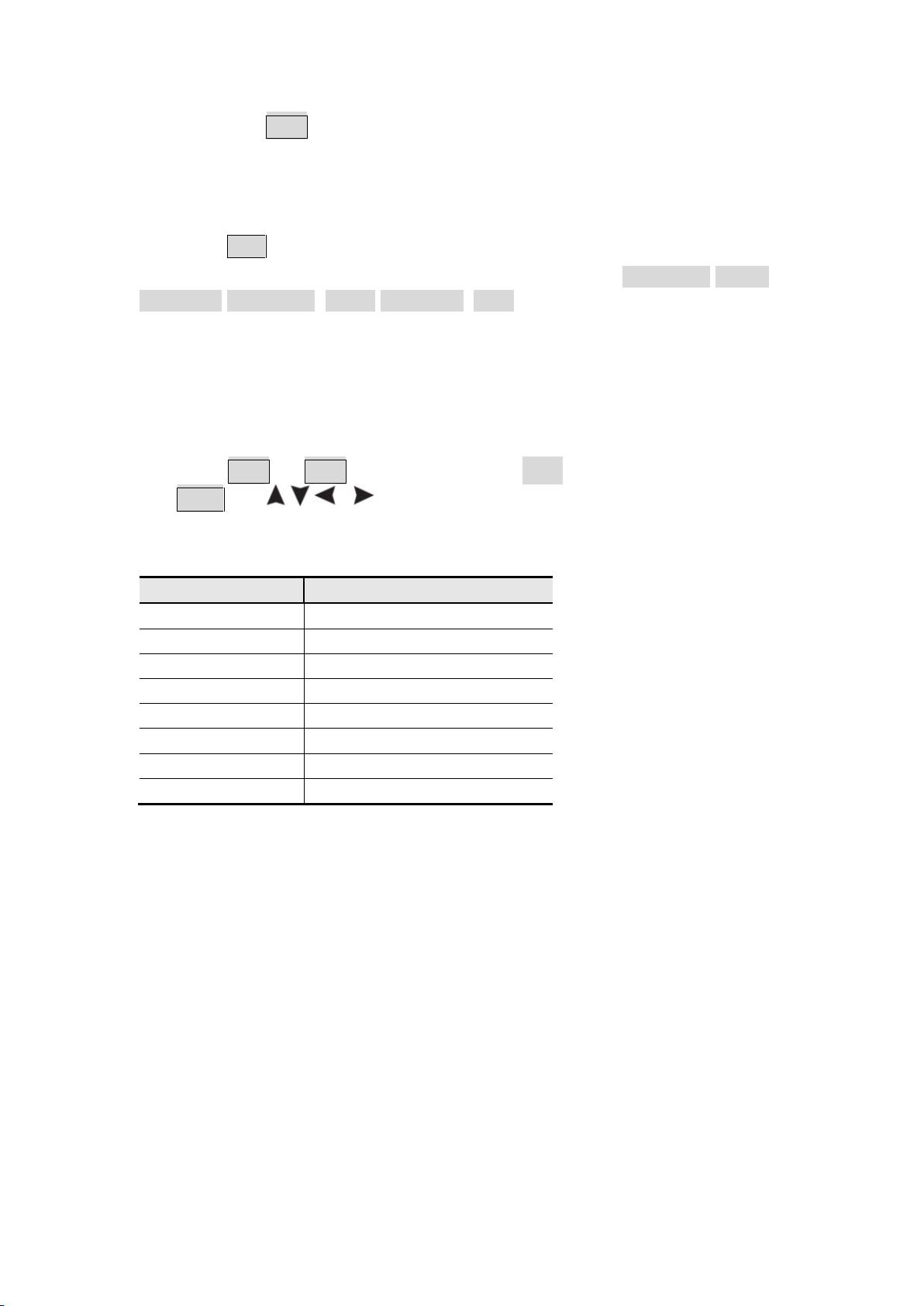
Output the Arbitrary waveform
Press the F1 key to enter the arbitrary waveform setting interface.
The arbitrary waveform setting menu includes: Frequency/Period,
Amplitude/High Level, Offset/Low Level, Type.
For the setting frequency/period, amplitude/high level, offset/low level, please
refer to Output the sine waveform on page 26.
Type (built-in waveform)
The system has 8 built-in waveforms. To select the built-in waveform:
Press the F3 or F4 key to switch to the Type parameter, and then use
the F2 or direction keys to select the desired built-in
waveform in the parameter column.
Built-in waveform list
Page 34
29
7. Communication with PC
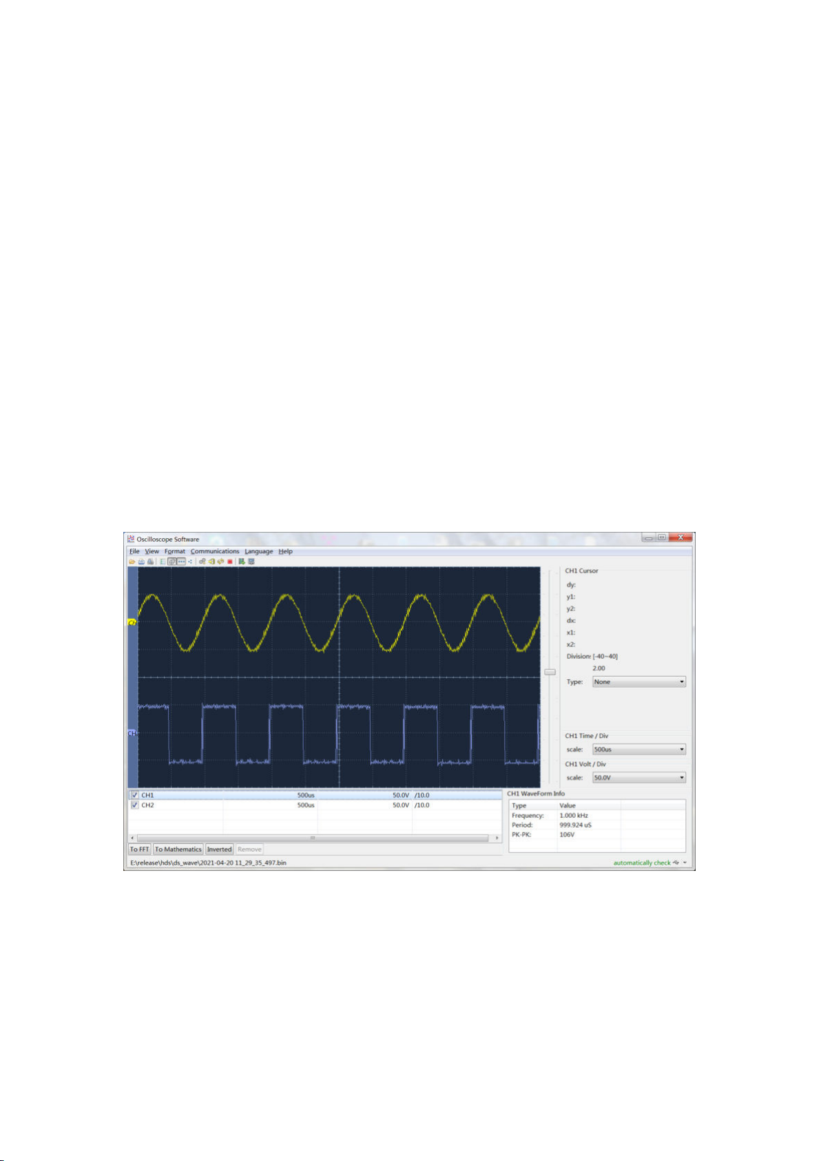
The oscilloscope supports communications with a PC through USB. You can
use the Oscilloscope communication software to store, analyze, display the
data and remote control.
To learn about how to operate the software, you can push F1 in the software
to open the help document.
Here is how to connect with PC. Please download the oscilloscope
communication software on our official download website and install it to your
computer.
(1) Connection: Use a USB data cable to connect the USB Device port in
the right panel of the Oscilloscope to the USB port of a PC.
(2) Install the driver: Run the Oscilloscope communication software on PC,
push F1 to open the help document. Follow the steps of title "I. Device
connection" in the document to install the driver.
(3) Port setting of the software: Run the Oscilloscope software; click
"Communications" on the menu bar, choose "Ports-Settings", in the
setting dialog, choose "Connect using" as "USB". After connect
successfully, the connection information in the bottom right corner of the
software will turn green.
Figure 7-1 Connect with PC through USB port
Page 35

30
8. Troubleshooting
1. The oscilloscope cannot be turned on.
It may be that the battery is completely exhausted. At this time, even if the
oscilloscope is powered by the power adapter, the oscilloscope cannot be
turned on. You need to charge the battery first, and do not turn on the
oscilloscope. Wait for about 15 minutes, and then try to turn on the
oscilloscope. If the oscilloscope still cannot be turned on, please contact us to
serve you.
2. The oscilloscope turns off after a few seconds of startup.
It may be that the battery is exhausted. Check the battery symbol at the top
left of the screen. symbol indicates that the battery is exhausted and must
be charged.
3. After switching to the multimeter, the measurement type is displayed
as E.
It may be that the measurement type was not selected. At this time, press F4,
the measurement type should display the corresponding measurement type.
If E is still displayed, restart the oscilloscope.
4. In the oscilloscope state, the measured voltage amplitude value is 10
times larger or smaller than the actual value.
Check whether the channel attenuation coefficient is consistent with the
actual probe error ratio.
5. In the oscilloscope state, there is a waveform display, but it cannot be
stabilized.
⚫ Check whether the source item in the trigger mode menu is consistent
with the signal channel actually used.
⚫ Check whether the trigger electrical level has exceeded the waveform
range. Only by setting the parameters reasonably, the waveform can be
displayed stably.
6. In the oscilloscope state, nothing is displayed after pressing
Page 36

31
RUN/STOP.
Check whether the trigger mode of the trigger mode menu is normal or single,
and the trigger electrical level is out of the waveform range. If so, center the
trigger electrical level or set the trigger mode to automatic. In addition, you
can press Auto to automatically complete the above settings.
7. In the oscilloscope state, the display speed becomes slower when the
average value sampling is set in the acquisition mode or the duration is
set longer in the display settings.
It is normal.
Page 37
32
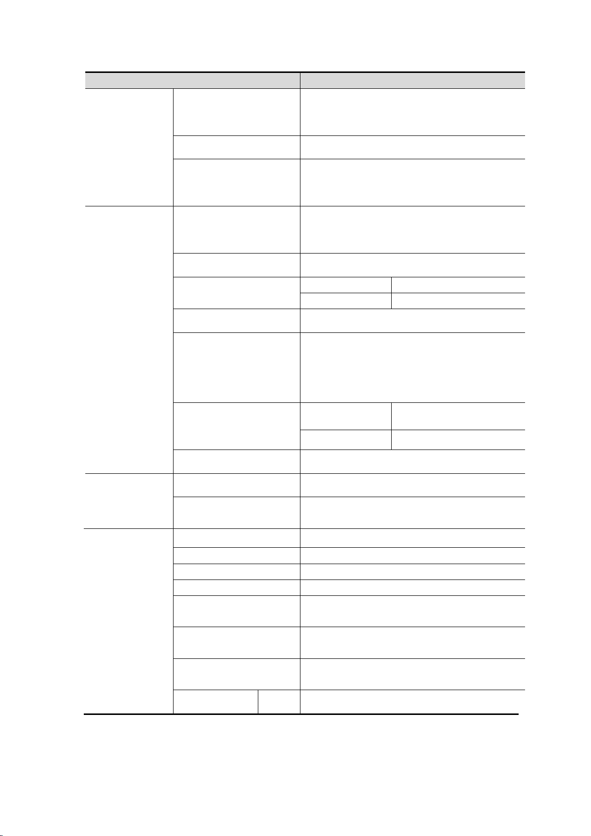
Characteristics
Description
Bandwidth
HDS242(S)
40 MHz
HDS272(S)
70 MHz
Channel
2
Sampling
Sampling method
Sampling, peak detection
Real-time sampling
rate
125 MSa/s (Dual channel)
250 MSa/s (Single channel)
Waveform refresh rate
10,000 wfms/s
Input
Input coupling
DC, AC, ground
Input impedance
(DC coupling)
1 MΩ±2%, in parallel with 16 pF±10 pF
Probe attenuation
1X 、10X、100X、1000X
Maximu input voltage
400 V (DC + AC ,PK - PK)
Bandwidth limit
20 MHz ,Full bandwidth
Horizontal
Sampling rate range
0.25 Sa/s~250 MSa/s
Waveform
interpolation
(Sinx)/x
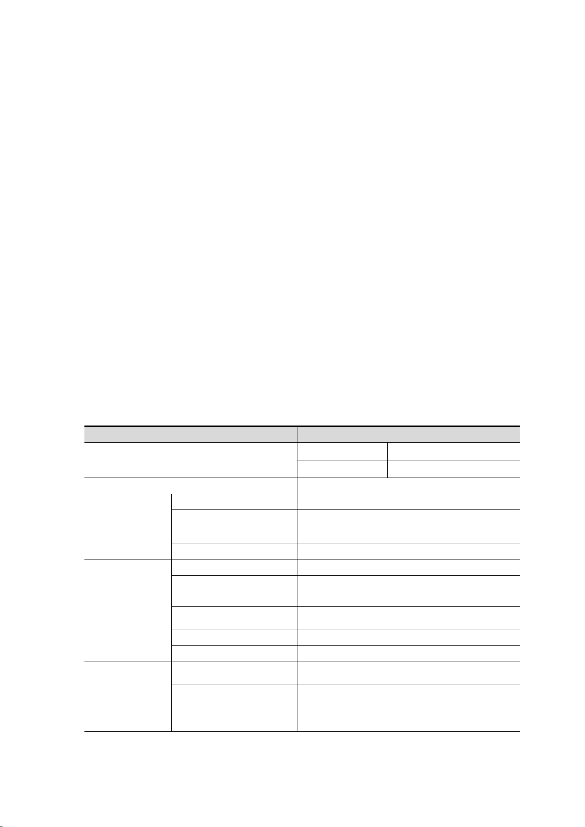
9. Technical Specifications
Unless otherwise stated, all technical specifications are applicable to the
probe with the attenuation switch set to 10X and this series of oscilloscopes.
The oscilloscope must first meet the following two conditions to meet these
specifications and standards:
■ The instrument must be operated continuously for more than 30
minutes at the specified operating temperature.
■ If the operating temperature variation range reaches or exceeds
5℃, the system function menu must be opened to execute the
"automatic correction" program (see automatic correction in "System
Settings" on P18).
All specifications are guaranteed except those marked "typical".
Oscilloscope
Page 38
33
Characteristics
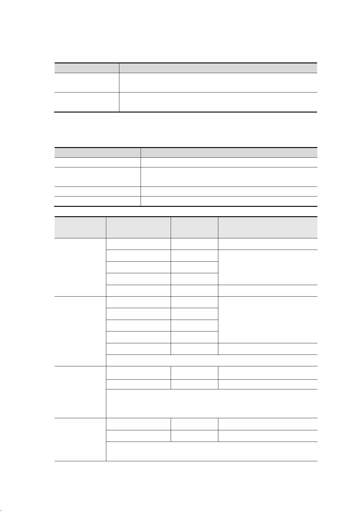
Description
Sweep speed range
(S/div)
5ns/div - 1000s/div,
Stepping in the 1-2-5 way
Time base accuracy
±100 ppm
Record length
Single channel: up to 8K
Dual channel: 4K
Vertical
Sensitivity
(Volt/div) range
10 mV/div~10 V/div
Displacement range
±6 div
Analog bandwidth
HDS242(S)
40 MHz
HDS272(S)
70 MHz
Single bandwidth
Full bandwidth
Low frequency
response
(AC coupling, -3dB)
≥10 Hz
Rise time
(typical on BNC)
HDS242(S)
≤ 8 ns
HDS272(S)
≤ 5 ns
DC gain accuracy
3%
Measurement
Cursor
ΔV, ΔT, ΔT&ΔV between
Automatic
Period, Frequency, Mean, PK-PK,
Max, Min, Amplitude
Trigging
Source
CH1, CH2
Type
Edge
Coupling
DC, AC
Trigger type
Auto, normal, single
Trigger electrical level
range
±4 divs from the center of the screen
Trigger electrical level
accuracy
±0.3 div
Trigger displacement
According to Record length and time
base
Edge trigging
Slope
Rising edge, falling edge
Page 39
34
Characteristics
Description
Output voltage
(typical)
3.3Vpp, High-Z
Frequency
(typical)
Square wave 1 kHz (±1%)
Characteristics
Description
Digital display
20,000 readings
Measurement type
Voltage, current, resistance, capacitance, on/off,
diode
Maximum lnput voltage
AC : 750V DC : 1000V
Maximum lnput current
AC : 10A DC : 10A
Basic
function
Range
Minimum
resolution
Accuracy
DC voltage
200.00mV
0.01mV
±(0.5%+5dig)
2.0000V
0.1mV
±(0.3%+3dig)
20.000V
1mV
200.00V
10mV
1000.0V
0.1V
±(0.5%+2dig)
AC voltage
200.00mV
0.01mV
±(0.8%+5dig)
2.0000V
0.1mV
20.000V
1mV
200.00V
10mV
750.0V
0.1V
± ( 1%+5dig)
frequency range:40Hz-1000Hz
DC current
200.00mA
10μA
±(0.8%+2dig)
10.000A
1mA
±(2.5%+2dig)
Overload protection:
Ma function: self-healing fuse 400 mA/250 V; Ampere function:
10A/600 V, D5.2*20, fast-acting fuse
AC current
200.00mA
10μA
± ( 1%+5dig)
10.000A
1mA
± ( 2.8%+5dig)
frequency range:40Hz-1000Hz
Overload protection:
The output of the probe compensator:
Multimeter
Page 40
35
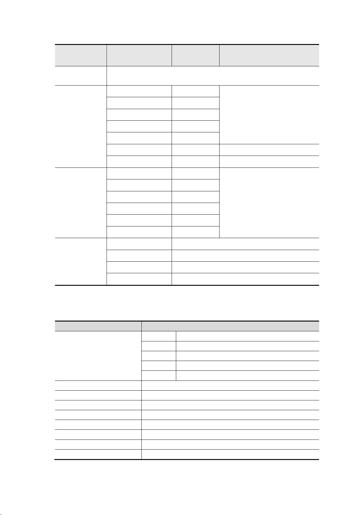
Basic
function
Range
Minimum
resolution
Accuracy
Ma function: self-healing fuse 400 mA/250 V; Ampere function:
10A/600 V, D5.2*20, fast-acting fuse
Resistance
200.00Ω
0.01Ω
±(0.8%+3dig)
2.0000kΩ
0.1Ω
20.000kΩ
1Ω
200.00kΩ
10Ω
2.0000MΩ
100Ω
20.000MΩ
1kΩ
± ( 1%+3dig)
100.00MΩ
10kΩ
± ( 3%+3dig)
Capacitance
20.000nF
1pF
±(3.0%+10dig)
200.00nF
10pF
2.0000μF
100pF
20.000μF
1nF
200.00μF
10nF
2.0000mF
100nF
Others
On/Off test
√ (<50Ω)
Diode test
√(<0-2V)
Auto range
√
TRMS
√
Characteristics
Description
Waveform Frequency
Sine
0.1Hz~25MHz
Square
0.1Hz~5MHz
Ramp
0.1Hz~1MHz
Pulse
0.1Hz~5MHz
EXP
0.1Hz~5MHz
Sampling
125MSa/s
Amplitude(50Ω)
0.01Vpp ~ 2.5Vpp
DC offset(High Z)
±(2.5V – Amplitude Vpp/2)
Frequency Resolution
0.01%
Channel
1
Waveform Depth
8k
Vertical Resolution
14 bit
Output Impedance
50 Ω
Arbitrary Waveform Generator ( (Optional)
Page 41

36
Characteristics
Description
Display type
3.5-inch color LCD display
Display resolution
320 horizontal × 240 vertical pixels
Display color
65536 colors
Display Contrast
Adjustable
Characteristics
Description
Power supply
100 - 240 VACRMS, 50/60 Hz, CAT Ⅱ
DC INPUT: 5VDC, 2A
Power
consumption
<5 W
Fuse
T,2A
Battery
2200mAh*2(3.7V,18650)
Characteristics
Description
Temperature
Working temperature: 0℃ - 40℃
Storage temperature: -20℃- +60℃
Relative humidity
≤90%
Height
Operating: 3,000 meters
Non-operating: 15,000 meters
Cooling method
Natural cooling
Characteristics
Description
Dimensions
198 mm (length) × 96mm (height) × 38 mm (width)
Weight
About 0.6 kg (main unit, without battery)
General Technical Specifications
Display:
Power supply:
Surroundings:
Mechanical specifications:
Calibration interval: The recommended calibration interval is one year.
Page 42

37
10. Appendix
Appendix A: List of Accessories
⚫ 1 power adapter
⚫ 1 USB cable
⚫ 1 passive probes
⚫ 1 crocodile clip cable (HDS242/HDS272)
⚫ 2 crocodile clip cable (HDS242S/HDS272S)
⚫ 1 set of multimeter probes (one red and one black)
⚫ 1 user manual
⚫ 1 probe correction adjustment knife
Appendix B: Maintenance and Cleaning
General maintenance
Do not store or place the instrument in a place where the LCD screen will be
exposed to direct sunlight for a long time.
Caution: Do not let spray, liquid or solvent touch the instrument or probe to
prevent damage to the instrument or probe.
Cleaning:
Check the instrument and probe frequently according to the operation. Clean
the external surface of the instrument as follows:
1. Please wipe the floating dust outside the instrument and probe with a soft
cloth. When cleaning the LCD, be careful not to scratch the transparent LCD
protection screen.
2. Wipe the instrument with a damp but non dripping soft cloth. Please
disconnect the power supply. It can be scrubbed with soft detergent or water.
Page 43
38
Do not use any abrasive chemical cleaning agent to avoid damaging the
instrument or probe.
Warning: Please make sure the instrument is dry before re-energizing
to avoid electrical short circuit or personal injury caused by moisture.
Charging and Replacement of Battery
If you want to store the oscilloscope for a long time, it is recommended to fully
charge the lithium battery before storing.
Battery Charging
The lithium battery may not be fully charged when delivered. To make the
battery fully charged, it takes up to 4.5 hours (when the device is turned off) or
it is subject to the charging indicator. After charging, the battery can supply
power for about 6 hours.
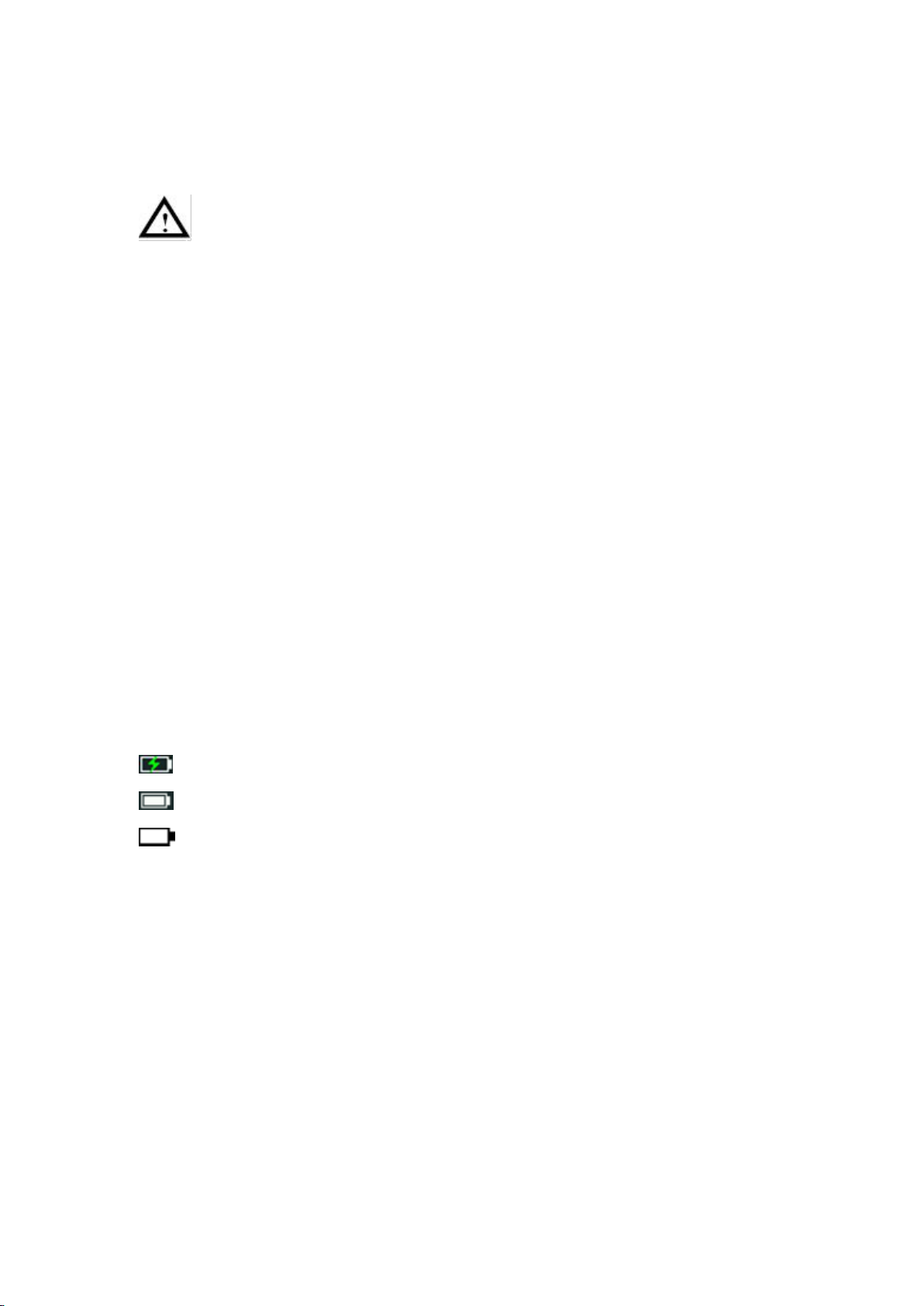
The power supply and battery indicator symbols in the upper right corner of
the screen are explained as follows:
symbol indicates the power-on charging status;
symbol indicates battery power supply;
symbol indicates that there is only about five minutes of use time left.
Please charge as soon as possible according to the relevant tips to avoid
damage to the battery.
Charging Method
Charging the battery through the power adapter: Connect the oscilloscope to
the power socket through the USB data cable and power adapter delivered
with the machine for charging.
Charge the oscilloscope through the USB interface: Connect the oscilloscope
to a computer or other equipment through a USB data cable for charging (pay
attention to the load capacity of the power supply equipment to avoid
Page 44

39
abnormal operation of the equipment).
Note
To avoid overheating of the battery during charging, the ambient temperature
must not exceed the allowable value given in the technical specifications.
Replacement of Lithium Battery
Generally, the battery does not need to be replaced. However, when
necessary, it can only be replaced by qualified personnel, and only lithium
batteries of the same specification can be used.
 Loading...