

Page 1

Dual-Channel Arbitrary
Waveform Generator
AG1012F
AG1022F
AG2052F
AG2062F
User Manual
WWW.OWON.COM.HK
Page 2

Headquarter:
Branch:
Oct. 2014 edition V2.1
Copy Right in this Manual © Lilliput Company. All rights Reserved.
The Lilliput's products are under the protection of the patent rights in America and other countries,
including ones which have already obtained the patent rights and those which are applying for. The
information in this manual will replace all that in the materials published originally.
The information in this manual was correct at the time of printing. However, OWON will continue to
improve products and reserves the rights to changes specification at any time without notice.
OWON is the registered trademark of the Lilliput Company.
19 Heming Road, Lantian industrial zone, Zhangzhou, Fujian, China
Tel: +86-596-2130430 Fax:+86-596-2109272
www.owon.com.hk Mail: Business Consulting: [email protected]
Web:
Fujian Lilliput Optoelectronics Technology Co.,Ltd.: The mansion of optoelectronics,
Sale service: [email protected]
ZhenZhuWan,
Tel: +86-592-2575666 Fax:+86-592-2575669
Xiamen Lilliput Technology Co.,Ltd.: the 5th floor, B Area, Chuangxin Mansion, Software Park,
Huandao RD, Xiamen, Fujian, China
Page 3

General Warranty
Lilliput warrants that the product will be free from defects in materials and workmanship
for a period of 3 years (1 year for accessories) from the date of purchase of the product
by the original purchaser from the Lilliput Company. This warranty only applies to the
original purchaser and is not transferable to the third party. If the product proves
defective during the warranty period, Lilliput either will repair the defective product
without charge for parts and labor, or will provide a replacement in exchange for the
defective product. Parts, modules and replacement products used by Lilliput for warranty
work may be new or reconditioned to like new performance. All replaced parts, modules
and products become the property of Lilliput.
In order to obtain service under this warranty, Customer must notify Lilliput of the defect
before the expiration of the warranty period. Customer shall be responsible for
packaging and shipping the defective product to the service center designated by Lilliput,
and with a copy of customer proof of purchase.
This warranty shall not apply to any defect, failure or damage caused by improper use or
improper or inadequate maintenance and care. Lilliput shall not be obligated to furnish
service under this warranty a) to repair damage resulting from attempts by personnel
other than Lilliput representatives to install, repair or service the product; b) to repair
damage resulting from improper use or connection to incompatible equipment; c) to
repair any damage or malfunction caused by the use of non-Lilliput supplies; or d) to
service a product that has been modified or integrated with other products when the
effect of such modification or integration increases the time or difficulty of servicing the
product.
Please contact the nearest Lilliput's Sales and Service Offices for services or a complete
copy of the warranty statement.
For better after-sales service, please visit www.owon.com.hk and register the purchased
product online.
Excepting the after-sales services provided in this summary or the applicable warranty statements,
Lilliput will not offer any guarantee for maintenance definitely declared or hinted, including but not
limited to the implied guarantee for marketability and special-purpose acceptability. Lilliput should
not take any responsibilities for any indirect, special or consequent damages.
Page 4

i
Table of Contents
1.General Safety Requirements ..................................................................................... 1
2.Safety Terms and Symbols ......................................................................................... 2
3.General Characteristics ............................................................................................. 3
4.Quick Start ................................................................................................................ 4
Front/Rear Panel and User Interface ................................................................................... 5
Front Panel ............................................................................................................................................... 5
Rear Panel ................................................................................................................................................ 6
User Interface ........................................................................................................................................... 7
General Inspection .............................................................................................................. 8
Foot Stool Adjustment ........................................................................................................ 8
Power-On Check ................................................................................................................. 9
AC Power Input Setting ............................................................................................................................ 9
Power On .................................................................................................................................................. 9
5.Front Panel Operation ............................................................................................ 10
To set channels .................................................................................................................. 11
To set signals ..................................................................................................................... 12
To Output Sine Signals ............................................................................................................................ 12
To Set the Frequency/Period ............................................................................................................................... 12
To Set the Amplitude ........................................................................................................................................... 13
To Set the Offset .................................................................................................................................................. 13
To Set the High Level ............................................................................................................................................ 13
To Set the Low Level ............................................................................................................................................ 13
To Output Square Signals ....................................................................................................................... 13
To Set the Duty Cycle ........................................................................................................................................... 14
To Output Ramp Signals ......................................................................................................................... 15
To Set the Symmetry ............................................................................................................................................ 15
To Output Pulse Signals .......................................................................................................................... 16
To Set the Pulse Width / Duty Cycle .................................................................................................................... 17
To Output Noise Signals ......................................................................................................................... 17
To Output Arbitrary Signals .................................................................................................................... 18
To Select the Built-in Waveform........................................................................................................................... 19
The User-Definable Waveform ............................................................................................................................. 20
To Output DC .......................................................................................................................................... 22
To recall wave file ................................................................................................................................... 22
Use SDS Series oscilloscope manufactured by OWON to cut wave: .................................................................... 22
Use waveform generators to recall wave: ............................................................................................................ 23
To Generate the Modulated Waveform .............................................................................. 24
Page 5

ii
AM (Amplitude Modulation) .................................................................................................................. 25
FM (Frequency Modulation) .................................................................................................................. 26
PM (Phase Modulation) .......................................................................................................................... 27
FSK (Frequency Shift Keying) .................................................................................................................. 28
PWM (Pulse Width Modulation) (only in AG2052F and AG2062F) ........................................................ 29
To Generate Sweep ............................................................................................................ 29
To Generate Burst .............................................................................................................. 31
Set the N-Cycle Burst .............................................................................................................................. 31
Set the Gated Burst ................................................................................................................................ 32
To Save and Recall ............................................................................................................. 33
To Use USB Storage ................................................................................................................................ 33
To Edit the File Name ............................................................................................................................. 33
To Set the Utility Function .................................................................................................. 34
To Set Display Parameter ....................................................................................................................... 34
To Set the Bright .................................................................................................................................................. 34
To Set the Separator ............................................................................................................................................ 34
To Set the Screen Saver ........................................................................................................................................ 34
To Set the Counter ................................................................................................................................. 35
To Set Output Parameter ....................................................................................................................... 35
To Set the Output Load ........................................................................................................................................ 35
To Set the Phase Deviation .................................................................................................................................. 36
To Set the System ................................................................................................................................... 36
Language Setting.................................................................................................................................................. 36
Power On Setting ................................................................................................................................................. 36
To Return to Default Setting................................................................................................................................. 36
To Set the Beep .................................................................................................................................................... 38
View System Information .................................................................................................................................... 38
To Set the Clock Source ........................................................................................................................................ 38
To Use Built-in Help ........................................................................................................... 38
6.Communication with PC ......................................................................................... 39
7.SCPI ....................................................................................................................... 40
8.Troubleshooting ...................................................................................................... 40
9.Technical Specifications .......................................................................................... 41
10.Appendix ............................................................................................................... 47
Appendix A: Enclosure ....................................................................................................... 47
Appendix B: General Care and Cleaning .............................................................................. 47
Page 6

1.General Safety Requirements
1
1. General Safety Requirements
Before any operations, please read the following safety precautions to avoid any
possible bodily injury and prevent this product or any other products connected from
damage. In order to avoid any contingent danger, this product is only used within the
range specified.
Check AC power input setting according to the standards in your own country (see page 9,
AC Power Input Setting).
Only the qualified technicians can implement the maintenance.
To avoid Fire or Personal Injury:
Use Proper Power Cord. Use only the power cord supplied with the product and
certified to use in your country.
Product Grounded. This instrument is grounded through the power cord grounding
conductor. To avoid electric shock, the grounding conductor must be grounded. The
product must be grounded properly before any connection with its input or output
terminal.
Check all Terminal Ratings. To avoid fire or shock hazard, check all ratings and
markers of this product. Refer to the user's manual for more information about
ratings before connecting to the instrument.
Do not operate without covers. Do not operate the instrument with covers or panels
removed.
Use Proper Fuse. Use only the specified type and rating fuse for this instrument.
Avoid exposed circuit. Do not touch exposed junctions and components when the
instrument is powered.
Do not operate if in any doubt. If you suspect damage occurs to the instrument,
have it inspected by qualified service personnel before further operations.
Use your instrument in a well-ventilated area. Make sure the instrument installed
with proper ventilation, refer to the user manual for more details.
Do not operate in wet conditions.
Do not operate in an explosive atmosphere.
Keep product surfaces clean and dry.
Page 7

2.Safety Terms and Symbols
2
2. Safety Terms and Symbols
Safety Terms
Terms in this Manual. The following terms may appear in this manual:
Warning: Warning indicates the conditions or practices that could result in
injury or loss of life.
Caution: Caution indicates the conditions or practices that could result in
damage to this product or other property.
Terms on the Product. The following terms may appear on this product:
Danger: It indicates an injury or hazard may immediately happen.
Warning: It indicates an injury or hazard may be accessible potentially.
Caution: It indicates a potential damage to the instrument or other property might occur.
Safety Symbols
Symbols on the Product. The following symbol may appear on the product:
Hazardous Voltage
Protective Earth Terminal
Test Ground
Refer to Manual
Chassis Ground
Page 8

3.General Characteristics
3
3. General Characteristics
These products are dual-channel multi-function generator which combines Arbitrary
Waveform Generation and Function Generation. The product introduces Direct Digital
Synthesizer (DDS) technology to provide stable, precise, pure and low distortion signal.
The user-friendly interface design and panel layout bring exceptional user experience.
Support USB storage device. Provide more alternative solutions for users.
Features and benefits:
3.9 inch high resolution (480 × 320 pixels) TFT LCD display;
Advanced DDS technology, max. 60 MHz frequency output;
Max. Sample rate: 250 MSa/s, Frequency resolution: 1 μHz;
Vertical resolution: 14 bits, max. 1 M waveform record length;
Abundant waveform output: 5 basic waveforms and 45 built-in arbitrary waveforms
output;
Exponential rise, Exponential fall, Sin(x)/x, Staircase, etc. 45 built-in waveforms and
user defined arbitrary waveform;
Abundant modulation functions along with output liner/logarithm sweep and pulse
string waveform;
Standard interface: USB port, USB (type B) connector.
Page 9

4.Quick Start
4
4. Quick Start
This chapter will deal with the following topics mainly:
Front/Rear Panel Overview
User Interface Overview
How to Implement General Inspection
How to Adjust the Foot Stools
How to Implement Power-On Check
Page 10

4.Quick Start
5
①
②
③
④
⑥
⑱
⑬
⑮
⑭
⑯
⑲
⑩
⑪
⑦
⑧
⑨
⑫
⑤
⑰
LCD
Display the user interface
Menu selection
buttons
sign
Knob
Change the current highlighted number, also can be used to
select file location or switch the character of the soft
Cycle Burst, if you choose Source as
Copy menu.
Direction key
Move the cursor of the focused parameter or select the file
locations
Save button
Store/recall the user-defined arbitrary waveform data or
instrument state
Utility button
Set the auxiliary system function.
Help button
View the build-in help information
Front/Rear Panel and User Interface
Front Panel
Figure 4-1 Front panel overview (AG1022F shown)
①
②
Number keys Input parameters, include: number, point and plus/minus
③
④
⑤
Include 5 buttons: F1 - F5, activate the corresponding menu
keyboard when entering file name.
In Sweep and N"Manual", every time you press this knob, the generator will
be triggered once.
In signal output interface, press this knob to enter Channel
⑥
⑦
⑧
Page 11

4.Quick Start
6
will be lighted
when CH2 is tuned on.
CH2 Output
Output signal of CH2
Foot stool
Make the instrument to be tilted for ease of operation
will be lighted
when CH1 is tuned on.
CH1 Output
Output signal of CH1
Switch channel displayed on the screen between CH1 and
CH2.
Modulation (Mod)
Generate the Modulated waveforms, Sweep and Burst; these
functions are only used for CH1.
Both button
function is enabled, the backlight of the button turns on.
USB port
Connect with an external USB device, such as connect a USB
device to the instrument.
Waveform selection
waveform is selected, the backlight of the button turns on.
Power button
Turn on/off the generator
①
⑤
④
③
②
⑥⑦
⑧
CH2 Output Control Turn on/off the output of CH2. The backlight
⑨
⑩
⑪
CH1 Output Control Turn on/off the output of CH1. The backlight
⑫
⑬
C H 1/2 button
⑭
⑮
⑯
⑰
⑱
buttons
⑲
Rear Panel
Display the editable parameters of both channels. When the
Include: Sine , Square , Ramp , Pulse ,
Noise and Arbitrary waveform. When a
Figure 4-2 Rear panel overview
Page 12

4.Quick Start
7
Power socket
AC input connector
Fuse
Use the specified fuse according to the voltage scale.
Power switch
Switch between 110 V and 220 V.
This can be used to connect a USB type B controller.
and controlled via PC software.
Ext Mod In
Connector
Ext Trig/Burst/Fsk
In connector
This signal can be used as external signal source in Sweep,
Burst and FSK mode.
Ref Clk/Counter In
connector
To accept an external clock signal, or to accept the input
signal of counter. (See page 38, To S e t t he Counter)
Clock Source)
④
⑨
⑧
③
⑦
②
①
⑥
⑤
⑩
⑪
Current channel
②
Parameter 1, display parameter and edit the focused parameter
③
Current signal type or mode
④
The setting menu of current signal or mode
①
②
③
USB (type B)
④
connector
⑤
⑥
⑦
Ref Clk Out
⑧
connector
User Interface
Connect with an external device, such as connected to a PC
External modulation input, use it as external signal source.
To synchronize generators. Output a clock signal generated
by the crystal inside the generator. (See page 38, To Set the
Figure 4-3 User interface (take Sine for instance)
①
Page 13

4.Quick Start
8
⑤
Parameter 3, display parameter and edit the focused parameter
⑥
Parameter 2, display parameter and edit the focused parameter
⑦
Display current waveform
⑧
Offset/low level, depends on the highlighted menu item on the right
⑨
Amplitude/high level, depends on the highlighted menu item on the right
⑩
Frequency/period, depends on the highlighted menu item on the right
⑪
Load, High Z represents high resistance
General Inspection
After you get a new Waveform Generator, it is recommended that you should make a
check on the instrument according to the following steps:
1. Check whether there is any damage caused by transportation.
If it is found that the packaging carton or the foamed plastic protection cushion has
suffered serious damage, do not throw it away first till the complete device and its
accessories succeed in the electrical and mechanical property tests.
2. Check the Accessories
The supplied accessories have been already described in the Appendix A: Enclosure
of this Manual. You can check whether there is any loss of accessories with reference
to this description. If it is found that there is any accessory lost or damaged, please
get in touch with the distributor of Lilliput responsible for this service or the Lilliput's
local offices.
3. Check the Complete Instrument
If it is found that there is damage to the appearance of the instrument, or the
instrument can not work normally, or fails in the performance test, please get in
touch with the Lilliput's distributor responsible for this business or the Lilliput's local
offices. If there is damage to the instrument caused by the transportation, please
keep the package. With the transportation department or the Lilliput's distributor
responsible for this business informed about it, a repairing or replacement of the
instrument will be arranged by the Lilliput.
Foot Stool Adjustment
Unfold the foot stools on the bottom of the generator, as ⑪ in Figure 4-1.
Page 14

4.Quick Start
9
110 V
125 V, F4AL
220 V
250 V, F2AL
Power-On Check
AC Power Input Setting
Adopt 100 - 110 VAC or 220 - 230 VAC power source. Users should regulate the voltage
scale of the Power Switch according to the standards in their own country (see Figure 4-2)
at the rear panel and use an appropriate fuse.
Voltage Fuse
To change the voltage scale of the instrument, do the following steps:
(1) Turn off the power button at the front panel and remove the power cord.
(2) Check if the fuse installed before leaving factory (250 V, F2AL) can match with the
selected voltage scale; if not, pry the cover open using a straight screwdriver (see ②
in Figure 4-2), change the fuse.
(3) Regulate the Power Switch to the desired voltage scale.
Power On
(1) Connect the instrument to the AC supply using the supplied power cord.
Warning:
To avoid electric shock, the instrument must be grounded properly.
(2) Press down the power button at the front panel, the screen shows the boot screen.
Page 15

5.Front Panel Operation
10
5. Front Panel Operation
This chapter will deal with the following topics mainly:
How to Set Channels
How to Output Sine Signals
How to Output Square Signals
How to Output Ramp Signals
How to Output Pulse Signals
How to Output Noise Signals
How to Output Arbitrary Signals
How to Output DC
How to Generate the Modulated Waveform
How to Generate Sweep
How to Generate Burst
How to Save and Recall
How to Set the Utility Function
How to Use Built-in Help
Page 16

5.Front Panel Operation
11
CH1
Waveform
Parameter 1
Parameter 4
CH2
Waveform
Parameter 1
Parameter
2
Parameter 3
Parameter 2
Parameter 3
To set channels
To Switch Channels for Display
Press CH1/2 button to switch channel displayed on the screen between CH1 and CH2.
To Display/Edit Both Channels
Press Both button to display the parameters of both channels.
To switch channel: Press CH1/2 to switch the editable channel.
To select waveform: Press Waveform selection buttons to select waveform of current
channel.
To select parameter: Press F2 - F5 to choose the Parameter 1 to Parameter 4;
Press it again to switch the current parameter such as Frequency/Period.
To edit parameter: Turn the knob to change the value of cursor position. Press /
direction key to move the cursor. (The number keys can not be used to input.)
Figure 5-1: The User Inter face of Both button
To Turn On/Off Output of Channels
Press CH1 or CH2 to turn on/off output of the corresponding channel. The indicator will
be lighted when the corresponding channel is tuned on.
Channel Copy
(1) In signal output interface, press the knob on the front panel to enter Channel Copy
menu.
(2) Press F1 to select From CH2 To CH1, or press F2 to select From CH1 To CH2.
Page 17
5.Front Panel Operation
12
Channel
Setting menu
of Sine signal
Amplitude
Load
Offset
Current signal
Frequency
Parameter 3
Parameter 2
Parameter 1
Sine
To set signals
The following describes how to set and output Sine, Square, Ramp, Pulse, Noise, Arbitrary,
DC signals and copy channle.
To Output Sine Signals
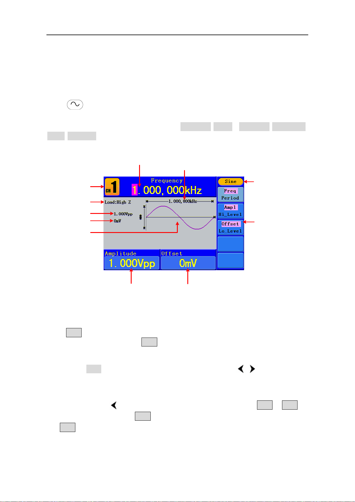
Press button to call the user interface of Sine signal, the Sine waveform
parameters can be set by operating the Sine setting menu on the right.
The parameters of Sine waveform are: Frequency/Period, Amplitude/High Level,
Offset/Low Level. You can operate the menu by using the menu selection buttons on the
right.
Figure 5-2: The User I nt erface of Sine Signal
To Set the Frequency/Period
Press F1 button, the chosen menu item is highlighted, the focused parameter is
displayed in Parameter 1. Press F1 button to switch between Frequency/Period.
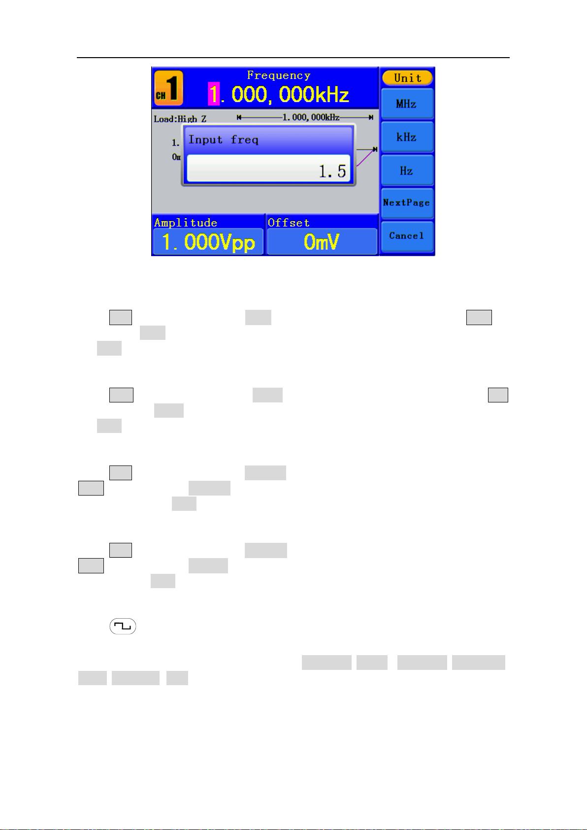
Two methods to change the chosen parameter:
Turn the knob to change the value of cursor position. Press / direction key to
Press a number key in the front panel, an input box will pop up; keep going to input
move the cursor.
the value. Press direction key to delete the last number. Press F1 - F3 to
choose the unit, or press F4 to go to next page and choose other units. Press
F5 to cancel the input.
Page 18
5.Front Panel Operation
13
Figure 5-3: Set the frequency using number keys
To Set the Amplitude
Press F2 , confirm whether the "Ampl" menu item is highlighted; if not, press F2 to
switch into "Ampl". In Parameter 2, a cursor appears under the value of amplitude. Use
the knob or the number keys to set the desired value.
To Set the Offset
Press F3 , confirm whether the "Offset" menu item is highlighted; if not, press F3
to switch into "Offset". In Parameter 3, a cursor appears under the value of offset. Use
the knob or the number keys to set the desired value.
To Set the High Level
Press F2 , confirm whether the "Hi_Level" menu item is highlighted; if not, press
F2 to switch into "Hi_Level". In Parameter 2, a cursor appears under the value of
amplitude. Use the knob or the number keys to set the desired value.
To Set the Low Level
Press F3 , confirm whether the "Lo_Level" menu item is highlighted; if not, press
F3 to switch into "Lo_Level". In Parameter 3, a cursor appears under the value of
offset. Use the knob or the number keys to set the desired value.
To Output Square Signals
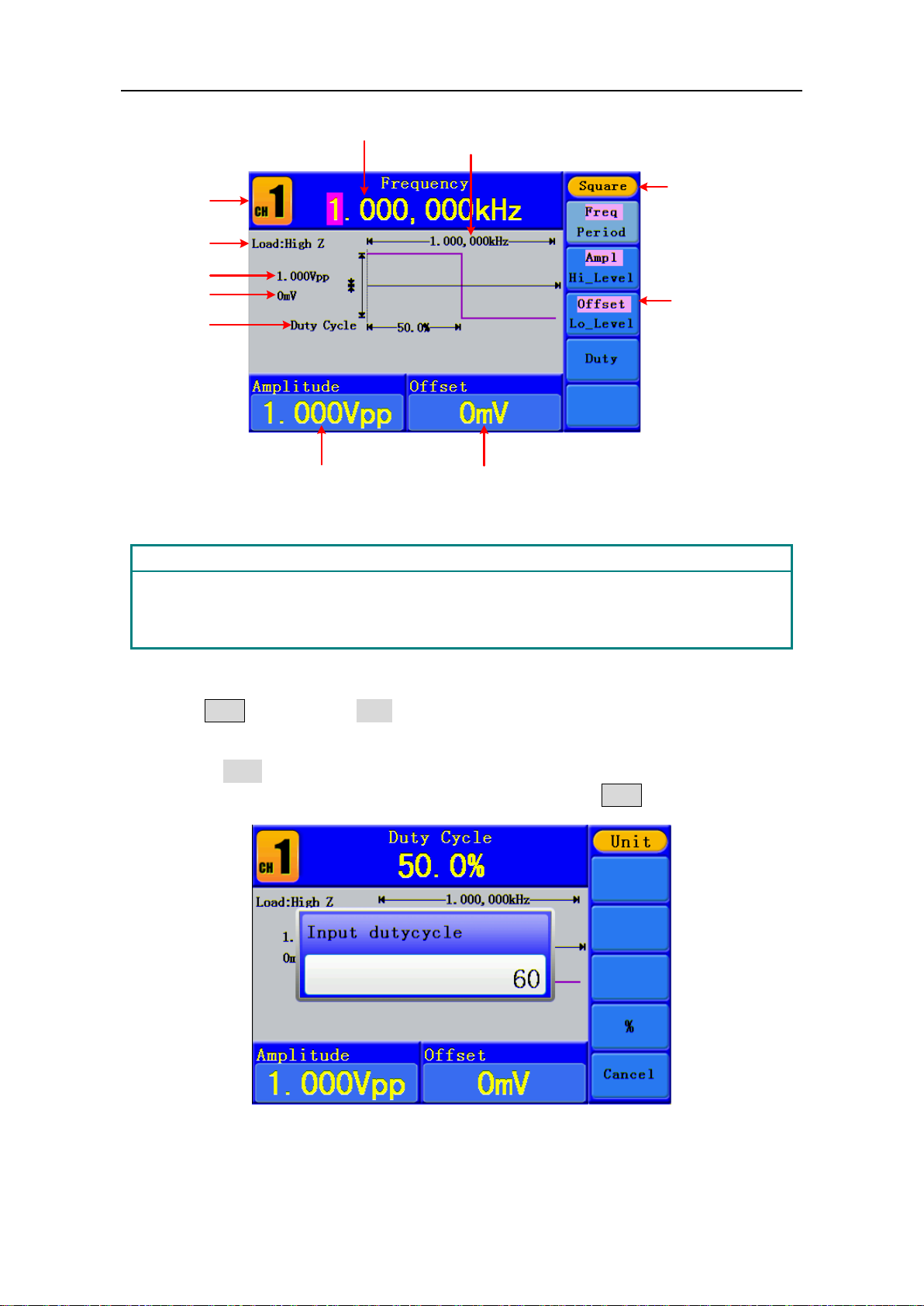
Press button to call the user interface of Square signal, the Square waveform
parameters can be set by operating the Square setting menu on the right.
The parameters of Square waveform are: Frequency/Period, Amplitude/High Level,
Offset/Low Level, Duty. You can operate the menu by using the menu selection buttons
on the right.
To set the Frequency/Period, Amplitude/High Level, Offset/Low Level, please refer to To
Output Sine Signals on page 12.
Page 19
5.Front Panel Operation
14
Channel
Setting menu of
Square signal
Amplitude
Load
Offset
Current signal
Frequency
Parameter
1
Duty cycle
Parameter 2
Parameter
3
Term Explanation
Duty Cycle:
The percentage that the High Level takes up the whole Period.
Figure 5-4: The User Inter face of Square Signal
To Set the Duty Cycle
(1) Press F4 button, the "Duty" menu item is highlighted, the current value of the
Duty cycle is displayed in Parameter 1.
(2) Turn the knob to change the value directly;
or press the number keys to input the desired value, press F4 to choose "%".
Figure 5-5: Set the Duty cycle of Square signal
Page 20
5.Front Panel Operation
15
Channel
Setting menu
of Ramp signal
Amplitude
Load
Offset
Current signal
Frequency
Parameter 1
Symmetry
Parameter 2
Parameter 3
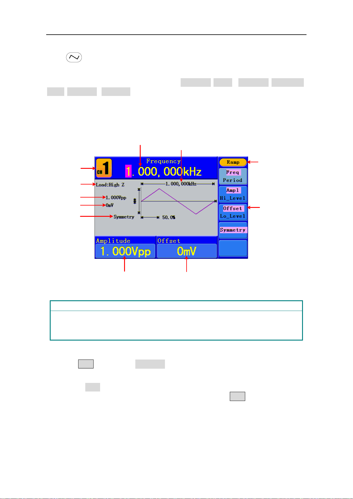
Term Explanation
The percentage that the Rising Period takes up the whole Period.
To Output Ramp Signals
Press button to call the user interface of Ramp signal, the Ramp waveform
parameters can be set by operating the Ramp setting menu on the right.
The parameters of Ramp waveform are: Frequency/Period, Amplitude/High Level,
Offset/Low Level, Symmetry. You can operate the menu by using the menu selection
buttons on the right.
To set the Frequency/Period, Amplitude/High Level, Offset/Low Level, please refer to To
Output Sine Signals on page 12.
Figure 5-6: The User Inter face of Ramp Signal
Symmetry:
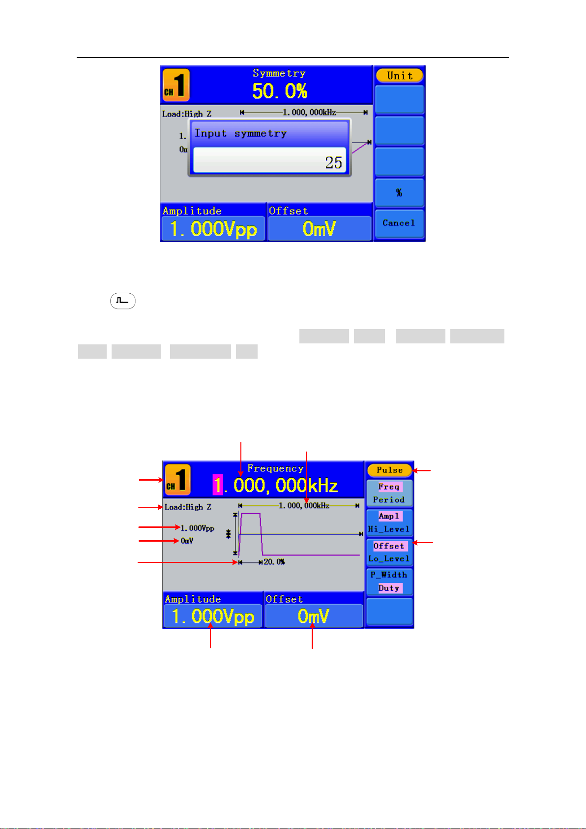
To Set the Symmetry
(1) Press F4 button, the "Symmetry" menu item is highlighted, the current value of
(2) Turn the knob to change the value directly;
the symmetry is displayed in Parameter 1.
or press the number keys to input the desired value, press F4 to choose "%".
Page 21
5.Front Panel Operation
16
Channel
Setting menu
of Pulse signal
Amplitude
Load
Offset
Current signal
Frequency
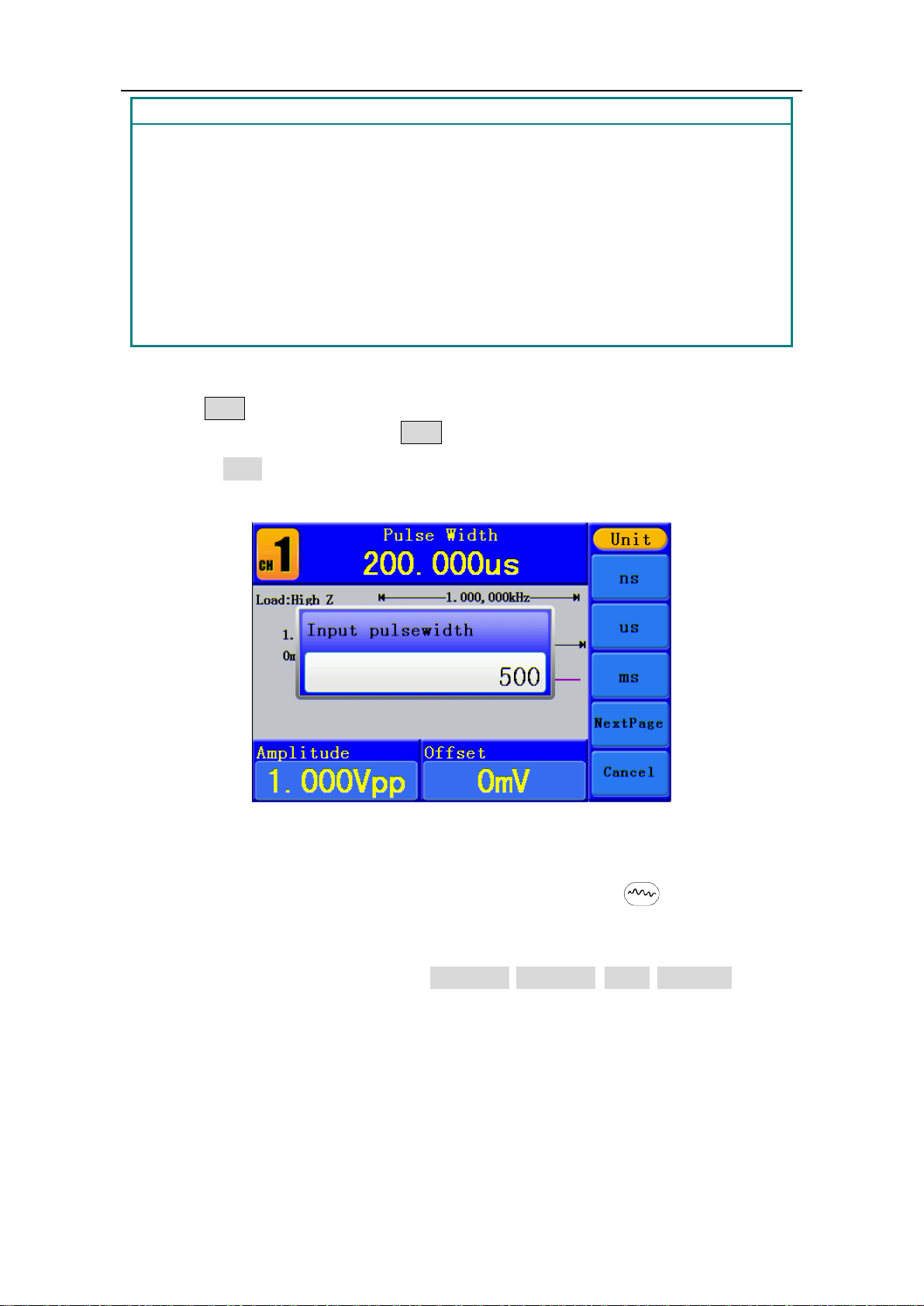
Pulse width
Parameter 2
Parameter 3
Parameter 1
Figure 5-7: Set the symmetry of Ramp signal
To Output Pulse Signals
Press button to call the user interface of Pulse signal, the Pulse waveform
parameters can be set by operating the Pulse setting menu on the right.
The parameters of Pulse waveform are: Frequency/Period, Amplitude/High Level,
Offset/Low Level, Pulse Width/Duty. You can operate the menu by using the menu
selection buttons on the right.
To set the Frequency/Period, Amplitude/High Level, Offset/Low Level, please refer to To
Output Sine Signals on page 12.
Figure 5-8: The User Inter face of Pulse Signal
Page 22
5.Front Panel Operation
17
Term Explanation
the time span between thresholds of 50% of the rising edge
me span between thresholds of 50% of the falling edge
the formula is: Pulse Width = Period * Duty Cycle.
Pulse Width:
There are two kinds of Pulse Width—positive and negative.
Positive Pulse Width is
amplitude to the next 50% of the falling edge amplitude.
Negative Pulse Width is the ti
amplitude to the next 50% of the rising edge amplitude.
Pulse Width is determined by Period and Duty Cycle;
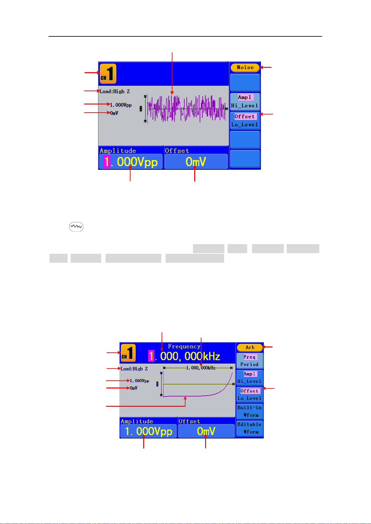
To Set the Pulse Width / Duty Cycle
(1) Press F4 button, the chosen menu item is highlighted, the focused parameter is
displayed in Parameter 1. Press F4 to switch between Pulse Width/Duty.
(2) Turn the knob to change the value directly;
or press the number keys to input the desired value and choose the unit.
Figure 5-9: Set the Pulse Wid th of Pulse signal
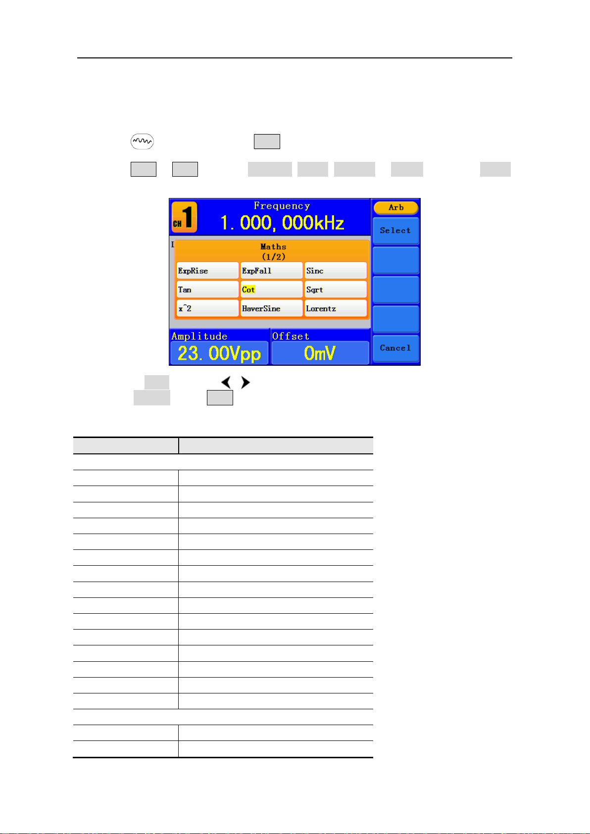
To Output Noise Signals
The noise signal which the generator output is white noise. Press button to call the
user interface of Noise signal, the Noise waveform parameters can be set by operating
the Noise setting menu on the right.
The parameters of Noise waveform are: Amplitude/High Level, Offset/Low Level. Yo u can
operate the menu by using the menu selection buttons on the right.
To set the Amplitude/High Level, Offset/Low Level, please refer to To Output Sine Signals
on page 12.
Page 23
5.Front Panel Operation
18
Setting menu
of Noise signal
Amplitude
Load
Offset
Current signal
Channel
Parameter 2
Parameter 3
Noise waveform
Channel
Setting menu of
Arbitrary signal
Amplitude
Load
Offset
Current signal
Frequency
Parameter 1
Parameter 2
Parameter 3
Built-in Exponential
Rise Waveform
Figure 5-10: The User Interface of Noise Signal
To Output Arbitrary Signals
Press button to call the user interface of Arbitrary signal, the Arbitrary waveform
parameters can be set by operating the Arbitrary setting menu on the right.
The menu items of Arbitrary waveform are: Frequency/Period, Amplitude/High Level,
Offset/Low Level, Built-in Waveform, Editable Waveform. You can operate the menu by
using the menu selection buttons on the right.
To set the Frequency/Period, Amplitude/High Level, Offset/Low Level, please refer to To
Output Sine Signals on page 12.
The Arbitrary signal consists of two types: the system built-in waveform and the
user-definable waveform.
Figure 5-11: The User Interface of Arbitrary Signal
Page 24
5.Front Panel Operation
19
Name
Explanation
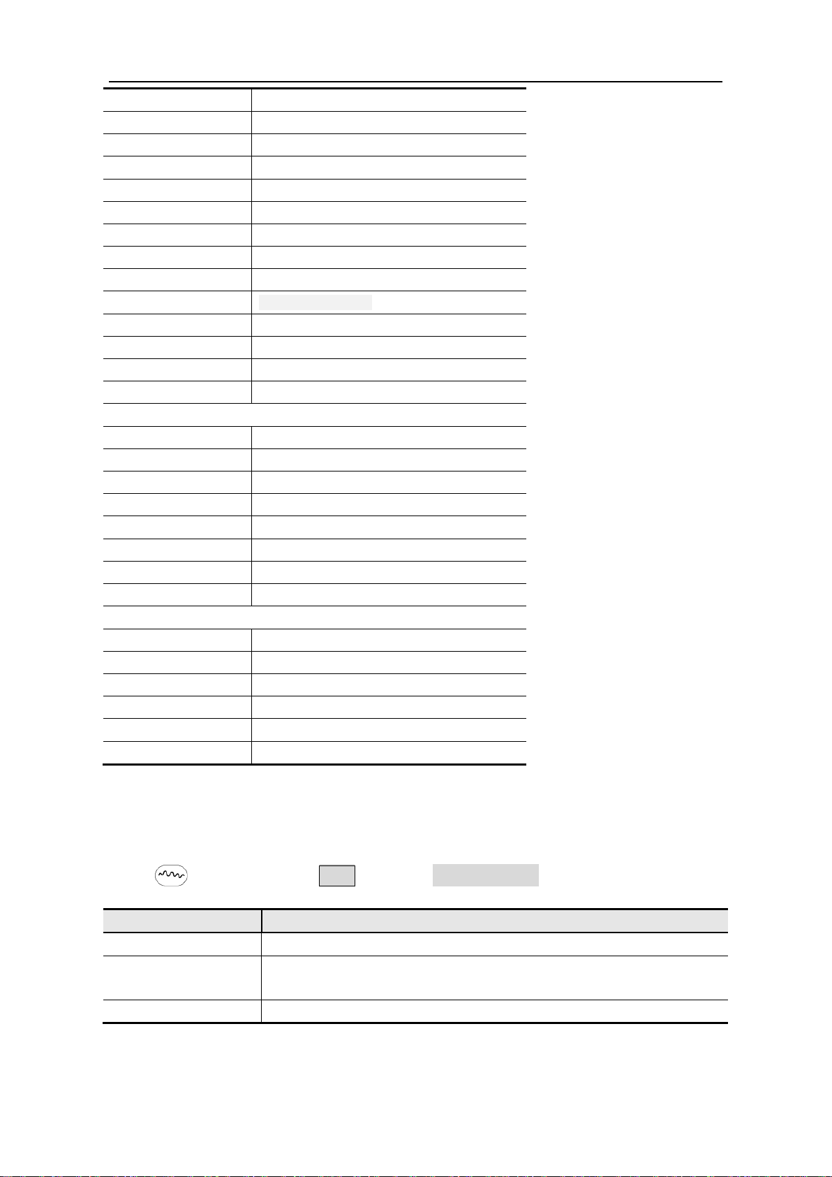
To Select the Built-in Waveform
There are 45 built-in Arbitrary waveforms.
Steps for selecting the built-in waveform:
(1) Press button, then press F4 to enter the Built-in Wform menu.
(2) Press F1 - F4 to select Common, Maths, Window or Others. E.g. select Maths
to enter the following interface.
(3) Turn the knob or press / direction key to choose the desired waveform. E.g.
select ExpRise. Press F1 to output the Exponential Rise waveform.
Built-in Wavefor m Table
Common
StairD Stair-down waveform
StairU Stair-up waveform
StairUD Stair-up and stair-down waveform
Trapezia Trapezoid waveform
RoundHalf RoundHalf wave
AbsSine Absolute value of a Sine
AbsSineHalf Absolute value of half a Sine
SineTra Sine transverse cut
SineVer Sine vertical cut
NegRamp Negative ramp
AttALT Gain oscillation curve
AmpALT Attenuation oscillation curve
CPulse Coded pulse
PPulse Positive pulse
NPulse Negative pulse
Maths
ExpRise Exponential rise function
ExpFall Exponential fall function
Page 25
5.Front Panel Operation
20
Windows
Others
Menu item
Instruction
Create Wform
Create a new waveform.
Select the waveform stored in internal storage (FLASH) or USB
device (USBDEVICE).
Edit Wform
Edit the stored waveform.
Sinc Sinc function
Tan Tangent
Cot Cotangent
Sqrt Square root
XX Square function
HaverSine HaverSine function
Lorentz Lorentz function
ln Natural logarithm function
Cubic Cubic function
Cauchy Cauchy distribution
Besselj BesselI function
Bessely BesselII function
Erf Error function
Airy Airy function
Rectangle Rectangle window
Gauss Gauss distribution
Hamming Hamming window
Hann Hanning window
Bartlett Bartlett window
Blackman Blackman window
Laylight Laylight window
Triang Triangle window (Fejer window)
DC DC signal
Heart Heart signal
Round Round signal
LFMPulse Linear FM pulse
Rhombus Rhombus signal
Cardiac Cardiac signal
The User-Definable Waveform
Press button and press F5 to select "Editable Wform".
Select Wform
Page 26

5.Front Panel Operation
21
How to Create a New Waveform
(1) Enter the operation menu: Press →Editable Wform →Create Wform.
(2) Set the number of waveform points: Press F1 to select "Wform Points", turn the
knob or press the number keys to input the desired value and choose the unit. X1, XK,
XM respectively represent 1, 1000, 1000,000. The waveform points range is 2 1000,000.
(3) Set the interpolation: Press F2 to switch between On/Off. If you choose On, the
points will be connected with beelines; otherwise, the voltages between two
consecutive points will not change, and the waveform looks like a step-up one.
(4) Edit the waveform points: Press F3 to enter the operation menu.
Press F1 to choose "Points", input the number of the point to be edited.
Press F2 to choose "Voltage", input the voltage for the current point.
Repeat the step above, set all the points to your needs.
Press F4 to choose "Store", enter the file system. If a USB device is
connected, press / direction key to select the storage. "USBDEVICE" is
the USB device storage, "FLASH" is the internal storage. Choose Next level, enter
the desired storage path, choose Save, an input keyboard pops up, input the file
name, and then choose DONE.
How to Select a Stored Waveform
(1) Enter the operation menu: Press →Editable Wform →Select Wform.
(2) Enter the storage path of the desired waveform file. Turn the knob or press /
direction key to select the desired waveform file.
(3) Choose Recall output.
How to Edit a Stored Waveform
(1) Enter the operation menu: Press →Editable Wform →Edit Wform.
(2) Enter the storage path of the desired waveform file. Turn the knob or press /
direction key to select the desired waveform file.
(3) Choose Recall suppress.
How to Delete a Stored Waveform
(1) Press Save function button to enter the file system.
(2) Enter the storage path of the desired waveform file. Turn the knob or press /
direction key to select the desired waveform file.
(3) Choose Delete.
Page 27
5.Front Panel Operation
22
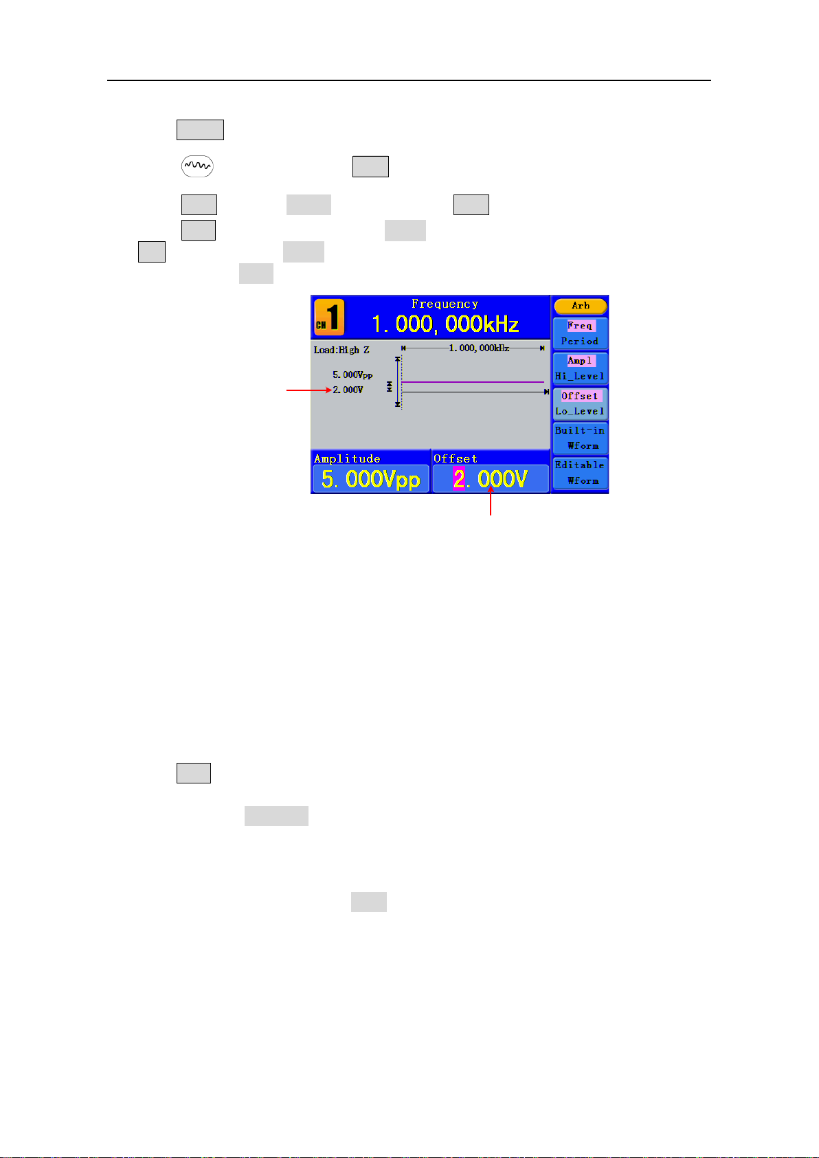
DC Voltage
Parameter 3
To Output DC
(1) Press CH1/2 to select the channel that you want to output DC.
(2) Press button, then press F4 to enter the Built-in Wform menu.
(3) Press F4 to select Others. Select DC. Press F1 to output DC.
(4) Press F3 , confirm whether the "Offset" menu item is highlighted; if not, press
F3 to switch into "Offset". In Parameter 3, a cursor appears under the value of
offset. Use the knob or the number keys to set the desired value and choose the unit.
Figure 5-12: The DC Setting Interface
To recall wave file
This function can read the waveform file with suffix of (*.ota) which is cut from SDS series
oscilloscope manufactured by OWON and saved to USB device or cut by the software of
OWON oscilloscope. Then ARB waveform generators can output the same signal as the
cut wave.
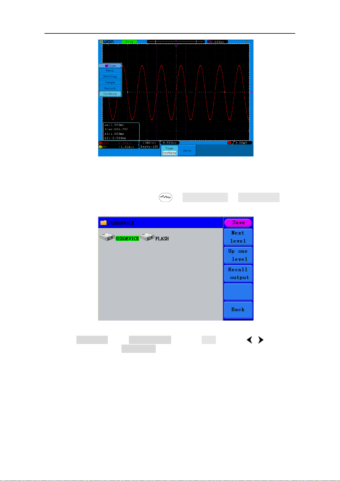
Use SDS Series oscilloscope manufactured by OWON to cut wave:
(1) Connect USB device to SDS series oscilloscope.
(2) Press Save to call out the save menu.
(3) Press the H1 button, the Type menu will display at the left of the screen, turn the M
knob to choose Cut Wave for type.
(4) Move cursor1 and cursor2 to choose the range of wave to be cut.
(5) Press the H2 button, and the input keyboard will pop up. The default name is the
current system date. Turn M knob to choose the keys, and press M knob to input the
chosen keys. Choose and press Enter key of the keyboard to end the input and store
the file with the current name to USB device.
Page 28
5.Front Panel Operation
23
Figure 5-13: Cut Wav e
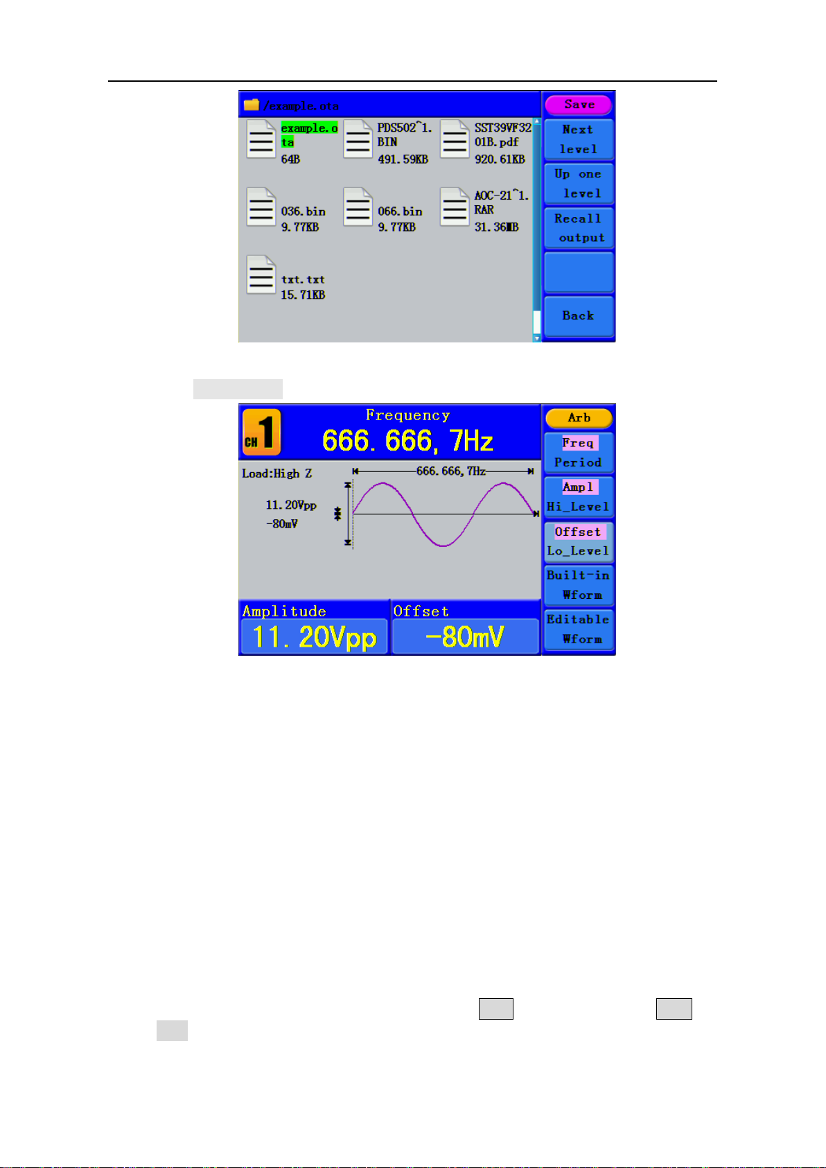
Use waveform generators to recall wave:
(1) Enter the operation menu: Press →Editable Wform →SelectWform. Enter
the following interface:
Figure 5-14: Choose storage device
(2) Select USBDEVICE, enter The Next Level. Turn the knob or press / direction
key to select the saved example.ota waveform file.
Page 29
5.Front Panel Operation
24
Figure 5-15: choose the .ota file
(3) Choose Recall output, and the tip “Read file successfully” will show on the interface.
Figure 5-16: Read file
Tips:
1. Normally the frequency, amplitude, and offset of the recalled wave are the same as the wave
being cut, but when the frequency, amplitude, and offset are set out of the limit range, then the
generator would use the current parameter, which leads to the recalled wave not totally the same
as the cut wave.
2. The max data number of AG1012F AG1022F ARB is 8192. When the wave cut from oscilloscope
contains data number more than 8192, AG1012F and AG1022F will compress data. On the
contrary if the data number is less than 8192, AG1012F and AG1022F will use linear interpolation.
3. The max data number of AG2052F, AG2062F ARB is 1000000. When the wave cut from
oscilloscope contains data number more than 1000000, generators will compress data. On the
contrary if the data number is less than 1000000, generators will use linear interpolation.
To Generate the Modulated Waveform
Modulation function is only used for CH1. Press the Mod button, then press F1 to
select Mod to generate modulated waveform. The waveform generator can modulate
waveform using AM, FM, PM, FSK and PWM (only in AG2052F and AG2062F). To turn off
Page 30
5.Front Panel Operation
25
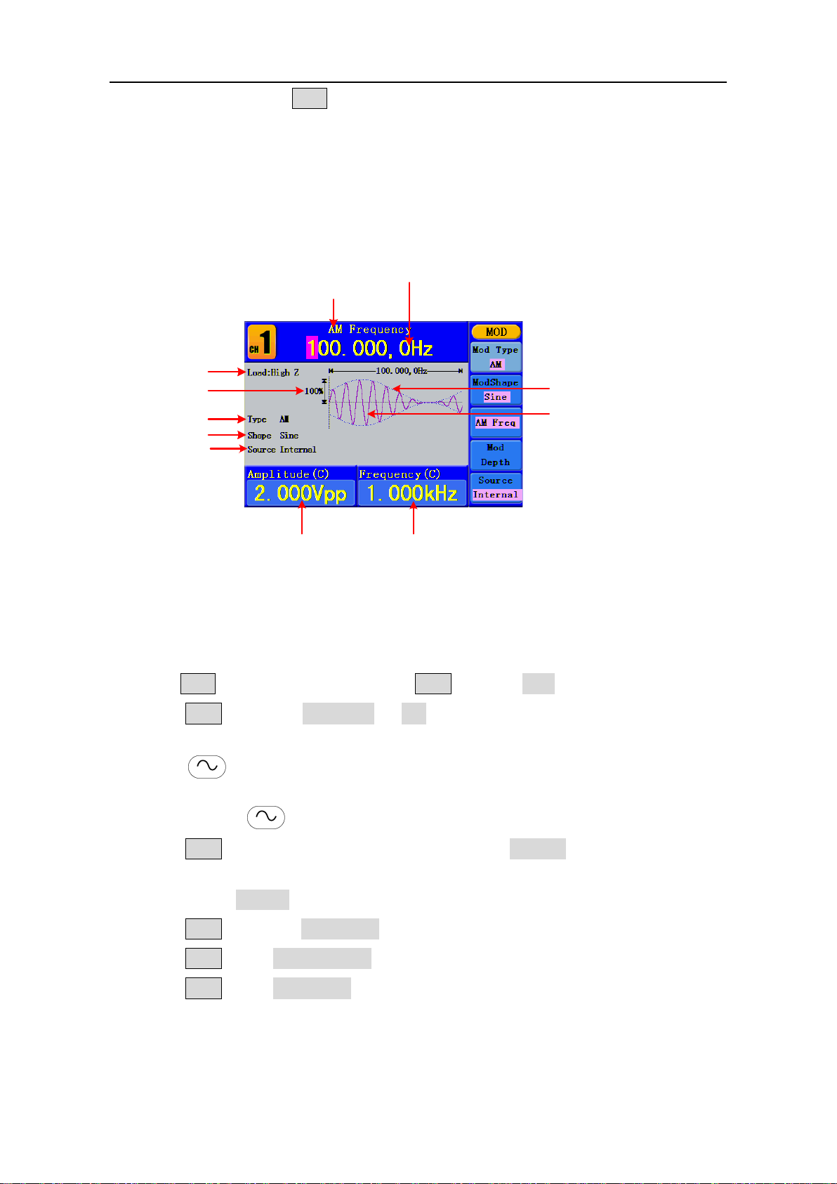
Current Parameter
Carrier
Frequency
Carrier
Amplitude
Carrier Waveform
Modulating Waveform
Load
Mod Depth
AM Frequency
Mod Type
Mod Shape
Source
the modulation, press the Mod button.
AM (Amplitude Modulation)
The modulated waveform consists of two parts: the Carrier Waveform and the
Modulating Waveform. The Carrier Waveform can only be Sine. In AM, the amplitude of
the Carrier Waveform varies with the instantaneous voltage of the modulating waveform.
The user interface of the AM is shown as below.
Figure 5-17: The User Interface of AM
How to set the parameters of AM
(1) Press Mod function button, then press F1 to select Mod.
(2) Press F1 to switch Mod Type to AM. If the Carrier Waveform is not Sine, the
system will switch it to Sine automatically.
(3) Press button to display the waveform and parameters of the Carrier
Waveform. You can change the parameters, please refer to To Output Sine Signals on
page 12. Press button again to return to the Modulation mode interface.
(4) Press F5 to select the source. If the source is External, use the Ext Mod In
connector in the rear panel to input the external signal, the setting of AM is finished.
If you choose Internal, continue to the steps below.
(5) Press F2 to choose Mod Shape, you can choose Sine, Square or Ramp.
(6) Press F3 to set AM Frequency. The range is 2 mHz - 20 kHz (Internal source only).
(7) Press F4 to set Mod Depth. The range is 0% - 100%.
Page 31
5.Front Panel Operation
26
Term Explanation
In the 0% Modulation, the output
Modulation, the output amplitude
panel. +5V corresponds to the currently set depth 100%.
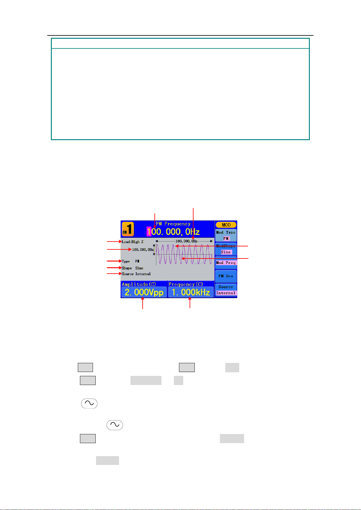
Current Parameter
Carrier
Frequency
Carrier
Amplitude
Carrier Waveform
Modulating Waveform
Load
Frequency Deviation
FM Frequency
Mod Type
Mod Shape
Source
AM Frequency:
The frequency of modulating waveform.
Mod Depth:
The Amplitude Range of modulating waveform.
amplitude is the half of the set one. In the 100%
is the same with the set one. For an external source, the depth of AM is controlled by
the voltage level of the signal connected to the Ext Mod In connector in the rear
FM (Frequency Modulation)
The modulated waveform consists of two parts: the Carrier Waveform and the
Modulating Waveform. The Carrier Waveform can only be Sine. In FM, the frequency of
the Carrier Waveform varies with the instantaneous voltage of the modulating waveform.
The user interface of the FM is shown as below.
Figure 5-18: The User Interface of FM
How to set the parameters of FM
(1) Press Mod function button, then press F1 to select Mod.
(2) Press F1 to switch Mod Type to FM. If the Carrier Waveform is not Sine, the
system will switch it to Sine automatically.
(3) Press button to display the waveform and parameters of the Carrier
Waveform. You can change the parameters, please refer to To Output Sine Signals on
page 12. Press button again to return to the Modulation mode interface.
(4) Press F5 to select the source. If the source is External, use the Ext Mod In
connector in the rear panel to input the external signal, then skip ahead to step (6). If
you choose Internal, continue to the steps below.
Page 32
5.Front Panel Operation
27
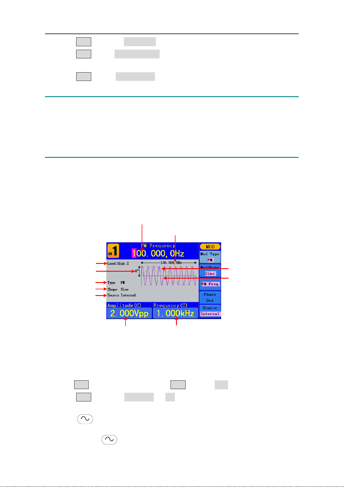
Current Parameter
Carrier
Frequency
Carrier
Amplitude
Carrier Waveform
Modulating Waveform
Load
Phase Deviation
PM Frequency
Mod Type
Mod Shape
Source
(5) Press F2 to choose Mod Shape, you can choose Sine, Square or Ramp.
(6) Press F3 to set Mod Frequency. The range is 2 mHz - 20 kHz (Internal source
only).
(7) Press F4 to set FM Deviation. The Deviation should be less than the Carrier
Waveform Frequency.
Note:
The Sum of the Deviation and the Carrier Frequency should be equal to or less than
maximum frequency of the selected function plus 1 kHz.
For an External Source, the Deviation is controlled by the voltage Level of the signal
connected to the Ext Mod In connector in the rear panel. +5 V corresponds to the selected
Deviation and -5 V to the negative selected Deviation.
PM (Phase Modulation)
The modulated waveform consists of two parts: the Carrier Waveform and the
Modulating Waveform. The Carrier Waveform can only be Sine. In PM, the phase of the
Carrier Waveform varies with the instantaneous voltage level of the modulating
waveform. The user interface of the PM is shown as below.
Figure 5-19: The User Interface of PM
How to set the parameters of PM
(1) Press Mod function button, then press F1 to select Mod.
(2) Press F1 to switch Mod Type to PM. If the Carrier Waveform is not Sine, the
system will switch it to Sine automatically.
(3) Press button to display the waveform and parameters of the Carrier
Waveform. You can change the parameters, please refer to To Output Sine Signals on
page 12. Press button again to return to the Modulation mode interface.
Page 33
5.Front Panel Operation
28
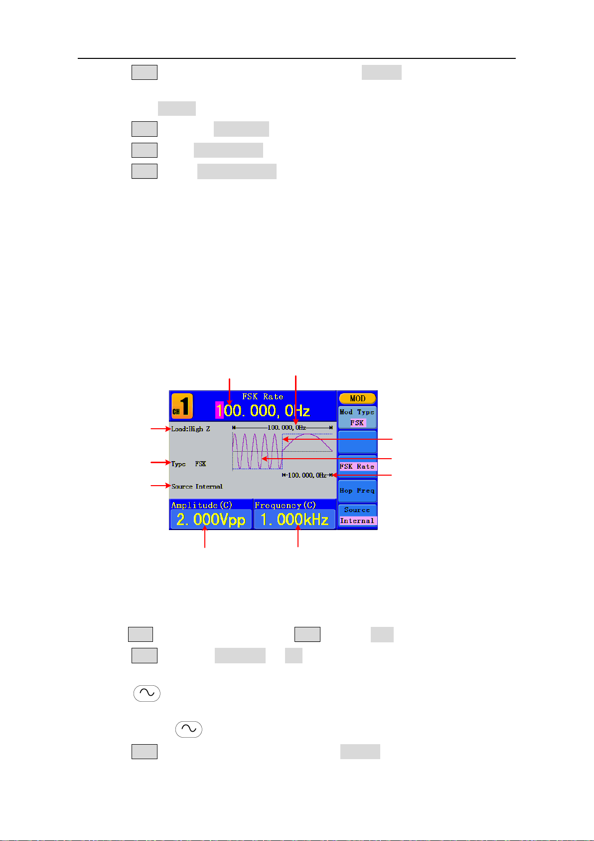
Current Parameter
Carrier Frequency
Carrier Amplitude
Carrier Waveform
Modulating Waveform
Load
FSK Rate
Mod Type
Source
Hop Frequency
(4) Press F5 to select the source. If the source is External, use the Ext Mod In
connector in the rear panel to input the external signal, then skip ahead to step (6). If
you choose Internal, continue to the steps below.
(5) Press F2 to choose Mod Shape, you can choose Sine, Square or Ramp.
(6) Press F3 to set PM Frequency. The range is 2 mHz - 20 kHz (Internal source only).
(7) Press F4 to set Phase Deviation. The Phase Deviation between the Modulating
Waveform and the Carrier Waveform ranging from 0° to 180°.
FSK (Frequency Shift Keying)
The FSK Modulation is a modulation method, the output frequency of which switches
between two the pre-set frequencies (Carrier Waveform Frequency and the Hop
Frequency). The Frequency of the Output Frequency switch between the carrier
waveform frequency and the Hop frequency is called the FSK rate. The frequency by
which the output frequency switch from each other is determined by the Internal
Frequency generator or the Signal Voltage Level offered by the Ext Trig/Burst/Fsk In
connector in the rear panel. The Carrier Waveform can only be Sine. The user interface of
the FSK is shown as below.
Figure 5-20: The User Interface of FSK
How to set the parameters of FSK
(1) Press Mod function button, then press F1 to select Mod.
(2) Press F1 to switch Mod Type to FSK. If the Carrier Waveform is not Sine, the
system will switch it to Sine automatically.
(3) Press button to display the waveform and parameters of the Carrier
Waveform. You can change the parameters, please refer to To Output Sine Signals on
page 12. Press button again to return to the Modulation mode interface.
(4) Press F5 to select the source. If the source is External, use the Ext Trig/Burst/Fsk
In connector in the rear panel to input the external signal, then skip ahead to step (5).
Page 34
5.Front Panel Operation
29
Term Explanation
FSK Rate:
The frequency at which the output frequency shifts between the carrier frequency
and the Hop frequency (Internal Modulation only).
If you choose Internal, continue to the steps below.
(5) Press F3 to set FSK Rate. The range is 2 mHz - 100 kHz (Internal source only).
(6) Press F4 to set Hop Frequency. The range is 2 mHz - 25kHz.
PWM (Pulse Width Modulation) (only in AG2052F and AG2062F)
The modulated waveform consists of two parts: the Carrier Waveform and the
Modulating Waveform. PWM can only be used for pulse modulation, so the Carrier
Waveform must be Pulse. In PWM, the width of the Carrier Waveform (Pulse) varies with
the instantaneous voltage of the modulating waveform.
How to set the parameters of PWM
(1) Press Mod function button, then press F1 to select Mod.
(2) Press F1 to switch Mod Type to PWM. If the Carrier Waveform is not Pulse, the
system will switch it to Pulse automatically.
(3) Press button to display the waveform and parameters of the Carrier
Waveform. You can change the parameters, please refer to To Output Pulse Signals
on page 16. Press button again to return to the Modulation mode interface.
(4) Press F5 to select the source. If the source is External, use the Ext Mod In
connector in the rear panel to input the external signal, then skip ahead to step (6). If
you choose Internal, continue to the steps below.
(5) Press F2 to choose Mod Shape, you can choose Sine, Square or Ramp.
(6) Press F3 to set Mod Frequency. The range is 2 mHz - 20 kHz (Internal source
only).
(7) Press F4 to set Width Deviation/Duty Deviation (depends on the P_Width/Duty
menu item of the Pulse setting menu when you exit the Modulation mode). The
maximum range of the Duty Deviation is the smaller one in [Pulse Duty, 1-Pulse Duty].
The maximum range of the Width Deviation is Pulse Width.
To Generate Sweep
Sweep function is only used for CH1. In the frequency sweep mode, the generator "steps"
from the start frequency to the stop frequency at the sweep rate you specify. Sweep can
be generated by Sine, Square or Ramp Waveforms.
Page 35
5.Front Panel Operation
30
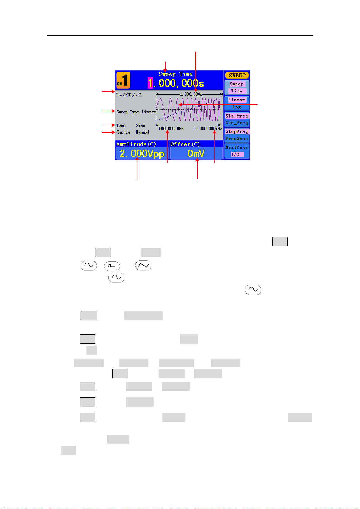
Current Parameter
Sweep Waveform
Load
Sweep Type
Sweep Time
Sweep Waveform
Source
Sweep Waveform
Amplitude
Sweep Waveform
Offset
Start
Frequency
Stop
Frequency
Figure 5-21: The User Interface of Sweep Mode
How to set the parameters of Sweep
(1) When the output signal is Sine, Square or Ramp waveform, press the Mod button,
then press F2 to select Sweep to enter the Sweep mode.
(2) Press , or button to choose the waveforms. Take Sine for
instance, press to display the waveform and parameters. You can change the
parameters, please refer to To set signals on page 12. Press button again to
return to the Sweep mode interface.
(3) Press F1 to set Sweep Time, the T ime Span of the Sweep for which the
Frequency changes from the Start Frequency to Stop Frequency.
(4) Press F2 to select the Sweep Type. Linear means setting the Sweep with linear
spacing; Log means setting the Sweep with logarithmic spacing.
(5) Use Start Freq and Stop Freq or Center Freq and Freq Span to set the range of the
frequency. Press F3 to select Sta_Freq or Cen_Freq, and set the desired value.
(6) Press F4 to select StopFreq or FreqSpan, and set the desired value.
(7) Press F5 to select NextPage, press it again to enter the next page.
(8) Press F1 to select the source. Internal means using the internal source. External
means using the Ext Trig/Burst/Fsk In connector in the rear panel to input the
external signal. Manual means choosing manual trigger; in Sweep interface, press the
knob on the front panel to trigger a Sweep.
Page 36
5.Front Panel Operation
31
Term Explanation
Burst:
Generally it is called BURST function within
m cycles, and every burst is activated by a
Gated burst use external source to control burst as when to be activated.
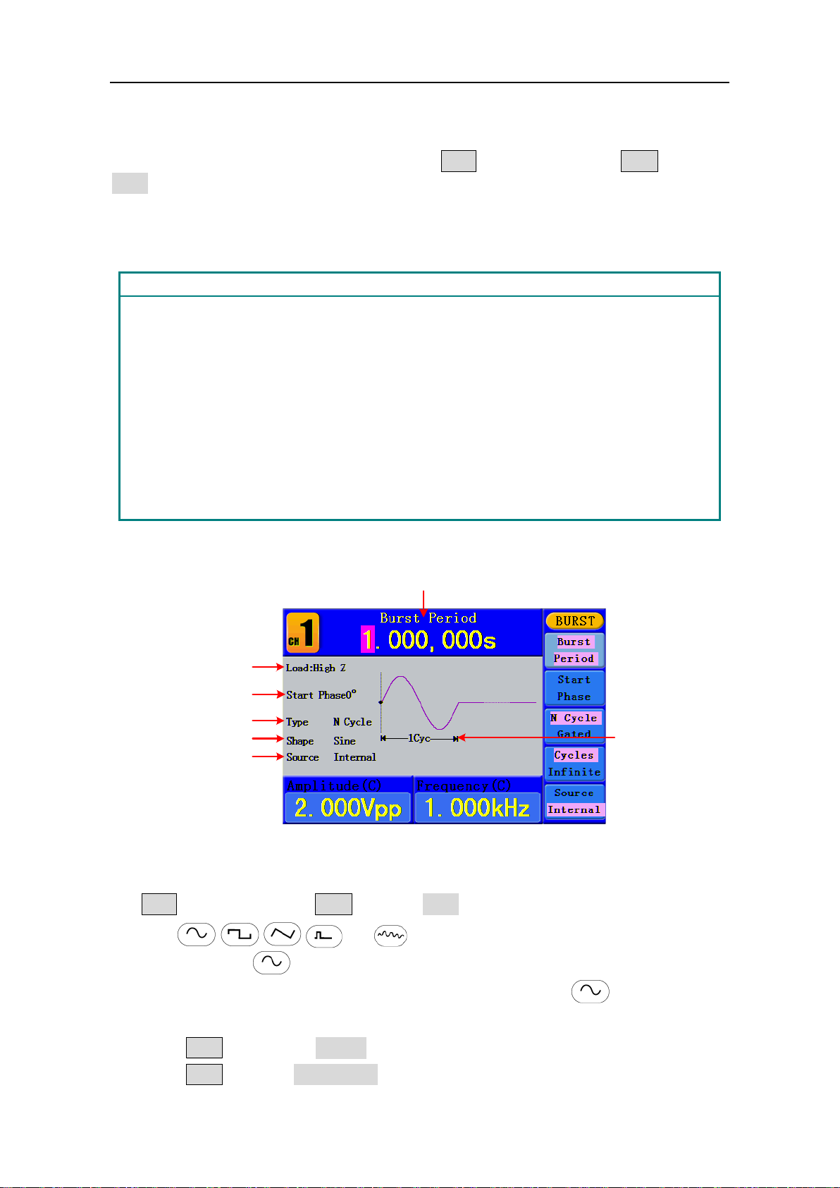
Current Parameter
Cycles
Load
Start Phase
N Cycle
Waveform
Source
To Generate Burst
Burst function is only used for CH1. Press the Mod button, then press F3 to select
Burst to generate versatile waveforms in burst. Burst can last for certain times of
waveform cycle (N-Cycle Burst), or to be controlled by external gated signals (Gated Burst).
Bust can apply to Sine, Square, Ramp, Pulse and Arbitrary waveforms (Noise can not be
used).
Output Waveforms with set cycle times.
every Signal Generator.
N-Cycle Burst:
N-Cycle has specific number of wavefor
trigger event.
Gated Burst:
Set the N-Cycle Burst
Figure 5-22: The User Interface of N-Cycle Burst
(1) When the output signal is Sine, Square, Ramp, Pulse or Arbitrary waveform, press the
Mod button, then press F3 to select Burst.
(2) Press , , ,
or
button to choose the waveform. Take Sine for
instance, press to display the waveform and parameters. You can change the
parameters, please refer to To set signals on page 12. Press button again to
return to the Burst mode interface.
(3) Press F3 to switch to N Cycle.
(4) Press F1 to select Burst Period, set it to the desired value.
Page 37
5.Front Panel Operation
32
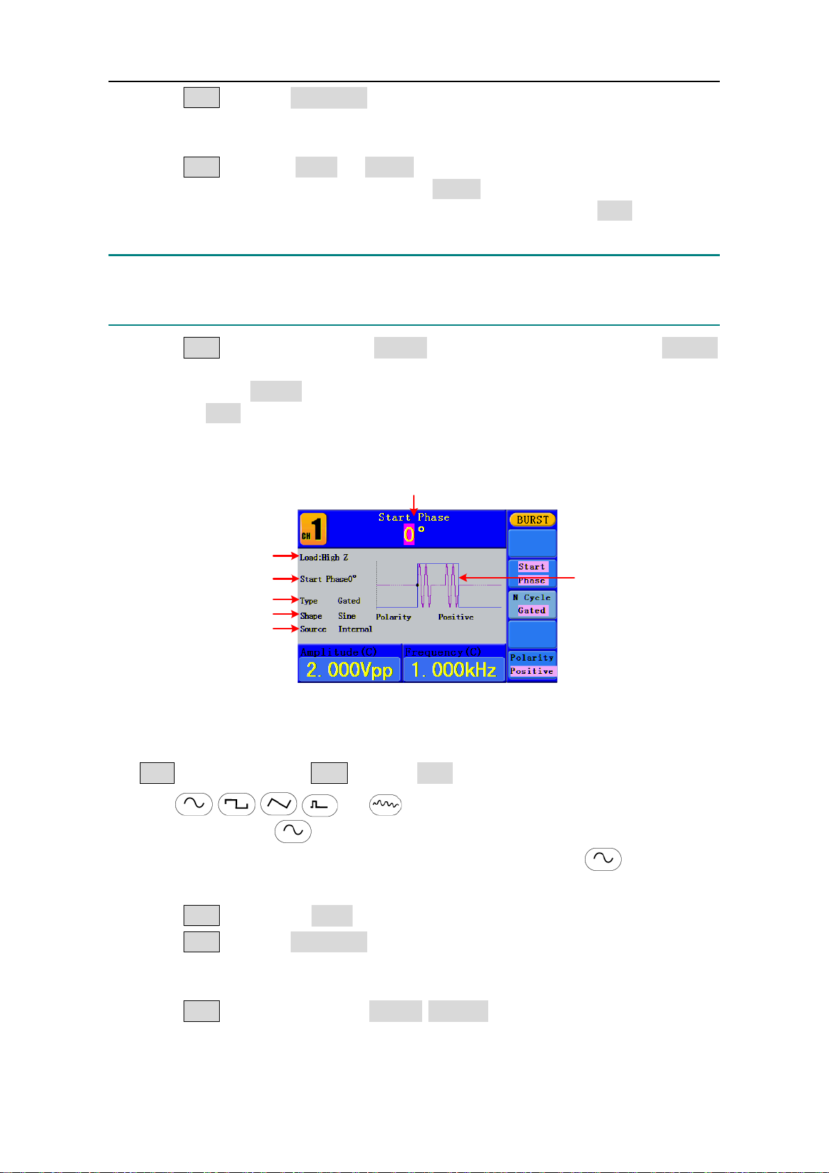
Current Parameter
Positive
Load
Start Phase
Gated
Waveform
Source
(5) Press F2 to select Start Phase (if current waveform is Pulse, skip this step), define
the Start and the Stop Point in a waveform. The phase varies from -360° to +360°. For
an Arbitrary Waveform, 0° is the first waveform point.
(6) Press F4 to select Cycles or Infinite. Set the number of Waveform Cycle in an
N-Cycle (from 1 to 50,000). If you choose Infinite, then a continuous waveform will
be generated which will not stop until a trigger event happens (the knob on the front
panel is pressed).
Note:
● If needed, Burst Period will increase to cater to the specific number of cycles.
● For an infinite-cycle Burst, External or Manual Trigger is needed to activate burst.
(7) Press F5 to select the source. Internal means using the internal source. External
means using the Ext Trig/Burst/Fsk In connector in the rear panel to input the
external signal. Manual means choosing manual trigger; in N-Cycle Burst interface,
press the knob on the front panel to output a burst signal.
Set the Gated Burst
Figure 5-23: The User Interface of Gated Burst
(1) When the output signal is Sine, Square, Ramp, Pulse or Arbitrary waveform, press the
Mod button, then press F3 to select Burst.
(2) Press , , ,
or
button to choose the waveforms. Take Sine
for instance, press to display the waveform and parameters. You can change
the parameters, please refer to To set signals on page 12. Press button again
to return to the Burst mode interface.
(3) Press F3 to switch to Gated.
(4) Press F2 to select Start Phase, define the Start and the Stop Point in a waveform.
The phase varies from -360° to +360°. For an Arbitrary Waveform, 0° is the first
waveform point.
(5) Press F5 to switch between Positive/Negative. Set the Polarity for the Gated
Signal.
Page 38
5.Front Panel Operation
33
To Save and Recall
Press Save function button to enter the file system.
To Use USB Storage
The storage location is divided into the internal storage (FLASH) and the USB device
storage (USBDEVICE). When a USB device is connected, the storage menu will show
"USBDEVICE" and "FLASH". Otherwise, the storage menu will show "FLASH" on ly.
(1) Install the USB device: insert a USB device into the "⑰USB port" on the front panel
in Figure 4-1, and the screen will show "Detect USB device". Press Save function
button to enter the file system, the storage menu will show "USBDEVICE" and
"FLASH".
(2) Enter the storage: Tu r n the knob or press / direction key to choose the
desired storage. Press F1 to enter the chosen storage. Provide operations as Next
level, Up one level, New folder, Delete, Rename, Copy, Paste.
(3) Remove the USB device: Remove the USB device from the USB port on the front
panel. The system will inform you "The USB device is removed", and the
"USBDEVICE" in the storage menu will disappear.
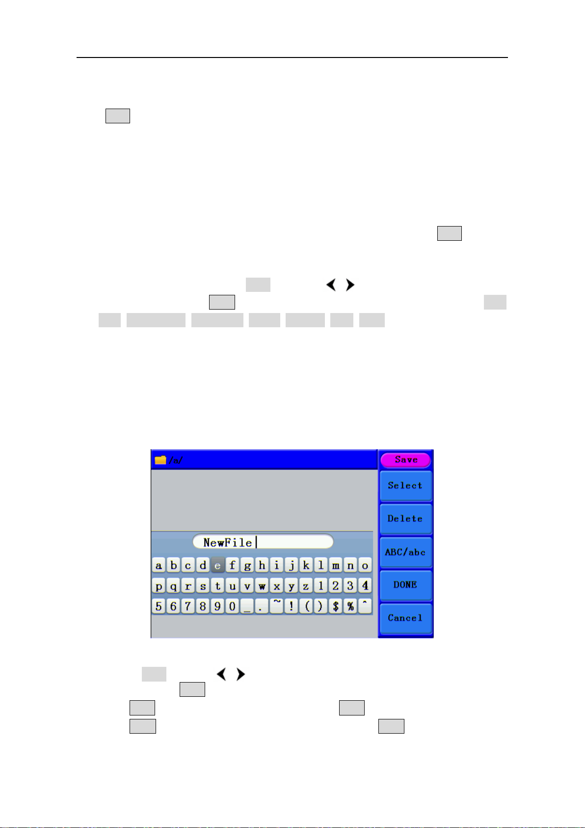
To Edit the File Name
In file system, the user can edit the name of a file or a fo ld er. When the system needs the
user to input a name, an input keyboard will appear.
Figure 5-24: Edit the File Name
(1) Turn the knob or press / direction key to move the cursor left and right in the
keyboard. Press F3 to switch between capital and small of the characters.
(2) Press F1 to enter the current character. Press F2 to delete the last character .
(3) Press F4 to finish editing and save the file. Press F5 to cancel the save
operation.
Page 39
5.Front Panel Operation
34
Note: The length of file name is up to 15 characters.
To Set the Utility Function
Press Utility function key to enter the Utility Menu. You can set the parameters of the
Generator such as: Display Parameter, Counter Parameter, Output Parameter and System
Setting. Press Utility again to exit the Utility Menu.
To Set Display Parameter
To Set the Bright
(1) Press Utility and choose Disp Setup, press F1 to select Bright.
(2) Turn the knob to change the value, press / direction key to move the cursor
left and right; or press the number keys to input the desired value in percent, press
F4 to select the unit. The bright range is 0% - 100%.
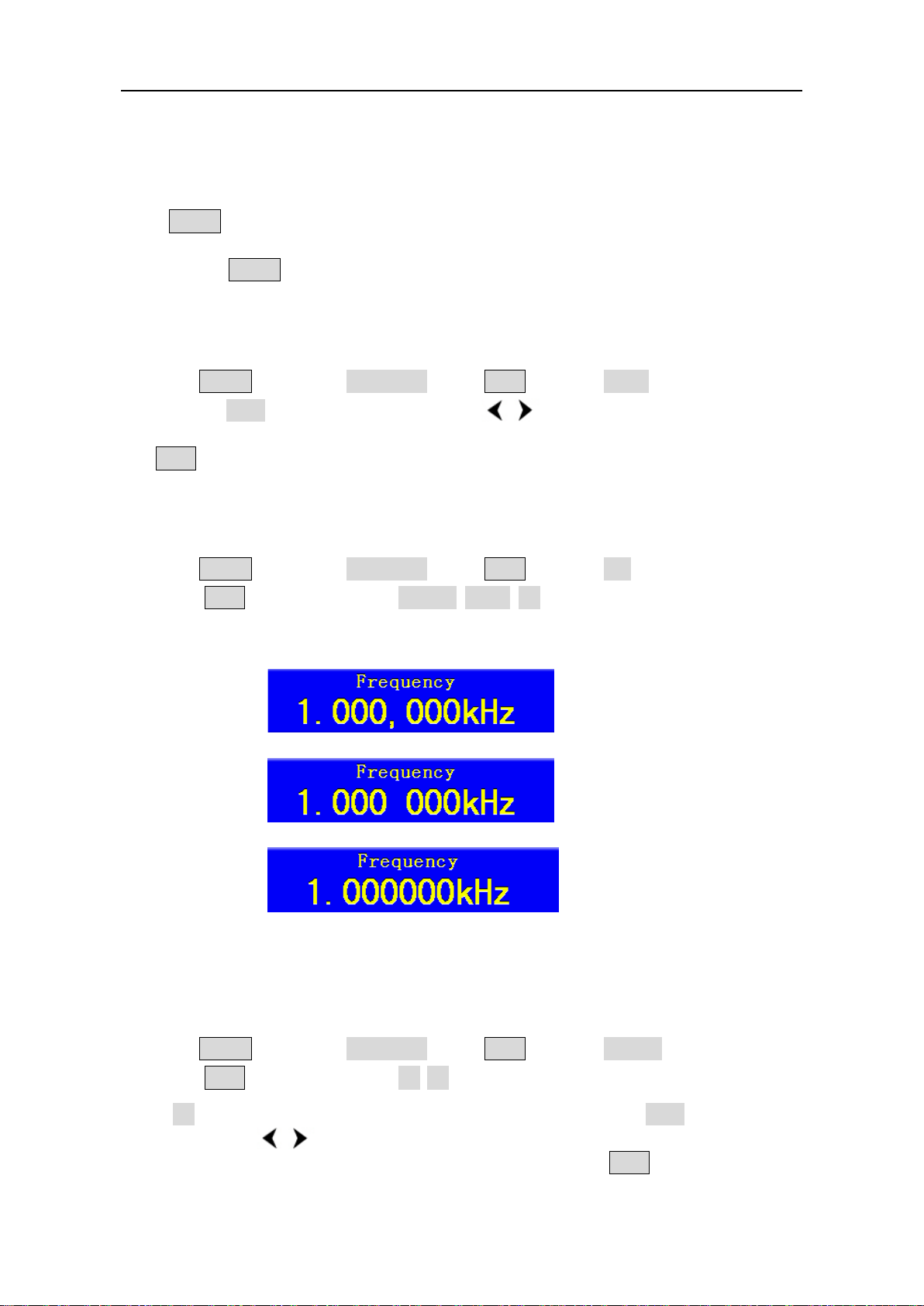
To Set the Separator
The user can set the separator of the displayed parameter.
(1) Press Utility and choose Disp Setup, press F2 to select Sep.
(2) Press F2 to switch between Comma, Space, Off.
Take the Frequency parameter for instance:
Comma
Space
Off
To Set the Screen Saver
The screen saver will run automatically if no operation is taken for any key within the set
time. Press any button to resume.
(1) Press Utility and choose Disp Setup, press F3 to select Scrn Svr.
(2) Press F3 to switch between On/Off.
(3) If On is selected, you can set the screen saver time. Turn the knob to change the
value, press / direction key to move the cursor left and right; or press the
number keys to input the desired time in minutes, press F4 to select the unit.
The screen saver time range is 1 - 999 minutes.
Page 40

5.Front Panel Operation
35
To Set the Counter
The counter can measure the signal with frequency form 100 mHz to 200 MHz.
The operation steps:
(1) Press Utility and choose Counter.
(2) Connect the signal to the connector [Ref Clk/Counter In] on the rear panel.
(3) Press F3 to choose Set, enter measurement setting menu.
To set the coupling mode: Press F1 to switch Coupling as AC/DC.
To set the sensitivity: Press F2 to switch Sens as Low/Middle/High.
For low amplitude signal, the “Middle” or “High” sensitivity should be used.
For low frequency signal with high amplitude and slower rising edge, low
sensitivity is a better choice.
To s et the high frequency restrain on/off: Press F3 to switch HFR as ON/ OF F.
High frequency restrain is used for filtering the high frequency signal in
measuring the low frequency signal, and improve the measure accuracy.
To measure low frequency signal lower than 1 kHz, you should put on the high
frequency restrain to filter the high frequency noise disturb.
To measure high frequency signal higher than 1 kHz, you should put off the high
frequency restrain.
To set the trig level: Press F4 to choose TrigLev. Turn the knob to change the
value, press / direction key to move the cursor left and right; or press the
number keys to input the desired value and choose the unit. The range of trig
levle is -2.5 V - 2.5 V.
Press F5 to choose Back to previous menu, view the result.
After all the set was done, the counter will measure the signal according to the
current set. If the reading is unsteady, please repeat the above step until it is steady.
(4) Press F1 to switch to view the measure result of frequency or period.
Press F2 to switch to view the measure result of positive width or duty.
To Set Output Parameter
To Set the Output Load
For either of CH1 Output and CH2 Output on the Front panel, the Generator has a built-in
50Ωseries impendence. If the actual load does not match the set one, the displayed
amplitude and offset are incorrect. This function is used to match the displayed voltage
with the expected one.
Steps for setting the Load of each channel:
(1) Press Utility and choose Output Setup. Press F1 to select CH1Load, or press
F2 to select CH2Load; press it again to select HighZ or *Ω ("*" represents a value).
(2) To change the load value, after selecting *Ω, turn the knob to change the value, press
/ direction key to move the cursor left and right; or press the number keys to
input the desired value. Press F3 or F4 to select the unit. The load range is
1 Ω - 10 kΩ.
Page 41
5.Front Panel Operation
36
Note:
For either of CH1 Output and CH2 Output on the Front panel, the waveform generator
has a fixed 50Ω Series Impendence. No matter what Value the set parameter is, if the real
load is different from the set one, the displayed voltage will not equal the real voltage.
To Set the Phase Deviation
You can set the phase deviation of the two channels.
(1) Press Utility and choose Output Setup, press F3 to select PhaseDev.
(2) Press F3 to switch between On/Off.
(3) If On is selected, you can set the value of phase deviation. Turn the knob to change
the value, press / direction key to move the cursor left and right; or press the
number keys to input the desired value in degree, press F4 to select the unit. The
phase deviation range is 0 - 360°.
To Set the System
Language Setting
Press Utility and choose System, press F1 to switch display languages.
Power On Setting
(1) Press Utility and choose System, press F2 to select Power On.
(2) Press F2 to switch between Default/Last. Default means that all the settings
return to default when powered. Last means that all the settings return to the last
one when powered.
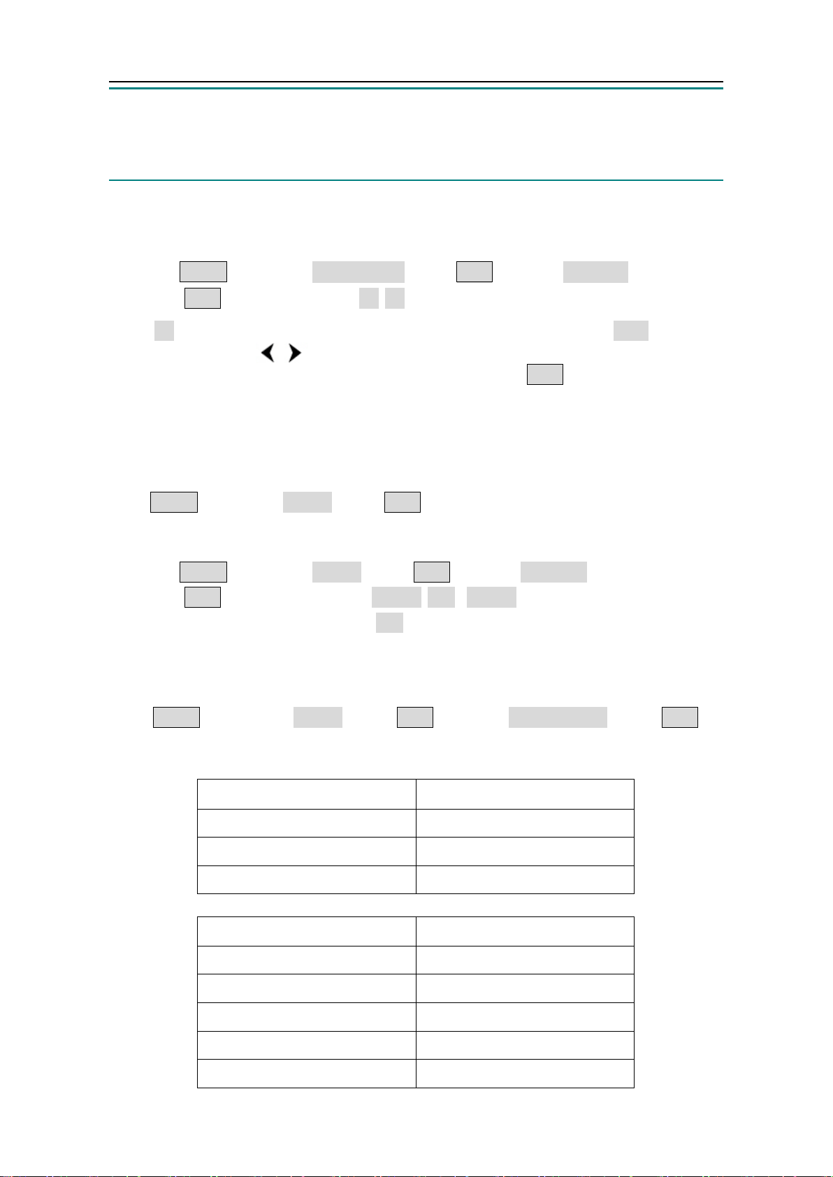
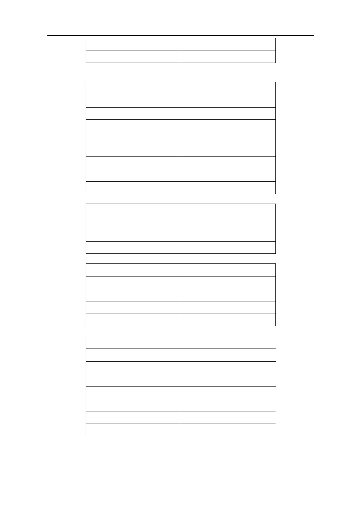
To Return to Default Setting
Press Utility and choose System, press F3 to select Set to Default, press F1 to
confirm. All the settings will be set to default. The default settings of the system are as
follows:
Output Default
Function Sine Wave
Frequency 1 kHz
Amplitude/Offset 1 V
/ 0 Vdc
p-p
Waveforms Default
Frequency 1 kHz
1 V
Amplitude
Offset
p-p
0 Vdc
Duty Cycle of Square 50%
Symmetry of Ramp 50%
Page 42
5.Front Panel Operation
37
Pulse Width of Pulse 200 us
Duty Cycle of Pulse 20%
Modulation Default
Carrier 1 kHz Sine Wave
Modulating 100 Hz Sine Wave
AM Depth 100%
FM Deviation 100 Hz
PM Phase Deviation 0°
FSK Hop Frequency 100 Hz
FSK Frequency 100 Hz
Source Internal
Sweep Default
Start/Stop Frequency 100 Hz/1 kHz
Time 1 sec
Mode Linear
Burst Default
Frequency 1 kHz
Count 1 Cycle
Period 1 sec
Phase 0°
Others Default
Brightness
95%
Separator Comma
Screen Saver time 100 minutes
Load High Z
Phase Deviation 0°
Clock Source Internal
Channel Output Control Off
Page 43
5.Front Panel Operation
38
To Set the Beep
(1) Press Utility and choose System, enter the second page of the menu.
(2) Press F1 to select Beep.
(3) Press F1 to switch between On/Off. On is to activate the sound when the system
informs you. Off is to deactivate it.
View System Information
(1) Press Utility and choose System, enter the second page of the menu.
(2) Press F2 to select Sys info. You can view the Version and Serial number.
To Set the Clock Source
The waveform generator provides an internal clock source and also accepts external clock
source input from the [Ref Clk/Counter In] connector at the rear panel. It can also output
a clock source from the [Ref Clk Out] connector for other device to use.
Note:
The amplitude of the [Ref Clk/Counter In] input signal must be over 1 V.
(1) Press Utility and choose System, enter the second page of the menu.
(2) Press F3 to select CLK Sou.
(3) Press F3 to switch between Internal/External.
To Use Built-in Help
(1) Press Help function button, the catalog will display in the screen.
(2) Press F1 or F2 to choose help topic, or just turn the knob to choose.
(3) Press F3 to view the details about the topic; press F5 to go back to the
catalog.
(4) Press Help again to exit the help, or just do other operations.
Page 44

6.Communication with PC
39
6. Communication with PC
The Waveform Generator supports communications with a PC through USB port. You can
use the ultrawave communication software to set the parameters, control the output of
the Waveform Generator.
The Waveform Generator supports communications with a PC by SCPI commands
through USB port.
Here is how to connect with PC. Install the ultrawave communication software on the
supplied CD.
(1) Connection: Use a USB data cable to connect the USB (type B) connector on the rear
panel of the Waveform Generator to the USB port of a PC.
(2) Install the driver: When the Waveform Generator is turned on, a dialog will appear
on the PC screen and guide you to install the USB driver. The driver is in the
"USBDRV" folder under the directory where the ultrawave communication software
is installed, such as "C:\Program Files\OWON\ultrawave\USBDRV".
(3) Port setting of the software: Run the ultrawave software; click "Communications" in
the menu bar, choose "Ports-Settings", in the setting dialog, choose "Connect using"
as "USB". After connect successfully, the connection information in the bottom right
corner of the software will turn green.
For the detail communication protocol of SCPI, please refer to AG Series Waveform
Generator SCPI Protocol.
To learn about how to operate the software, press F1 in the software to open the help
document.
Page 45

7.SCPI
40
7. SCPI
The waveform generator supports SCPI, and the users can operate and control the device by USB port.
For the detailed information about SCPI, please refer to
Protocol.
AG Series Waveform Generator SCPI
8. Troubleshooting
1. The instrument is powered on but no Display.
Check if the power is connected properly.
Check if the Power Switch is in the proper voltage scale.
Check if the fuse which is below the AC Power socket is used appropriately and
in good condition (the cover can be pried open with a straight screwdriver).
Restart the instrument after the steps above.
If the problem still exists, please contact Lilliput for our service.
2. The measured value of output signal amplitude disaccords to the displayed value:
Check if the actual load matches the set one. Please refer to To Set the Output Load
on page 35.
If you encounter other problems, try to reset the settings (refer to To Return to Default
Setting on page 36) or restart the instrument. If it still can not work properly, please
contact Lilliput for our service.
Page 46
9.Technical Specifications
41
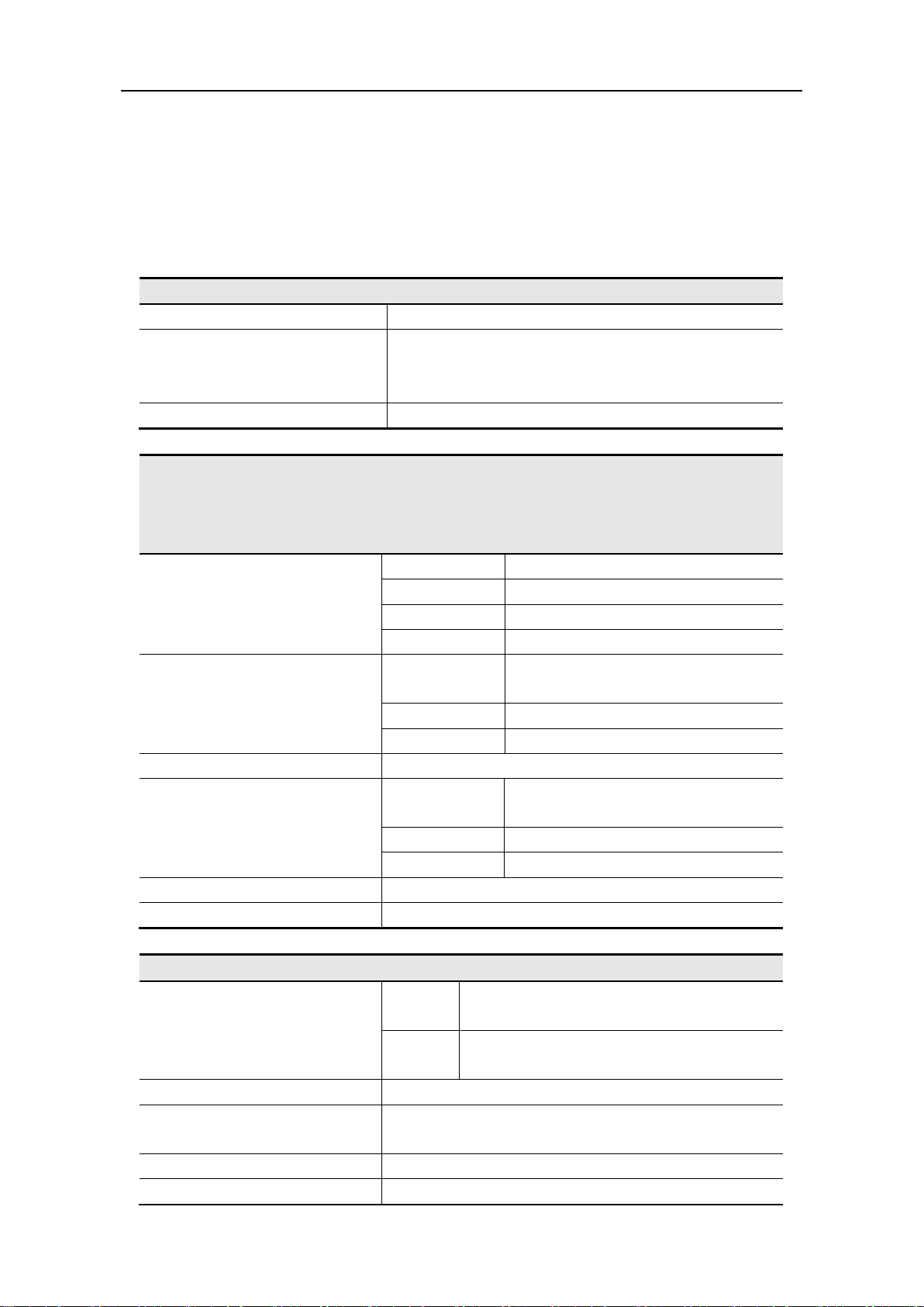
Waveforms
Standard Waveforms
Sine, Square, Ramp, Pulse, Noise
Staircase,
Waveform
Numbers of channel
2
Frequency Characteristic
Sine
AG1012F
1 μHz—10 MHz
AG1022F
1 μHz—25 MHz
AG2052F
1 μHz—50 MHz
AG2062F
1 μHz—60 MHz
Square
AG1012F
AG1022F
1 μHz—5 MHz
AG2052F
1 μHz—25 MHz
AG2062F
1 μHz—30 MHz
Ramp
1 μHz—1MHz
Pulse
AG1012F
AG1022F
1 μHz—5 MHz
AG2052F
1 μHz—10 MHz
AG2062F
1 μHz—15 MHz
White Noise
25 MHz bandwidth (-3 dB) (typical)
Arbitrary
1 μHz—10 MHz
Amplitude Characteristic
10 MHz to 25 MHz: 1 mVPP-10 VPP
1 μHz to 10 MHz:
0.5 mVPP-10 VPP
10 MHz to 25 MHz: 0.5 mVPP-5 VPP
Amplitude Accuracy
1 mVPP or 14 bits
±5 V (50 Ω)
±10 V (High Z)
DC Offset Accuracy
1 mV
Output Impedance
50 Ω (typical)
9. Technical Specifications
All these specifications apply to the Waveform Generator unless otherwise
explanation. To reach these specifications, the instrument must have been operating
continuously for more than 30 minutes within the specified operating temperature.
All the specifications are guaranteed unless those marked with “typical”.
Exponential rise, Exponential fall, Sin(x)/x,
Arbitrary Waveforms
Frequency resolution: 1 μHz
AG1012F,AG1022F Max sampling rate 125 MSa/s, AG2052F ,AG2062F Max sampling rate
250 MSa/s
etc. 45 built-in waveforms, User-Definable
Output Amplitude
DC Offset Range (AC+DC)
High Z
50 Ω
1 μHz to 10 MHz: 1 mVPP-20 VPP
Page 47
9.Technical Specifications
42
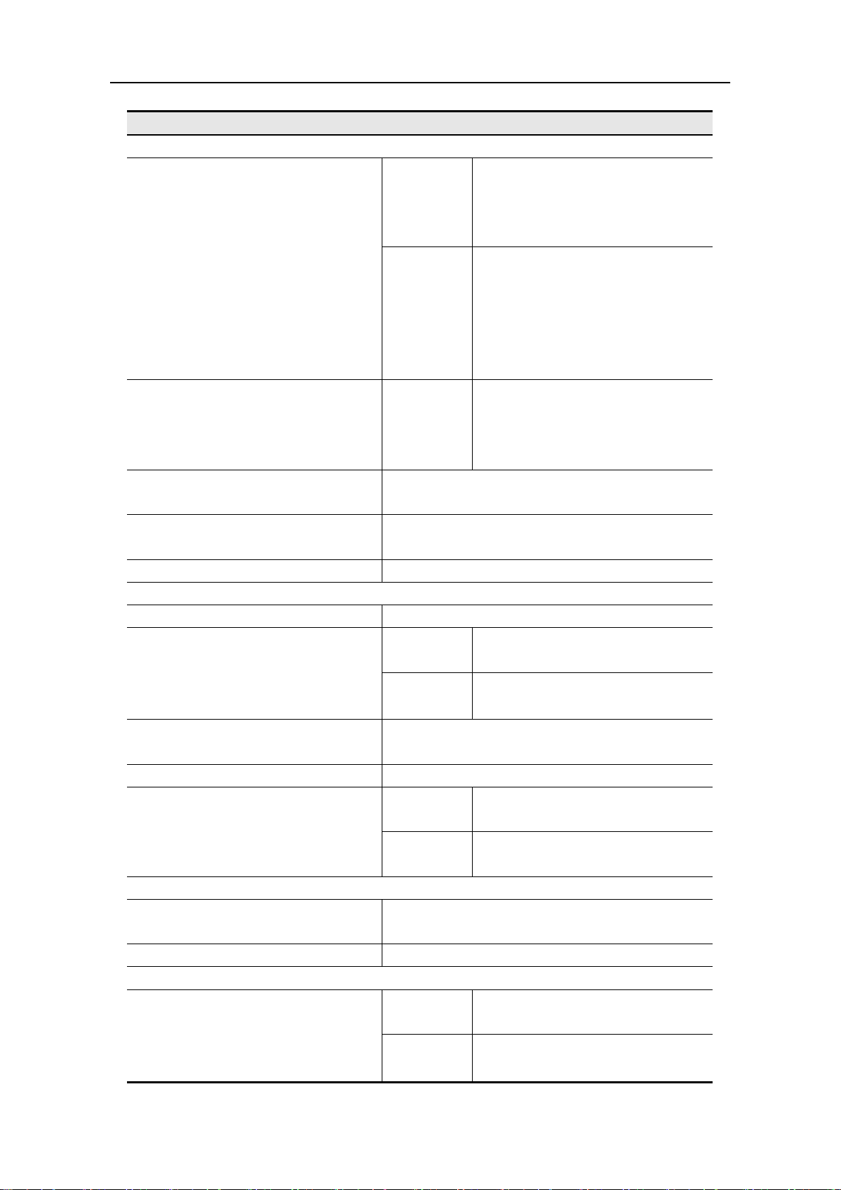
Waveform Characteristic
Sine
1 μHz to 10 MHz
0.3 dB ± 1 mv
1 μHz to 10 MHz
0.5 dB ± 1 mv
AG1012F
Total Harmonic Distortion (when
the Amplitude is 1 V
p-p
)
is 1 V
p-p
)
Residue Clock Noise
-57 dBm (typical)
Square
Rise/Fall Time
<12 ns (10% - 90%) (typical, 1 kHz, 1 V
p-p
)
AG1022F
AG2052F
Cycle)
Overshoot
< 5%
AG1012F
AG1022F
20% - 80% (< 1 MHz)
50% (1 MHz - 5 MHz)
AG2052F
AG2062F
20% - 80% (< 10 MHz)
50% (> 10 MHz)
Ramp
< 0.1% of peak output (typical, 1 kHz, 1 V
,
Symmetry 50%)
Symmetry
0% to 100%
Pulse
AG1022F
AG2052F
:
AG1012F
AG1022F
0.2 dB ± 1 mv
10 MHz to 25 MHz:
Flatness (when the Amplitude is
1.0 V
(+4 dBm), relative to
p-p
1 kHz)
Harmonic Distortion (when the
Amplitude is 1.0 V
p-p
)
Phase Noise (when the Amplitude
Jitter (rms)
0.2 dB ± 1 mv
AG2052F
AG2062F
10 MHz to 25 MHz:
0.3 dB ± 1 mv
25 MHz to 50 MHz:
AG1022F
AG2052F
<-40 dBc
AG2062F
10 Hz to 20 kHz: <0.2 %
-110 dBc/Hz
AG1012F
AG2062F
1 ns + 30 ppm
300 ps + 100 ppm of period
:
Non-symmetry (below 50% Duty
Duty Cycle
Linearity
Pulse Width
1% of period+ 5 ns
AG1012F
AG2062F
40 ns to 1000 ks
20 ns to 1000 ks
p-p
Page 48
9.Technical Specifications
43
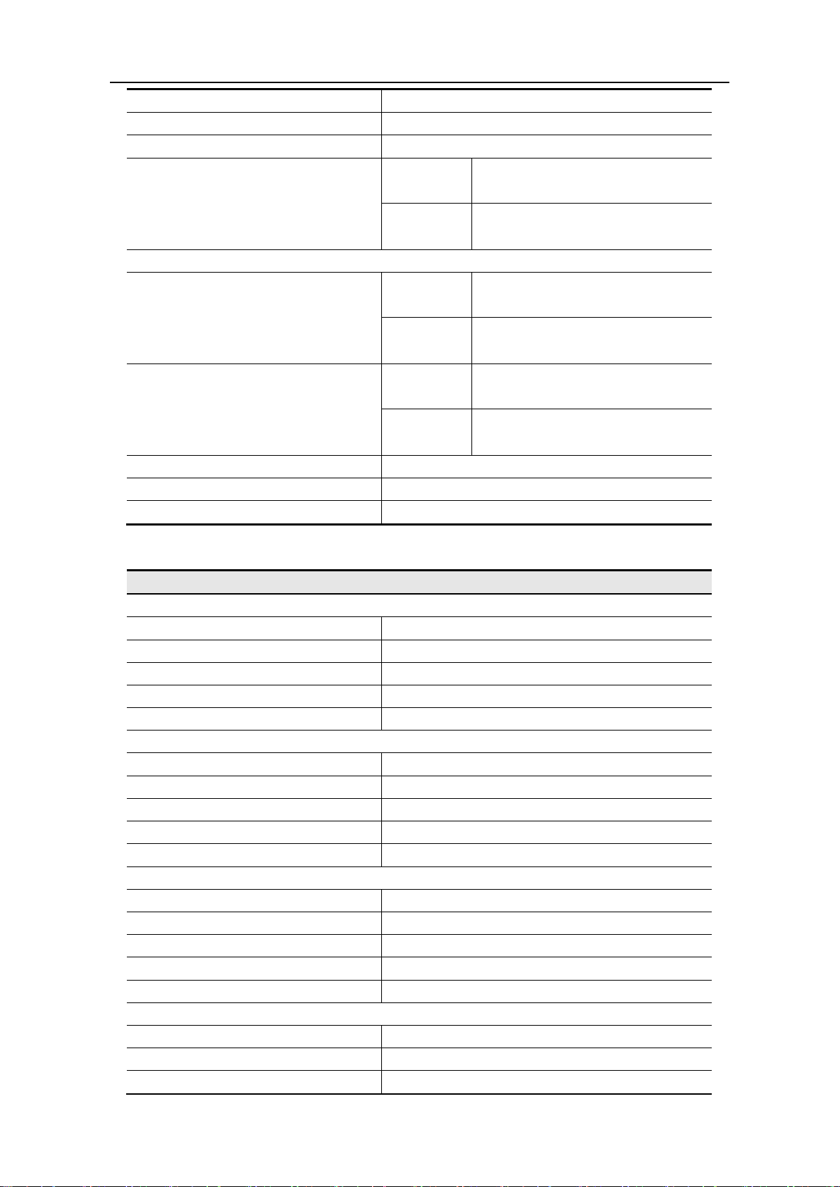
Accuracy
10 ns
Rising/Falling Edge Time
< 12 ns
Overshoot
< 5%
AG1022F
AG2052F
Arbitrary
AG1022F
AG2052F
AG1012F
AG1022F
AG2052F
Amplitude Accuracy
14 bits
Minimum Rise/Fall Time
35 ns (typical)
Jitter (RMS)
6 ns + 30 ppm
Modulated Waveform
AM
Carrier Waveforms
Sine
Source
Internal/ External
Internal Modulating Waveforms
Sine, Square, Ramp, White Noise, Arbitrary
Internal AM Frequency
2 mHz - 20 kHz
Depth
0.0% - 100.0%
FM
Carrier Waveforms
Sine
Source
Internal/ External
Internal Modulating Waveforms
Sine, Square, Ramp, White Noise, Arbitrary
Internal Modulating Frequency
2 mHz - 20 kHz
Frequency Deviation
2 mHz - 20 MHz
PM
Carrier Waveforms
Sine
Source
Internal/ External
Internal Modulating Waveforms
Sine, Square, Ramp, White Noise, Arbitrary
Internal PM Frequency
2 mHz - 20 kHz
Phase Deviation
0° - 180°
FSK
Carrier Waveforms
Sine
Source
Internal/ External
Internal Modulating Waveforms
50% duty cycle square
Jitter
Waveform Length
Sample Rate
AG1012F
AG2062F
AG1012F
AG2062F
AG2062F
1 ns + 30 ppm
300 ps + 100 ppm of period
2 – 8k points
2 - 1M points
125 MSa/s
250 MSa/s
Page 49
9.Technical Specifications
44
FSK Rate
2 mHz - 100 kHz
PWM (only in AG2052F and AG2062F)
Carrier Waveforms
Pulse
Source
Internal/ External
Internal Modulating Waveforms
Sine, Square, Ramp, Arbitrary
Internal Modulating Frequency
2 mHz - 20 kHz
Width Deviation
Pulse width 0.0 ns to 200.00 usec
Sweep
Type
Linear, Logarithmic
Carrier Waveforms
Sine, Square, Ramp
Direction
Up / Down
Sweep Time
1 ms to 500 s ± 0.1%
Source
Source, External or Manual
Burst
Waveforms
Sine, Square, Ramp, Pulse, Arbitrary
Types
Count (1 to 1,000,000 periods), infinite, gated
Start Phase
-360° - +360°
Internal Period
(10 ms - 500 s) ± 1%
Gated Source
External Trigger
Trigger Sources
Source, External or Manual
Counter Specification
Function
Frequency, period, positive Pulse width, Duty cycle
Frequency Range
Single channel: 100 mHz - 200 MHz
Frequency Resolution
6 digits
Voltage Range and Sensitivity (non-modulation signal)
DC offset range
±1.5 VDC
100 mHz - 100 MHz
250 mV
p-p
- 5 V
p-p
(AC+DC)
100 MHz - 200 MHz
450 mV
p-p
- 3 V
p-p
(AC+DC)
1 Hz - 100 MHz
250 mV
p-p
- 5 V
p-p
100 MHz - 200 MHz
450 mV
p-p
- 4 V
p-p
Pulse width and
Measure
Input impedance
1 MΩ
Coupling mode
AC, DC
High frequency noise restrain (HFR)
On or Off
sensitivity
Low, Middle, High
Trigger level range
2.5 V
Input/Output
Channel Coupling, Channel Copy
Phase Deviation
0 - 360°
Rear Panel
DC coupled
AC coupled
Duty cycle
Input adjust
1 Hz - 10 MHz (100 m V
High frequency restrain
- 10 V
p-p
p-p
)
±
Page 50
45
Interfaces
USB (type B) connector
External Modulation Input
Input Frequency Range
DC-20 kHz
Input Voltage Range
± 5 Vpk
Input Impedance
10 kΩ (typical)
External Trigger Input
Level
TTL-compatible
Slope
Rising or falling (selectable)
Pulse Width
>100 ns
Trigger Delay
0.0 ns - 60 s
External Reference Clock Input
Impedance
1 kΩ, AC coupled
Requested Input voltage swing
100 mV
p-p
to 5 V
p-p
locking range
20 MHz ± 35 kHz
Counter Input (share the same port as External Reference Clock Input)
DC coupled
DC offset range
±1.5 VDC
100 mHz - 100 MHz
250 mV
p-p
- 5 V
p-p
(AC+DC)
100 MHz - 200 MHz
450 mV
p-p
- 3 V
p-p
(AC+DC)
1 Hz - 100 MHz
250 mV
p-p
- 5 V
p-p
100 MHz - 200 MHz
450 mV
p-p
- 4 V
p-p
External Reference Clock Output
Impedance
50 kΩ, AC coupled
Amplitude
5 V
p-p
, access 50 Ω
Display Type
3.9 inch colored LCD (Liquid Crystal Display)
Display Resolution
480 (Horizontal) × 320 (Vertical) Pixels
Display Colors
65536 colors, 16 bits, TFT screen
Supply
220-230 VAC, 100-110 VAC, 50/60 Hz, CATⅡ
Consumption
Less than 18 W
110 V
125 V, F4AL
220 V
250 V, F2AL
Working temperature: 0℃ - 40℃
Storage temperature: -20℃ - 60℃
Relative Humidity
≤ 90%
Operating: 3,000 m
Non-operating: 15,000 m
Cooling Method
Natural cooling
9.Technical Specifications
AC coupled
Display
Power
Fuse
Environment
Temperature
Height
Mechanical Specifications
Page 51

9.Technical Specifications
46
Dimension 235 mm × 110 mm × 295 mm (W*H*D)
Weight 3 kg
Interval Period of Adjustment:
One year is recommended for the calibration interval period.
Page 52

10.Appendix
47
Warn
Before power on again for operation, it is required to confirm that
een dried completely, avoiding any
10. Appendix
Appendix A: Enclosure
Standard Accessories:
A power cord that fits the standard of the destination country
A USB cable
A CD (PC link application software)
A Quick Guide
A BNC/Q9 cable
Appendix B: General Care and Cleaning
General Care
Do not store or leave the instrument where the liquid crystal display will be exposed
to direct sunlight for long periods of time.
Caution: To avoid any damage to the instrument, do not exposed it to any sprays,
liquids, or solvents.
Cleaning
Inspect the instrument as often as operating conditions require.
To clean the instrument exterior, perform the following steps:
1. Wipe the dust from the instrument surface with a soft cloth. Do not make any
scuffing on the transparent LCD protection screen when clean the LCD screen.
2. Disconnect power before cleaning your instrument. Clean the instrument with a
wet soft cloth not dripping water. It is recommended to scrub with soft
detergent or fresh water. To avoid damage to the instrument, do not use any
corrosive chemical cleaning agent.
ing:
the instrument has already b
electrical short circuit or bodily injury resulting form the moisture.
 Loading...