

Page 1

1
OV804WV
User Manual
Page 2

Error! Use the Home tab to apply 标题 to the text that you want to appear
here.Error! Use the Home tab to apply 标题 to the text that you want to
appear here.
i
Contents
1 Introduction .......................................................................... 1
1.1 Application ............................................................. 1
1.2 Features ................................................................ 1
1.3 Wireless Specifications .......................................... 2
1.4 Compliance Certificates ........................................ 4
1.5 Standards Compatibility and Compliance ............. 4
1.6 Supported Encapsulation ...................................... 5
1.7 Environment Requirements ................................... 5
1.8 System Requirements ........................................... 5
1.9 Package List (according to the actual package) ... 8
1.10 Safety Cautions ..................................................... 8
1.11 LED Status Description ......................................... 9
1.11.1 LED Status ..................................................... 9
1.11.2 Rear Panel ................................................... 10
2 Hardware Installation .......................................................... 11
2.1 Choosing the Best Location for Wireless Operation
11
2.2 Connecting the VDSL Router .............................. 12
2.3 Factory Reset Button ........................................... 13
3 Connection ......................................................................... 14
3.1 About DSL Router ............................................... 14
3.2 Setup ................................................................... 15
3.2.1 Setting up WAN and LAN Connections ....... 15
3.2.2 PC Network Configuration ........................... 16
4 Web-Based Management .................................................. 19
4.1 Logging In to the DSL Router .............................. 20
4.1.1 First-Time Login ........................................... 20
4.2 Quick Setup ......................................................... 21
4.2.1 WAN Interface Setup ................................... 22
4.2.2 LAN Interface Setup ..................................... 34
4.2.3 Wireless Interface Setup .............................. 35
4.2.4 WAN Setup Summary .................................. 36
Page 3

ii
4.2.5 Quick Setup Completion .............................. 37
4.3 DSL Router Device information ........................... 38
4.3.1 Summary of Device information ................... 38
4.3.2 WAN Interface Information ........................... 40
4.3.3 Statistics ....................................................... 40
4.3.4 Route Table Information ............................... 46
4.3.5 ARP Table Information ................................. 47
4.3.6 DHCP IP Lease Information ......................... 47
4.4 Advanced Setup .................................................. 48
4.4.1 WAN Configuration ...................................... 49
4.4.2 LAN Configuration ........................................ 87
4.4.3 NAT............................................................... 93
4.4.4 Security ...................................................... 104
4.4.5 Quality of Service ........................................ 116
4.4.6 Routing ....................................................... 129
4.4.7 DNS ............................................................ 134
4.4.8 Port Mapping .............................................. 136
4.4.9 Certificate ................................................... 141
4.5 Wireless ............................................................. 145
4.5.1 Overview .................................................... 146
4.5.2 Wireless LAN Basics .................................. 147
4.5.4 Configuration Example ............................... 181
4.6 Voice .................................................................. 184
4.6.1 Overview .................................................... 184
4.6.2 Web Page Introduction............................... 190
4.6.3 VoIP functionality ........................................ 197
4.6.4 Configuration Example ............................... 202
4.7 USB Storage ...................................................... 206
4.7.1 FTP Server Configure ................................ 207
4.8 Diagnostics ........................................................ 209
4.9 Management ...................................................... 210
4.9.1 Settings ...................................................... 210
4.9.2 System Log ................................................ 212
4.9.3 TR-69 Client Management ......................... 214
4.9.4 Internet Time .............................................. 217
4.9.5 Access Control ........................................... 218
Page 4

iii
4.9.6 Update Software ........................................ 221
4.9.7 Save/Reboot .............................................. 221
Page 5

Error! Use the Home tab to apply 标题 to the text that you want to appear
here.Error! Use the Home tab to apply 标题 to the text that you want to
appear here.
1
1 Introduction
The OV804WV (also called the device or the DSL Router
hereinafter), a VDSL2 integrated access device (IAD), is an
advanced all-in-one gateway. It incorporates VoIP, Ethernet
switch, and wireless home networking access point, and
complies with IEEE 802.11b/g standards. It can provide high
access performance application for individual users, SOHOs,
and small enterprises.
1.1 Application
Home gateway
SOHO
Small enterprises
Voice over IP (VoIP)
TV over IP (IPTV)
Higher data rate broadband sharing
Shared broadband Internet access
Audio and video streaming and transfer
PC file and application sharing
Network and online gaming
1.2 Features
4 x 10/100 Ethernet ports
1 x USB 2.0 host port
DSL2:
– 0 km: 40000 Kbps for upstream, 79900 Kbps for
downstream.
– 600m: 8000 Kbps for upstream, 40000 Kbps for
downstream
User-friendly GUI for Web configuration
Page 6

2
Several pre-configured popular games. Just enable the
game and the port settings are automatically configured.
Configurable as a DHCP server on your network
Compatible with all standard Internet applications
Industry standard and interoperable DSL interface
Support virtual server, IP filter, and DMZ host
Simple Web-based status page, displaying a snapshot of
system configuration and links to the configuration pages
Downloadable flash software updates
Support up to 16 permanent virtual circuits (PVCs)
Support up to 8 PPPoE sessions
Support SNMP v2, RIP v1, RIP v2, and NAT
WLAN with high-speed data transfer rates of up to 54
Mbps, compatible with IEEE 802.11b/g 2.4 GHz compliant
equipment
1.3 Wireless Specifications
Network Standard
IEEE 802.11b and IEEE 802.11g
Frequency Range
2.40 GHz~2.4835 GHz ISM band
Modulation
802.11b: DBPSK, DQPSK, CCK
802.11g: BPSK, QPSK, 16QAM, 64QAM
RF Power
802.11b: 20dBm (max). Typ. 18 dBm @
Normal Temp Range
802.11g: Typ. 15 dBm @ Normal Temp
Range
AP Capacity
Access User
Quantity
1~16 Pcs/AP (recommended)
Channels
US and Canada: 11
Europe and China: 13
Japan: 14
Page 7

3
Auto-sensing
data rate
802.11.b: 1 Mbps, 2
Mbps, 5.5 Mbps, 11 Mbps
802.11g: 6 Mbps, 9 Mbps,
12 Mbps, 18 Mbps, 24
Mbps, 36 Mbps, 48 Mbps,
54 Mbps
Payload Rate
1 Mbps DBPSK @ 0.81 Mbps
2 Mbps DQPSK @ 1.58 Mbps
5.5 Mbps CCK @ 4.07 Mbps
6 Mbps BPSK @ 4.64 Mbps
9 Mbps BPSK @ 6.55 Mbps
11 Mbps CCK @ 7.18 Mbps
12 Mbps BPSK @ 8.31 Mbps
18 Mbps QPSK @ 11.5 Mbps
24 Mbps 6QAM @ 14.18 Mbps
36 Mbps 16QAM @ 18.31 Mbps
48 Mbps 64QAM @ 23.25 Mbps
54 Mbps 64QAM @ 26.12 Mbps
Security
64-bit/128-bit WEP, 802.1x, WPA, WPA2
User Isolation
MAC level
MAC Filter
Ethernet
interface
MAC filter
Support
Vacancy
MAC filter
Support
Authentication
DHCP client
& static IP
address
Support
802.1x and
Radius client
Support
Page 8

4
DHCP
server
Support
Radio Cover Rage
(m)
Outdoors: 120~400
Indoors: 35~100
Antenna Type
Internal diversity with connector: 2dBi
1.4 Compliance Certificates
FCC Class B
CE Mark
1.5 Standards Compatibility and
Compliance
RFC 2684 Multiprotocol Encapsulation over ATM
Adaptation Layer 5
RFC1483 Multiprotocol Encapsulation over ATM
Adaptation Layer 5
RFC2364 PPP over ATM ALL5 (PPPoA)
RFC2516 PPP over Ethernet (PPPoE)
RFC1662 PPP in HDLC-like Framing
RFC1332 PPP Internet Protocol Control Protocol
RFC1577/2225 Classical IP and ARP over ATM (IPoA)
RFC1483R
RFC894 A standard for the transmission of IP Datagrams
over Ethernet networks
RFC1042 A standard for the transmission of IP Datagrams
over IEEE 802 networks
MER (a.k.a IP over Ethernet over AAL5)
Support application level gateway (ALG)
ITU G.992.3 (VDSL2)
ANSI T1.413 Issue 2
IEEE 802.3
IEEE 802.3u
Page 9

5
IEEE 802.11b
IEEE 802.11g
RFC3261 (SIP for VoIP)
1.6 Supported Encapsulation
RFC 1483 bridge
RFC 1483 router
Classical IP over ATM (RFC 1577)
PPP over ATM (RFC 2364)
PPP over Ethernet (RFC 2516)
1.7 Environment Requirements
Operating temperature: 0˚C~40˚C (32ºF~104ºF)
Storage temperature: -10˚C~55˚C (14ºF~131ºF)
Operating humidity: 10%~95%, non-condensing
Storage humidity: 5%~95%, non-condensing
1.8 System Requirements
Recommended system requirements are as follows:
Pentium 233 MHz or higher
Memory: 64 MB or higher
10M Base-T Ethernet or higher
Windows 9x, Windows 2000, Windows XP, Windows ME,
and Windows NT
Ethernet network interface card
The following information is very helpful for your VDSL
configuration. Collect the information from your VDSL service
provider.
Item
Description
VPI Most users are not required to change this
setting. The virtual path identifier (VPI) is used
in conjunction with the virtual channel identifier
(VCI) to identify the data path between the
network of your VDSL service provider and your
Page 10

6
Item
Description
computer. If you are setting up the router for
multiple virtual connections, you need to
configure the VPI and VCI as instructed by your
VDSL service provider for additional
connections. You can change the settings by
accessing the WAN menu of the Web
management interface.
VCI Most users are not required to change this
setting. The VCI used in conjunction with the
VPI to identify the data path between the
network of your VDSL service provider and your
computer. If you are setting up the router for
multiple virtual connections, you need to
configure the VPI and VCI as instructed by your
VDSL service provider for additional
connections. You can change the settings by
accessing the WAN menu of the Web
management interface.
Connection and
Encapsulation
Type
This is the method your VDSL service provider
uses to transmit data between the Internet and
your computer. Most users use the default
PPPoE/PPPoA connection type. The setup
wizard can be used to configure a
PPPoE/PPPoA connection type. You may need
to specify one of the following connection types:
PPPoE LLC, PPPoA LLC and PPPoA VC-MUX.
Other available connections and encapsulation
combinations must be configured by using the
Web management interface. These include the
bridge mode (1483 Bridged IP LLC or 1483
Bridged IP VC-MUX), static IP (Bridged IP LLC,
1483 Bridged IP VC-MUX, 1483 Routed IP LLC,
1483 Routed IP VC-MUX or IPoA), etc.
Username This is the user name used to log in to the
network of your VDSL service provider. It is
usually in the form of user@isp.com. Your VDSL
service provider uses this to identify your
account.
Password This is the password used, in conjunction with
Page 11

7
Item
Description
the user name previously mentioned, to log in to
the network of your VDSL service provider. It is
used to verify the identity of your account.
LAN IP addresses
for the DSL Router
This is the IP address you enter in the address
field in the Web browser to access the
configuration graphical user interface (GUI) of
the gateway. The default IP address is
192.168.1.1 and it is referred to as the
Management IP address in this user manual.
You can change this to suit any desired IP
address scheme. This address is the basic IP
address used for DHCP service on the LAN
when DHCP is enabled.
LAN Subnet Mask
for the DSL Router
This is the subnet mask used by the DSL router,
and is used throughout your LAN. The default
subnet mask is 255.255.255.0. You can change
it later.
Username This is the user name used to access the
management interface of the gateway, when
you attempt to connect to the device through a
Web browser. The default user name of the
router is admin. It cannot be changed.
Password This is the password required when you access
the management interface of the gateway. The
default password is admin. It cannot be
changed.
Ethernet NIC If your computer has an Ethernet NIC, you can
connect the DSL router to this Ethernet port
using an Ethernet cable. You can also use the
Ethernet ports on the DSL router to connect to
other computers or Ethernet devices.
DHCP Client
Status
By default, your DSL router residential gateway
is configured as a DHCP server. This means
that it can assign an IP address, a subnet mask,
and a default gateway address to computers on
your LAN. The default range of IP addresses
that the DSL router assigns is from 192.168.1.2
to 192.168.1.254. You need to set your
computer (or computers) to Obtain an IP
Page 12

8
Item
Description
address automatically
(that is to set
computers as DHCP clients.)
1.9 Package List (according to the actual
package)
1 x OV804WV
1 x external splitter
1 x power adapter
2 x telephone lines (RJ-11)
1 x Ethernet cable (RJ-45)
1 x user manual (optional)
1 x driver & utility software CD (optional)
1 x quality guarantee card (optional)
1 x certificate of quality (optional)
1.10 Safety Cautions
Follow the following announcements to protect the device from
risks and damage caused by fire and electric power:
Use volume labels to mark the type of power.
Use the power adapter that is packed within the device
package.
Pay attention to the power load of the outlet or prolonged
lines. An overburden power outlet or damaged lines and
plugs may cause electric shock or fire accident. Check the
power cords regularly. If you find any damage, replace it at
once.
Proper space left for heat dissipation is necessary to avoid
any damage caused by overheating to the device. The
holes on the device are designed for heat dissipation to
ensure that the device works normally. Do not cover these
heat dissipation holes.
Do not put this device close to a place where a heat
Page 13
9
source exits or high temperature occurs. Avoid the device
from direct sunshine.
Do not put this device close to a place where is over damp
or watery. Do not spill any fluid on this device.
Do not connect this device to any PC or electronic product,
unless our customer engineer or your broadband provider
instructs you to do this, because any wrong connection
may cause power or fire risk.
Do not place this device on an unstable surface or support.
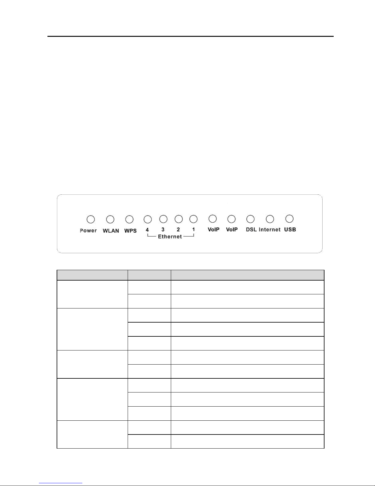
1.11 LED Status Description
1.11.1 LED Status
Indicator
Status
Description
Power
On Power is supplied.
Off Power is not supplied.
WLAN
On WLAN link is established.
Blinks WLAN traffic is flowing.
Off WLAN is disabled.
WPS
On WPS link is enabled.
Off WPS link is disabled.
Ethernet4/3/2/1
On LAN link is established and active.
Blinks LAN data is transmitting.
Off No LAN link.
VoIP
On VoIP phone is registered.
Blinks Phone is off-hook.
Page 14
10
Indicator
Status
Description
Off VoIP phone is not registered.
DSL
On DSL line is connected.
Blinks DSL line is transmitting.
Off DSL line is disconnected.
Internet Blinks DSL traffic is flowing.
USB
On USB connection is normal.
Blinks USB data is transmitting.
Off USB connection failed.
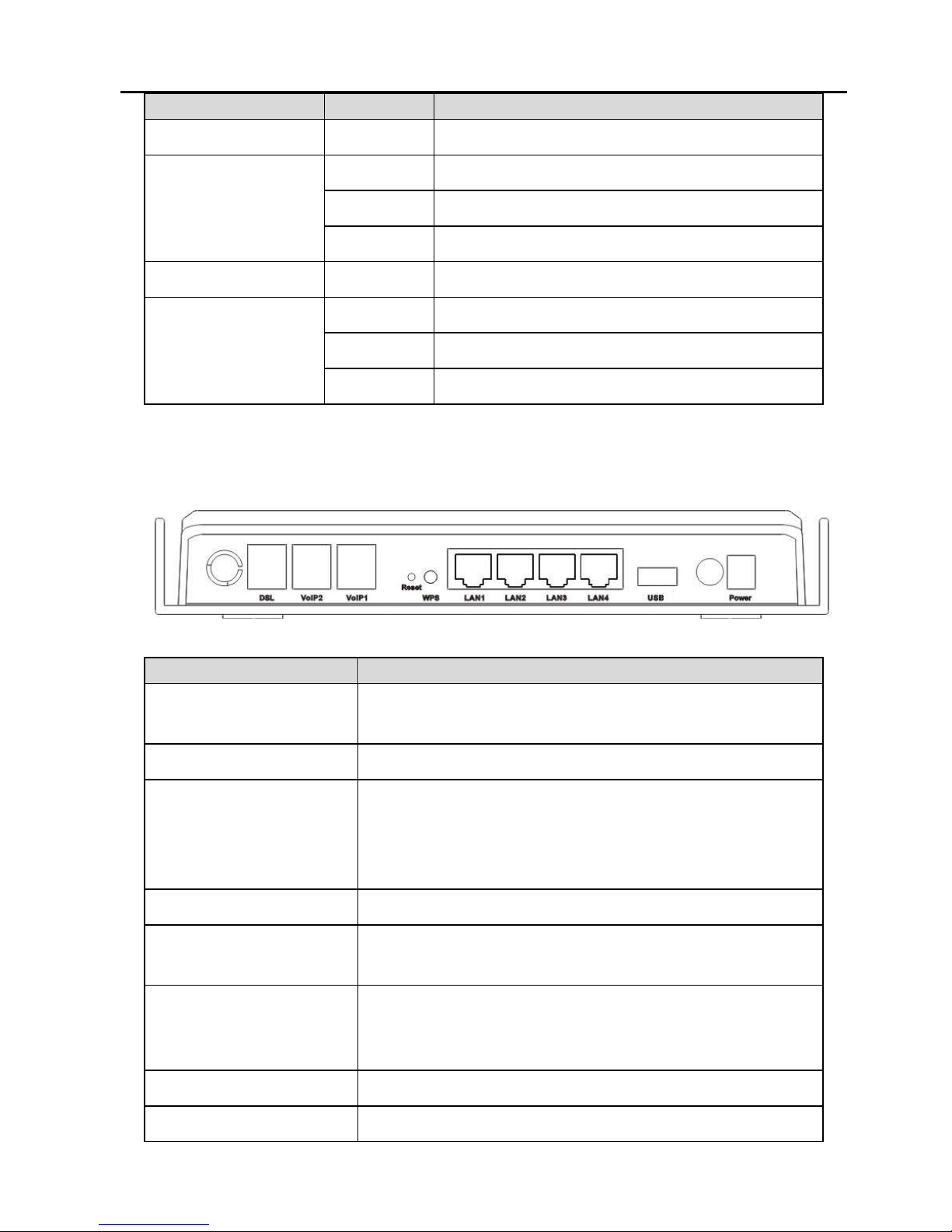
1.11.2 Rear Panel
Interface
Description
DSL
VDSL connector, for connecting to VDSL
telephone line.
VoIP1/2 Connect phones for VoIP application
Reset
Keep power on, put a thin needle in-to the
hole to press the button for about 1 second,
then the device restores to the factory default
configuration.
WPS WPS is enabled.
LAN 1/2/3/4
LAN interface, for connecting to a computer or
switch.
USB
USB host interface, connect to another USB
device to supply some value-added
application.
Switch Power switch.
Power Socket Plug in for power adaptor.
Page 15

11
2 Hardware Installation
The DSL router has three separate interfaces, an Ethernet LAN,
a wireless LAN and a VDSL (WAN) interface. Place the DSL
router in a location where it can be connected to various
devices as well as to a power source. The router should not be
located in places where it is exposed to moisture or excessive
heat. Ensure that cables and the power cord are placed safely
out of the way, so they do not create a tripping hazard. As with
any electrical appliance, observe common sense safety
procedures.
2.1 Choosing the Best Location for
Wireless Operation
Many environmental factors may affect the effective wireless
function of the DSL router. If this is the first time that you set up
a wireless network device, read the following information.
The access point can be placed on a shelf or desktop, ideally
you should be able to see the LED indicators in the front, as
you may need to view them for troubleshooting.
With a coverage area of up to 100 meters indoors and up to
300 meters outdoors, wireless LAN lets you access your
network from anywhere you want. However, the numbers of
walls, ceilings, or other objects that the wireless signals must
pass through limit signal range. Typical ranges vary depending
on types of materials and background RF noise in your home
or business. For optimum range and signal strength, use these
basic guidelines.
Keep the numbers of walls and ceilings to the minimum:
The signal emitted from wireless LAN devices can
penetrate through ceilings and walls. However, each wall
Page 16

12
or ceiling can reduce the range of wireless LAN devices by
1~30 meters. Position your wireless devices so that the
number of walls or ceilings obstructing the signal path is
minimized.
Consider the direct line between access points and
workstations:
A wall that is 0.5 meters thick, at a 45 degree angle
appears to be almost 1 meter thick. At a 2-degree angle, it
appears over 14 meters thick. Be careful to position
access points and client adapters, so the signal can travel
straight through (90º angle) a wall or ceiling for better
reception.
Building materials make a difference:
Buildings constructed using metal framing or doors can
reduce effective range of the device. If possible, position
wireless devices so that their signals can pass through
drywall or open doorways. Avoid positioning them in the
way that their signal must pass through metallic materials.
Poured concrete walls are reinforced with steel while
cinderblock walls generally have little or no structural steel.
Position the antenna for best reception:
Play around with the antenna position to check if signal
strength improves. Some adapters or access points allow
you to judge the strength of the signal.
Keep your product away (at least 1~2 meters) from
electrical devices:
Keep wireless devices away from electrical devices that
generate RF noise, such as microwave ovens, monitors,
electric motors, etc.
2.2 Connecting the VDSL Router
Step 1 See the following figure. Connect the DSL port of the
DSL router with a telephone cable.
Step 2 Connect the LAN port of the DSL router to the network
Page 17
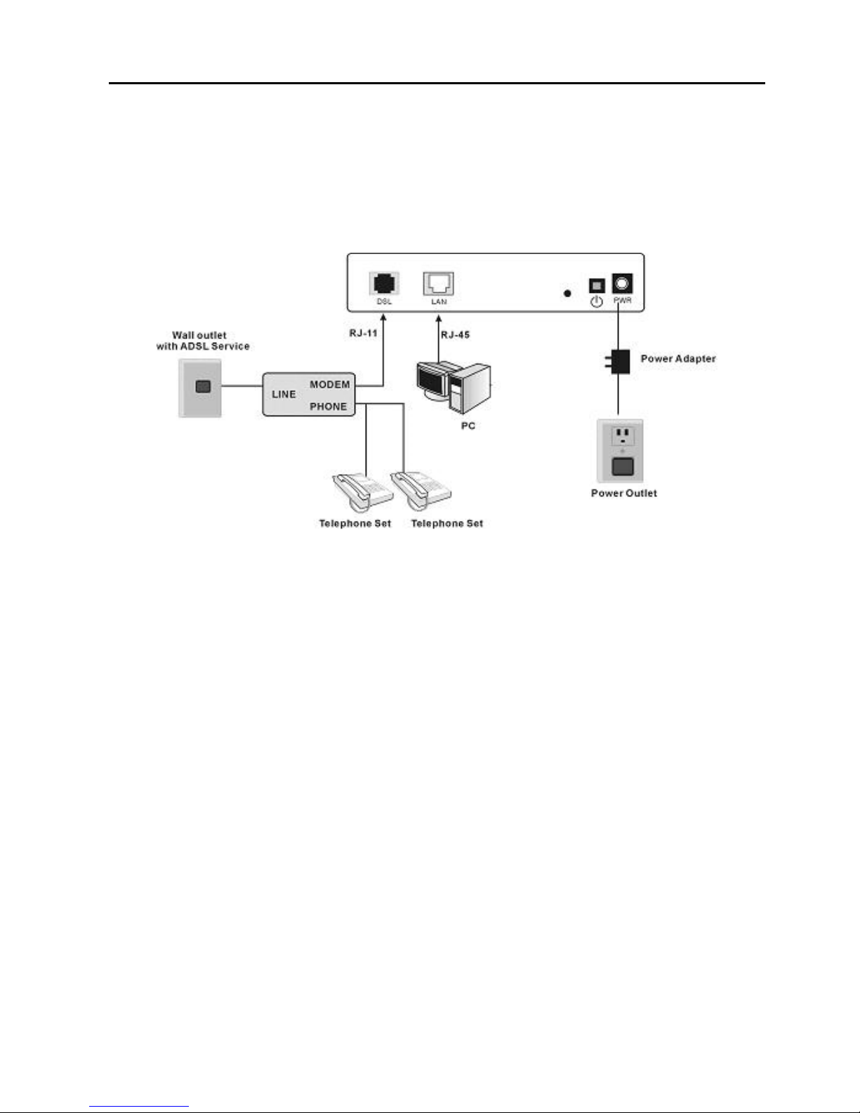
13
card of the PC via an Ethernet cable.
Step 3 Plug one end of the power adapter to the wall outlet
and connect the other end to the power port of the DSL
router.
The following figure displays the connection of the DSL router,
PC, and telephones.
2.3 Factory Reset Button
The router may be reset to the factory default settings by
pressing the reset button for a few seconds while the device is
powered on. Use a ballpoint or paperclip to gently push down
the reset button. Remember that this wipes out any settings
stored in the flash memory, including user account information
and LAN IP settings. The device settings are restored to the
following factory defaults: the IP address is 192.168.1.1,
subnet mask is 255.255.255.0, user name is admin, and
password is admin.
Page 18

Error! Use the Home tab to apply 标题 to the text that you want to appear
here.Error! Use the Home tab to apply 标题 to the text that you want to
appear here.
14
3 Connection
3.1 About DSL Router
DSL router is a scalable suite of software infrastructure and
technologies that original equipment manufacturers (OEMs)
require in order to bring residential gateways/IADs to market.
DSL router leverages a wide range of compelling
broadband-based applications and services and includes an
operating system, drivers, and remote management
capabilities. DSL router delivers a set of highly integrated
solutions required for homes and small companies, such as:
Optimized Linux 2.6 operating system
IP routing and bridging
Asynchronous transfer mode (ATM) and digital subscriber
line (DSL) support
Point-to-point protocol (PPP)
Network/port address translation (NAT/PAT)
Quality of service (QoS)
Wireless LAN security: WPA, 802.1x, RADIUS client
Universal plug-and-play
File server for network attached storage (NAS) devices
Web filtering
Carrier-level voice over IP (VoIP): SIP, MGCP, RTP
Management and control
– Web-based management (WBM)
– Simple network management protocol (SNMP)
– Command line interface (CLI)
– TR-069 WAN management protocol
– TR-064 LAN-side DSL CPE configuration
Remote update
System statistics and monitoring
Page 19
15
DSL router is targeted at the following platforms: DSL
Routers, wireless access points and bridge.
3.2 Setup
Connecting your computer or home network to the DSL router
is a simple procedure, varying slightly depending on the
operating system. This chapter guides you to seamlessly
integrate DSL router with your computer or home network. The
Windows default network settings dictate that in most cases the
setup procedure described as follows is unnecessary. For
example, the default DHCP setting in Windows 2000 is client,
requiring no further modification. However, it is advised to
follow the setup procedure described as follows to verify that all
communication parameters are valid and that the physical
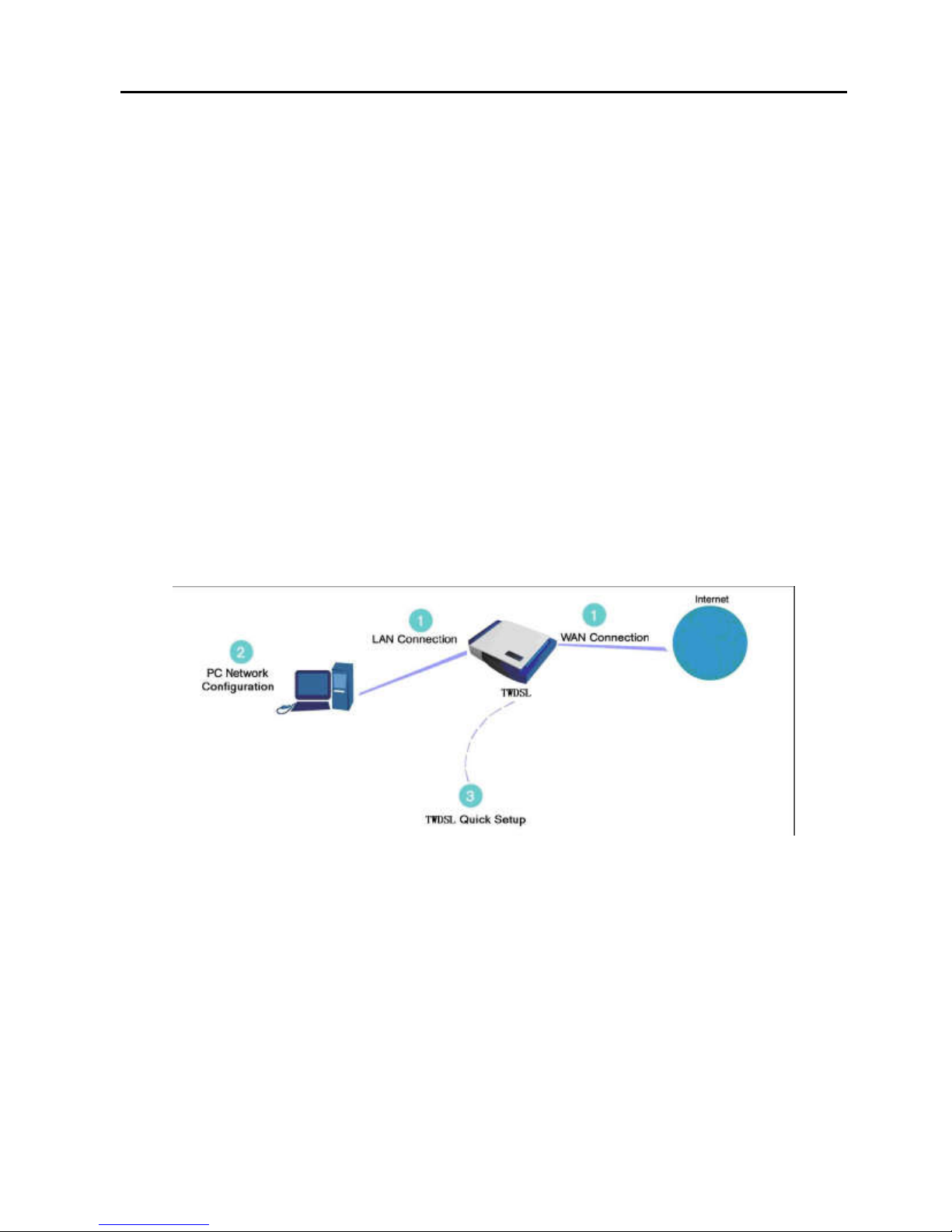
cable connections are correct. The setup procedure consists of
three consecutive configuration stages:
Figure 1
Hardware configuration
(1) Setting up WAN and LAN connections
(2) PC network configuration
(3) DSL router quick setup via Web-based management
3.2.1 Setting up WAN and LAN Connections
WAN Connection
Your connection to the Internet by DSL (VDSL/VDSL) DSL
Router connects its DSL socket to the wall socket by using a
Page 20

16
telephone cable. If it has an Ethernet socket for the wide area
network (WAN), connect it to the external DSL Router you have,
or to the Ethernet socket you might have, by using an Ethernet
cable.
LAN Connection
Your computer can connect to the gateway in various ways
(Ethernet, wireless, etc.), each requiring a different physical
connection. The most common type of connection is Ethernet,
with most platforms featuring four such ports. Use an Ethernet
cable to connect an Ethernet port of your DSL router and the
network card of your computer. Please refer to the
accompanying Installation Guide for additional information.
3.2.2 PC Network Configuration
Each network interface on the PC should either be configured
with a statically defined IP address and DNS address, or be
instructed to automatically obtain an IP address using the
network DHCP server. DSL router provides a DHCP server on
its LAN and it is recommended to configure your LAN to
automatically obtain its IP address and DNS server IP address.
The configuration principle is identical but should be carried out
differently on each operating system.
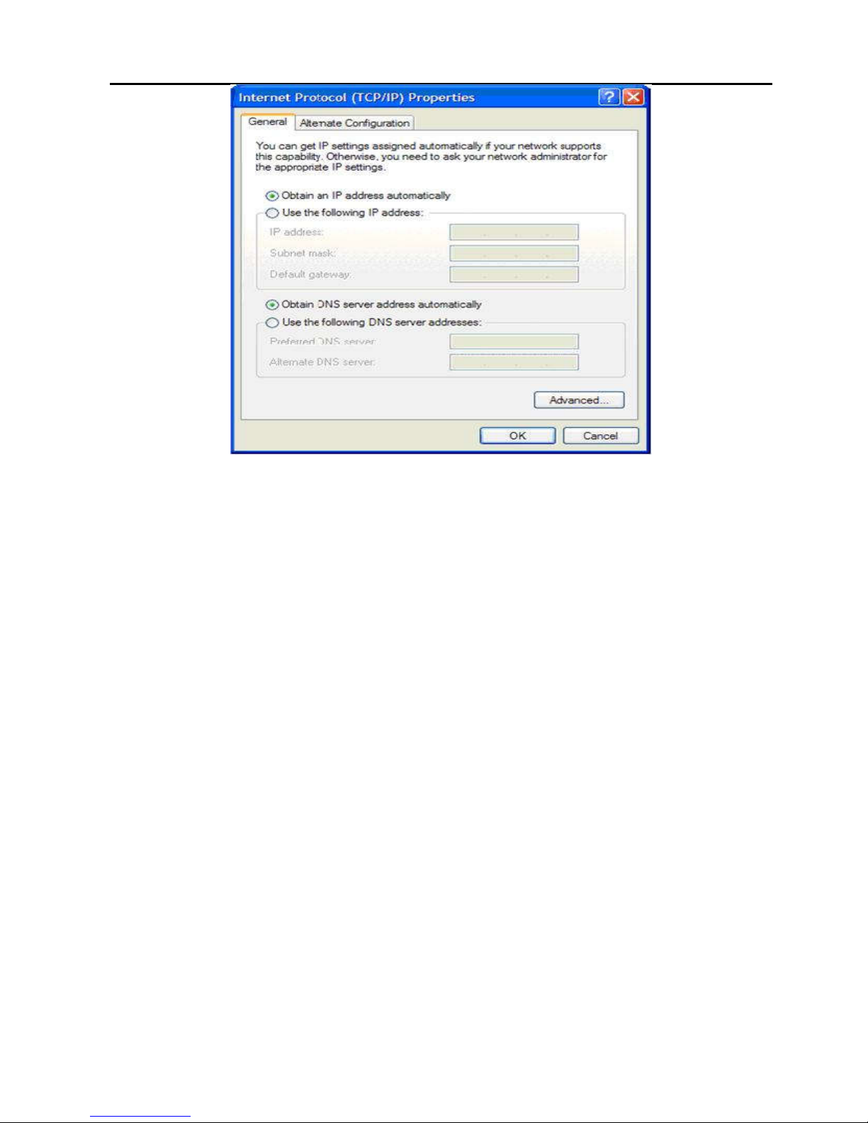
The following displays the TCP/IP Properties dialog box as it
appears on Windows XP.
Page 21
17
Figure 2 IP and DNS configuration
TCP/IP configuration instructions for all supported operating
systems are as follows.
Windows XP
Step 1 Choose Start > Control Panel > Access Network
Connections from the desktop.
Step 2 Right-click Ethernet Connection icon and choose
Properties.
Step 3 On General tab, select the Internet Protocol (TCP/IP)
component and click Properties.
Step 4 The Internet Protocol (TCP/IP) Properties page
appears.
Step 5 Select the Obtain an IP address automatically radio
button.
Step 6 Select the Obtain DNS server address automatically
radio button.
Step 7 Click OK to save the settings.
Windows 2000/98/Me
Step 1 Select Start > Control Panel > Network and Dialing
Page 22

18
Connections from the desktop.
Step 2 Right-click Ethernet connection icon and choose
Properties.
Step 3 Select Internet Protocol (TCP/IP) component and
click Properties.
Step 4 The Internet Protocol (TCP/IP) Properties page
appears.
Step 5 Select Obtain an IP address automatically radio
button.
Step 6 Select Obtain DNS server address automatically
radio button.
Step 7 Click OK to save the settings.
Windows NT
Step 1 Select Start > Control Panel > Network from the
desktop.
Step 2 On Protocol tab, select Internet Protocol (TCP/IP)
component and click Properties.
Step 3 On IP Address tab, select Obtain an IP address
automatically radio button.
Step 4 On DNS tab, verify that no DNS server is defined in the
DNS Service Search Order box and no suffix is
defined in the Domain Suffix Search Order box.
Linux
Step 1 Enter su at the prompt to log in to the system as a
super user.
Step 2 Enter ifconfig to display the network devices and
allocated IP addresses.
Step 3 Enter pump -i <dev>, where <dev> is the name of the
network device.
Step 4 Enter ifconfig again to view the newly allocated IP
address.
Step 5 Ensure that no firewall is active on this device.
Page 23

Error! Use the Home tab to apply 标题 to the text that you want to appear
here.Error! Use the Home tab to apply 标题 to the text that you want to
appear here.
19
4 Web-Based Management
This chapter describes how to use Web-based management of
the DSL router, which allows you to configure and control all of
DSL router features and system parameters in a user-friendly
GUI. This user-friendly approach is also implemented in the
WBM documentation structure, which is directly based on the
WBM structure. It is easy to navigate through both the WBM
and its documentation.
Page 24
20
Figure 3 Web-based management-home page
4.1 Logging In to the DSL Router
4.1.1 First-Time Login
When you log in to the DSL router for the first time, the login
wizard appears.
Step 1 Open the Web browser on your computer.
Step 2 Enter http://192.168.1.1 (default IP address of the DSL
router) in the address bar. The Login page appears.
Page 25
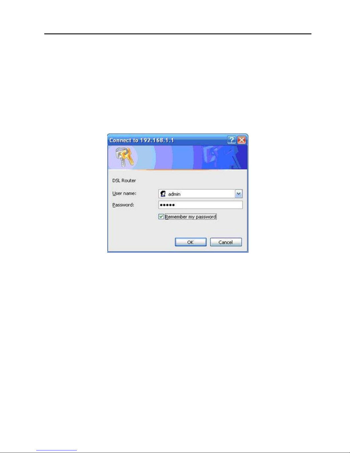
21
Step 3 Enter a user name and the password. The default user
name and password of the super user are admin and
admin. The user name and password of the common
user are user and user. You need not to enter the user
name and password again if you select the option
Remember my password. It is recommended to
change these default values after logging in to the DSL
router for the first time.
Step 4 Click OK to log in or click Cancel to exit the login page.
Figure 4 WBM login authentication
After logging in the DSL router as a super user, you can query,
configure, and modify all configurations, and diagnose the
system.
You need to reboot the DSL router to effect your modification or
configuration. In some cases, for example, after you modify the
PVC configuration, some modification, such as adding a static
route, takes effect at once and does not require DSL Router
reboot.
4.2 Quick Setup
Note: The Quick Setup menu is displayed only when no PVC
settings are available.
Page 26

22
The Quick Setup page mainly includes the following three
functions:
WAN interface setup
LAN interface setup
Wireless interface setup
Quick setup enables fast and accurate configuration of your
Internet connection and other important parameters. The
following sections describe these various configuration
parameters. Whether you configure these parameters or use
the default ones, click Next to enable your Internet connection.
When subscribing to a broadband service, you should be
aware of the method, by which you are connected to the
Internet. Your physical WAN device can be Ethernet, DSL, or
both. Technical information regarding the properties of your
Internet connection should be provided by your Internet service
provider (ISP). For example, your ISP should inform you
whether you are connected to the Internet using a static or
dynamic IP address, or which protocols such as PPPoA or
PPPoE, you are to use to communicate over the Internet.
4.2.1 WAN Interface Setup
During WAN interface setup, you can set up a PVC and its
properties:
VPI
VCI
QoS
Internet Connection Type
Encapsulation Mode
IGMP Service
NAT
4.2.1.1 Setting up VPI/VCI and QoS
After logging in to the DSL router, if no PVC is configured
previously and no default settings exist, the Quick Setup page
appears. This page contains some basic configuration needed
Page 27
23
by ATM PVC. The following introduction guides you through the
necessary steps to configure your DSL router.
According to your ISP instructions, specify the following
parameters:
VPI (Virtual Path Identifier): virtual path between two
points in an ATM network. The valid value range is from 0
to 255.
VCI (Virtual Channel Identifier): virtual channel between
two points in an ATM network. The valid value range is
from 32 to 65535 (1 to 31 are reserved for known
protocols).
Enable Quality Of Service: enabling QoS for a PVC
improves performance for selected classes of applications.
However, since QoS also consumes system resources,
the number of PVCs is reduced consequently. Use Quality
of Service in Advanced Setup to assign priorities for the
applications.
Figure 5 PVC and its QoS-configuration
For example, PVC 0/35 is to be modified and the default values
of QoS remain. In actual applications, you can modify them
according to your ISP’s instructions.
Page 28

24
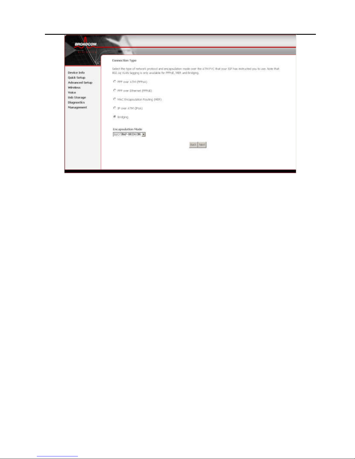
4.2.1.2 Selecting Internet Connection Type and
Encapsulation Mode
You can select your connection type from the following list.
Each connection type corresponds to several encapsulation
modes.
PPP over ATM (PPPoA)
PPPoA Encapsulation Mode:
– VC/MUX
– LLC/ENCAPSULATION
PPP over Ethernet (PPPoE)
PPPoE Encapsulation Mode:
– LLC/SNAP-BRIDGING
– VC/MUX
MAC Encapsulation Routing (MER)
MER Encapsulation Mode:
– LLC/SNAP-BRIDGING
– VC/MUX
IP over ATM (IPoA)
IPoA Encapsulation Mode:
– LLC/SNAP-ROUTING
– VC/MUX
Bridging
Bridging Encapsulation Mode:
– LLC/SNAP-BRIDGING
– VC/MUX
Page 29
25
Figure 6 Internet connection type and encapsulation mode
For example, set the connection type of PVC 0/35 to Bridging.
Select Bridging, and set Encapsulation Mode to
LLC/SNAP-BRIDGING (depending on the uplink equipment).
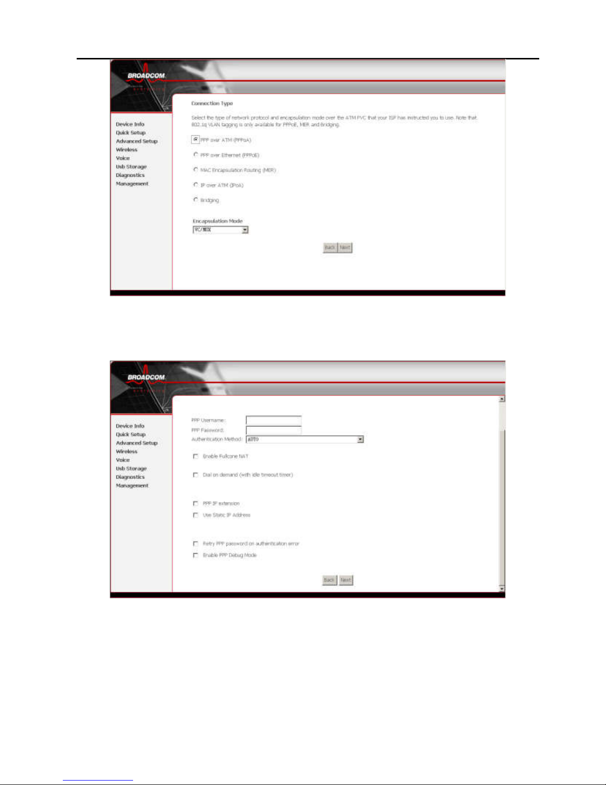
4.2.1.3 Internet Connection Type-PPP over ATM
(PPPoA)
Step 1 In the PVC and its QoS Configuration page,
configure a PVC and its QoS.
Step 2 In the Internet Connection Type and Encapsulation
Mode page, set the Connection Type to PPP over
ATM (PPPoA) and select the encapsulation mode.
Page 30
26
Figure 7 PPP over ATM (PPPoA)
Step 3 Click Next and the PPP Information Configuration
page appears.
Figure 8 PPP information configuration
Your ISP should provide you with the following information:
PPP username
PPP password
Authentication method
You can also select another service function as follows:
Page 31

27
Dial on demand (with idle timeout timer)
PPP IP extension
Use static IP address
Retry PPP password on authentication error
Enable PPP debug mode
Step 4 Click Next and the PPPoA IGMP and WAN Function
Configuration page appears.
To use IGMP service on PPPoA PVC, select Enable IGMP
Multicast check box.
Figure 9 PPPoA IGMP and WAN function configuration
4.2.1.4 Internet Connection Type-PPP over
Ethernet (PPPoE)
Step 1 In the PVC and its QoS Configuration page,
configure a PVC and its QoS.
Step 2 In the Internet Connection Type and Encapsulation
Mode page, set Connection Type to PPP over
Ethernet (PPPoE) and select the encapsulation mode.
Page 32

28
Figure 10 PPP over Ethernet (PPPoE)
Step 3 Click Next and the PPP Information Configuration
page appears.
Figure 11 PPP information configuration
Your ISP should provide you with the following information:
PPP username
PPP password
Authentication method
You can also select another service function as follows:
Page 33

29
Dial on demand (with idle timeout timer)
PPP IP extension
Use static IP address
Retry PPP password on authentication error
Enable PPP debug mode
Step 4 Click Next and PPPoE IGMP and WAN Function
Configuration page appears.
To use IGMP service on PPPoA PVC, select the Enable IGMP
Multicast check box.
Figure 12 PPPoE IGMP and WAN function configuration
4.2.1.5 Internet Connection Type-MAC
Encapsulation Routing (MER)
Step 1 In the PVC and its QoS Configuration page,
configure a PVC and its QoS.
Step 2 In the Internet Connection Type and Encapsulation
Mode page, set the Connection Type to MAC
Encapsulation Routing (MER) and select the
encapsulation mode.
Page 34

30
Figure 13 MAC encapsulation routing (MER)
Step 3 Click Next and the WAN IP Configuration page
appears.
Figure 14 WAN IP configuration
You can select the service function as follows:
Obtain an IP address automatically (use DHCP to obtain
WAN IP)
Use the following IP address (use static WAN IP)
Obtain default gateway automatically (use DHCP to obtain
Page 35

31
gateway IP)
Use the following default gateway (use static gateway IP)
Obtain DNS server addresses automatically (use DHCP to
obtain DNS server IP)
Use the following DNS server addresses (use static DNS
server IP)
Step 4 Click Next and the MER IGMP and WAN Function
Configuration page appears.
To use IGMP service on MER PVC, select the Enable IGMP
Multicast check box.
In the MER mode, you can configure the following functions:
Enable NAT.
Enable Fullcone NAT. (After enabling NAT, Enable
Fullcone NAT check box appears.)
Enable Firewall.
Figure 15 MER IGMP and WAN function configuration
4.2.1.6 Internet Connection Type-IP over ATM
(IPoA)
Step 1 In the PVC and its QoS Configuration page,
configure a PVC and its QoS.
Step 2 In the Internet Connection Type and Encapsulation
Page 36

32
Mode page, set the Connection Type to IP over ATM
(IPoA) and select the encapsulation mode.
Figure 16 IP over ATM (IPoA)
Step 3 Click Next and the WAN IP Configuration page
appears.
Figure 17
WAN IP configuration
You can select the service function as follows:
Use the following IP address (static WAN IP)
Use the following default gateway (static gateway IP)
Page 37

33
Use the following DNS server addresses (static DNS
server IP)
Step 4 Click Next and the IPoA IGMP and WAN Function
Configuration page appears.
To use IGMP service on IPoA PVC, select the Enable IGMP
Multicast check box.
In the MER mode, you can configure the following functions:
Enable NAT.
Enable Fullcone NAT.
Enable Firewall.
Figure 18 IPoA IGMP and WAN function configuration
4.2.1.7 Internet Connection Type-Bridging
Step 1 In the PVC and its QoS Configuration page,
configure a PVC and its QoS.
Step 2 In the Internet Connection Type and Encapsulation
Mode page, set the Connection Type to Bridging and
select the encapsulation mode.
Page 38

34
Figure 19 Bridging
Step 3 Click Next and the Bridging service Configuration
page appears.
Figure 20 Bridging service configuration
4.2.2 LAN Interface Setup
The LAN interface setup page is as follows.
Page 39

35
Figure 21 LAN interface setup
4.2.3 Wireless Interface Setup
Enable Wireless: select or deselect the check box to enable or
disable wireless connection.
SSID: it is the network name shared among all points in a
wireless network. The SSID must be identical for all points in
the wireless network. It is case-sensitive and must not exceed
32 characters (use any character on the keyboard).
Page 40

36
Figure 22 Wireless setup
4.2.4 WAN Setup Summary
In WAN setup summary, you can view the following properties
of the added PVC:
PORT/VPI/VCI
Connection Type:
Service Name:
Service Category:
IP Address:
Service State:
NAT
Firewall
IGMP Multicast
Quality of Service
Figure 23 WAN setup summary
Click Save to save the settings. To make any modifications,
click Back. Then, click Save/Reboot and the following page
appears.
Note: You need to reboot to activate this WAN page and further
configure services in this page, and it takes about two
Page 41

37
minutes to reboot.
Figure 24 DSL router reboot
4.2.5 Quick Setup Completion
After the previous setup, you can immediately start using your
gateway to:
Share a broadband connection among multiple users
(HTTP, FTP, Telnet and NetMeeting) and among all of the
computers connected to your home network.
Build a home network by connecting additional PCs and
network devices to the gateway.
Control network parameters, including DHCP, DNS, and
WAN settings.
View network status, traffic statistics, system log, and so
on.
Allow access from the Internet to games and other
services provided by computers in the home network.
Prohibit computers in the home network from accessing
selected services on the Internet.
Block access to specific Internet websites from your home
network.
Page 42

38
If your gateway is equipped with multiple LAN ports, you can
connect additional devices directly to the gateway. Otherwise,
connect a hub or switch to the LAN port, to which you can
connect additional devices. In both cases, configure newly
connected devices to automatically obtain IP address as
previously described.
4.3 DSL Router Device information
Click Device Info and you can view the following information:
Summary
WAN
Statistics
Route
ARP
DHCP
Figure 25 Device Info menu
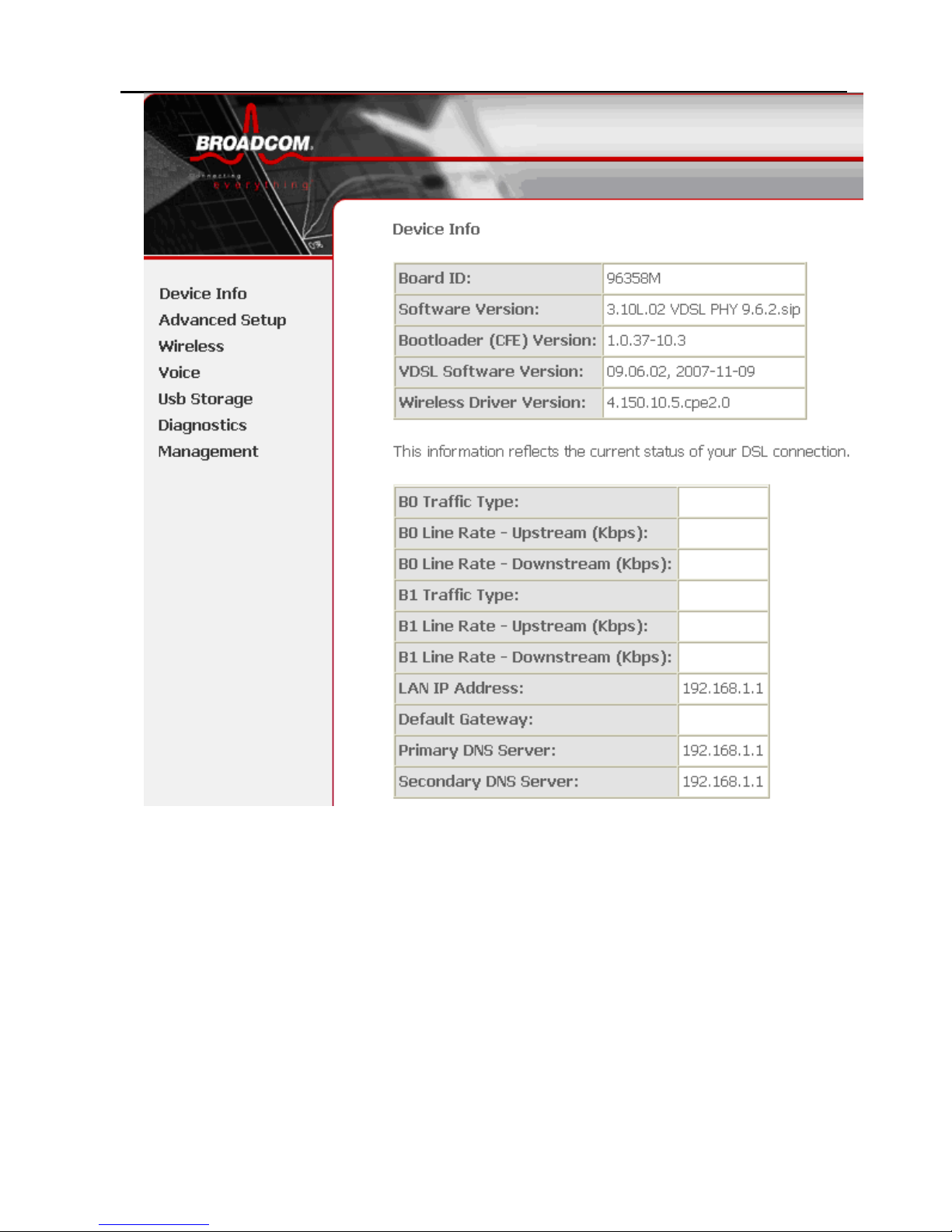
4.3.1 Summary of Device information
This page contains the following information:
Board ID
Software version
Bootloader (CFE) version
VDSL Software Version
Wireless driver version
B0 Traffic Type
Page 43

39
B0 Line Rate – Upstream(kbps)
B0 Line Rate –Downstream(kbps)
B1 Traffic Type
B1 Line Rate – Upstream(kbps)
B1 Line Rate –Downstream(kbps)
LAN IP address: the management IP address
Default gateway: in the bridging mode, there is no
gateway. In other modes, it is the address of the uplink
equipment, for example, PPPoE/PPPoA.
DNS server address: In the PPPoE/PPPoA mode, it is
obtained from the uplink equipment. In the bridging mode,
there is no DNS server address and you can manually
enter the information.
Page 44

40
Figure 26 Summary of device information
4.3.2 WAN Interface Information
Click WAN and the following page appears. The WAN Info
page displays the status.
This page contains the following informations for each WAN
connection:
Port/VPI/VCI
VLAN
Connection ID
Category
Service
Interface
Protocol
IGMP
QoS
State
Status
IP address
Figure 27 WAN interface info
4.3.3 Statistics
This page contains the following four parts:
Statistics of LAN
Page 45

41
Statistics of WAN
Statistics of ATM
Statistics of VDSL
4.3.3.1 Statistics of LAN
Select Statistics > LAN and the following page appears. You
can query information of packets recevied at the Ethernet and
wireless interfaces. Click Reset Statistics to restore the values
to zero and recount them.
The LAN side interface includes wireless device. You can view
the following information of each device:
Interface
Received
– Bytes: bytes of received
– Pkts: packets of received
– Errs: error packets of received
– Drops: drop packets of received
Transmitted
– Bytes: bytes of transmitted
– Pkts: packets of transmitted
– Errs: error packets of transmitted
– Drops: drop packets of transmitted
Page 46

42
Figure 28 Statistics of LAN
4.3.3.2 Statistics of WAN
Select Statistics > WAN and the following page appears. You
can query information of packets recevied at the WAN
interfaces. Click Reset Statistics to restore the values to zero
and recount them.
Information is as follows:
Service
VPI/VCI
Protocol
Interface
Received
– Bytes: bytes of received
– Pkts: packets of received
– Errs: error packets of received
Page 47

43
– Drops: drop packets of received
Transmitted
– Bytes: bytes of transmitted
– Pkts: packets of transmitted
– Errs: error packets of transmitted
– Drops: drop packets of transmitted
Figure 29 Statistics of WAN
4.3.3.3 Statistics of ATM
Select Statistics > ATM and the following page appears. You
can query information of packets recevied at the ATM
interfaces. Click Reset to restore the values to zero and
recount them.
The information is as follows:
ATM Interface Statistics:
– Rx Low Priority Code Violations
– Rx Low Priority Code Violations
– Rx Low Priority Code Violations
– Rx High Priority Overflow
Page 48

44
Figure 30 Statistics of ATM
4.3.3.4 Statistics of VDSL
Select Statistics > VDSL and the following page appears.
If the DSL line is activated, the following page appears.
Page 49

45
Figure 31 Statistics of VDSL
You can view the following information of the VDSL line:
Mode: T1.413, VDSL 2.
Status: Link Down, No Defect, Training
Rate (Kbps): B0, B1 Upstream Line Rate, Downstream
Page 50

46
Line Rate.
Click Close at the bottom to restore the values to zero and
recount them.
4.3.4 Route Table Information
Click Route and the following page appears. You can view the
following information of each route in the route table:
Destination
Gateway
Subnet Mask
Flag
Metric
Service
Interface
Page 51

47
Figure 32 Route table
4.3.5 ARP Table Information
Click ARP and the following page appears. You can query the
MAC and IP address information of the equipment attached to
the DSL Router and the information includes the following:
IP address
Flags
HW address
Device
Figure 33 ARP table
4.3.6 DHCP IP Lease Information
Click DHCP and the following page appears. You can query the
IP address assignment for MAC address at the LAN side of the
DSL router and obtain the IP Address from the DHCP server
through Ethernet and wireless in the DSL router.
The information of each lease item includes the following:
Hostname
MAC Address
IP Address
Expires In: time that the device leases the IP Address for
Page 52

48
the MAC Address
Figure 34 DHCP leases list
4.4 Advanced Setup
Click Advanced Setup and the Advanced system setup
page appears. The information is as follows:
WAN: wide area network interface
LAN: local area network interface
NAT: network address translation
Security
Quality of Service
Routing
DNS
DSL
Print Server
Port Mapping
Certificate
Advance Setup is key to DSL Router configuration.
Page 53

49
Figure 35 Advance setup menu
4.4.1 WAN Configuration
Select Advanced Setup > WAN and two circumstances may
occur. In this page, you can perform the following operations:
Add
Edit
Remove
Save/Reboot
Figure 36 WAN configuration
Click Add. The configure page displayed contains the following
information:
Add PVC
VLAN of PVC
– Quality of Service PVC
– Service category
Add PPPoE PVC
Page 54

50
– PPP IP extension
Add PPPoA PVC
Add MER PVC
Add Bridge PVC
Add IPoA PVC
Figure 37 PVC and its QoS configuration
This page is the same as the Quick Setup page. For
configuration of the PVC and its QoS, refer to the configuration
in Quick Setup page. If the DSL Router is already configured,
click WAN and the following page appears.
Figure 38 PPPoE configuration
Step 1 To modify the parameters of an existing PVC, click
Edit.
Page 55

51
Step 2 To add an ATM PVC, click Add.
Step 3 To delete a PVC, select the Remove check box in the
table and click Remove.
Step 4 Click Save/Reboot to apply the changes and reboot
the DSL Router.
Note: After a PVC is deleted or modified, the system must be
rebooted. Otherwise, the modification does not take
effect.
The procedure for adding a PVC is described as follows.
4.4.1.1 Adding a PPPoE PVC
This section describes the procedure for adding PVC 8/35
(PPPoE mode).
Step 1 Click Add and the following page appears. In this page,
you can modify VPI/VCI, service category, and QoS.
Figure 39 PVC and its QoS configuration
VPI (Virtual Path Identifier): virtual path between two
points in an ATM network. Its valid value range is from 0 to
255.
VCI (Virtual Channel Identifier): virtual channel between
two points in an ATM network. Its valid value range is from
32 to 65535 (1 to 31 are reserved for known protocols).
Page 56

52
VLAN Mux: Config VlanID over a single pvc
Service Category: UBR Without PCR, UBR With PCR,
CBR, Non Realtime VBR and Realtime VBR.
Enable Quality Of Service: enable or disable QoS.
In this example, PVC 8/35 is to be modified and the default
values of service category and QoS remain. In actual
applications, you can modify them as required.
After proper modifications, click Next and the following page
appears.
Step 2 In this page, you can modify the Internet connection
type and encapsulation mode.
Figure 40 Internet connection type and encapsulation mode
Change the connection type of PVC 8/35 to PPP over
Ethernet (PPPoE) and set the Encapsulation Mode to
LLC/SNAP-BRIDGING (according to the uplink equipment).
Page 57

53
Figure 41 PPP over Ethernet (PPPoE)
Click Next and the following page appears.
Step 3 In this page, you can modify the PPP user name, PPP
password, and authentication method.
Page 58

54
Figure 42 PPP information and other functions
PPP Username: the correct user name that your ISP provides
to you.
PPP Password: the correct password that your ISP provides
to you.
PPPoE Service Name: if your ISP provides it to you, please
enter it. If not, do not enter any information.
Authentication Method: the value can be AUTO, PAP, CHAP,
or MSCHAP. Usually, you can select AUTO.
Dial on demand (with idle timeout timer): if this function is
enabled, you need to enter the idle timeout time. Within the
Page 59

55
preset minutes, if the DSL Router does not detect the flow of
the user continuously, the DSL Router automatically stops the
PPPoE connection. Once it detects the flow (like access to a
Web page), the DSL Router restarts the PPPoE dial-up.
If this function is disabled, the DSL Router performs PPPoE
dial-up all the time. The PPPoE connnection does not stop,
unless the DSL Router is powered off and DSLAM or uplink
equipment is abnormal.
PPP IP extension: if this function is enabled, the WAN IP
address obtained by the DSL Router through built-in dial-up
can be directly assigned to the PC being attached to the DSL
Router (at this time, the DSL Router connects to only one PC).
From the aspect of the PC user, the PC dials up to obtain an IP
address. But actually, the dial-up is done by the DSL Router.
If this function is disabled, the DSL Router itself obtains the
WAN IP address.
Use Static IP Address: if this function is disabled, the DSL
Router obtains an IP address assigned by an uplink equipment
such as BAS, through PPPoE dial-up.
If this function is enabled, the DSL Router uses this IP address
as the WAN IP address.
After entering the PPP user name and password, click Next
and the following page appears.
In this page, you can modify the service name, and enable or
disable the IGMP multicast and WAN service.
Page 60

56
Figure 43 PPPoE IGMP and WAN service
IGMP Multicast: IGMP proxy. For example, if you wish that the
PPPoE mode supports IPTV, enable this function.
WAN Service: enable it unless you do not want to active the
PVC.
Click Next and the following page appears. This page shows
all the configuration. You can view the default values of NAT
enabled and Firewall enabled.
Page 61

57
Figure 44 PPPoE setup summary
To save the settings, click Save. To make any modifications,
click Back. After you click Save, the following page appears.
Note: You need to reboot the DSL Router to activate this WAN
interface and further configure services in this interface.
Page 62

58
Figure 45 PPPoE setup-completed
4.4.1.2 PPPoE PVC Network Application
Description
In this example, the DSL Router is connected to the DSLAM
through PVC 8/35 and the access mode is the built-in
PPPoE+NAT. The encapsulation of the BRAS downlink port is
PPP over Ethernet, the authentication is AUTO, the IP address
is 136.1.1.1, the IP pool is 136.1.1.*, and the IP address of
uplink port is 10.61.92.157. The IP of the WAN port on the DSL
Router is dynamically assigned by BRAS through the built-in
PPPoE dial-up. The PC attached to the DSL Router is assigned
with a private IP address (within the same segment as the
management IP of the DSL Router). The NAT function of the
DSL Router is enabled and the private address of the PC is
translated to the public address 136.1.1 .* (2~254) dynamically
assigned by BRAS for accessing ISP.
The IP address of the PC can be fixed (as in this example) or
assigned through DHCP server of the DSL Router. If it is
assigned by the DHCP server, the DHCP functions of the DSL
Router must be enabled. The IP address of the DHCP address
pool is 192.168.1.* (2~254). The functions are enabled by
default and at the same time the PC is configured to obtain IP
and DNS addresses dynamically.
Page 63

59
Setting Procedure
Step 1 Open the Internet browser and enter 192.168.1.1 in the
address bar to log in to the DSL Router.
Step 2 Choose Advanced Setup > WAN and click Add.
Step 3 In the
ATM PVC Configuration
page, set VPI/VCI to 8/35
and click Next.
Step 4 In the Connection Type page, select PPP over
Ethernet (PPPoE) and set the Encapsulation Mode
to LLC/SNAP-BRIDGING, and then click Next.
Step 5 In the PPP User name and Password page, enter the
user name and password provided by your ISP. Then,
click Next.
Step 6 In the Enable IGMP Multicast and WAN Service page,
keep the default settings and click Next.
Step 7 Confirm the network configuration and ensure that all
settings are consistent with the data provided by your
ISP. Then, click Save.
Step 8 Click Save/Reboot to apply the changes and reboot
the DSL Router.
You can also modify the PVC 8/35. To modify the LAN IP
address and DHCP server information, set in LAN in
Advanced Setup.
After the dial-up is successful, the DSL Router obtains the IP
address at the WAN-side port ppp_8_35_1.
Choose Device Info > Route and the route table is as follows:
Page 64

60
4.4.1.3 PPPoE PVC IP Extension Mode
Description
In this example, the DSL Router is connected to the DSLAM
through PVC 8/35; the PPPoE is located between the WAN
interface of the DSL Router and BRAS. The encapsulation of
the downlink interface of BRAS is PPP over Ethernet, the
authentication is AUTO, the IP address is 10.28.106.200, the IP
pool is 10.28.106.*, and the IP address of the uplink interface is
10.61.92.157.
The WAN interface of the DSL Router obtains the IP address
that is dynamically assigned by BRAS through its built-in
PPPoE dial-up. The DSL Router assigns this public IP address
to the PC (configured as Obtain an IP address automatically)
attached to it in the DHCP mode. At this time, the NAT does not
take effect. From the aspect of the user, the DSL Router seems
works in the Bridging mode.
In some cases, this function is named zero installation PPP
bridge (ZIPB) mode.
Setting Procedure
Step 1 Open the Internet browser and enter 192.168.1.1 in the
address bar to log in to the DSL Router.
Step 2 Select Advanced Setup > WAN and click Add.
Page 65

61
Step 3 In the ATM PVC Configuration page, set VPI/VCI to
8/35 and click Next.
Step 4 In the Connection Type page, select PPP over
Ethernet (PPPoE) and set the Encapsulation Mode to
LLC/SNAP-BRIDGING, and then click Next.
Step 5 In the PPP User name and Password page, enter the
user name and password provided by your ISP.
IMPORTANT: Select Enable PPP IP extension.
Step 6 Click Next.
Step 7 In the Enable IGMP Multicast and WAN Service page,
keep the default settings and click Next.
Step 8 Confirm the network configuration and ensure that all
settings are consistent with the data provided by your
ISP. Then, click Save.
Step 9 Click Save/Reboot to apply the changes and reboot
the DSL Router.
Modify the LAN IP address in LAN in Advanced Setup.
After the PPPoE dial-up which is built in the DSL Router is
successful, the IP address 10.28.106.82 is obtained.
4.4.1.4 Adding a PPPoA PVC
This section describes the procedure for adding PVC 1/35
(PPPoA mode).
Click Add and the following page appears.
In this page, you can modify VPI/VCI, service category, and
QoS.
Page 66

62
Figure 46 PVC and its QoS configuration
VPI (Virtual Path Identifier): virtual path between two points in
an ATM network. Its valid value range is from 0 to 255.
VCI (Virtual Channel Identifier): virtual channel between two
points in an ATM network. Its valid value range is from 32 to
65535 (1 to 31 are reserved for known protocols).
VLAN Mux: Config VlanID over a single pvc
Service Category: UBR Without PCR, UBR With PCR, CBR,
Non Realtime VBR and Realtime VBR.
Enable Quality of Service: enable or disable QoS.
In this example, PVC 8/35 is to be modified and the default
values of service category and QoS remain. In actual
applications, you can modify them as required.
After proper modifications, click Next and the following page
appears. In this page, you can modify the Internet connection
type and encapsulation mode.
Page 67

63
Figure 47 Internet connection type and encapsulation mode
Change the connection type of PVC 1/35 to PPP over ATM
(PPPoA) and set the Encapsulation Mode to VC/MUX
(according to the uplink equipment).
Figure 48 PPP over ATM (PPPoA)
Click Next and the following page appears. In this page, you
can modify the information including PPP user name, PPP
password, and authentication method.
Page 68

64
Figure 49 PPP information and other functions
PPP Username: the correct user name that your ISP provides
to you.
PPP Password: the correct password that your ISP provides
to you.
Authentication Method: the value can be AUTO, PAP, CHAP,
or MSCHAP. Usually, you can select AUTO.
Dial on demand (with idle timeout timer): if this function is
enabled, you need to enter the idle timeout time. Within the
preset minutes, if the DSL Router does not detect the flow of
the user continuously, the DSL Router automatically stops the
PPPoE connection. Once it detects the flow (like access to a
Web page), the DSL Router restarts the PPPoE dial-up.
If this function is disabled, the DSL Router performs PPPoE
dial-up all the time. The PPPoE connnection does not stop,
unless the DSL Router is powered off and DSLAM or uplink
equipment is abnormal.
PPP IP extension: if this function is enabled, the WAN IP
address obtained by the DSL Router through built-in dial-up
can be directly assigned to the PC being attached to the DSL
Page 69

65
Router (at this time, the DSL Router connects to only one PC).
From the aspect of the PC user, the PC dials up to obtain an IP
addres. But actually, the dial-up is done by the DSL Router.
If this function is disabled, the DSL Router itself obtains the
WAN IP address.
Use Static IP Address: if this function is disabled, the DSL
Router obtains an IP address assigned by an uplink equipment
such as BAS, through PPPoE dial-up.
If this function is enabled, the DSL Router uses this IP address
as the WAN IP address.
After entering the PPP user name and password, click Next
and the following page appears.
In this page, you can modify the service name, and enable or
disable the IGMP multicast and WAN service.
Figure 50 PPPoA IGMP and WAN service
IGMP Multicast: IGMP proxy. For example, if you wish that the
PPPoA mode supports IPTV, please enable this function.
WAN Service: enable it, unless you do not want to active the
PVC.
Click Next and the following page appears.
This page shows all the configuration. You can view the default
values of NAT enabled and Firewall enabled.
Page 70

66
Figure 51 PPPoA setup summary
To save the settings, click Save. To make any modifications,
click Back. After you click Save, the following page appears.
Note: You need to reboot the DSL Router to activate this WAN
interface and further configure services in this interface.
Page 71

67
Figure 52 PPPoA setup-completed
4.4.1.5 PPPoA PVC Network Application
Description
In this example, the DSL Router is connected to the DSLAM
through PVC 1/35 and the access mode is the built-in
PPPoA+NAT. The encapsulation of the BRAS downlink port is
PPP over ATM, the authentication is AUTO, the IP address is
10.28.106.200, the IP pool is 10.28.106.*, and the IP address
of uplink port is 10.61.92.157. The IP of the WAN port on the
DSL Router is dynamically assigned by BRAS through the
built-in PPPoA dial-up. The PC attached to the DSL Router is
assigned with a private IP address (within the same segment
as the management IP of the DSL Router). The NAT functions
of the DSL Router is enabled and the private address of the PC
is translated to the public address 10.28.106.* (2~254)
dynamically assigned by BRAS for accessing ISP.
The IP address of the PC can be fixed (as in this example) or
assigned through DHCP server of the DSL Router. If it is
assigned by the DHCP server, the DHCP functions of the DSL
Router must be enabled. The IP address of the DHCP address
pool is 192.168.1.* (2~254). The functions are enabled by
default and at the same time the PC is configured to obtain IP
and DNS addresses dynamically.
Page 72

68
Setting Procedure
Step 1 Open the Internet browser and enter 192.168.1.1 in the
address bar to log in to the DSL Router.
Step 2 Select Advanced Setup > WAN and click Add.
Step 3 In the
ATM PVC Configuration
page, set VPI/VCI to 1/35
and click Next.
Step 4 In the Connection Type page, select PPP over ATM
(PPPoA) and set the Encapsulation Mode to VC MUX,
and then click Next.
Step 5 In the PPP User name and Password page, enter the
user name and password provided by your ISP. Then,
click Next.
Step 6 In the Enable IGMP Multicast and WAN Service page,
keep the default settings and click Next.
Step 7 Confirm the network configuration and ensure that all
settings are consistent with the data provided by your
ISP. Then, click Save.
Step 8 Click Save/Reboot to apply the changes and reboot
the DSL Router.
4.4.1.6 Adding an MER PVC
This section describes the procedure for adding PVC 2/35
(MER mode).
Click Add and the following page appears.
Page 73

69
Figure 53 PVC and its QoS configuration
In this page, you can modify VPI/VCI, service category and
QoS.
VPI (Virtual Path Identifier): the virtual path between two
points in an ATM network, and its valid value is from 0 to 255.
VCI (Virtual Channel Identifier): virtual channel between two
points in an ATM network. Its valid value range is from 32 to
65535 (1 to 31 are reserved for known protocols).
VLAN Mux: Config VlanID over a single pvc
Service Category: UBR Without PCR, UBR With PCR, CBR,
Non Realtime VBR and Realtime VBR.
Enable Quality Of Service: enable or disable QoS.
In this example, PVC 2/35 is to be modified and the default
values of service category and QoS remain. In actual
applications, you can modify them as required.
After proper modifications, click Next and the following page
appears.
In this page, you can modify the Internet connection type and
encapsulation mode.
Page 74

70
Figure 54 Internet connection type and encapsulation mode
Change the connection type of PVC 2/35 to MAC
Encapsulation Routing (MER) and set the Encapsulation
Mode to LLC/SNAP-BRIDGING (according to the uplink
equipment).
Figure 55 MAC encapsulation routing (MER)
Click Next and the following page appears. In this page, you
can modify the WAN IP address, default gateway, and DNS
server settings.
Page 75

71
Figure 56 MER WAN IP configuration
Obtain an IP address automatically: the DSL Router obtains
a (WAN) IP address automatically and at this time it enables
DHCP client functions. The WAN IP address is obtained from
the uplink equipment like BAS, and the uplink equipment is
required to enable the DHCP server functions.
Use the following IP address: if you want to manually enter
the WAN IP address, select this check box and enter the
information in the field.
WAN IP Address: enter the IP address of the WAN interface
provided by your ISP.
WAN Subnet Mask: enter the subnet mask concerned to the
IP address of the WAN interface provided by your ISP.
Obtain Default Gateway automatically: obtain the IP address
of the default gateway assigned by the uplink equipment such
as BAS.
Use the following Default Gateway: if you want to manually
enter the IP address of the default gateway, select this check
box and enter the information in the fields.
Use IP Address: enter the gateway of the WAN interface
provided by your ISP.
Page 76

72
Use WAN Interface: as to BAS equipment, it is the IP address
of the downlink interface.
Obtain DNS server address automatically: to obtain the IP
address of the DNS server assigned by the uplink equipment
such as BAS.
Use the following DNS server addresses: If you want to
manually enter the IP address of the DNS server, select this
check box and enter the information in the fields.
Primary DNS server: enter the IP address of the primary DNS
server.
Secondary DNS server: enter the IP address of the secondary
DNS server provided by your ISP.
After proper modifications, click Next and the following page
appears.
In this page, you can modify the service name, and enable or
disable the NAT, firewall, IGMP multicast, and WAN service.
Figure 57 MER IGMP and WAN service
Enable NAT: select it to enable the NAT functions of the DSL
Router. If you do not want to enable NAT and wish the DSL
Router user to access the Internet normally, you must add a
route on the uplink equipment. Otherwise, the access to the
Internet fails. Normally, NAT should be enabled.
Page 77

73
Enable Firewall: enable or disable IP filtering.
IGMP Multicast: IGMP proxy. If you wish that the MER mode
supports IPTV, enable this function.
WAN Service: enable it, unless you do not want to activate the
PVC.
Click Next and the following page appears. This page shows
all the configuration.
Figure 58 MER setup summary
To save the settings, click Save. To make any modifications,
click Back. After you click Save, the following page appears.
Note: You need to reboot the DSL Router to activate this WAN
interface and further configure services in this interface.
Page 78

74
Figure 59 MER setup completed
4.4.1.7 MER PVC Network Application
Description
In this example, the DSL Router is connected to the DSLAM
through PVC 2/35 and the access mode is the MER+NAT. The
downlink interface of BRAS is encapsulated in 1483B, the IP
address is 10.28.108.1 and the DHCP server is enabled, the
address pool is 10.28.108.* (2~254), and the IP address of the
uplink interface is 10.61.92.157. The WAN IP address of the
DSL Router is automatically obtained through DHCP. The PC
attached to the DSL Router is assigned with a private IP
address (within the same segment as the management IP
address 192.168.1.1). The NAT functions of the DSL Router is
enabled and the private address of the PC is translated to the
Page 79

75
public address 10.28.108.* (2~254) dynamically assigned by
BRAS for accessing ISP.
The IP address of the PC can be fixed (as in this example) or
assigned through DHCP server of the DSL Router. If it is
assigned by the DHCP server, the DHCP functions of the DSL
Router must be enabled. The IP address of the DHCP address
pool is 192.168.1.* (2~254). The functions are enabled by
default and at the same time, the PC is configured to obtain IP
and DNS addresses dynamically.
Setting Procedure
Step 1 Open the Internet browser and enter 192.168.1.1 in the
address bar to log in to the DSL Router.
Step 2 Choose Advanced Setup > WAN and click Add.
Step 3 In the
ATM PVC Configuration
page, set VPI/VCI to 2/35
and click Next.
Step 4 In the Connection Type page, select MAC
Encapsulation Routing (MER) and set the
Encapsulation Mode to LLC/SNAP-BRIDGING, and
then click Next.
Step 5 In the WAN IP Settings page, select Obtain an IP
address automatically, Obtain default gateway
automatically and Obtain a DNS server address
automatically. Then, click Next.
Note: You can manually configure the WAN IP address, default
gateway, and DNS server address.
Step 6 In the Network Address Translation Settings page,
enable the NAT and firewall. Keep default settings for
other fields. Then, click Next.
Step 7 Confirm the network configuration and ensure that all
settings are consistent with the data provided by your
ISP. Then, click Save.
Step 8 Click Save/Reboot to apply the changes and reboot
the DSL Router.
Page 80

76
If Enable NAT is disabled during the configuration, you must
configure the route on the BRAS. Otherwise, you cannot
access your ISP. In actual application, Enable NAT check box
must be selected.
4.4.1.8 Adding an IPoA PVC
This section describes the procedure for adding PVC 3/35
(IPoA mode). Click Add and the following page appears.
Figure 60 PVC and its QoS configuration
In this page, you can modify VPI/VCI, service category, and
QoS.
VPI (Virtual Path Identifier): Virtual path between two points in
an ATM network. Its valid value range is from 0 to 255.
VCI (Virtual Channel Identifier): Virtual channel between two
points in an ATM network. Its valid value range is from 32 to
65535 (1 to 31 are reserved for known protocols).
VLAN Mux: Config VlanID over a single pvc
Service Category: UBR Without PCR, UBR With PCR, CBR,
Non Realtime VBR, and Realtime VBR.
Enable Quality of Service: Enable or disable QoS.
Page 81

77
In this example, PVC 8/35 is to be modified and the default
values of service category and QoS remain. In actual
applications, you can modify them as required.
After proper modifications, click Next and the following page
appears. In this page, you can modify the Internet connection
type and encapsulation mode.
Figure 61 Internet connection type and encapsulation mode
Change the connection type of PVC 3/35 to IP over ATM (IPoA)
and set the Encapsulation Mode to LLC/SNAP-ROUTING
(according to the uplink equipment).
Page 82

78
Figure 62 IP over ATM (IPoA)
Click Next and the following page appears. In this page, you
can modify the WAN IP, default gateway, and DNS server
settings.
Figure 63 IPoA WAN IP setting
WAN IP Address: enter the IP address of the WAN interface
provided by your ISP.
WAN Subnet Mask: enter the subnet mask concerned to the
IP address of the WAN interface provided by your ISP.
Obtain Default Gateway automatically: obtain the IP address
of the default gateway assigned by the uplink equipment such
as BAS.
Use the following Default Gateway: if you want to manually
enter the IP address of the default gateway, select this check
box and enter the information in the fields.
Use IP Address: enter the gateway of the WAN interface
provided by your ISP.
Use WAN Interface: as to BAS equipment, it is the IP address
of the downlink interface.
Obtain DNS server address automatically: obtain the IP
address of the DNS server assigned by the uplink equipment
such as BAS.
Page 83

79
Use the following DNS server addesses: if you want to
manually enter the IP address of the DNS server, select this
check box and enter the information in the fields.
Primary DNS server: enter the IP address of the primary DNS
server.
Secondary DNS server: enter the IP address of the secondary
DNS server provided by your ISP.
After proper modifications, click Next and the following page
appears. In this page, you can modify the service name, and
enable or disable the NAT, firewall, IGMP multicast, and WAN
service.
Figure 64 IPoA IGMP and WAN service
Enable NAT: select it to enable the NAT functions of the DSL
Router. If you do not want to enable NAT and wish the DSL
Router user to access the Internet normally, you must add a
route on the uplink equipment. Otherwise, the access to the
Internet fails. Normally, NAT should be enabled.
Enable Firewall: enable or disable IP filtering.
IGMP Multicast: IGMP proxy. For example, if you wish that the
IPoA mode supports IPTV, enable this function.
WAN Service: enable it, unless you do not want to activate the
PVC.
Page 84

80
Click Next and the following page appears. This page shows
all the configuration.
Figure 65 IPoA setup summary
To save the settings, click Save. To make any modifications,
click Back. After you click Save, the following page appears.
Note: You need to reboot to the DSL Router to activate this
WAN interface and further configure services in this
interface.
Figure 66 IPoA setup-completed
Page 85

81
4.4.1.9 IPoA PVC Network Application
Description
In this example, the DSL Router is connected to the DSLAM
through PVC 3/35 and the access mode is the IPoA+NAT. The
downlink interface of BRAS is encapsulated in 1483R, the IP
address is 20.1.1.1, the IP address of the uplink interface is
10.61.92.157, and the WAN IP address of the DSL Router is
assigned as 20.1.1.2. The PC attached to the DSL Router is
assigned with a private IP address (within the same segment
as the management IP address 192.168.1.1) . The NAT
functions of the DSL Router is enabled, and the private address
of the PC is translated into the public address 20.1.1.* (2~254)
dynamically assigned by BRAS for accessing ISP.
The IP address of the PC can be fixed (as in this example) or
assigned through DHCP server of the DSL Router. If it is
assigned by DHCP server, the DHCP functions of the DSL
Router must be enabled. The IP address of the DHCP address
pool is 192.168.1.* (2~254). The functions are enabled by
default and at the same time, the PC is configured to obtain IP
and DNS addresses dynamically.
Setting Procedure
Step 1 Open the Internet browser and enter 192.168.1.1 in the
address bar to log in to the DSL Router.
Step 2 Select Advanced Setup > WAN and click Add.
Page 86

82
Step 3 In the ATM PVC Configuration page, set VPI/VCI to
3/35 and click Next.
Step 4 In the Connection Type page, select IP over ATM
(IPoA) and set the Encapsulation Mode to
LLC/SNAP-ROUTING, and then click Next.
Step 5 In the WAN Settings page, enter the IP address,
subnet mask, and DNS server address provided by
your ISP. Do not select Use the following default
gateway. Then, click Next.
WAN IP address: 20.1.1.2
WAN subnet mask: 255.255.255.0
Primary DNS server: 168.95.1.1
Secondary DNS server: 168.95.192.1
Step 6 In the Network Address Translation Settings page,
enable the NAT and firewall. Keep default settings for
other fields. Then, click Next.
Step 7 Confirm the network configuration and ensure that all
settings are consistent with the data provided by your
ISP. Then, click Save.
Step 8 Click Save/Reboot to apply the changes and reboot
the DSL Router.
You can also modify the PVC 3/35. Modify the LAN IP address
and DHCP server information in LAN of Advanced Setup.
After the configuration is complete, the DSL Router WAN-side
interface is ipa_3_35.
If Enable NAT check box is disabled during the configuration,
you must configure the route on the BRAS. Otherwise, you
cannot access your ISP. In actual application, Enable NAT
must be selected.
4.4.1.10 Adding a Bridge PVC
This section describes the procedure for adding PVC 4/35
(IPoA mode).
Click Add and the following page appears.
Page 87

83
Figure 67 PVC and its QoS configuration
In this page, you can modify VPI/VCIs, service categories, and
QoS.
VPI (Virtual Path Identifier): Virtual path between two points in
an ATM network. Its valid value range is from 0 to 255.
VCI (Virtual Channel Identifier): Virtual channel between two
points in an ATM network. Its valid value range is from 32 to
65535 (1 to 31 are reserved for known protocols).
VLAN Mux: Config VlanID over a single pvc
Service Category: UBR Without PCR, UBR With PCR, CBR,
Non Realtime VBR, and Realtime VBR.
Enable Quality Of Service: enable or disable QoS.
In this example, PVC 4/35 is to be modified, and the default
values of service category and QoS remain. In actual
applications, you can modify them as required.
After proper modifications, click Next and the following page
appears. In this page, you can modify the Internet connection
type and encapsulation mode.
Page 88

84
Figure 68 Bridge Internet connection type and encapsulation
mode
Click Next and the following page appears. In this page, you
can modify the service name.
Figure 69 Bridge service
Bridge Service: enable it, unless you do not want to activate
the PVC.
Click Next and the following page appears. This page shows
all the configuration.
Page 89

85
Figure 70 Bridge setup summary
To save the settings, click Save. To make any modifications,
click Back. After you click Save, the following page appears.
Figure 71 Bridge setup-completed
Note: You need to reboot the DSL Router to activate this WAN
interface and further configure services in this interface.
Page 90

86
4.4.1.11 Bridge PVC Network Application
Description
In this example, the DSL Router is connected to the DSLAM
through PVC 4/35 and the access mode is pure Bridging. The
uplink interface of BRAS is encapsulated as 1483B, the IP
address is 10.28.108.1, and the IP address of the uplink
interface is 10.61.92.157. The PC attached to the DSL Router
is assigned with a public IP address and the gateway is
10.28.108.1.
Setting Procedure
Step 1 Open the Internet browser and enter 192.168.1.1 in the
address bar to log in to the DSL Router.
Step 2 Select Advanced Setup > WAN and click Add.
Step 3 In the
ATM PVC Configuration
page, set VPI/VCI to 4/35
and click Next.
Step 4 In the Connection Type page, select Bridging and set
the Encapsulation Mode to LLC/SNAP-BRIDGING,
and then click Next.
Step 5 Deselect the check box below to disable this WAN
service page, keep the default settings and click Next.
Step 6 Confirm the network configuration and ensure that all
Page 91

87
settings are consistent with the data provided by your
ISP. Then, click Save.
Step 7 Click Save/Reboot to apply the changes and reboot
the DSL Router.
You can also modify the PVC4/35. Modify the LAN IP address
and DHCP server information in LAN of Advanced Setup.
Note: In the pure bridging mode, there is no interface at the
WAN side of the DSL Router.
4.4.2 LAN Configuration
You can use the LAN configuration to define an IP address for
the DSL router and configure the DHCP server.
Page 92

88
Figure 72 LAN configuration setup
4.4.2.1 Defining the Private IP Address for the DSL
Router
In this page, you can change the IP address of the device. The
preset IP address is 192.168.1.1. This is the private IP address
of the DSL router, under which the device can be reached in
the local network. It can be freely assigned from the block of
available addresses. The private IP address can be obtained
from outside, which is assigned by the ISP.
If you want to assign a different IP address to the DSL
router, enter it in the field next to IP address.
Adjust the subnet mask if necessary.
It is recommended to use an address from a block that is
reserved for private use.
The address block is 192.168.1.1~192.168.255.254.
Note: New settings can only be made after the DSL router is
rebooted. If necessary, reconfigure the IP address on
your PC (including the one that is statically assigned) so
that it matches the new configuration.
4.4.2.2 Enabling UPNP
PCs with universal Plug & Play (UPnP) can provide their own
network services and automatically use services provided in
the network.
Note: The operating system of the PC must be Windows ME or
Windows XP. Check whether the UPnP function is
installed in the PC. You may need to retrospectively
install the UPnP components, even on systems with
Page 93

89
Windows XP or Windows ME. Please refer to the User
Guide of your PC.
After you install UPnP in the operating system of a PC and
activate it in the router, applications on this PC (e.g. Microsoft
Messenger) can communicate via the Internet without
authorization. In this case, the router automatically implements
port forwarding, thereby facilitating communication via the
Internet. The task bar in the PC, in which UPnP is installed,
contains an icon for the DSL router. In a Windows XP system,
the icon is also shown under network connections. Click this
icon and the user interface of the DSL router appears.
Note: When the UPnP function is active, system applications
can assign and use ports on a PC. This poses a security
risk.
4.4.2.3 Enabling IGMP Snooping
Page 94

90
Figure 73 Disabling IGMP snooping
Figure 74 Enabling IGMP snooping
Internet Group Management Protocol
IGMP is an Internet protocol that enables an Internet computer
to inform neighboring routers that it is a member of a multicast
group. With multicasting, a computer can send content on the
Internet to several other computers that have registered an
interest in the content of the first computer. Multicasting can, for
example, be used for multimedia programs for media
streaming to recipients that have set up multicast group
membership.
Page 95

91
Note: If IGMP snooping function is enabled, the DSL router
capability improves.
4.4.2.4 Configuring the DHCP Server
Figure 75 DHCP server
The DSL router has a DHCP server for which the factory
setting is active. Consequently, the IP addresses of the PCs
are automatically assigned by the DSL router.
Page 96

92
Note:
If the DHCP server for the DSL router is enabled, you can
configure the network settings on the PC so that the
option Obtain an IP address automatically is set up.
If you disenable the DHCP server, you need to assign a
static IP address for the PCs that use the network settings.
To enable the DHCP server, select it.
If the DHCP server is enabled, you can define a lease
time. The lease time determines the period for which the
PCs retain the IP addresses assigned to them without
changing them.
If you disable DHCP server, the IP addresses do not
change. Activate this option if you want to perform NAT or
firewall settings using the IP addresses of the PCs.
Otherwise, you need to assign static IP addresses to
these PCs.
Define the range of IP addresses that the WLAN DSL
router should use to automatically assign IP addresses to
the PCs. Define the first issued IP address and the last
issued IP address.
Page 97

93
4.4.2.5 Configuring the Second IP Address and
Subnet Mask for LAN Interface
Figure 76 Second IP address
4.4.3 NAT
4.4.3.1 Overview
Setting up the NAT Function
The DSL router is equipped with the network address
translation (NAT) function. With address mapping, several
users in the local network can access the Internet via one
or more public IP addresses. All the local IP addresses are
assigned to the public IP address of the router by default.
One of the characteristics of NAT is that data from the
Internet is not allowed into the local network unless it is
Page 98

94
explicitly requested by one of the PCs in the network.
Most Internet applications can run behind the NAT firewall
without any problems. For example, if you request Internet
pages or send and receive e-mails, the request for data
from the Internet comes from a PC in the local network,
and so the router allows the data to pass through. The
router opens one specific port for the application. A port in
this context is an internal PC address, via which the data
is exchanged between the Internet and a client on a PC in
the local network. Communicating via a port is subject to
the rules of a particular protocol (TCP or UDP).
If an external application tries to send a call to a PC in the
local network, the router blocks it. There is no open port
via which the data could enter the local network. Some
applications, such as games on the Internet, require
several links (that is. several ports), so that players can
communicate with each other. In addition, these
applications must also be permitted to send requests from
other users on the Internet to users in the local network.
These applications cannot run if NAT is activated.
Using port forwarding (the forwarding of requests to
particular ports), the router is forced to send requests from
the Internet for a certain service, for example, a game, to
the appropriate port(s) on the PC on which the game is
running. Port triggering is a special variant of port
forwarding. Unlike port forwarding, the DSL router
forwards the data from the port block to the PC which has
previously sent data to the Internet via a certain port
(trigger port). This means that approval for the data
transfer is not tied to one specific PC in the network, but
rather to the port numbers of the required Internet service.
Where configuration is concerned, you must define a
so-called trigger port for the application and also the
protocol (TCP or UDP) that this port uses. You then assign
the public ports that are to be opened for the application to
this trigger port. The router checks all outgoing data for
Page 99

95
the port number and protocol. If it identifies a match of port
and protocol for a defined trigger port, then it opens the
assigned public ports and notes the IP address of the PC
that sent the data. If data comes back from the Internet via
one of these public ports, the router allows it to pass
through and directs it to the appropriate PC. A trigger
event always comes from a PC within the local network. If
a trigger port is addressed from outside, the router simply
ignores it.
Note:
An application that is configured for port triggering can
only be run by one user in the local network at a time.
After public ports are opened, they can be used by
unauthorized persons to gain access to a PC in the local
network.
When the DSL router is supplied, the NAT function is
activated. For example, all IP addresses of PCs in the
local network are converted to the public IP address of the
router when accessing the Internet. You can use NAT
settings to configure the DSL router to carry out the
following tasks.
For functions described as follows, IP addresses of the
PCs must remain unchanged. If the IP addresses of the
PCs are assigned via the DHCP server of the DSL router,
you must disable DHCP server as the settings in the local
network menu entry for the lease time or assign static IP
addresses for the PCs.
You can enable or disenable the NAT function. By default, the
NAT function is enabled.
4.4.3.2 NAT-Virtual Server Setup
By default, DSL router blocks all external users from
connecting to or communicating with your network. Therefore,
the system is safe from hackers who may try to intrude into the
network and damage it.
Page 100

96
However, you may want to expose your network to the Internet
in limited and controlled ways in order to enable some
applications to work from the LAN (for example, game, voice,
and chat applications) and to enable Internet access to servers
in the home network. The port forwarding feature supports both
functionalities. This topic is also referred as Local Servers.
The port forwarding page is used to define applications that
require special handling by DSL router. All you need to do is to
select the application protocol and the local IP address of the
computer that is using or providing the service. If required, you
may add new protocols in addition to the most common ones
provided by DSL router.
For example, if you wanted to use a file transfer protocol (FTP)
application on one of your PCs, you would simply select FTP
from the list and enter the local IP address or host name of the
designated computer. All FTP-related data arriving at DSL
router from the Internet henceforth is forwarded to the specific
computer.
Similarly, you can grant Internet users access to servers inside
your home network, by identifying each service and the PC that
provide it. This is useful, for example, if you want to host a Web
server inside your home network.
When an Internet user points his/her browser to DSL router
external IP address, the gateway forwards the incoming HTTP
request to your Web server. With one external IP address (DSL
router main IP address), different applications can be assigned
to your LAN computers, however each type of application is
limited to use one computer.
For example, you can define that FTP uses address X to reach
computer A and Telnet also uses address X to reach computer
A. But attempting to define FTP to use address X to reach both
computer A and B fails. DSL router, therefore, provides the
ability to add additional public IP addresses to port forwarding
rules, which you must obtain from your ISP, and enter into the
 Loading...