

Page 1

OV604VB
User Manual
VER: 1.0
Page 2

User Manual
i
Contents
1 Safety Precautions .......................................................................................... 1
2 Overview ......................................................................................................... 2
2.1 Application .......................................................................................... 2
2.2 Features .............................................................................................. 2
2.3 Standards Compatibility and Compliance ............................................ 3
3 Hardware Description and Installation.............................................................. 5
3.1 Hardware Description .......................................................................... 5
3.1.1 Front Panel ............................................................................... 5
3.1.2 Rear Panel and Side Panel ....................................................... 6
3.2 Hardware Installation ........................................................................... 7
3.2.1 Choosing the Best Location for Wireless Operation .......... Error!
Bookmark not defined.
3.2.2 Connecting the Device .............................................................. 7
4 PC Network Configuration and Login ............................................................... 9
4.1 PC Network Configuration ................................................................... 9
4.2 Logging In to the DSL Router ............................................................ 11
5 Web-Based Management .............................................................................. 12
5.1 Device Information ............................................................................ 12
5.1.1 Summary ................................................................................ 13
5.1.2 WAN ....................................................................................... 14
5.1.3 Statistics ................................................................................. 15
5.1.4 LAN ........................................................................................ 15
5.1.5 WAN Service .......................................................................... 15
5.1.6 xTM ........................................................................................ 16
5.1.7 xDSL ...................................................................................... 16
5.1.8 Route ...................................................................................... 19
5.1.9 ARP ........................................................................................ 20
5.1.10 DHCP ................................................................................ 20
5.2 Advanced Setup ................................................................................ 20
5.2.1 Layer2 Interface ...................................................................... 21
5.2.2 WAN Service .......................................................................... 25
Page 3

User Manual
ii
5.2.4 LAN Configuration .................................................................. 50
5.2.5 NAT ........................................................................................ 56
5.2.6 Security .................................................................................. 60
5.2.7 Parental Control ...................................................................... 63
5.2.8 Quality of Service .................................................................... 65
5.2.9 Routing ................................................................................... 69
5.2.10 DNS .................................................................................. 73
5.2.11 DSL ................................................................................... 74
5.2.12 UPnP ................................................................................. 75
5.2.13 DNS Proxy ........................................................................ 76
5.2.14 Print Server ....................................................................... 76
5.2.15 DLNA ................................................................................ 77
5.2.16 Packet Acceleration ........................................................... 78
5.2.17 Storage Service ................................................................. 78
5.2.18 Interface Grouping ............................................................. 79
5.2.19 IP Tunnel ................................................................ ........... 80
5.2.20 IPSec ................................................................................ 82
5.2.21 Certificate .......................................................................... 85
5.2.22 Power Management .......................................................... 89
5.2.23 Multicast ............................................................................ 90
5.6 Management ..................................................................................... 91
5.6.1 Settings .................................................................................. 92
5.6.2 System Log............................................................................. 93
5.6.3 SNMP Agent ........................................................................... 94
5.6.4 TR-69 Client ........................................................................... 95
5.6.5 Internet Time ........................................................................... 96
5.6.6 Access Control ....................................................................... 98
5.6.7 Update Software ..................................................................... 99
5.6.8 Reboot .................................................................................. 100
6 Q&A ............................................................................................................ 100
Page 4

User Manual
1
1 Safety Precautions
Read the following information carefully before operating the device. Please follow
the following precaution items to protect the device from risks and damage caused
by fire and electric power:
Use volume labels to mark the type of power.
Use the power adapter that is packed within the device package.
Pay attention to the power load of the outlet or prolonged lines. An
overburden power outlet or damaged lines and plugs may cause electric
shock or fire accident. Check the power cords regularly. If you find any
damage, replace it at once.
Proper space left for heat dissipation is necessary to avoid any damage
caused by overheating to the device. The holes on the device are designed
for heat dissipation to ensure that the device works normally. Do not cover
these heat dissipation holes.
Do not put this device close to a place where a heat source exits or high
temperature occurs. Avoid the device from direct sunshine.
Do not put this device close to a place where is over damp or watery. Do not
spill any fluid on this device.
Do not connect this device to any PC or electronic product, unless our
customer engineer or your broadband provider instructs you to do this,
because any wrong connection may cause any power or fire risk.
Do not place this device on an unstable surface or support.
Page 5

User Manual
2
2 Overview
The OV604VB is designed to provide a simple and cost-effective bonding xDSL
Internet connection for a private Ethernet. The OV604VB combines high-speed
xDSL Internet connection, Ethernet uplink, IP routing for the LAN in one package. It
is usually preferred to provide high access performance applications for the
individual users, the SOHOs, and the small enterprises.
The OV604VB is easy to install and use. The Router connects to an Ethernet LAN
or computers via standard Ethernet ports. The xDSL connection is made using
ordinary telephone line with standard connectors. You can connect the Ethernet
interface of WAN to Internet with Ethernet cable for ETH uplink. Multiple
workstations can be networked and connected to the Internet by a single Wide
Area Network (WAN) interface and single global IP address. The advanced
security enhancements, packet filtering and port redirection, can help protect your
network from potentially devastating intrusions by malicious agents from outside
your network.
Network and Router management is done through the web-based management
interface that can be accessed through the local Ethernet using any web browser.
You may also enable remote management to enable configuration of the OV604VB
via the WAN interface.
2.1 Application
Home gateway
SOHOs
Small enterprises
Higher data rate broadband sharing
Audio and video streaming and transfer
PC file and application sharing
Network and online gaming
Voice over IP (VoIP)
2.2 Features
User-friendly GUI for web configuration
Page 6

User Manual
3
Several pre-configured popular games. Just enable the game and the port
settings are automatically configured.
Compatible with all standard Internet applications
Industry standard and interoperable DSL interface
Simple web-based status page displays a snapshot of system configuration,
and links to the configuration pages
Downloadable flash software updates
Support for up to 8 permanent virtual circuits (PVC)
Support for up to 8 PPPoE sessions
Support RIP v1 & RIP v2
Optimized Linux 2.6 Operating System
IP routing and bridging
Asynchronous transfer mode (ATM) and digital subscriber line (DSL) support
Packet Transfer Mode (PTM)
Ethernet (ETH) Transfer Mode
Point-to-point protocol (PPP)
Network/port address translation (NAT/PAT)
Quality of service (QoS)
Wireless LAN security: WPA, 802.1x, RADIUS client
Universal plug-and-play(UPnP)
File server for network attached storage (NAS) devices
Print server
Web filtering
Management and control
- Web-based management (WBM)
- Command line interface (CLI)
- TR-069 WAN management protocol
- Simple Network Management Protocol (SNMP)
Remote update
System statistics and monitoring
2.3 Standards Compatibility and Compliance
Support application level gateway (ALG)
ITU G.992.1 (G.dmt)
ITU G.992.2 (G.lite)
Page 7

User Manual
4
ITU G.994.1 (G.hs)
ITU G.992.3 (ADSL2)
ITU G.992.5 (ADSL2+)
ITU G.993.1 (VDSL)
ITU G993.2 (VDSL2)
ANSI T1.413 Issue 2
IEEE 802.3
IEEE 802.3u
Page 8
User Manual
5
3 Hardware Description and Installation
Note:
The figures in this document are for reference only.
3.1 Hardware Description
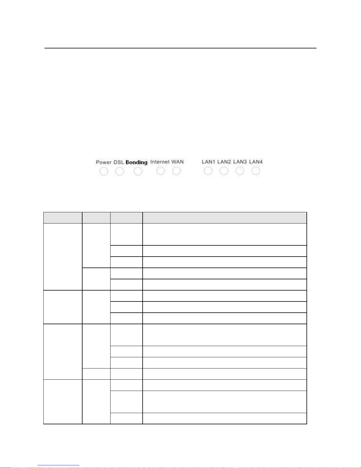
3.1.1 Front Panel
Figure 1 Front panel
The following table describes the indicators on the front panel.
Indicator
Color
Status
Description
Power
Green
On
The device is powered on and the device operates
normally.
Blink
The software is upgrading.
Off
The device is powered off.
Red
On
The device is initiating.
Blink
The software is upgrading.
DSL
Green
On
DSL link has established.
Blink
The DSL line is training.
Off
Device is powered off.
Internet
Green
On
Internet is synchronized successfully in the route
mode.
Blink
Internet data is being transmitted.
Off
Ethernet interface is disconnected.
Red
On
Authentication has failed.
LAN
1/2/3/4
Green
On
The Ethernet interface is connected.
Blink
Data is being transmitted through the Ethernet
interface.
Off
The Ethernet interface is disconnected.
Page 9
User Manual
6
Indicator
Color
Status
Description
Blink
Data is being transmitted.
Off
No signal is detected.
Blink
Data is being transmitted through the wireless
interface.
Off
WLAN is disabled.
Blink
Negotiation is in progress under Wi-Fi Protected
Setup.
Off
Wi-Fi Protected Setup is disabled.
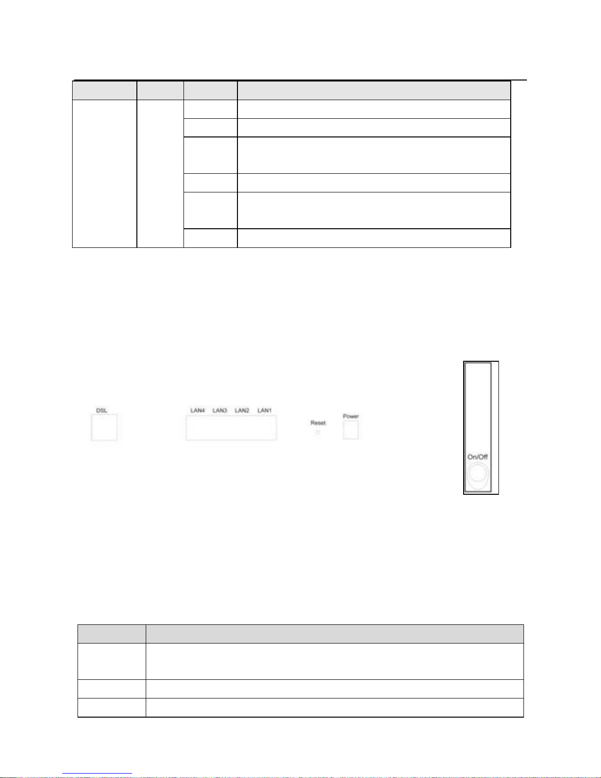
3.1.2 Rear Panel and Side Panel
Figure 2 Rear panel
Figure 3 Side
panel
The following table describes the interfaces and the buttons.
Interface
Description
DSL
RJ-11 port. Connect the router to DSL connector or splitter through
telephone cable.
Page 10

User Manual
7
Interface
Description
LAN 4~1
RJ-45 port, for connecting the router to a PC or another network
device.
WAN
For connecting Ethernet cable to provide Ethernet uplink.
Reset
Press the button for at least 1 second and then release it. System
restores the factory default settings.
Power
Power interface, for connecting the power adapter.
On/Off
Power switch.
Warning:
Do not press the Reset button unless you want to clear the current settings. The
Reset button is in a small circular hole on the rear panel. If you want to restore the
default settings, please press the Reset button gently for 1 second with a fine needle
inserted into the hole and then release the button. The system reboots and returns to
the factory defaults.
3.2 Hardware Installation
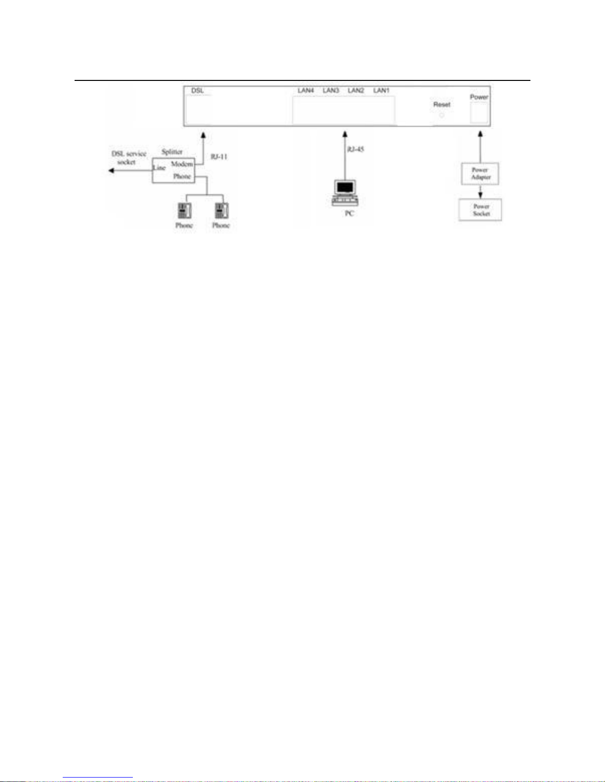
3.2.1 Connecting the Device
Step 1 Connect the DSL port of the router and the Modem port of the splitter
with a telephone cable; connect the phone to the phone port of the
splitter through a cable; and connect the incoming line to the Line port of
the splitter.
The spliiter has three ports:
Line: Connect to a wall phone jack (RJ-11 jack)
Modem: Connect to the Line interface of the router
Phone: Connect to a telephone set
Step 2 Connect the LAN port of the router to the network card of the PC through
an Ethernet cable.
Step 3 Plug the power adapter to the wall outlet and then connect the other end
of it to the Power port of the router.
The followig figure displays the connection of the DSL router, PC, and telephones.
Page 11
User Manual
8
Figure 4 Connecting the DSL router
Note:
If you use the Ethernet uplink, connect the WAN interface that is defined to the
Internet with Ethernet cable.
The xDSL uplink, , and Ethernet uplink can not coexist.
Page 12

User Manual
9
4 PC Network Configuration and Login
4.1 PC Network Configuration
Each network interface on the PC should either be configured with a statically defined
IP address and DNS address, or be instructed to automatically obtain an IP address
using the network DHCP server. DSL router provides a DHCP server on its LAN and
it is recommended to configure your LAN to automatically obtain its IP address and
DNS server IP address.
The configuration principle is identical but should be carried out differently on each
operating system.
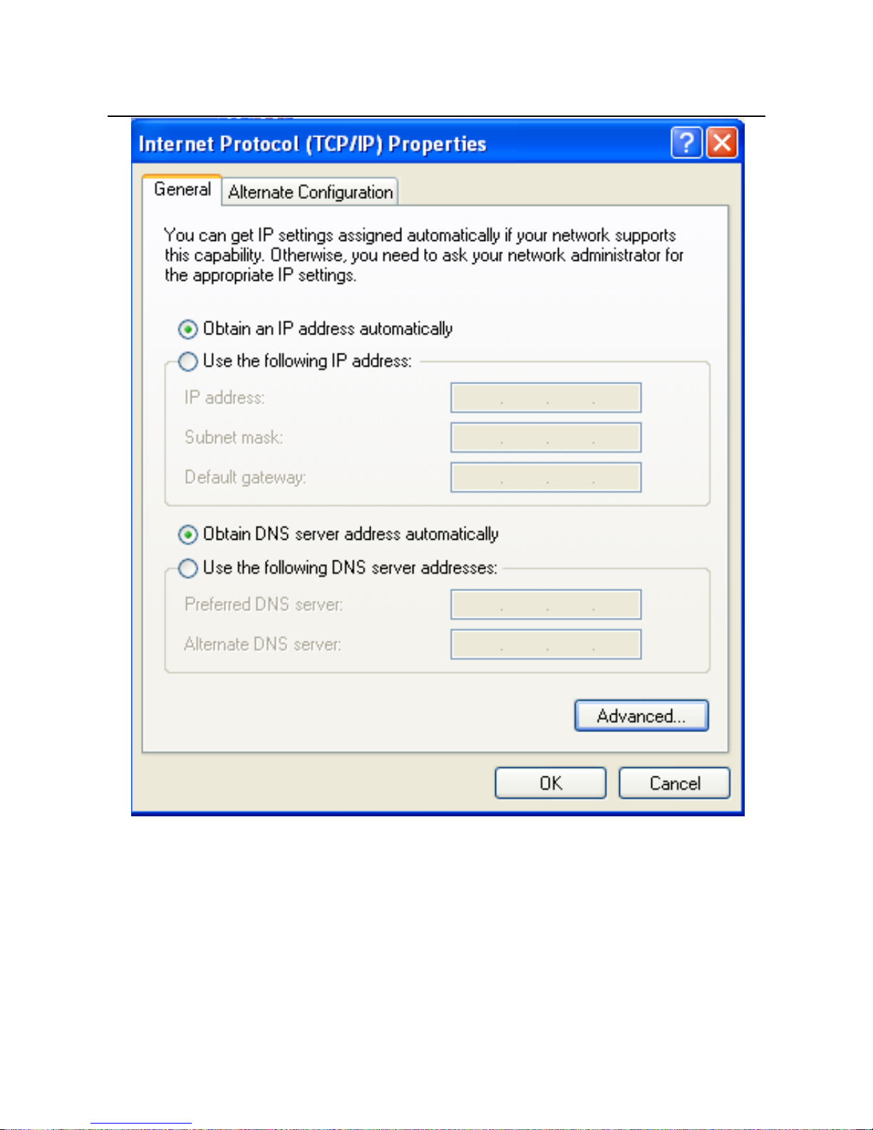
The following displays the TCP/IP Properties dialog box on Windows XP.
Page 13
User Manual
10
Figure 5 IP and DNS configuration
TCP/IP configuration steps for Windows XP are as follows:
Step 1 Choose Start > Control Panel > Network Connections.
Step 2 Right-click the Ethernet connection icon and choose Properties.
Step 3 On the General tab, select the Internet Protocol (TCP/IP) component
and click Properties.
Step 4 The Internet Protocol (TCP/IP) Properties window appears.
Page 14

User Manual
11
Step 5 Select the Obtain an IP address automatically radio button.
Step 6 Select the Obtain DNS server address automatically radio button.
Step 7 If you want to set the IP address and subnet mask manually, you can set
the IP address and subnet mask of the computer to 192.168.1.x and
255.255.255.0 respectively. The range for x is from 2 to 254.
Step 8 Click OK to save the settings.
4.2 Logging In to the DSL Router
To log in to the DSL router, do as follows:
Step 1 Open a Web browser on your computer.
Step 2 Enter http://192.168.1.1 (the default IP address of the DSL router) in the
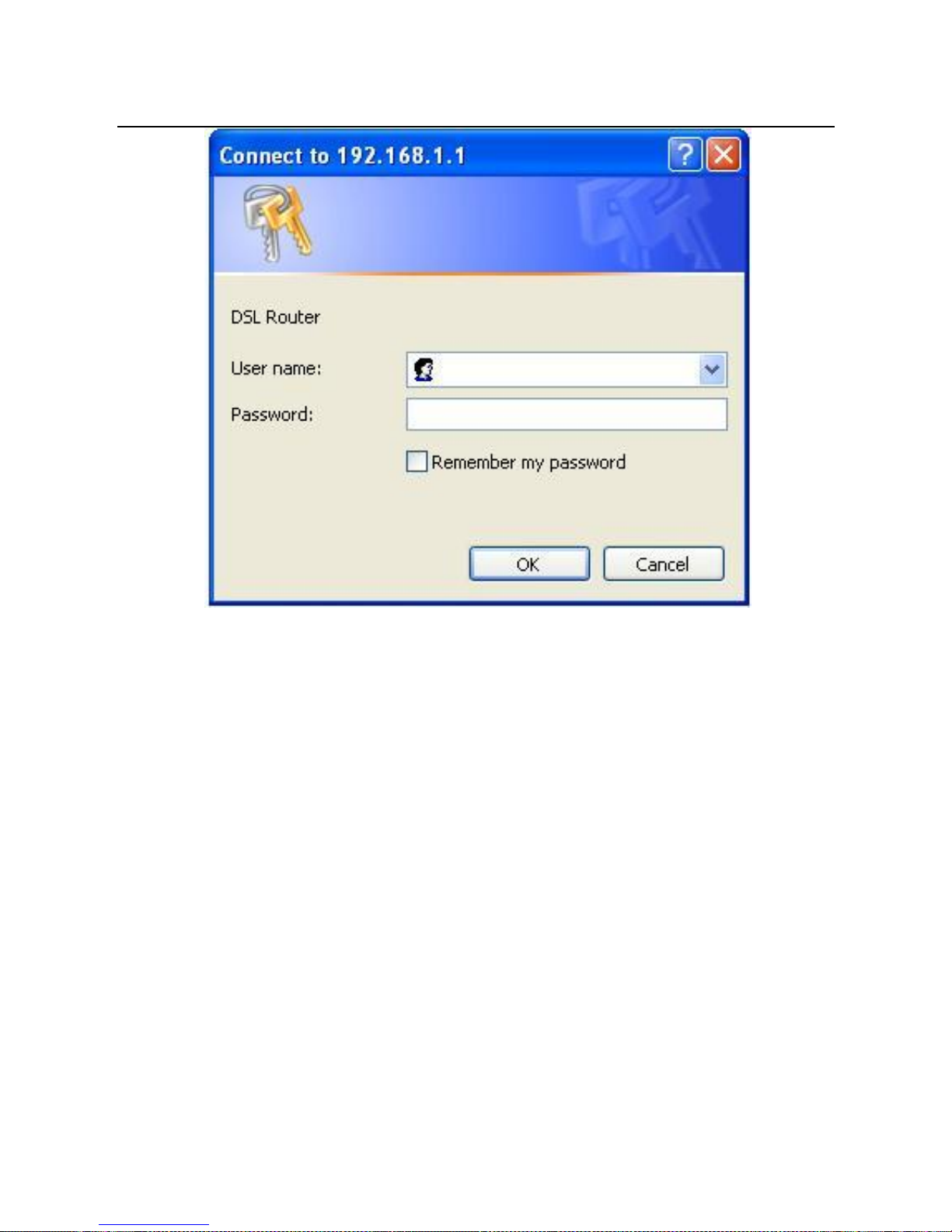
address bar. The login page appears.
Step 3 Enter the user name and the password. The default username and
password of the super user are admin and admin. The username and
password of the common user are user and user. You need not enter
the username and the password again if you select the option
Remember my password. It is recommended to change these default
values after logging in to the DSL router for the first time.
Step 4 Click OK to log in to the Web page. Otherwise, please click Cancel to
exit the login page.
Page 15
User Manual
12
Figure 6 Login page
After logging in to the DSL router as a super user, you can query, configure, and
modify all the settings, and diagnose the system
5 Web-Based Management
This chapter describes how to use Web-based management of the DSL router, which
allows you to configure and control all of DSL router features and system parameters
in a user-friendly GUI.
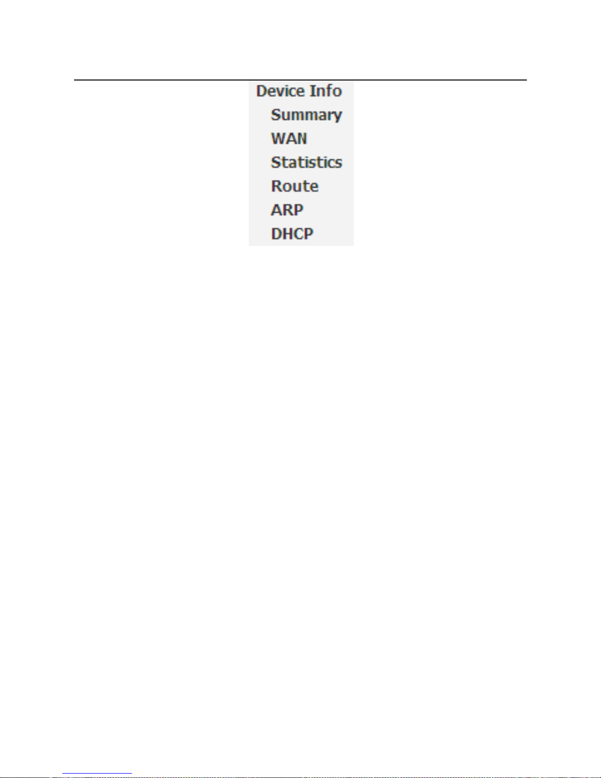
5.1 Device Information
Choose Device Info, and the submenus of Device Info are shown as below:
Page 16
User Manual
13
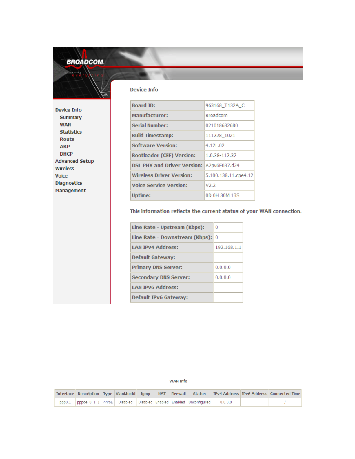
5.1.1 Summary
Choose Device Info > Summary, and the following page appears.
Page 17
User Manual
14
This page displays the device information such as the board ID, software version, and
the information of your WAN connection such as the upstream rate and the LAN
address.
5.1.2 WAN
Choose Device Info > WAN and the following page appears.
Page 18
User Manual
15
This page displays the information of the WAN interface, such as the connection
status, and the IP address.
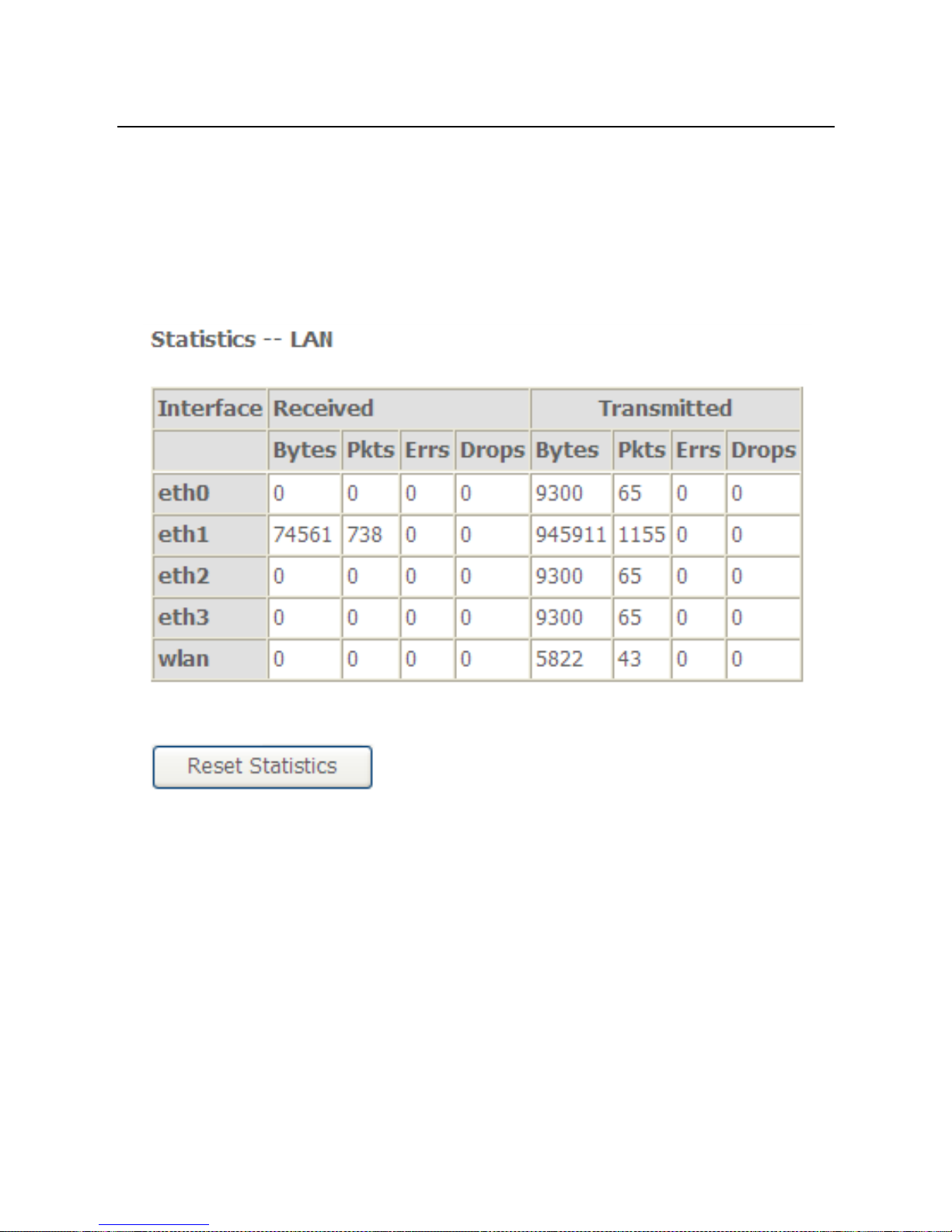
5.1.3 Statistics
5.1.4 LAN
Choose Device Info > Statistics > LAN and the following page appears.
In this page, you can view the statistical information about the recevied and
transmitted data packets of the Ethernet and wireless interfaces.
Click Reset Statistics to restore the values to zero and recount them.
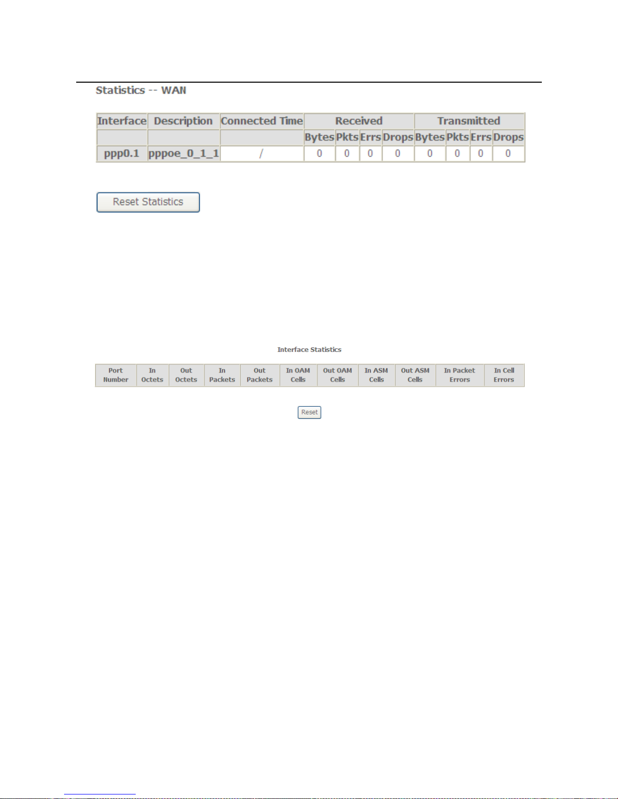
5.1.5 WAN Service
Choose Device Info > Statistics > WAN Service and the following page appears.
Page 19
User Manual
16
In this page, you can view the statistical information about the recevied and
transmitted data packets of the WAN interface.
Click Reset Statistics to restore the values to zero and recount them.
5.1.6 xTM
Choose Device Info > Statistics > xTM and the following page appears.
In this page, you can view the statistical information about the recevied and
transmitted data packets at the xTM interfaces.
Click the Reset button to restore the values to zero and recount them.
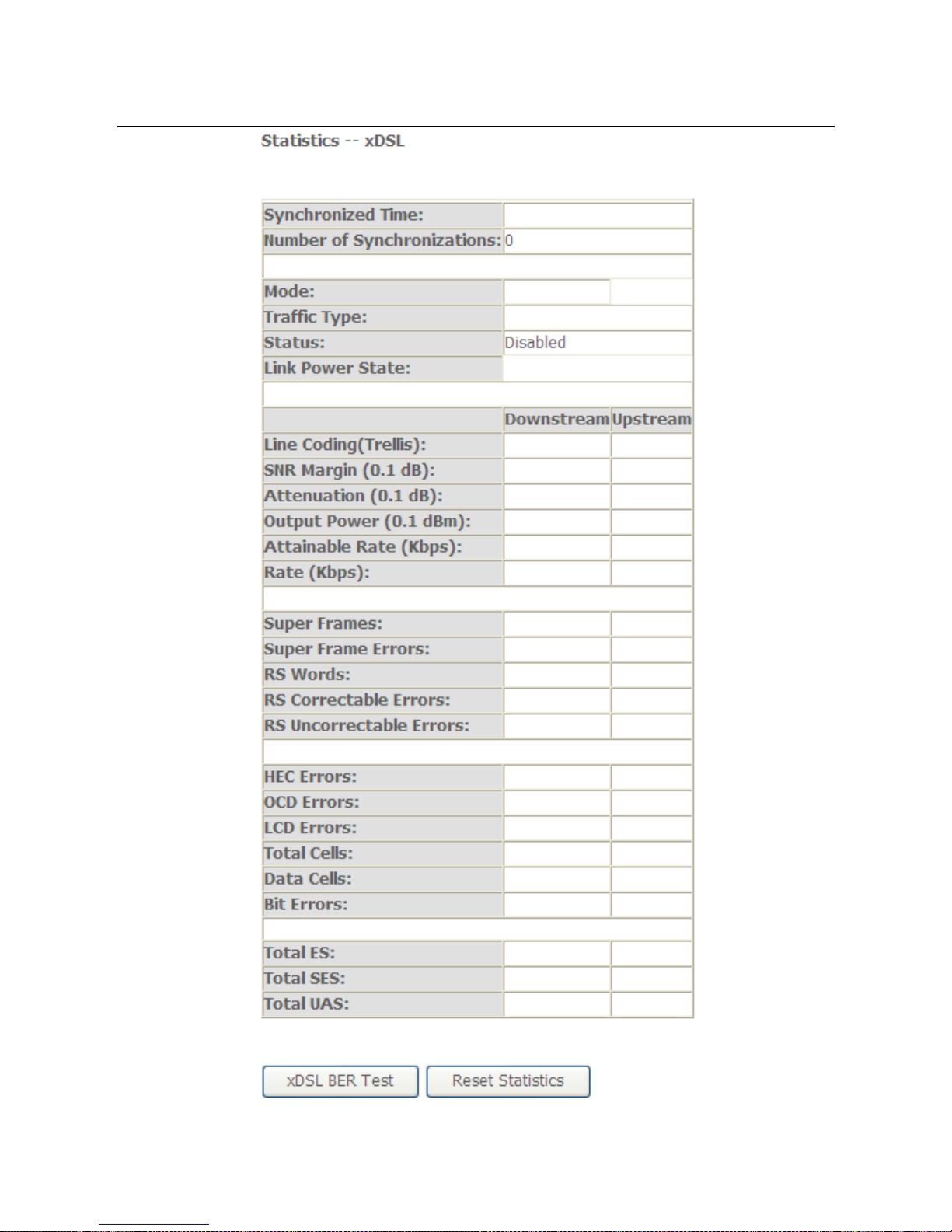
5.1.7 xDSL
Choose Device Info > Statistics > xDSL and the following page appears.
Page 20
User Manual
17
Page 21
User Manual
18
In this page, you can view the statistical information about the recevied and
transmitted data packets of the xDSL interfaces.
Click xDSL BER Test to test the xDSL Bit Error Rate.
Click Reset Statistics to restore the values to zero and recount them.
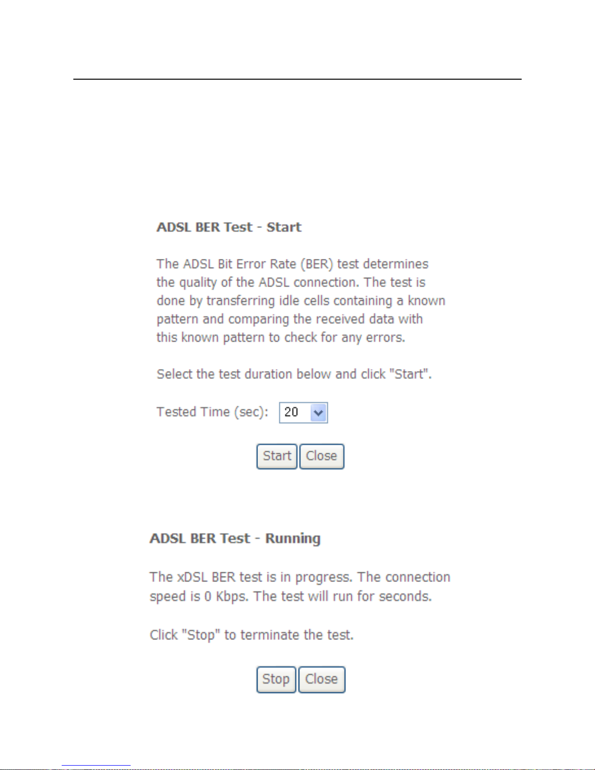
xDSL BER Test
Click xDSL BER Test to perform a bit error rate (BER) test on the DSL line. The test
page is as follows:
The Tested Time (sec) can be 1, 5, 10, 20, 60, 120, 180, 240, 300, or 360. Select a
time in the drop-down list and click Start. The following pages appear.
Page 22
User Manual
19
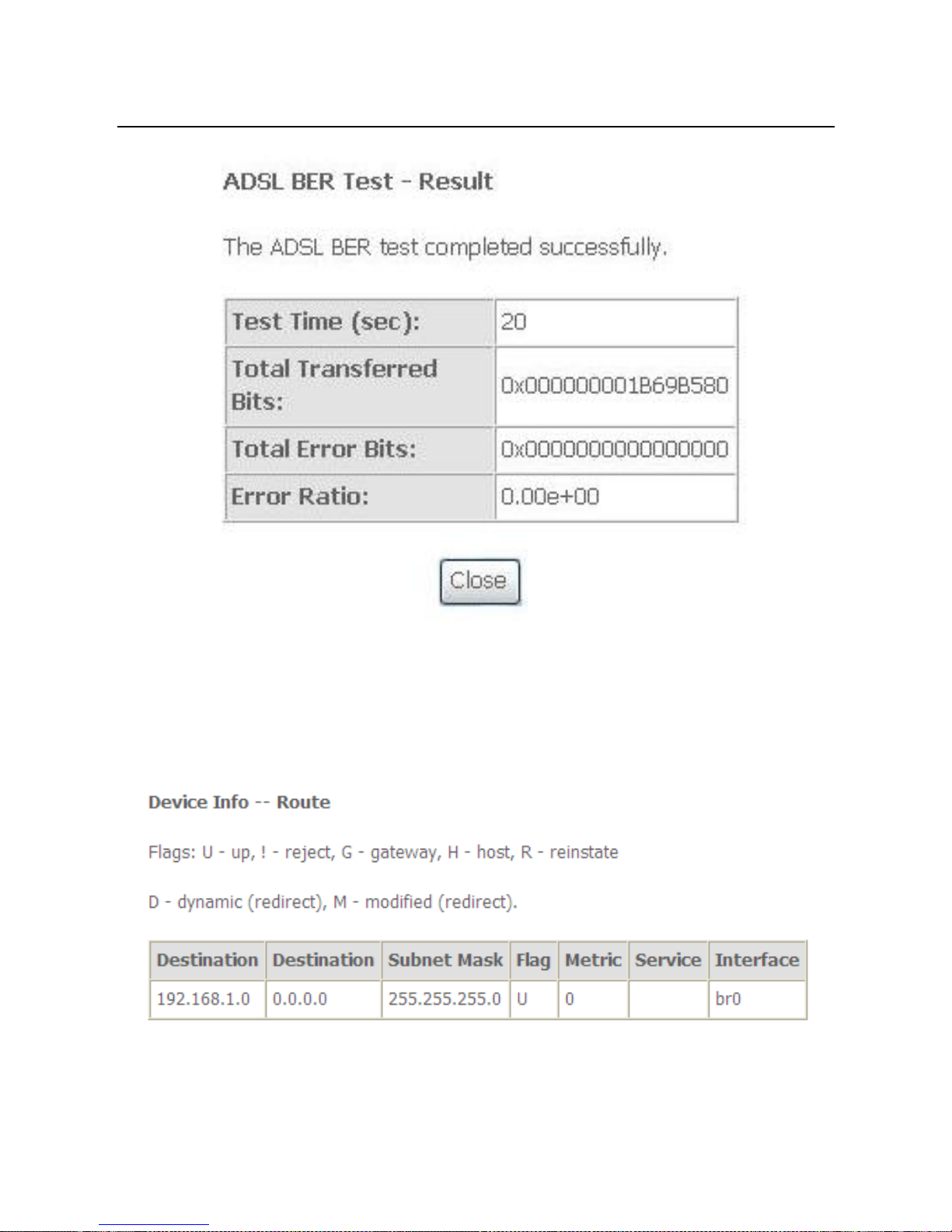
When the ADSL BER test completes, the following page appears.
Note:
If the BER reaches e-5, you cannot access the Internet.
5.1.8 Route
Choose Device Info > Route and the following page appears.
In this page, you can view the route table information.
Page 23
User Manual
20
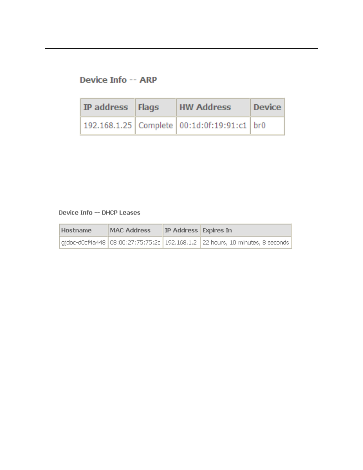
5.1.9 ARP
Choose Device Info > ARP and the following page appears.
In this page, you can view the MAC address and IP address information of the device
connected to the router.
5.1.10 DHCP
Choose Device Info > DHCP and the following page appears.
In this page, you can view the host name, the IP address assigned by the DHCP
server, the MAC address this is corresponding to the IP address, and the DHCP lease
time.
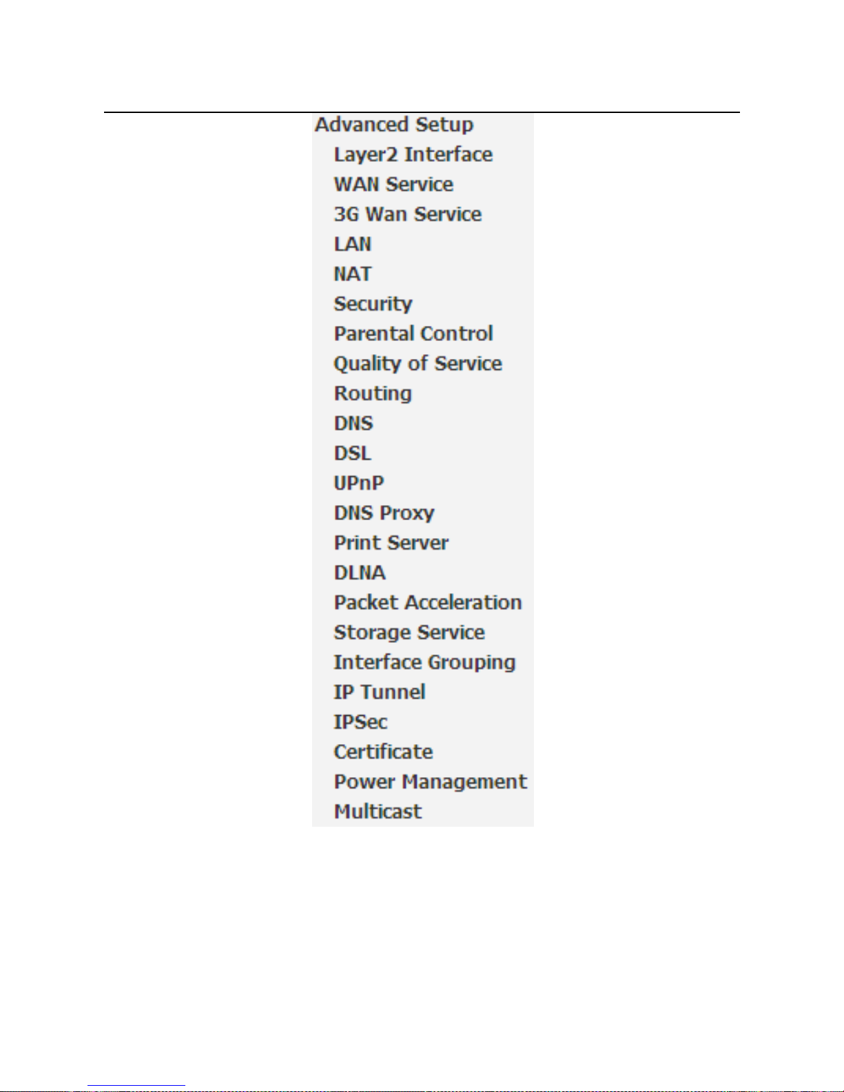
5.2 Advanced Setup
Choose Advanced Setup and the submenus of Advanced Setup are shown as
below:
Page 24
User Manual
21
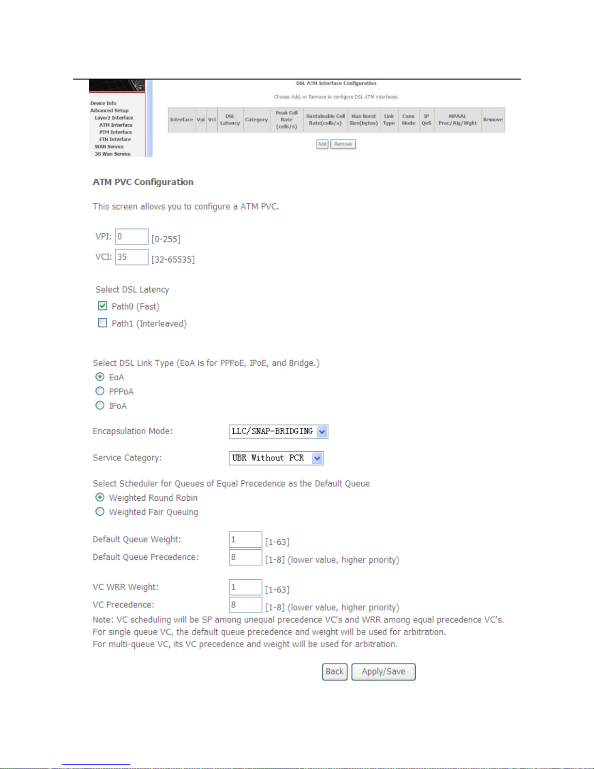
5.2.1 Layer2 Interface
5.2.1.1 ATM Interface
Choose Advanced Setup > Layer2 Interface > ATM Interface . In this page, you
can add or remove to configure DSL ATM Interfaces.
Page 25
User Manual
22
Click Add to add ATM Interface and the following page appears.
Page 26
User Manual
23
In this page, you can enter this PVC (VPI and VCI) value, and select DSL link type
(EoA is for PPPoE, IPoE, and Bridge.), encapsulation mode, service category.
VPI (Virtual Path Identifier): The virtual path between two points in an ATM
network, and its valid value is from 0 to 255.
VCI (Virtual Channel Identifier): The virtual channel between two points in
an ATM network, ranging from 32 to 65535 (1 to 31 are reserved for known
protocols).
DSL Link Type: EoA (it is for PPPoE, IPoE, and Bridge), PPPoA, or IPoA
Encapsulation Mode: LLC/SNAP-BRIDGING, or VC/MUX
Service Category: UBR Without PCR, UBR With PCR, CBR, Non Realtime
VBR, Realtime VBR.
Select Scheduler for Queues of Equal Precedence as the Default
Queue: Weighted Round Robin or Weighted Fair Queuing.
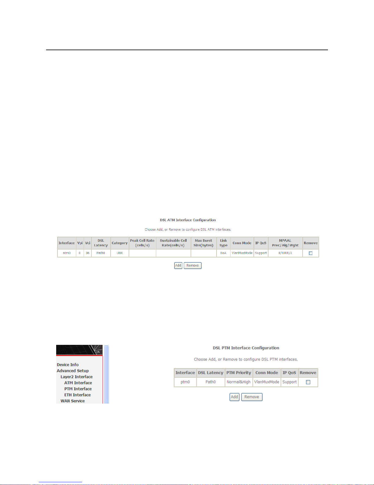
Click Apply/Save to save the configuration, and return the following page:
If you want to remove this Interface, please select the Remove check box and click
Remove.
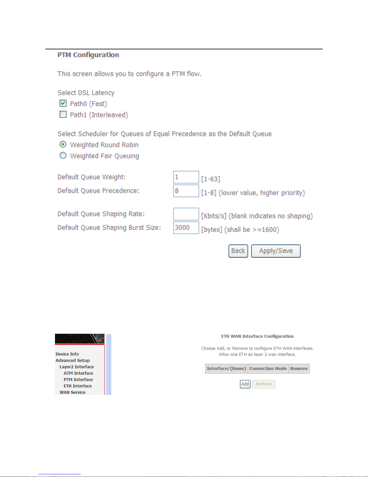
5.2.1.2 PTM Interface
Choose Advanced Setup > Layer2 Interface > PTM Interface, and the following
page appears. In this page, you can add or remove to configure PTM WAN
Interfaces.
Click Add and the following page appears.
Page 27
User Manual
24
In this page, you can select scheduler for queues of equal precedence and enter
the queue value. Click Apply/Save to save configuration.
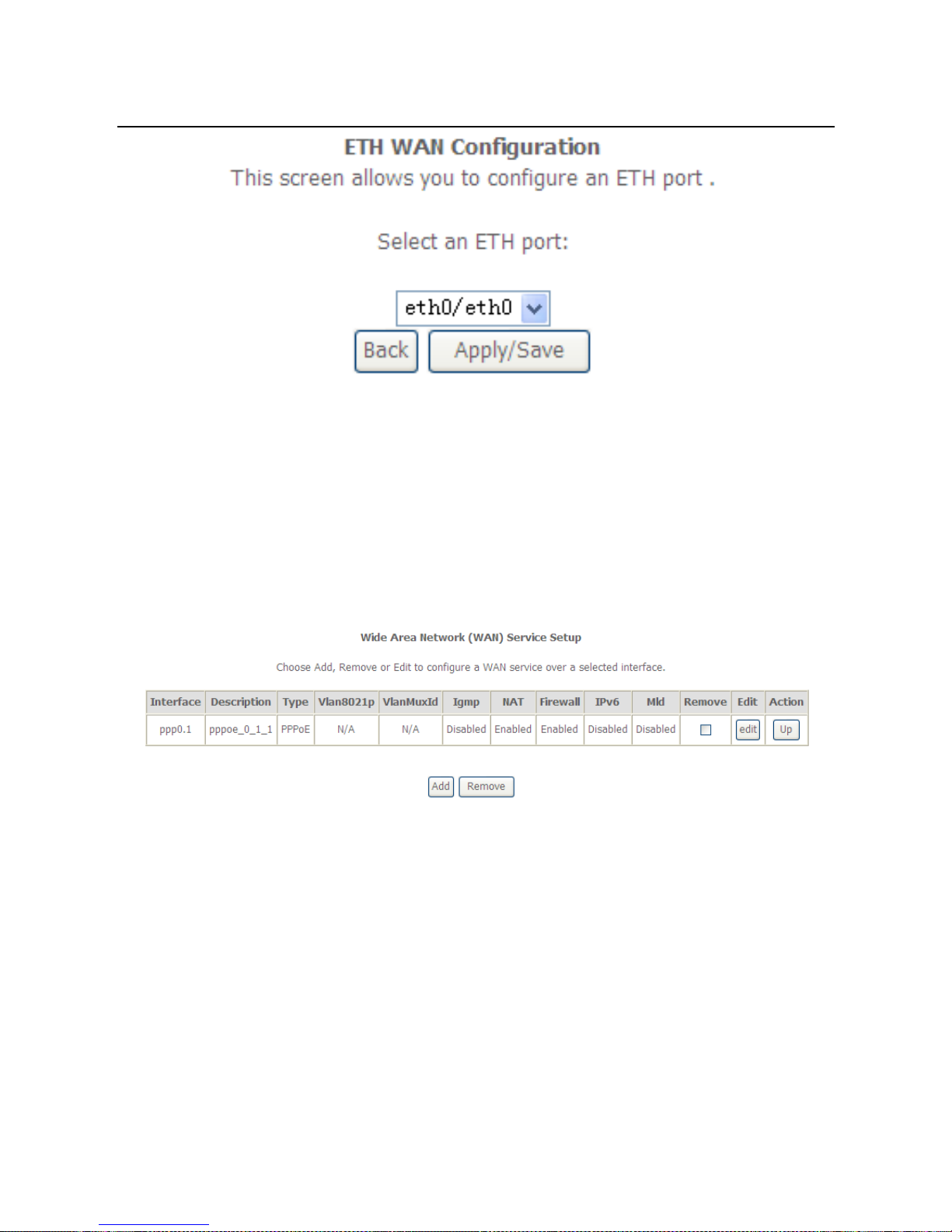
5.2.1.3 ETH Interface
Choose Advanced Setup > Layer2 Interface > ETH Interface, and the following
page appears. In this page, you can add or remove to configure ETH WAN
Interfaces.
Click Add and the following page appears.
Page 28
User Manual
25
In this page, you can select a ETH port. Click Apply/Save to save configuration.
Note:
If ETH Interface is selected, there are two WAN service types (PPPoE and
IPoE).
5.2.2 WAN Service
Choose Advanced Setup > WAN Service, and the following page appears.
In this page, you are allowed to add, remove, or edit a WAN service.
Note:
If PTM Interface is selected, there are three WAN service types: PPP over
Ethernet (PPPoE), IP over Ethernet, Bridging. And the corresponding
configurations of PTM WAN service are same as the configurations of ATM
WAN service.
5.2.2.1 Adding a PPPoE WAN Service
This section describes the steps for adding the PPPoE WAN service.
Page 29
User Manual
26
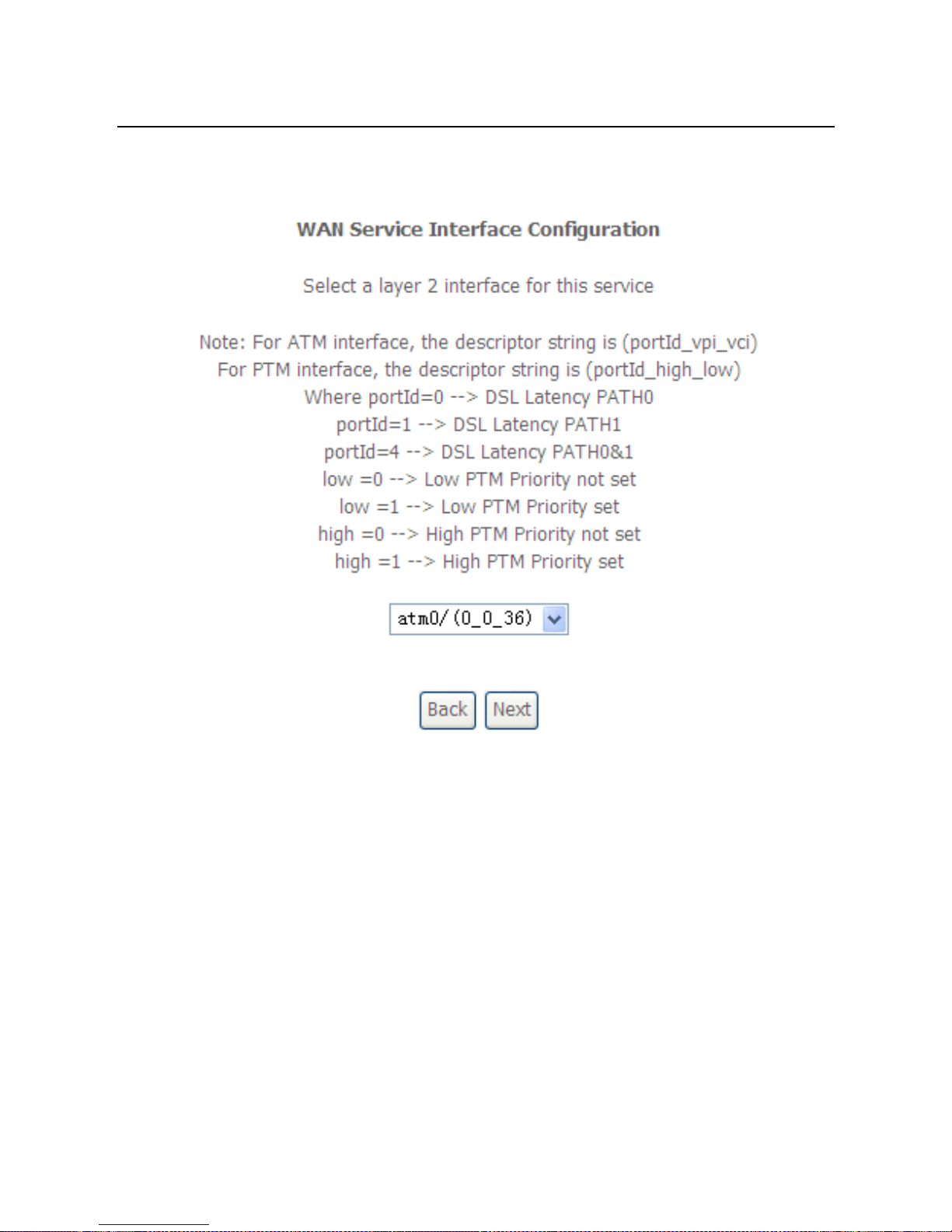
Step1 In the Wide Area Network (WAN) Service Setup page, click the Add
button to display the following page. (At first, you must add a proper ATM
or PTM interface for this WAN service.)
Step2 In this page, you can select a ATM Interface for the WAN service. After
selecting the ATM interface, click Next to display the following page.
Page 30
User Manual
27
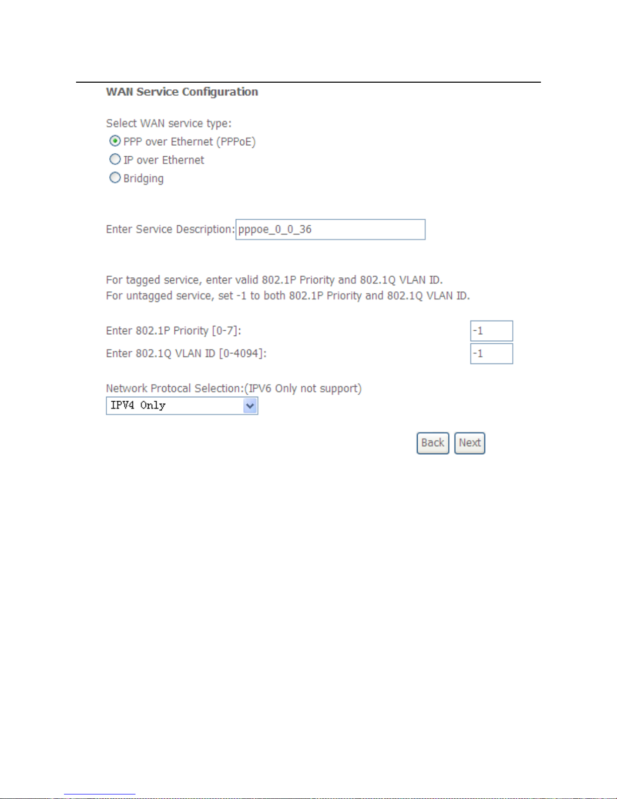
Step3 In this page, select the WAN service type to be PPP over Ethernet
(PPPoE). Click Next to display the following page.
Page 31

User Manual
28
Step4 In this page, you can modify the PPP username, PPP password, PPPoE
service name and authentication method.
PPP Username: The correct user name provided by your ISP.
PPP Password: The correct password provided by your ISP.
PPPoE Service Name: If your ISP provides it to you, please enter it. If not,
do not enter any information.
Authentication Method: The value can be AUTO, PAP, CHAP, or MSCHAP.
Usually, you can select AUTO.
Enable Fullcone NAT:. NAT is one where all requests from the same
internal IP address and port are mapped to the same external IP address
and port. Furthermore, any external host can send a packet to the internal
host, by sending a packet to the mapped external address.
Dial on demand (with idle timeout timer): If this function is enabled, you
need to enter the idle timeout time. Within the preset minutes, if the modem
does not detect the flow of the user continuously, the modem automatically
stops the PPPoE connection. Once it detects the flow (like access to a
webpage), the modem restarts the PPPoE dialup. If this function is disabled,
the modem performs PPPoE dial-up all the time. The PPPoE connnection
Page 32

User Manual
29
does not stop, unless the modem is powered off and DSLAM or uplink
equipment is abnormal.
PPP IP extension: If you want to configure DMZ Host, you should enable it
first.
Use Static IPv4 Address: If this function is disabled, the modem obtains an
IP address assigned by an uplink equipment such as BAS, through PPPoE
dial-up. If this function is enabled, the modem uses this IP address as the
WAN IP address.
Enable PPP Debug Mode:Enable or disable this function.
Bridge PPPoE Frames Between WAN and Local Ports:Enable or disable
this function.
Enable IGMP Multicast Proxy:If you want PPPoE mode to support IPTV,
enable it.
Step5 After setting the parameters, click Next to display the following page.
Step6 In this page, select a preferred WAN interface as the system default
gateway and then click Next to display the following page.
Page 33

User Manual
30
Step7 In this page, you can obtain the DNS server addresses from the selected
WAN interface. Click Next, and the following page appears.
Page 34

User Manual
31
Step8 In this page, it displays the information about the PPPoE settngs. Click
Apply/Save to save and apply the settings.
5.2.2.2 Adding a MER (IPoE) WAN service
This section describes the steps for adding the MER WAN service.
Step1 In the Wide Area Network (WAN) Service Setup page, click the Add
button to display the following page. (At first, you must add a ATM or PTM
interface for this WAN service.)
Step2 Select an ATM Interface, and then click Next to display the following
page.
Page 35

User Manual
32
Step3 In this page, select the WAN service type to be IP over Ethernet, enter
the service description for this service. After finishing setting, click Next to
display the following page.
Page 36

User Manual
33
Step4 In this page, you may modify the WAN IP settings. You may select obtain
an IP address automatically or manually enter the IP address provided by
your ISP. Click Next and the following page appears.
Note:
If selecting Obtain an IP address automatically, DHCP will be enabled for PVC in
MER mode.
If selecting Use the following Static IP address, please enter the WAN IP address,
subnet mask and gateway IP address.
Page 37

User Manual
34
Step5 In this page, you can set the network address translation settings,for
example, enabling NAT, enabling firewall, and enabling IGMP multicast.
After finishing setting, click Next and the following page appears.
Step6 In this page, select a preferred WAN interface as the system default
gateway and then click Next to display the following page.
Page 38

User Manual
35
Step7 In this page, you can obtain the DNS server addresses from the selected
WAN interface. After finishing setting, click Next to display the following
page.
Page 39

User Manual
36
Step8 In this page, it displays the information about the IPoE settngs.Click
Apply/Save to save and apply the settings.
5.2.2.3 Adding a PPPoA WAN service
This section describes the steps for adding the PPPoA WAN service.
Step1 Choose Advanced Setup > Layer2 Interface > ATM Interface to
dsipaly the DSL ATM Interface Configuration page. In this page, you
need to add a PVC for PPPoA mode. Click the Add button in the DSL
ATM Interface Configuration page to display the following page.
Page 40

User Manual
37
Step2 Select the DSL link type to be PPPoA, and select the encapsulation
mode to be VC/MUX (according to the uplink equipment). After finishing
setting, click the Apply/Save button to apply the setings.
Step3 Choose WAN Service and click Add to display the following page.
Page 41

User Manual
38
Step4 Select the proper interface for the WAN service, and then click Next to
display the following page.
Step5 In this page, you may modify the service description. Click Next to
display the following page.
Page 42

User Manual
39
PPP Username: The correct user name provided by your ISP.
PPP Password: The correct password provided by your ISP.
Authentication Method: The value can be AUTO, PAP, CHAP, or MSCHAP.
Usually, you can select AUTO.
Enable Fullcone NAT:. NAT is one where all requests from the same
internal IP address and port are mapped to the same external IP address
and port. Furthermore, any external host can send a packet to the internal
host, by sending a packet to the mapped external address.
Dial on demand (with idle timeout timer): If this function is enabled, you
need to enter the idle timeout time. Within the preset minutes, if the modem
does not detect the flow of the user continuously, the modem automatically
stops the PPPoA connection. Once it detects the flow (like access to a
webpage), the modem restarts the PPPoA dialup. If this function is disabled,
the modem performs PPPoA dial-up all the time. The PPPoA connnection
does not stop, unless the modem is powered off and DSLAM or uplink
equipment is abnormal.
PPP IP extension: If you want to configure DMZ Host, you should enable it
first.
Use Static IPv4 Address: If this function is disabled, the modem obtains an
IP address assigned by an uplink equipment such as BAS, through PPPoA
Page 43

User Manual
40
dial-up. If this function is enabled, the modem uses this IP address as the
WAN IP address.
Enable PPP Debug Mode:Enable or disable this function.
Enable IGMP Multicast Proxy: If you want PPPoE mode to support IPTV,
enable it.
Step6 In this page, you can enter the PPP username and PPP password
provided by your ISP. Select the authentication method according to your
requirement. After finishing setting, click Next to display the following
page.
Step7 In this page, select a preferred WAN interface as the system default
gateway and then click Next to display the following page.
Page 44

User Manual
41
Step8 In this page, you can obtain the DNS server addresses from the selected
WAN interface. After finishing setting, click Next to display the following
page.
Page 45

User Manual
42
Step9 In this page, it displays the information about the PPPoA settngs.Click
Apply/Save to apply the settings. You can modify the settings by clicking
the Back button if necessary.
5.2.2.4 Adding an IPoA WAN service
This section describes the steps for adding the IPoA WAN service.
Step1 Choose Advanced Setup > Layer2 Interface > ATM Interface to
dsipaly the DSL ATM Interface Configuration page. In this page, you
need to add a PVC for IPoA mode. Click the Add button in the DSL ATM
Interface Configuration page to display the following page.
Page 46

User Manual
43
Step2 Select the DSL link type to be IPoA, and select the encapsulation mode
to be LLC/SNAP-ROUTING (according to the uplink equipment). After
finishing setting, click the Apply/Save button to save the settings.
Step3 Choose WAN Service and click Add to display the following page.
Page 47

User Manual
44
Step4 Select the proper interface for the WAN service ,and then click Next to
display the following page.
Step5 In this page, you may modify the service description. Click Next to
display the following page.
Page 48

User Manual
45
Step6 In this page, enter the WAN IP address, the WAN subnet mask, and
primary DNS server provided by your ISP and then click Next to display
the following page.
In this page, Network Address Translation (NAT) allows you to share one Wide
Area Network (WAN) IP address for multiple computers on your Local Area
Network (LAN).
If you do not want to enable NAT, and wish the user of modem to access the
Internet normally, you need to add a route on the uplink equipment. Otherwise, the
access to the Internet fails. Normally, please enable the NAT function.
Page 49

User Manual
46
Step7 After finishing setting, click Next to display the following page.
Step8 In this page, select a preferred WAN interface as the system default
gateway and then click Next to display the following page.
Page 50

User Manual
47
Step9 In this page, you can obtain the DNS server addresses from the selected
WAN interface. After finishing setting, click Next to display the following
page.
Step10 In this page, it displays the information about the IPoA settngs. Click
Apply/Save to save and apply the settings. You can modify the settings
by clicking the Back button if necessary.
5.2.2.5 Adding a Bridge WAN service
This section describes the steps for adding the Bridge WAN service.
Step1 In the Wide Area Network (WAN) Service Setup page, click the Add
button to display the following page. (At first, you must add a proper ATM
or PTM interface for this WAN service.) Click the Add button to display
the following page.
Page 51

User Manual
48
Step2 Select the proper ATM Interface and then click Next to display the
following page.
Page 52

User Manual
49
Step3 In this page, you can select the WAN service type, and modify the service
description for this service. After finishing setting, click Next to display the
following page.
Page 53

User Manual
50
Step4 In this page, it displays the information about the bridge settngs. Click
Apply/Save to save and apply the settings. You can modify the settings
by clicking the Back button if necessary.
5.2.3 LAN Configuration
Choose Advanced Setup > LAN, and the following page appears.
Page 54

User Manual
51
In this page, you can configure an IP address for the DSL router, enable IGMP
snooping, enable or disable the DHCP server, edit the DHCP option, configure the
DHCP advanced setup and set the binding between a MAC address and an IP
address.
Configuring the Private IP Address for the DSL Router
In this page, you can modify the IP address of the device. The preset IP address is
192.168.1.1.
Enabling IGMP Snooping
IGMP snooping enables the router to forward multicast traffic intelligently, instead of
flooding all ports in the VLAN. With IGMP snooping, the router listens to IGMP
membership reports, queries and leave messages to identify the switch ports that are
members of multicast groups. Multicast traffic will only be forwarded to ports identified
as members of the specific multicast group or groups.
Enabling the LAN Side Firewall
Firewall can prevent unexpected traffic on the Internet from your host in the LAN.
In this page, you can enable or disable the LAN side firewall.
Page 55

User Manual
52
Configuring the DHCP Server
If you enable the DHCP sever, the clients will automatically acquire the IP address
from the DHCP server. If the DHCP server is disabled, you need to manually set the
start IP address, end IP address and the lease time for the clients in the LAN.
Editing the DHCP Option60
Click the Edit DHCP Option60 button in the Local Area Network (LAN) Setup page
to display the DHCP Option60 Setup page.
In this page, you can add, edit or delete the DHCP60 options.
Editing the DHCP Option
Click the Edit DHCP Option button in the Local Area Network (LAN) Setup page to
display the DHCP Option Setup page.
In this page, you can add, edit or delete the DHCP options, and these options will be
sent to the DHCP client.
Page 56

User Manual
53
DHCP Advanced Setup
Click the DHCP Advance Setup button in the Local Area Network (LAN) Setup
page to display the following page. In this page, you can enable or disable DHCP for
every LAN interface.
Configuring the DHCP Static IP Lease List
The lease list of static IP address can reserve the static IP addresses for the hosts
with the specific MAC addresses. When a host whose MAC address is in the lease
list of static IP address requests the DHCP server for an IP address, the DHCP server
assigns the reserved IP address to the host.
Click the Add Entries button in the Local Area Network (LAN) Setup page to
display the DHCP Static IP Lease page.
Page 57

User Manual
54
In this page, enter the MAC address of the LAN host and the static IP address that
is reserved for the host, and then click the Apply/Save button to apply the settings.
Configuring the Second IP Address and Subnet Mask for a LAN
Interface
In the Local Area Network (LAN) Setup page, you are allowed to set the second IP
address and the subnet mask for a LAN interface.
After enabling Configure the second IP Address and Subnet Mask for LAN
interface, enter an IP address and a subnet mask for the LAN interface.
After finishing setting, click the Apply/Save button to apply the settings.
5.2.3.1 IPv6 Auto-configuration
Click Advanced Setup > LAN >IPv6 Autoconfig, and the following page appears.
Page 58

User Manual
55
In this page, you can set an IP address for the DSL IPv6 router, enable the
DHCPv6 server, enable RADVD and enable the MLD snooping function.
Enable DHCPv6 Server: WIDE-DHCPv6 is an open-source implementation
of dynamic host configuration protocol for IPv6 (DHCPv6) originally
developed by the KAME project. The implementation mainly complies with
the following standards: RFC3315, RFC3319, RFC3633, RFC3646,
RFC4075, RFC 4272 etc.
Page 59

User Manual
56
Enable RADVD: The router advertisement daemon (RADVD) is run by Linux
or BSD systems acting as IPv6 routers. It sends router advertisement
messages, specified by RFC2461, to a local Ethernet LAN periodically and
when requested by a node sending a router solicitation message. These
messages are required for IPv6 stateless auto-configuration.
Enable MLD Snooping: Multicast Listener Discovery Snooping (MLD
Snooping) is an IPv6 multicast constraining mechanism that runs on Layer 2
devices to manage and control IPv6 multicast groups. By analyzing received
MLD messages, a Layer 2 device running MLD Snooping establishes
mappings between ports and multicast MAC addresses and forwards IPv6
multicast data based on these mappings.
After finishing setting, click the Save/Apply button to apply the settings.
5.2.4 NAT
5.2.4.1 Virtual Servers
Firewall can prevent unexpected traffic on the Internet from your host on the LAN.
The virtual server can create a channel that can pass through the firewall. In that
case, the host on the Internet can communicate with a host on your LAN within
certain port range.
Choose Advanced Setup > NAT > Virtual Servers, and the following page
appears.
In this page, you are allowed to add or remove a virtual server entry.
To add a virtual server, do as follows:
Step 1 Click the Add button to display the following page.
Page 60

User Manual
57
Use interface: Select an interface that you want to configure.
Select a Service: Select a proper service in the drop-down list.
Custom Server: Enter a new service name to establish a user service type.
Server IP Address: Assign an IP address to virtual server.
External Port Start: When selecting a service, the port number will
automatically be displayed. You can modify it if necessary.
External Port End: When selecting a service, the port number will
automatically be displayed. You can modify it if necessary.
Protocol: You may select TCP/UDP, TCP, or UDP in the drop-down list.
Internal Port Start: When selecting a service, the port number will
automatically be displayed. You can modify it if necessary.
Page 61

User Manual
58
Internal Port End: When selecting a service, the port number will
automatically be displayed. You can modify it if necessary.
Step 2 After finishing setting, click Save/Apply to save and apply the settings.
5.2.4.2 Port Triggering
Some applications need some ports to be opened in the firewall for the remote
access. When an application initializes a TCP/UDP to connect to a remote user,
port triggering dynamically opens the open ports of the firewall.
Choose Advanced Settings > NAT > Port Triggering, and the following page
appears.
In this page, you may add or remove an entry of port triggering.
Click the Add button to display the following page.
Page 62

User Manual
59
Use interface: Select an interface that you want to configure.
Select an application: Select a proper application in the drop-down list.
Custom application: Manually define an application.
Trigger port Start: The start port number that LAN uses to trigger the open
port.
Trigger port End: The end port number that LAN uses to trigger the open
port.
Trigger Protocol: Select the application protocol. You may select TCP/UDP,
TCP, or UDP.
Open Port Start: The start port number that is opened to WAN.
Open Port End: The end port number that is opened to WAN.
Open Protocol: Select the proper protocol that is opened to WAN. You may
select TCP/UDP, TCP, or UDP.
After finishing setting, click Save/Apply to apply the settings.
Note:
Page 63

User Manual
60
You can use a single port number, several port numbers separated by commas,
port blocks consisting of two port numbers separated by a dash, or any
combination of these, for example 80, 90-140, 180.
5.2.4.3 DMZ Host
DMZ allows all the ports of a PC on your LAN to be exposed to the Internet. Set the
IP address of the PC to be DMZ host, so that the DMZ host will not be blocked by
firewall.
Choose Advanced Setup > NAT > DMZ host to display the following page.
In this page, enter the IP address of the DMZ host.
After finishing the settings, click the Apply/Save button to apply the settings.
If you want to clear the DMZ function of the host, please delete the IP address of
the host in the field of DMZ Host IP Address, and then click the Apply/Save
button.
5.2.5 Security
Firewall
Choose Security > Firewall and the following page appears.
Click Modify Firewall or Remove Firewall to modify or remove the firewall. And
click Modify Rule or Remove Rule to modify or remove the rule.
Page 64

User Manual
61
Click Add Firewall, and the following page appears.
name: The name of firewall.
interface: You can select LAN or WAN from the drop-down list.
type: You can select IN or OUT from the drop-down list.
defaultaction: You can select Permit or Drop from the drop-down list.
Click Add Rule, and the following page appears.
enabled: Select the check box to enable the firewall rule.
Protocol: You can select UDP, TCP, or ICMP from the drop-down list.
Action: You can select Permit, Drop, or Reject from the drop-down list.
RejectType: You can select the reject type, when you select Reject as the
action.
IcmpType: You can select the type of ICMP packet, when you select ICMP
as the protocol.
origIPAddress: The original IP address.
origMask: The original subnet mask.
origStartPort: The original start port.
origEndPort: The original end port.
Page 65

User Manual
62
destIPAddress: The destination IP address.
destMask: The destination subnet mask.
destStartPort: The destination start port.
destEndPort: The destination end port.
After finishing setting, click Save&Apply to save and activate the rule.
MAC Filtering Setup
In some cases, you may want to manage Layer2 MAC address to block or permit a
computer within the home network. When you enable MAC filter rules, the DSL
router serves as a firewall that works at layer 2.
Note:
MAC filtering is only effective on ATM PVCs configured in bridge mode.
Choose Security > MAC Filtering and the following page appears.
Page 66

User Manual
63
In this page, you can add or remove the MAC filtering rule. You may change the MAC
filtering policy from FORWARDED to BLOCKED by clicking the Change Policy
button.
Click the Add button to display the following page.
Protocol Type: Select the proper protocol type.
Destination MAC Address: Enter the destination MAC address.
Source MAC Address: Enter the source MAC address.
Frame Direction: The direction of transmission frame.
WAN Interface (Configured in bridge mode only): Select the proper WAN
interface in the drop-down list.
After finishing setting, click Apply/Save to save and apply the filtering rule.
5.2.6 Parental Control
Time Restriction
Choose Advanced Setup > Parental Control > Time Restriction, and the
following page appears.
Click the Add button to display the following page.
Page 67

User Manual
64
This page is used to control the time restriction to a special LAN device that
connects to the DSL router. In this page, se the user name and configure the time
settings.
After finishing setting, click the Apply/Save button to save and apply the settings.
Url Filter
Click Advanced Setup > Parental Control > Url Filter, and the following page
appears.
Thisp age is used to prevent the LAN users from accessing some Websites in the
WAN.
In this page, you may select the Exclude URL list type or the Include URL list type.
If you select the Exclude URL list type, it means that the URLs in the list are not
accessible. If you select the select the Include URL list type, you are allowed to
access the the URLs in the list.
Click the Add button to display the following page.
Page 68

User Manual
65
In this page, enter the URL address and its corresponding port number. For
example, enter the URL address http://www.google.com and the port number 80,
and then click the Apply/Save button. See the following figure:
5.2.7 Quality of Service
Enabling QoS
Choose Advance Setup > Quality of Service and the following page appears.
Page 69

User Manual
66
Select Enable QoS to enable QoS and configure the default DSCP mark.
In this page, enable the QoS function and select the default DSCP mark.
After finishing setting, click Apply/Save to save and apply the settings.
Note:
If the Enable Qos checkbox is not selected, all QoS will be disabled for all
interfaces. The default DSCP mark is used to mark all egress packets that do
not match any classification rules.
Queue Configuration
Choose Advanced Setup > Quality of Service > QoS Queue, and the following
page appears.
Page 70

User Manual
67
In this page, you can enable, add or remove a QoS rule.
Note:
The lower integer value for precedence indicates the higher priority.
Click the Add button to display the following page.
Name: Enter the name of QoS queue.
Page 71

User Manual
68
Enable: Enable or disable the QoS queue.
Interface: Select the proper interface for the QoS queue.
After finishing setting, click Apply/Save to save and apply the settings.
QoS Classification
Choose Advanced Setup > Quality of Service > Qos Classification and the
following page appears.
In this page, you can enable, add or remove a QoS classification rule.
Click the Add button to display the following page.
Page 72

User Manual
69
5.2.8 Routing
Default Gateway
Choose Advanced Setup > Routing > Default Gateway, and the following page
appears.
Page 73

User Manual
70
In this page, you can modify the default gateway settings.
Select a proper WAN interface in the drop-down list of Selected WAN Interface as
the system default gateway.
After finishing setting, click Apply/Save to save and apply the settings.
Static Route
Choose Advanced Setup > Routing > Static Route and the following page
appears.
In this page, you can add or remove a static routing rule.
Click the Add button to display the following page.
Page 74

User Manual
71
IP Version: Select the IP version.
Destination IP address/prefix length: Enter the destination IP address.
Interface: select the proper interface for the rule.
Gateway IP Address: The next-hop IP address.
Metric: The metric value of routing.
After finishing setting, click Apply/Save to save and apply the settings.
Policy Routing
Choose Advanced Setup > Routing > Policy Routing and the following page
appears.
In this page, you can add or remove a static policy rule.
Click the Add button to display the following page.
Page 75

User Manual
72
In this page, enter the policy name, source IP and default gateway, and select the
physical LAN port and interface.
After finishing setting, click Apply/Save to save and apply the settings.
RIP
Choose Advanced Setup > Routing > RIP and the following page appears.
In this page, if you want to configure an individual interface, select the desired RIP
version and operation, and then select the Enabled checkbox for the interface.
After finishing setting, click Apply/Save to save and apply the settings.
Page 76

User Manual
73
5.2.9 DNS
DNS Server
Choose Advanced Setup > DNS > DNS Server and the following page appears.
In this page, you can select a DNS server interface from the available interfaces,
manually enter the DNS server addresses, or obtain the DNS address from a WAN
interface.
After finishing setting, click Apply/Save to save and apply the settings.
Dynamic DNS
Choose Advanced Setup > DNS > Dynamic DNS and the following page
appears.
Page 77

User Manual
74
In this page, you are allowed to modify the DDNS settings.
Click the Add button to display the following page.
D-DNS provider: Select a proper DDNS server in the drop-down list.
Hostname: It is the domain name and it can be modified.
Interface: The interface that the packets pass through on the DSL router.
Username: Enter the username for accessing the DDNS management
interface.
Password: Enter the password for accessing the DDNS management
interface.
After finishing setting, click Apply/Save to save and apply the settings.
5.2.10 DSL
Choose Advanced Setup > DSL and the following page appears. In this page, you
can view the DSL settings. Usually, you can keep this factory default setting. The
modem negotiates the modulation mode with the DSLAM. If you select VDSL2
Enabled check box, you can set the VDSL2 parameters on the right area.
Page 78

User Manual
75
In this page, you can set the DSL settings. Usually, you do not need to modify the
factory default settings.
After finishing setting, click Apply/Save to save and apply the settings.
5.2.11 UPnP
Choose Advanced Setup > UPnP and the following page appears.
Page 79

User Manual
76
In this page, you can enable or disable the UPnP function.
After finishing setting, click Apply/Save to save and apply the settings.
5.2.12 DNS Proxy
Choose Advanced Setup > DNS Proxy and the following page appears.
In this page, you can enable or disable the DNS proxy function.
After enabling the DNS proxy function, enter the host name of the broadband
router and the domain name of the LAN network, and then click Apply/Save to
save and apply the settings.
5.2.13 Print Server
Choose Advanced Setup > Printer Server and the following page appears.
Page 80

User Manual
77
In this page, you can enable or disable the printer server.
After finishing setting, click Apply/Save to save and apply the settings.
5.2.14 DLNA
Choose Advanced Setup > DLNA and the following page appears.
In this page, select the Enable on-board digital media server check box, and the
following page appears. In this page, enter the media library path to run digital
media server.
Page 81

User Manual
78
5.2.15 Packet Acceleration
Choose Advanced Setup > Packet Acceleration and the following page appears.
In this page, you can enable packet flow accelerator.
5.2.16 Storage Service
Storage Device Info
Choose Advanced Setup > Storage Service > Storage Device Info and the
following page appears.
This page is used to display the information of the storage device that connects to
the DSL router.
Page 82

User Manual
79
5.2.17 Interface Grouping
Choose Advanced Setup > Interface Grouping and the following page appears.
Interface grouping supports multiple ports to PVC and bridging groups. Each group
will perform as an independent network. To support this feature, you must create
mapping groups with the appropriate LAN and WAN interfaces using the Add
button. The Remove button will remove the grouping and add the ungrouped
interfaces to the default group. Only the default group has IP interface.
Click the Add button to display the following page.
Page 83

User Manual
80
In this page, please follow the on-screen configuration steps to configure the
parameters of the interface grouping.
After finishing setting, click Apply/Save to save and apply the settings.
5.2.18 IP Tunnel
5.2.18.1 IPv6 in IPv4
Choose Advanced Setup > IP Tunnel > IPv6inIPv4 and the following page
appears. The default value is IPv6 in IPv4 information.
Page 84

User Manual
81
Click Add and the following page appears. In this page, you can add a new tunnel.
IPv4 Mask Length: The value is 0 ~ 32.
6rd Prefix with Prefix Length: prefix/length, such as: 2002::/64.
After proper settings, click Apply/Save and the following page appears.
Page 85

User Manual
82
5.2.18.2 IPv4 in IPv6
Choose Advanced Setup > IP Tunnel > IPv4inIPv6 and the following page
appears.
Click Add and the following page appears. In this page, you can add a new tunnel
of IPv4 in IPv6.
5.2.19 IPSec
Choose Advanced Setup > IPSec and the following page appears.
Page 86

User Manual
83
In this page, you can add or remove the IPSec tunnel connections.
Click the Add button to display the following page.
Page 87

User Manual
84
In this page, set the parameters such as the IPSec connection name, tunnel mode,
and remote IPSec gateway address.
If you need to configure the advanced settings of this IPSec tunnel connection,
please click the Show Advanced Settings button to display the other parameters.
After finishing setting, click Apply/Save to save and apply the settings.
Page 88

User Manual
85
5.2.20 Certificate
Local
Choose Advanced Setup > Certificate > local and the following page appears.
In this page, you can acquire the local certificate by creating a certificate request or
importing a certificate. You may also create or remove a certificate.
Creating a New Certificate Request
Click the Create Certificate Request button to display the following page.
In this page, please set the following parameters.
Certificate name: Set the certificate name.
Common Name: The common name is the "fully qualified domain name,"
(or FQDN) used for DNS lookups of your server (for example,
www.mydomain.com). Browsers use this information to identify your Web
site. Some browsers will refuse to establish a secure connection with your
site if the server name does not match the common name in the certificate.
Please do not include the protocol symbol "http://" or any port numbers or
Page 89

User Manual
86
pathnames in the common name. Do not use wildcard characters such as *
or ?, and do not use an IP address.
Organization Name: The name of the organization to which the entity
belongs (such as the name of a company).
State/Province Name: This is the name of the state or province where your
organization's head office is located. Please enter the full name of the state
or province.
Country/Region Name: This is the two-letter ISO abbreviation for your
country (for example, GB for the United Kingdom).
After finishing setting, click the Apply button to apply the settings.
The certificate request needs to be submitted to a certificate authority, which will
sign the request. Then the signed certificate needs to be loaded to the DSL router.
Click Load Signed Certificate in this page, and the following page appears.
Page 90

User Manual
87
In this page, paste the signed certificate, and then click the Apply button. A new
certificate is created.
Importing an Existing Local Certificate
To import an existing certificate, click the Import Certificate button to display the
following page.
Page 91

User Manual
88
In this page, paste the certificate and the private key. Finally, click the Apply button
to import the certificate.
Trusted CA
Choose Advanced Setup > Certificate > Trusted CA and the following page
appears.
Page 92

User Manual
89
In this page, you may import or remove a CA certificate.
Click the Import Certificate button to display the following page.
In this page, enter the certificate name and paste the certificate content. Finally,
click the Apply button to import the certificate.
5.2.21 Power Management
Choose Advanced Setup > Power Management and the following page appears.
This page allows control of Hardware modules to evaluate power consumption.
Use the control buttons to select the desired option.
Page 93

User Manual
90
After proper configurations, click Apply to take the configurations effect.
5.2.22 Multicast
Choose Advanced Setup > Multicast and the following page appears.
Page 94

User Manual
91
In this page, you can configure the multicast parameters.
After finishing setting, click Apply/Save to save and apply the settings.
5.3 Management
Choose Management and the submenus of Management are shown as below:
Page 95

User Manual
92
5.3.1 Settings
Backup
Choose Management > Settings > Backup to display the following page.
In this page, click the Backup Settings button to save your router’s settings to your
local PC.
Update
Choose Management > Settings > Update, and the following page appears.
In this page, click the Browse… button to select the correct new settings file, and
then click the Update Settings button to update the router’s settings.
Page 96

User Manual
93
Restore Default
Choose Management > Settings > Restore Default to display the following page.
In this page, click the Restore default settings button, and then system returns to
the default settings.
5.3.2 System Log
Choose Management > System Log to display the following page.
In this page, you are allowed to configure the system log and view the security log.
Configuring the System Log
Click the Configure System Log button to display the following page.
In this page, you can set 3 types of system log modes, including Local, Remote, and
Both.
Page 97

User Manual
94
Local: When selecting Local, the events are recorded in the local memory.
Remote: When selecting Remote, the events are sent to the specified IP
address and UDP port of the remote system log server.
Both: When selecting Both, the events are recorded in the local memory or
sent to the specified IP address and UDP port of the remote system log
server.
After finishing setting, click the Apply/Save button to save and apply the settings.
Note:
If you want to log all the events, you need to select the Debugging log level.
View System Log
Click the View System Log button to display the following page.
In this page, you can view the system log.
Click the Refresh button to refresh the system log. Click the Close button to exit.
5.3.3 SNMP Agent
Choose Management > SNMP Agent, and the following page appears.
Page 98

User Manual
95
Simple Network Management Protocol (SNMP) allows a management application to
retrieve statistics and status from the SNMP agent in this device.
In this page, you may enable or disable the SNMP agent and set the parameters such
as the read community, system name and trap manager IP.
After finishing setting, click the Save/Apply button to save and apply the settings.
5.3.4 TR-69 Client
Choose Management > TR-069Client to display the following page.
Page 99

User Manual
96
WAN Management Protocol (TR-069) allows an Auto-Configuration Server (ACS) to
perform auto-configuration, provision, collection, and diagnostics to this device.
In this page, you may configure the parameters such as the ACS URL, ACS
password, and connection request user name.
After finishing setting, click the Apply/Save button to save and apply the settings.
5.3.5 Internet Time
Choose Management > Internet Time to display the following page.
Page 100

User Manual
97
In this page, you may configure the router to synchronize its time with the Internet
time servers.
After enabling Automatically synchronize with Internet time servers, the following
page appears.
 Loading...