

Page 1

OV 303R 2 M Brid ge Mod em
(TR069)
User Man ual
Ver: 1.10
Page 2

Contents
Chapter 1 Introduction.....................................................1
1.1 Features.........................................................................1
1.2 Encapsulation support...................................................1
1.3 System requirements.....................................................1
1.4 LED status description..................................................2
1.5 Rear panel layout..........................................................2
Chapter 2 Hardware Installation......................................4
Chapter 3 Parameters Setting...........................................5
3.1 Network adaptor TCP/IP configuration........................5
3.2 RFC 1483 Bridge dial-up..............................................9
Chapter 4 Questions & Answers....................................14
Page 3

Us e r man ual
1
Chapter 1 Introduction
The device is the ADSL CPE (Customer Premise Equipment) with ATU-R
module, which complies with various ADSL standards, and excellent
interoperation.
1.1 Features
z Full rate ADSL modem
z Provide up to 24Mbps downstream and up to 1.2Mbps
upstream.
z Support TR069
z Complies with full rate ADSL standards:
ANSI T1.413 ISSUE 2
ITU -T G.992.1 (G.dmt)
ITU-T G.992.2 (G.Lite)
ITU G.992.3 (ADSL2)
ITU G.992.5 (ADSL2+)
1.2 Encapsulation support
RFC 1483 bridge
1.3 System requirements
Recommended system requirements are:
z Pentium 233MHz or above
z Memor y: 6 4MB or ab ove
z 10M Base-T Ethernet or above
z Win9X, W in2 000, WinXP, WinME, WinNT
Page 4
Us e r man ual
1.4 LED status description
Indicator Status Description
Off
No power
Power
On
Power on
Blink
Ethernet data transferring
LAN
On
Connected to the network card or
HUB
Blink
DSL line is training
ADSL
ON
DSL line is connected
DATA Blink
DSL data transferring
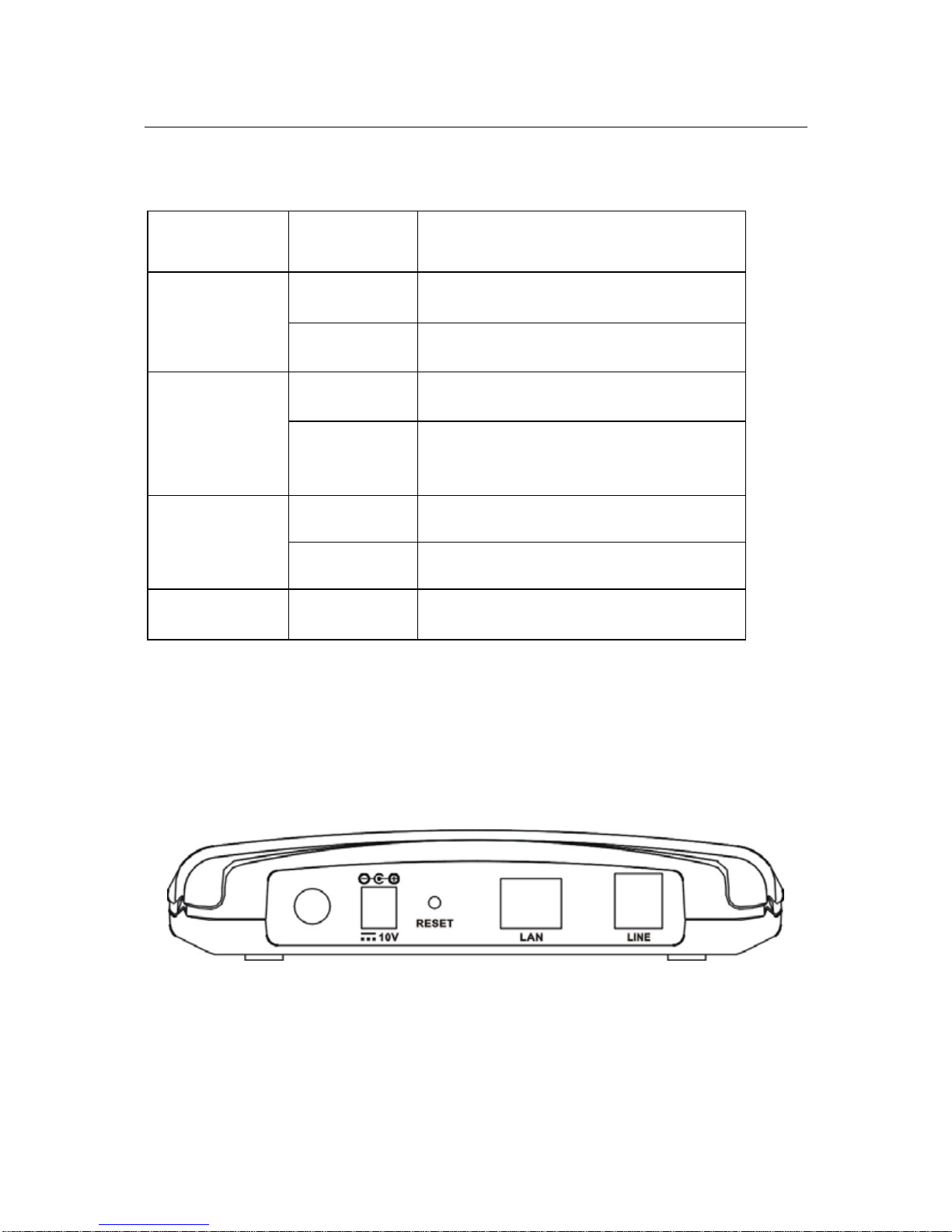
1.5 Rear panel layout
2
Page 5

Us e r man ual
3
Interface Description
Switch Power on/off switch
Power Plug in for power adaptor
Reset
Modem Reset button, switch off then press
“reset” button and switch on 4s to reset the
hardware. The modem will auto restart. This
action will recover the modem’s default
configuration.
LAN
LAN interface for connecting to computer or
Switch
Line
ADSL connector for connecting to ADSL
telephone line
Page 6

Us e r man ual
Chapter 2 Hardware Installation
Please connect your device to computer as following descripti on:
z If connecting to the splitter, connect the “Line” splitter to wall jack
using one telephone cable
z Use the other telephone cable to connect “MODEM” port of the
splitter and “LINE” port of the modem. The “phone” port of the
splitter can be use to connect the telephone and the splitter by a
telephone cable.
z Use E th ern et ca b le t o conn e ct “LAN” por t of the m ode m an d “LAN”
por t of your com puter.
If do not need to connect to the splitter,
z Connect the modem to wall jack using one telephone cable
z Use E th ern et ca b le t o conn e ct “LAN” por t of the m ode m an d “LAN”
port of your compute
4
Page 7

Us e r man ual
5
Chapter 3 Parameters Setting
This section will be the guideline for connecting the device to the Internet.
There are two ways to visit Int ernet via the device.
3.1 Network adaptor TCP/IP configuration
Note: Pleas e col lect the neces sar y information incl uding I P add ress
/G at e way/D NS se rver from your AD S L s e rvice p rovid er be for e you
start to config ure TCP/IP prop erti es
You can connect the device to Internet without dial-up (It depends on
service your ISP provided).
3.1.1 Dynamical IP configuration
Fallow below steps and your can let your computer get an IP address from a
DHCP server aut omatically.
Open the “Internet Protocol (TCP/IP) Properties” window, select Obtain
an IP address automatically and Obtain DNS service automatically, click
OK to confirm and save the changes of “Internet protocol (TCP/IP)
properties”.
Page 8

Us e r man ual
3.1.2 Static IP configuration
Take Windows 2000 as an example, the setting procedures in other
operat ing systems are similar with the following descripti on. In static
IP address mode, if you have the information of the IP and DNS
address, please follow below steps to configure the TCP/IP
properties
Step 1:
Select Start-Settings-Network and Dial-up connection, Select the icon of
“Local Ar ea Connec tion” and open it.
6
Page 9

Us e r man ual
Step 2:
Select Local Area Connections and open “Local Area connections
Properties” window. Then double click Internet Protocol (TCP/IP).
7
Page 10

Us e r man ual
Step 3:
The “Internet Protocol TCP/IP Properties” window will pop up.
Select Use the following IP address and type the IP address, Subnet mask
and default gat ew ay.
Then select Use the following DNS service address and type the DNS server
address.
Step 4:
Click OK to confirm and save the changes of “Internet protocol (TCP/IP)
properties”.
Then you can enjoy the high-speed Internet visiting with your Internet
explorer.
8
Page 11

Us e r man ual
9
3.2 RFC 1483 Bridge dial-up
For Windows 95/98/Me, you need to install third party dial up software that
can be obtained from ISP. You can dial up with RFC1483 Bridge protocol
support as fo llo w:
Step 1:
Check your hardware connection followed Chapter 2 Then power on
the modem and wait for the ADSL connection established by the LINK
LED is solid on
Step 2:
Install third-party dial-up program such as Enternet300/500. Please
contact your ADSL service provider if you don’t have the PPPoE dialer.
Step 3:
Dial up by the PPPoE dialer with your correct username/password.
For Windows 2000/XP, use built in PPPoE component as follow:
1) Select Start-All Programs -A ccessories-C ommunica t ions-
Netw ork con nections.
Page 12

Us e r man ual
2) Select Connect to the In terne t, and then click Next.
3) In “New Connection Wizard” window, please select Set up my
connection manually, and then click Next.
10
Page 13

Us e r man ual
4) Select Connect using a broadband connection that requires a user
name and password, th en click Next.
5) Enter the name of y our ISP, and then click Next.
11
Page 14

Us e r man ual
6) Enter user n ame and pas swor d, an d then cli ck Next.
7) The following window will be shown. Select Add a shortcut to this
12
Page 15

Us e r man ual
connection to my desktop, then click Finish. A shortcut of dial-up
connection will be created on the desktop.
8) Double click the icon of dial-up connection, and a message window
will pop up. You can click Connect, just wait for a few seconds; you are
ready to visit the Inter net.
13
Page 16

Us e r man ual
14
Chapter 4 Questions & Answers
1. Qu esti on: Why are all l ed ind ica tors off ?
Answer:
Check the connection between the power adaptor and the power
socket, and then check the power swi t ch is on or not.
2. Ques tion: Why does n ’t the LAN led lig h t?
Answer:
Check the connection between the ADSL modem and your computer,
Hub or Switch.
Check your PC, Hub or Swit ch running status and make sure that they
are working normally.
3. Question: Why doesn’t the ADSL led light?
Answer:
Check the connection between the ADSL “line” port and the wall jack.
4. Question: Why doesn’t it connect to Internet?
Answer:
Check ADSL Mode m se tting is right or not.
Pres s “reset” button, reset hard ware into default status .
 Loading...