

Page 1

Live-FSH8R Live-FSH8R Live-FSH8R Live-FSH8R
Live-FSH8R Live-FSH8R Live-FSH8R Live-FSH8R
Live-FSH8R Live-FSH8R Live-FSH8R Live-FSH8R
Live-FSH8R Live-FSH8R Live-FSH8R Live-FSH8R
Live-FSH8R Live-FSH8R Live-FSH8R Live-FSH8R
Live-FSH8R Live-FSH8R Live-FSH8R Live-FSH8R
Live-FSH8R Live-FSH8R Live-FSH8R Live-FSH8R
LiLi
vv
8 - port NWay 10/100 BASE-TX
Fast Ethernet Switch
e-FSH8Re-FSH8R
Li
v
e-FSH8R
LiLi
vv
e-FSH8Re-FSH8R
Installation Guide
Live-FSH8RLive-FSH8R
Rev :
Live-FSH8R V.1.0
Live-FSH8RLive-FSH8R
Published : July 2000
Page 2

Trademarks
All rights reserved.
All compa ny brands and product na me s are trademarks or
registered trade marks of the ir re spective companies.
Disclaimer
Contents in this ma nual are subject to changes without prior
notice.
FCC Warning
This equipment has been tested and found to comply with the
requirements for a Cla ss A digital device, pursuant to Part 15 of
the FCC Rules. These require ments are designed with reasona ble
protection against harmful interference when operating in a
commercial environment. This equi pment ca n generate a nd radi ate
electromagnetic energy a nd, if not installed a nd used in accorda nce
with the instructions on this guide, may cause significant
interference with radio communication. Operation of this
equipment in a residential area is likely to cause interference to
household appli ances, in which case the user will be required to
amend at his or her own expense.
CE Mark Warning
This is a Class A product. In a domestic environment, this product
may cause radio interference, in which case the user may be
required to take adequate preventive measures.
Page 3

About This Guide
✍
Purpose
This manual aims at helping users to know the key features of
Live-FSH8R Fast Ethernet Switch a nd to install it in a 10BASE-
T/100BASE-TX Fast Ethernet Local Area Network (LAN).
Page 4

ii About This Guide
Table of Contents
Chapter 1 Product Overview
Introduction . . . . . . . . . . . . . . . . . . . . . . . . . . . . . . . . . . . . . . 1-1
Perfect Compa nion f or LAN users in SOHO Scenario. . . .1-2
What is 10/100 Mbps Dual-Speed Switching? . . . . . . . . . 1-3
Product Features . . . . . . . . . . . . . . . . . . . . . . . . . . . . . . . . . .. 1-4
Chapter 2 Preparation before Installation
Unpack the Package . . . . . . . . . . . . . . . . . . . . . . . . . . . . . . . . 2-1
The Front Pa nel. . . . . . . . . . . . . . . . . . . . . . . . . . . . . . . . . . . . 2-2
The Rear Pa nel . . . . . . . . . . . . . . . . . . . . . . . . . . . . . . . . . . . . 2-3
Heat Dissi pation . . . . . . . . . . . . . . . . . . . . . . . . . . . . . . . . . . . 2-4
Chapter 3 Installation of the Switch
Quick Installation . . . . . . . . . . . . . . . . . . . . . . . . . . . . . . . . . . 3-1
Desktop Installation . . . . . . . . . . . . . . . . . . . . . . . . . . . . . . . . 3-2
Installation on W all . . . . . . . . . . . . . . . . . . . . . . . . . . . . . . . . 3-3
Installation Site Preparation . . . . . . . . . . . . . . . . . . . . . . . . . 3-4
Cabling Requirements . . . . . . . . . . . . . . . . . . . . . . . . . . . . . . 3-5
Connecting to Power. . . . . . . . . . . . . . . . . . . . . . . . . . . . . . . .3-8
Chapter 4 Expanding Y our Network
Connectivity Rules. . . . . . . . . . . . . . . . . . . . . . . . . . . . . . . . . .4-1
Switch-to-Hub Connection. . . . . . . . . . . . . . . . . . . . . . . . . . .4-2
Switch-to-Switch (other device) Connection. . . . . . . . . . . 4-3
Connecting with a Switch (or Hub) without Uplink Port . .4-3
Transmission Modes. . . . . . . . . . . . . . . . . . . . . . . . . . . . . . . .4-7
Applications.... . . . . . . . . . . . . . . . . . . . . . . . . . . . . . . . . . . . . 4-7
Chapter 5 LED Indicators
LED Status during Power-on Self-test . . . . . . . . . . . . . . . . . 5-2
Power LED . . . . . . . . . . . . . . . . . . . . . . . . . . . . . . . . . . . . . . . . 5-2
DIAG LED . . . . . . . . . . . . . . . . . . . . . . . . . . . . . . . . . . . . . . . . 5-3
ENLOOP LED . . . . . . . . . . . . . . . . . . . . . . . . . . . . . . . . . . . . . 5-3
Port Status LEDs . . . . . . . . . . . . . . . . . . . . . . . . . . . . . . . . . . 5-3
Station-port LEDs (Port 1 to Port 8) . . . . . . . . . . . . . . . . . . . 5-3
Appendix A Product Specifications
Appendix B T roubleshooting
Page 5

Introduction
1
Introduction
8-Port 10/100 Mbps Auto-sensing Dual Speed Switch
Live-FSH8R Fast Ethernet Switch is an 8-port auto-sensing a nd auto-
negotiating Dual-speed Fast Ethernet Switch with one Uplink port. It
is designed with a view to provide SOHO users with maximum benefit
to work in a SOHO LAN environment. All of its 8 RJ-45 station ports
support Dual Speed with auto-sensing and auto-negotiating functions.
The Uplink port is provided for connection with another switch or
hub. All its 8 station ports can automatically a da pt to data rate s ranging
from 10 Mbps (Ethernet half-duplex mode) to 200 Mbps (Fast Ethernet
full-duplex mode). With auto-sensing function, Live-FSH8R
automatically detects the speed of the devices you plugged into, and
routes the incoming data to its destination. Its auto-negotiating function
also allows existing devices with different speeds to communicate
easily within the same network. With these advantages, you have no
further costs for unnecessary or expensive upgrade.
Store-and-Forward Ar chitectur e against Pa cket Loss
It is recognized that when network is under heavy traffic, the shared
memory buffer in the switching devices might yield incorrect detection
due to an overfed memory buffer. This drawback in transmission
sometimes can ha ppen either when data be ing transmitted in IEEE802.
3x Full Duplex or Back Pressure Flow Control mode. To amend this
problem, Live-FSH8R Fast Ethernet Switch utilizes a fixed memory
buffer allocation with Store-and-forward transmission to ensure an
effective buffer allocation for each port. Store-and-forward
transmission controls data flow from transmitting to receiving nodes
with the receiving buffer threshold adjusted to optimal value,
guaranteeing against all possible packet losses.
Page 6

1-2 Introduction
Active Flow Control
Live-FSH8R Fast Ethernet Switch implements in full duplex mode a
Flow Control, which is compliant to IEEE 802.3x standard. While in
half duplex mode, it employs a n optional Ba ck Pre ssure Flow Control
to stall the incoming data when port buffers being saturated. With
this flow control mechanism, it can be ensured that frames dropped
during tra nsmission are reduced to a minimum.
Non-blocking Wire Speed
Live-FSH8R’s non-blocking cross-bar matrix architecture provides
high-end performance for departmental and workgroup environments
at a fraction of the cost of similar devices. Typically, this type of
architecture is found only in high-end switches designed to handle
huge corporate networks. With bandwidth needs and network efficiency
concerns, Live-FSH8R’s switching fa bric de sign is the perfect answer
for solution. You can take advantages of this high bandwidth
performa nce capa ble of running your data-throughput at excellent speed.
And you’ll appreciate the efficiency and smoothne ss that is brought to
you by this new dimension of Live-FSH8R’s switching architecture.
Broadcast Storm Control
Live-FSH8R is capable of broadcast storm control. A broadcast storm
occurs when a large number of broadcast packets are received from a
given port. Forwarding these packets can cause the network to slow
down or time out. Broadcast storm control defines threshhold for the
number of broadca st pa ckets that can be rece ived from ea ch port bef ore
forwarding is blocked. Specifically , each port will drop broadca st packet
(the Destination ID, or DID, is f f f f ff f f ff f f) after rece iving continuous
64 broadcast packets. The counter will be reset to 0 every 800ms or
when receiving any non-broadca st packet (DID is not ff ff ff ff f f f f).
Page 7

1-3 Introduction
Perfect Companion f or LAN Users in SOHO Scenario
Live-FSH8R provides f ollowing featur es which you’ll find especially
suitable for SOHO networking. Users who work in a SOHO envir onment
will definitely come to appreciate its numer ous adva ntages:
Compact size making more “elbowroom” on your
SOHO Desktop
The palm-size Live-FSH8R Fast Ethernet Switch is designed to
perfectly fit into you SOHO environment. Its compact size will fit
snugly onto your desktop, and provides more “elbowroom” for your
working space. In a SOHO environment, it not only saves your money
but also your precious space.
Easy Plug-and-Play costs SOHO users No Network
Management Effort
Live-FSH8R Fast Ethernet Switch fully complies with the IEEE 802.3
standard for 10BASE-T network and the IEEE802.3u standard for
100BASE-TX network. And it takes SOHO users almost no effort to
install it in a mixed 10M/100Mbps Ethernet/Fast Ethernet environment.
Simply plug in the power and connect other devices to its ports, and
you just complete its installation. Furthermore, the Switch operates in
a protocol-independent manner, eliminating the overhead for
management software. With its easy Plug-and-Play feature, Live-
FSH8R Fast Ethernet Switch costs SOHO users virtually no effort to
install and run.
Very Cost-effective for SOHO Networking
Live-FSH8R Fast Ethernet Switch is the best choice for a cost-
effective solution for SOHO users to expand, connect or upgrade its
existing 10 Mbps Ethernet to 100 Mbps Fast Ethernet network. With
* The Loop detection function is currently disabled on the Switch.
Page 8

1-4 Introduction
the implementation of Live-FSH8R Fast Ethernet Switch, it means
that your existing 10 Mbps Ethernet network can be extended to Fast
Ethernet 100 Mbps speed at very effective costs.
LED Information helps users monitor their network status
The LED indicators on the front pa nel show releva nt inf ormation
of your network status. SOHO users can get insta nt inf ormation
from the front-pa nel LEDs: The Power LED indicates the Power
On/Off status. The DIAG LED give s users the functional status
of the Switch as a preliminary diagnostic to warn for possible
hardware failure. The ENLOOP LED
of a network loop when the switch’s loop detection function is
enabled. Ea ch Link/Act LED indicates the linking a nd receiving/
tra nsmitting status of each port, while FDX/Col LED shows the
half-/full-duplex transmission status and the collision status of
your port. The 100 M LED indicates whether the connection is
running at 100 Mbps mode. For detailed LED information, plea se
refer to Chapter 5.
* indicates the existence
Page 9

What is 10/100 Mbps Dual-Speed Switching?
Current expa nsion of multimedia usage on the network, together with
the new wave of distributed Client/Server applications, creates a much
higher demand for bandwidth and tighter integration of clients and
servers. The legacy shared-access 10Mbps Ethernet technology can
no longer provide adequate bandwidth and predictable response time
to the new workgroup environment.
10/100 Switching is a n integral extension of Fa st Ethernet. It provide s
not only the 100Mbps high-speed “pipeline” for carrying aggregated
10Mbps traffic, but also the necessary bridging between the 10BASET a nd 100BASE-TX MAC f ormats.
Fast Ethernet combined with the Switching technology offers an
adequate bandwidth to satisfy the dem and of local workgroups. It also
provides a high-speed link to carry local network traffic elsewhere
within a network.
Ethernet switching technology dramatically boosts the total bandwidth
performance of a LAN network. It also furnishes configuration
flexibility a nd bandwidth adaptability for the local workgroups where
the majority of workload is generated by business applications.
Switching function further eliminates the congestion problem
inherent to the contention-based CSMA/CD protocol, thereby
improving predictable response time under heavy load. While in the
past, this network congestion could only be alleviated by much more
expensive routing technology. With the implementation of switching
technology, Live-FSH8R Fast Ethernet Switch is your perfect solution
to solve network congestion.
1-5 Introduction
Page 10

1-6 Introduction
Product Features
The main features of Live-FSH8R Fast Ethernet Switch are as
follows:
☛ Ideal for workgroup environment in Fast Ethernet network
☛ Easy migration from existing 10 Mbps Ethernet network to 100
Mbps Fast Ethernet network
☛ Cost-effective to connect and expand your existing 10 Mbps
Ethernet network to 100 Mbps Fast Ethernet networking
environment
☛ Easy installation without further maintenance costs
☛ Plug-and-play function saving network management efforts
☛ Best Choice to protect your previous network hardware
investment
☛ Full compatibility with Standard and Fast Ethernet:
- IEEE 802.3u (100 BASE-TX Fast Ethernet)
- IEEE 802.3 (10 BASE-T Ethernet)
- ANSI/IEEE Std 802.3 Nway auto-negotiation
☛ Flexible port configuration:
- 8 × 10/100 Mbps auto-sensing and -negotiating ports
- 1 × Uplink Port
☛ Store and Forward transmission to prevent packet loss
☛ Non-blocking and head-of-line-blocking forwarding
☛ Broadcast storm control
☛ Half/Full Duplex function f or all stations ports and Uplink port
☛ Auto-sensing and auto-negotiating function for all station ports
and Uplink port
☛ Active Flow control to minimize frame drops
- Half Duplex: Back Pressure flow control
- Full Duplex: IEEE 802.3x compliant flow control
Page 11

1-7 Introduction
☛ LED indicators for system/port status monitoring:
- Power LED (green) to indicate power on/off status
- DIAG LED (yellow) to indicate the functional status
- ENLOOP LED (red) to indicate the existence of a network
loop
- Link/Act (green) to indicate Linking status and network
activity
- FD X/Col (yellow) to indicate Full/half duplex
transmission mode and collision status
- 100 M LED (red) to indicate 10/100 Mbps speed
☛ Cabling distance between switches extensible to 100 meters
through the Uplink port (shared with Port #1)
Page 12

Page 13

Preparation before Installation
2
Unpa ck the Package
Before you install Live-FSH8R Fast Ethernet Switch, make sure
you have all the necessary components that should come with your
package. The first thing you should do is to unpack the package
carton. Follow the steps below to unpack your package carton:
1. Prepare an adequate space to unpack the package carton.
2. Open the package carton and take out the contents carefully.
3. Put back all the shipping materials such as plastic bag, paddings
and linings into the package carton and save them for possible
future transport need.
After unpacking and taking out all the contents, you should check if
you have gotten all the following items:
! Live-FSH8R Fast Ethernet Switch
! One DC power Adapter cord
! Screws and wall anchors
! This Installation Guide
If any of these items is missing or damaged, please contact your local
dealer for replacement.
Page 14
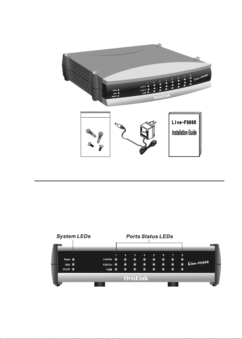
2-2 Preparation before Installation
Fig. 2-1 Package Contents
The Front Panel
The front pa nel is where you can find the LED indicators. For information
concerning LED indicators, please refer to Chapter 5: LED Indicators.
Fig. 2-2 Front panel
Page 15

The Rear Pa nel
The rear panel is where you can locate the eight 10/100Mbps
station ports (MDI-X), one Uplink port and a DC power jack.
For the technical specifications of the ports, please refer to Product
Specifications in Appendix A for detailed inf ormation.
Station Ports (Port #1 to #8)
Use these port to connect to end stations or servers or other network
device.
Uplink-daisy-chain Port
Use this uplink port to connect to a nother hub, switch or other network
device.
DC Power Jack
This is where you should connect to the DC power source.
2-3 Preparation before Installation
Fig. 2-3a Rear panel (with DC5V Power)
Page 16

2-4 Preparation before Installation
Fig. 2-3b Rear panel (with DC7.5V Power)
*The voltage description under the DC power jack might
be either 5VDC or 7.5VDC according to its production
version. A production version higher than or equal to 1.2
will have a DC7.5V instead of DC5V marking. Before you plug in
the power adapter cord, make sure its voltage is correct.
Page 17

Heat Dissipation
On the either side of the Switch, you can find openings that serve as
air vents to expel heated air inside the switch. For proper ventilation of
the switch, please keep in mind that in any ca se these openings should
not be blocked. An adequate margin space for the rear and both sides
of the switch should be provided. Be reminded that without proper air
circulation to dissipate the heat, the internal components of the switch
might get overheated, which might lead to syste m failure.
2-5 Preparation before Installation
Fig. 2-4 Air Openings for heat dissipation
Page 18

Page 19

Installation of the Switch
3
Quick Installation
Live-FSH8R Fast Ethernet Switch is compliant to both 10BASE-T
Ethernet and 100BASE-TX Fast Ethernet standards. It also provides
a n Uplink port to extend your switch-to-switch ca bling distance to 100
meters. Live-FSH8R is not only designed to segment your network
more efficiently, but also to provide a wide range of options to set up
your network connections. It can be used as a simple stand-alone
Switch; or can be connected with standard repeater hubs, switches or
other networking devices in different configurations.
3 Steps to Quick Installation
Step 1.Prepare the network devices to setup a network.
Step 2.Check visually the integrity of the DC power adapter cord to
see if it is in good condition. If it is ready for use, then plug
the female end of the power cord into the DC power jack on
the rear of the switch, and the male end into a power outlet.
Step 3.Connect your network devices (e.g., workstation, server,
switch, bridge or router) to the RJ-45 port (10/100BASE Fast
Ethernet), using a 100 ohm unshielded twisted pair (UTP)
(category 3,4 or 5) or shielded twisted-pair (STP) cable.
Page 20

3-2 Installation of the Switch
Fig. 3-1 Quick installation
Des ktop Installation
Live-FSH8R Fast Ethernet Switch has f our rubber pads attached on
each corner of its underside. These pads serve as cushions against
vibration and prevent the switch from sliding off its position. They
also allow adequate ventilation space when you place the switch on
top of another device.
Fig. 3-2 Desktop installation
Page 21

Installation on W all
Live-FSH8R Fast Ethernet Switch can be mounted on a wall with
wall anchors and screws.
T o mount the Switch on wall, please follow the steps below:
1. Drill two holes, the distance between both of which should be 9
cm (as in a ccordance with the illustration below).
2. Insert wall anchors into these two holes.
3. Drive the screws into the top of the wall anchors.
4. Mount Live-FSH8R on the screws.
3-3 Installation of the Switch
Fig. 3-3 Bottom View of the Switch
(showing mounting holes)
The location you choose to install your switch and the way you
configure your network may greatly affect its performance. The
following sections will provides you with a step-by-step reference to
the following networking requirements:
" Installation site preparation
" Cabling requirements
" Connecting to power
Page 22

3-4 Installation of the Switch
Installation Site Pre paration
You can mount Live-FSH8R Fast Ethernet Switch e ither on a ta ble
or on wall. If you pla n to mount the switch on the table, please choose
a steady , level surfa ce in a well-ventilated area that is free from excessive
dust. In any case, the installation site chosen for your switch has to
comply with the following requirements:
" The surface where you want to mount the switch must be able to
sustain at least the weight of the Switch (450 g).
" Do not place heavy objects on top of the switch.
" The location must preferably be free from excessive dust, away
from heat vent or other warm-air exhaust a nd direct sunlight. The
switch should not be placed near large electric motors or other
electromagnetic equipments. As a reference, the strength of the
electromagnetic field on site should not exceed the (RFC) sta ndards
for IEC 801-3, Level 2 (3V/M) field strength.
" The air temperature in the location should be within a ra nge of 32
to 122 ° F (0 to 55 °C).
" The relative humidity in the location should not exceed 95% non-
condensing humidity.
" The distance between the RJ-45 port and the standard network
interface should not exceed 100 meters.
" Adequate space should be allowed in front of all the ports, so
that each port is easily accessible for cable connections.
Page 23

Cabling Require ments
Live-FSH8R Fast Ethernet Switch fits into the 10 BASE-T/ 100
BASE-TX cabling architecture to facilitate UTP end-station
connections to 10BASE-T/100BASE-TX network. The Uplink port also
provides a switch-to-switch cabling extension up to 100 meters.
The 8 RJ-45 station ports (MDI-X), which require either UTP or
STP cable connection, is compliant with 10/100BASE-TX Fast
Ethernet standard. Thus, when configuring within the 10BASE-T/
100BASE-TX cabling architecture, the UTP ca bling distance should
be within a maximum dista nce of 100m.
RJ-45 station port cable requirements:
""
" 10BASE-T
""
100 Ohm
(UTP/STP ) cable s.
""
" 100BASE-TX
""
100 Ohm
Category 3,4 or 5 unshielded or shielded twisted-pair
Categ ory 5 unshielded twisted-pair (UT P/STP) ca bles.
3-5 Installation of the Switch
Other 10/100BASE-T/TX twisted-pair cable requirement
Under most conditions, the 8 station ports on the Switch may accept
normal, straight-through cables, i.e., standard UTP cables, which are
the only ones that can be used with a RJ-45 pin layout.
In some circumstances, however, cr ossover ca ble s may be r equired
— if a cable is used for a hub or switch connection, the transmit (T D)
a nd receive (RD) leads to one end of the connectors must be reversed
or connected to the uplink port on another hub or switch.
The table below describes what types of cable should be used in
certain circumstances.
Page 24

3-6 Installation of the Switch
T able 3-1 Connections using combinations of station port/Uplink
Daisy-chain port and straight-through/crossover cable
10/100BASE-T/TX networks require a 4-pair, data grade UTP/STP
cabling system. The cabling system could be found in most existing
network installations. The pin assignments f or a straight-through ca ble
are shown in Figures 3-4 a nd 3-5.
Fig. 3-4 Pin assignments for straight-through cabling
Page 25

Fig. 3-5 RJ-45 connector pin assign ments
Connecting to Power
3-7 Installation of the Switch
Live-FSH8R is accompa nied with a n external power a da pter unit, which
is specifically designed for the line voltage and the type of AC outlet
used in your location. This power adapter provides the voltage,
amperage, a nd polarity required by the Switch (5VDC@2A or 7.5VDC@1.5A,
inside positive, outside negative) and is outfitted with the correct
type of barrel connector for the Switch’s DC power jack.
After verifying that the DC power adapter cord is suitable for use,
just plug the male end of the DC power adapter into a power outlet
on the wall; and plug the barrel connector of the power adapter into
DC power jack on the Switch. Once you have correctly plugged in the
power, the Switch is activated. (Meanwhile the Switch will perf orm a
Power-on Self-test, as you can see the LEDs light up for about 3
seconds during this test).
Page 26

3-8 Installation of the Switch
Fig. 3-6a Connecting to power adapter with correct voltage (DC5V)*
Fig. 3-6b Connecting to power adapter with correct voltage (DC7.5V)*
*The DC input voltage might be either 5VDC or 7.5 VDC according to
its production model. Production version 1.2 or higher adopts
7.5VDC instead of 5VDC. Before you plug in the power adapter cord,
make sure its voltage specification is the same. For the volage of
the switch, you can verify the voltage marking under the power jack
on the rear panel.
Page 27

Expanding Your Network
4
Live-FSH8R Fast Ethernet Switch not only is targeted as a
concentrator to converge LAN traffic within your Ethernet/Fast
Ethernet network, but also as an efficient switching device to send
incoming data to its destination LAN segment. With your existing
Ethernet infrastructure, you can very easily connect, expand or migrate
to an Ethernet/Fast Ethernet environment.
The following sections will introduce to you the basics of network
connectivity within Ethernet/Fast Ethernet environment.
Connectivity Rule s
Ethernet (10 Mbps)
Ethernet (10Mbps) networks should be configured according to the
following connectivity rules:
" The maximum length for UTP cables must not exceed 100 meters
from end station to a shared-access 10Base-T hub.
" Between any two end stations in a collision domain, there may
be up to five cable segments and four intermediate repeaters at
most.
" If there is a path between any two end-stations containing five
segments and four repeaters, then at least two of the cable
segments must be point-to-point link segments (e.g. 10BASE-T,
10BASE-5), while the remaining segments may be of mixed
segments (e.g. 10BASE-2 or 10BASE-5).
Page 28

4-2 Expanding Your Network
Fast Ethernet (100 Mbps)
Fast Ethernet (100Mbps) network should be configured according to
the following connectivity rules:
" The maximum length for UTP cables is 100 meters from end
station to a shared-access 100BASE-TX hub.
" In a single collision domain with two repeaters, the maximum
cabling length is 100 meters between an end station and a
repeater, and 100 meters between two switches, thus making a
maximum diameter of 300 meters between two end stations.
Switch-to-Hub Connection
Live-FSH8R Fast Ethernet Switch can be connected to a
10Base-T or 100BASE-TX hub vi a a 4 -pair UTP / STP straightthrough cable (Category 3, 4 or 5). Ea ch cable length can be up
to 100 meters long (328 feet). The switch-to-hub connection
can be made through the Uplink daisy-chain port (MDI-II) on
the hub to any of the station ports (MDI-X) on Live-FSH8R.
For a 10BASE-T or 100BASE-TX hub connection, the LED indicators
on the Switch should give the following signals to indicate a proper
and functional connection:
""
" Link/Act LED indicator should be ON
""
""
" FDX/Col LED status will depends on the status of the other
""
connected hub or device
""
" 100 M LED indicator should be ON if connected to 100BASE-
""
TX device, otherwise it should be OFF
Both 10BASE-T and 100BASE-TX network environments
allow uplinking, but each follows different rules for
connection.
Page 29

4-3 Expanding Your Network
Switch-to-switch (Other Device) Connection
Live-FSH8R Fa st Ethernet Switch ca n be connected to another switch
or other networking device such as a router or bridge by a two-pair
UTP / STP Straight-through or Crossover cable (Category 3, 4, 5).
Using a Straight-through Cable
When using a straight-through cable, the switch-to-switch connection
is done through the Uplink daisy-chain port (MDI-II) of the Switch
to any of the 10Mbps or 100Mbps station port (MDI-X) of another
switch or device.
Using a Crossover Cable
When connecting any 10/100 Mbps station port (MDI-X) of other
switch or device to any station port (MDI-X) of Live-FSH8R Fast
Ethernet Switch, it is required that you use a crossover ca ble.
The LEDs on Live-FSH8R Fast Ethernet Switch corresponding to
the respective connected port should give the following signals to
indicate a proper and functional connection:
""
" Link/Act LED indicator should be ON
""
""
" FDX/Col LED status will depends on the status of the other
""
connected switch or device
""
" 100M LED indicator should be ON if connected to 100BASE-
""
TX connection, otherwise it should be OFF
Connecting with a Switch (or Hub) without Uplink Port
If the switch (or hub) to be connected to Live-FSH8R Fast Ethernet
Switch is without an Uplink daisy-chain port (MDI-II), a switch-to-
switch connection can still be made using either a straight-through
cable or a crossover cable.
Page 30

4-4 Expanding Your Network
Using Straight-through Cable Connection
When using a straight-through cable, the connection can be made
through the Uplink daisy-chain port (MDI-II) of the Switch to any
station port (MDI-X) of the other switch or hub.
Fig. 4-1 Connection through Uplink Port using straight-
through cable
Using Crossover Cable connection
When using a crossover cable, the switch-to-switch connection can
be made from any station port (MDI-X) of Live-FSH8R Fast Ethernet
Switch to any station port (MDI-X) of the other switch or hub.
Page 31

4-5 Expanding Your Network
This requirement differs somehow from the switch-to-node
connection. For the pin assignments of crossover cabling please
refer to Fig 4-3.
Fig. 4-2 Connection through Station Port using
crossover cable
Do not plug a phone jack connector into any RJ-45 port.
This may damage the port. Inste ad, use only twisted-pair
cable with RJ-45 connector that conforms with FCC
standards
Notes:
1. Port #1 is shared with the Uplink daisy-chain port, although their
pinouts are different. Do not use both port #1 and the Uplink Port
(MDI-II) at the same time.
2. Make sure each twisted-pair cable does not exceed 100 meters.
3. To connect to another switch or hub, you may make a connection
with station ports (MDI-X) at both ends if you use crossover cable.
Page 32

4-6 Expanding Your Network
RJ-45 Port Description
RJ-45 station ports (MDI-X) can be attached to any devices, which use a
standard network interface (e.g., a workstation, server, bridge or router).
But the Uplink daisy-chain port (MDI-II) can be cascaded to a station
port on similar networking devices (e.g. another switch or hub).
When cascading multiple switches (or hubs), it is important that the UTP
cables should be of crossover type as shown in the diagram above. Also,
make sure you use the same pair of wire for pin pairs 1-2,3-6,4-5 and 7-
8.
Fig. 4-3 Pin assign ments for crossover cabling
The wire schematics for both straight-through and crossover twistedpair cables are shown as below:
Fig. 4-4 Wire schematics for straight-through and
crossover cable.
Page 33

Summary :
" When connecting a computer to a switch, use a straight-through
UTP cable .
" When connecting from the Uplink port (MDI-II) of Live-FSH8R
to a ny station port (MDI-X) of another hub, use a straight-thr ough
UTP cable. Plea se note that the ca bling distance limit is 100 meters
maximum.
" When connecting from a ny station port (MDI-X) of Live-FSH8R
to any station port of other devices, use a crossover cable.
T ra n smission Mode
All 10/100Mbps ports of Live-FSH8R Fast Ethernet Switch utilize
auto-negotiation to determine the transmission mode for any new
connection. This means, if auto-negotiation is supported on both ends
of the connection, the Switch is initiated to negotiate for one of the
following transmission modes:
4-7 Expanding Your Network
" 200Mbps/FDX
" 100Mbps/HDX
" 20Mbps/FDX
" 10Mbps/HDX
Applications
Gear Up Network Performance for SOHO Networking
Live-FSH8R Fast Ethernet Switch serves primarily as a concentrator
to converge your SOHO network traffic, and as a highly efficient
switching device to forward the incoming data to its destination
network segment. With its auto-sensing and –negotiating functions,
it makes your mixed Ethernet/Fast Ethernet networking environment
as efficient and compatible. Not only ca n you expand or upgrade from
10Mbps to 100 Mbps Fast Ethernet bandwidth with
Page 34

4-8 Expanding Your Network
virtually no effort, but also your existing Ethernet investment are saved
for your leverage. It is a perfect solution to cater to SOHO users’ later
network expansion needs. With its Uplink Port, Live-FSH8R is
extremely flexible in network configuration. Through uplinking multiple
switches, hubs or other devices, plenty of flexibility and expandability
is left for the SOHO users to apply in future LAN configuration and
expansion.
Since Live-FSH8R provide such a cost-effective way to gear up your
SOHO network performance, you will appreciate the easy Plug-and-
Play installation within your SOHO network.
Fully compatible with either 10/100 Mbps connection in either half/
full duplex tra nsmission mode, Live-FSH8R ca n ea sily connect devices
with different transmission speeds. You can rely on Live-FSH8R to
serve as an effective switching device for your SOHO network.
Live-FSH8R Fast Ethernet Switch can significantly improve your
network performance through effectively segmenting your network
traffic. The result is an increasing bandwidth and throughput that can
be experienced by LAN users. Either of the 8 station ports of Live-
FSH8R can be attached to a hub (i.e., shared collision domain) or
serve as a dedicated link to a single network device (e.g., a workstation).
When a port on the Switch is connected to an Ethernet hub (i.e., a 10
or 100 Mbps repeater), the bandwidth provided by that port is shared
by all the devices connected to the attached hub. However, when a
port is connected to an end node or to a device that breaks up the
collision domain (e.g., a nother Switch, bridge or router), the attached
device has access to the full bandwidth provided by that port.
Microsegmentation of an existing LAN can improve network latency
a nd increase overall performance.
Live-FSH8R Fast Ethernet Switch also uses Store-and-Forward
switching to manage network traf fic, thus ensuring data integrity under
heavy load.
Page 35

4-9 Expanding Your Network
With such versatility and flexibility plus a very cost-effective a nd ea sy
installation, you will appreciate Live-FSH8R as your best choice for
easy migration to a 100 Mbps Fast Ethernet network yet preserving
your existing 10 Mbps network architecture.
For details on the cabling requirements, please refer to Chapter 3
a nd 4.
Since it is very possible that your SOHO network will expand to a
considerable size along with your business expansion, you might wish
to accommodate your future expansion need with your Live-FSH8R.
In fact, we can envision a “more sophisticated” network expansion
from your SOHO network as seen in Fig. 4-5. As you can see, users of
Live-FSH8R are still left with a great expandability for future network
growth.
Fig. 4-5 Microsegmentation of a “more sophisticated”
SOHO Network
Page 36

Page 37

LED Indicators
5
T
he front-panel LED indicators enable users of Live-FSH8R Fast
Ethernet Switch to monitor the Power On/Off status and the func-
tional status of the Switch as well as the port status of each of its eight
10/100 Mbps station ports. For the layout of LED indicators, please
refer to Fig. 5-1 below.
As seen on Fig. 5-1, the Power LED indicates the power on/off
status of the switch. The DIAG LED shows the functional sta-
tus of the Switch. The ENLOOP LED warns for the existence
of a network loop. For each station port, there are Link/Act
(Link/Activity), FDX/Col (Full-duplex) and 100M LED to indi-
cate its corresponding port status. You’ll find the LED indicators
to be a very convenient way for switch or port status monitoring
a nd troubleshooting.
Before connecting any network device to Live-FSH8R Fast Ethernet
Switch, you should take a few minutes to look over this section and
get familiar with the front panel LED indicators of your Switch.
Fig. 5-1 LED indicators
Page 38

5-2 LED Indicators
LED Status during Power-on Self-test
If the network and power source has been properly established, you
are now ready to a ctivate your Switch. While first turning on the switch,
Power LED light is on to indicate the Switch is activated. Meanwhile,
all station port LEDs such a s Link/Act, FD X/Col, a nd 100 M LEDs will
blink about 3 seconds. During this brief period, the Switch is perf orming a auto-checking on LEDs to ensure they can function properly.
The flashing duration for LEDs is determined by the RC value.
After the Power-on Self-test is over, the Power LED will remain lighted
as long as the Switch is not turned off, while port status LEDs (Link/
Act, FDX/Col, and 100 M LEDs) will begin to function and give specific information on corresponding port status.
Power LED
Power LED will give a steady green light when you turn on the
Switch, and will be off when the Switch being turned off. You can
simply check the Power LED status to see if the Switch is being
activated or not. Before turning on the Switch, please verify that the
power cord has been properly connected the Switch to the power
outlet on the wall.
Fig. 5-2 Power-On LED test
Page 39

DIAG LED
The DIAG LED provides you with diagnostic information about the
functional status of Live-FSH8R. When the Switch functions normally,
the DIAG LED is of f. A constant blinking DIAG LED indicates either
internal memory check has failed. Normally , this LED should always be
off to indicate a normal system status. If you do find the Status LED
keeps blinking persistently, it indicates a possible hardware
malfunction. To troubleshoot the problem, just turn off the system
power for a few seconds and then turn on again in an attempt to reset
the system back to normal. However, if this problem still persists and
the blinking yellow light of the DIAG LED won’t go of f, plea se conta ct
your local dealer for technical support.
ENLOOP LED
The ENLOOP LED indicates the existence of a network loop when the
loop detection function is enabled on the Switch*.
5-3 LED Indicators
Port Status LEDs (Port 1 to Port 8)
##
# Link/Act LED
##
When a port is operating with auto-negotiation to run in full
duplex mode, its corresponding Link/Act LED will show a
blinking green light indicating a data link being established
between the port and the device. This is because, in full duplex
mode, the Switch will send a P AUSE pa cket to indicate the transmitter to start sending packets. Thus, the Link/Act LED will
remain blinking to indicate this state in full duplex mode, no
matter the port is transmitting or receiving packets or not.
Conversely, when in half duplex mode, the Link/Act LED will
* The Loop detection function is currently disabled on the Switch.
Page 40

5-4 LED Indicators
##
# FD X/Col LEDs
##
FDX/Col LED shows the transmission mode as well as the
remain steady gr een when connection is made. But it will blink
only when the port is transmitting or receiving data. If you’ve
made a connection with a port but the corresponding Link/Act
LED has no due response as expected, you should check whether
the RJ-45 connector is damaged, or the cable type or pin-out is
not correct, or the cable length exceeds the 100 meter li mit.
presence of collision on the network.
When in full-duplex tra nsmission mode, FD X/Col LED gives
forth a solid yellow light. When in half-duplex mode, it will be
off. But, when in half-duplex mode, there are two or more end
stations on the same network segment attempting to transmit
data at the same time, a collision occurs. If there is a collision
detected on specific network segment, the corresponding FDX/
Col LED shows a blinking yellow light. When a collision
occurs, all of the stations involved will recognize the collision,
wait a ra ndom a mount of time, and retransmit.
FDX/Col LED status is summarized a s follows:
" ON :Tra nsmission in full-duplex
" OFF:Transmission in half-duplex
" Blinking :Collision detected
##
# 100 M LED (Transmission Speed Indicator)
##
100M LED showing a steady red light indicates that the line
speed going through that specific 10/100 Mbps port is operating
at 100Mbps mode. If the transmission speed operates only at
10 Mbps, it is off.
Page 41

5-5 LED Indicators
A summary of the station-port LED status is listed in Table 5-1
below:
Table 5-1 LED Port Status
Page 42

Page 43

Appendix A
Product Specification s
Sta ndard Compli ance - IEEE 802.3 10BASE-T
Ethernet
- IEEE 802.3u 100BASE-TX Fast
Ethernet
- ANSI/IEEE Std 802.3 Nway
auto-Negotiation
- IEEE 802.3 Frame Type:
Transparent
Topology Star
Protocol CSMA/CD
Port Configuration 8 × 100 BASE-TX Ports
1 × Uplink Port
Data rate Ethernet
10 Megabit/sec (half-duplex)
20 Megabit/sec (full-duplex)
Fa st Ethernet
100 Megabit/sec (half-duplex)
200 Megabit/sec (full-duplex)
Cabling 100BASE-TX
4-pair 100
or STP (100 m) cable
Ohm
Category 5 UTP
Page 44

Appendix A Product Specifications
T ransmission Method Store and forward
Full Duplex Auto-negotiation
RAM Buffer 256 Kbytes per device
Minimum latency 4.5 Micro-Sec
Active Flow Control - IEEE 802.3x compliant flow
Filtering Address Table 8 K per device
10BASE-T
4-pair 100 Ohm Category 3,4,5
UTP (100 m) cable
control for full duplex
- Back Pressure option for half
duplex
Packet Filtering/ Wire speed for 10/100Mbps
Forwarding Rate
MAC Address Learning Automatic update
LED layout System Status LEDs
- Power LED
- DIAG LED
- ENLOOP LED
Station port LEDs
- Link/Act LEDs
- FDX/Col LEDs
- 100 M LEDs
*
* The Loop detection function is currently disabled on the Switch.
Page 45

Appendix A Product Specifications
Dimensions (L x W x H) 209 x 144 x 49 m/m
Net Weight 450 g
Power Input* External Power Supply
with +5V
+7.5V
DC @2A or
DC @1.5A output
Power Consumption* 7.5 Watts max @5V
DC / 7.5VDC
Operating Temperature 32 ~ 122 °F / 0 ~ 50 °C
Storage Temperature - 4 ~ 158
°F / -20 ~ 70 °C
Humidity < 95% (non-condensing)
EMI FCC Class A, CE mark
*The DC input voltage might be either 5VDC or 7.5 VDC according to
its production model. Production version 1.2 or higher adopts
7.5VDC instead of 5VDC. Before you plug in the power adapter cord,
make sure its voltage specification is the same. For the volage of
the switch, you can verify the voltage marking under the power jack
on the rear panel.
Page 46

Appendix B
Troubleshooting
This appendix contains information to help you identify a nd solve problems.
If your switch does not function properly, please make sure it is set up
according to the instructions on the manual.
If you suspect your switch is not connected correctly to your network,
check the following points before you conta ct your local dealer for support.
" Make sure that the maximum cable length between switch and end
node does not exceed 100 m.
" Make sure that the maximum repeater-to-re peater cable dista nce doe s
not exceed 205 meters.
" Verify that the cabling type used is correct (Category 5 UTP).
" Check the Link/Act LED lights on the front panel to see if it lights
up. If it does not light up, that means a faulty connection. Check
the status of the cable attachment. If the problem persists, try a
different cable.
" Check the DIAG LED to see if it is blinking. If it blinks persistently ,
that means the internal memory check has failed.
" Try another port on the Switch.
" Turn off power supply to the Switch. After a while, turn it on again
to see if it resumes to its normal function.
" Utilize the LED information to troubleshoot your problem. Please
refer to Chapter 5 LED indicators.
If you find out where the problem is but can not solve it by yourself, or
you simply cannot locate what is at fault, please conta ct your local dealer
for technical support.
 Loading...