

Page 1

Live-FSH16T Live-FSH16T Live-FSH16T Live-FSH16T Live-FSH16T
Live-FSH16T Live-FSH16T Live-FSH16T Live-FSH16T Live-FSH16T Live-FSH16T
Live-FSH16T Live-FSH16T Live-FSH16T Live-FSH16T Live-FSH16T
Live-FSH16T Live-FSH16T Live-FSH16T Live-FSH16T Live-FSH16T Live-FSH16T
Live-FSH16T Live-FSH16T Live-FSH16T Live-FSH16T Live-FSH16T
Live-FSH16T Live-FSH16T Live-FSH16T Live-FSH16T Live-FSH16T Live-FSH16T
Live-FSH16T
Fast Ethernet Switch
16 × 10/100Mbps + 1 × Uplink port
NWay 10/100BASE-TX
Fast Ethernet Switch
with Priority Function
User’s Manual
Rev. Live-FSH16T V.1.0
Published: July 18, 2001
Copyright © OvisLink Corp.
1
Page 2

Trademarks
All rights reserved.
OvisLink and OvisLink Logo are registered trademarks of Ovis Link Corp. Other product
and company names trademarks or registered trademarks of their respectiv e companies.
Contents in this manual are subject to changes without prior notice.
FCC Warning
This equipment has been tested and found to comply with the requirements for a Class A
digital device, pursuant to Part 15 of the FCC Rules. These requirements are designed for
reasonable protection against harmful interference when the equipment operating in a
commercial environment. This equipment can generate and radiate electromagnetic energy
and, if not installed and used in accordance with this guide, may cause significant
interference with radio communication. Operation of this equipment in a residential area is
likely to cause interference to household appliances, in which case the user will be required
to amend at his or her own expense.
CE Mark Warning
This is a Class A product. In a domestic environment, this product may cause radio
interference, in which case the use r may be required to take adequa te preventive me asures.
2
Page 3

About
About tttthis
About About
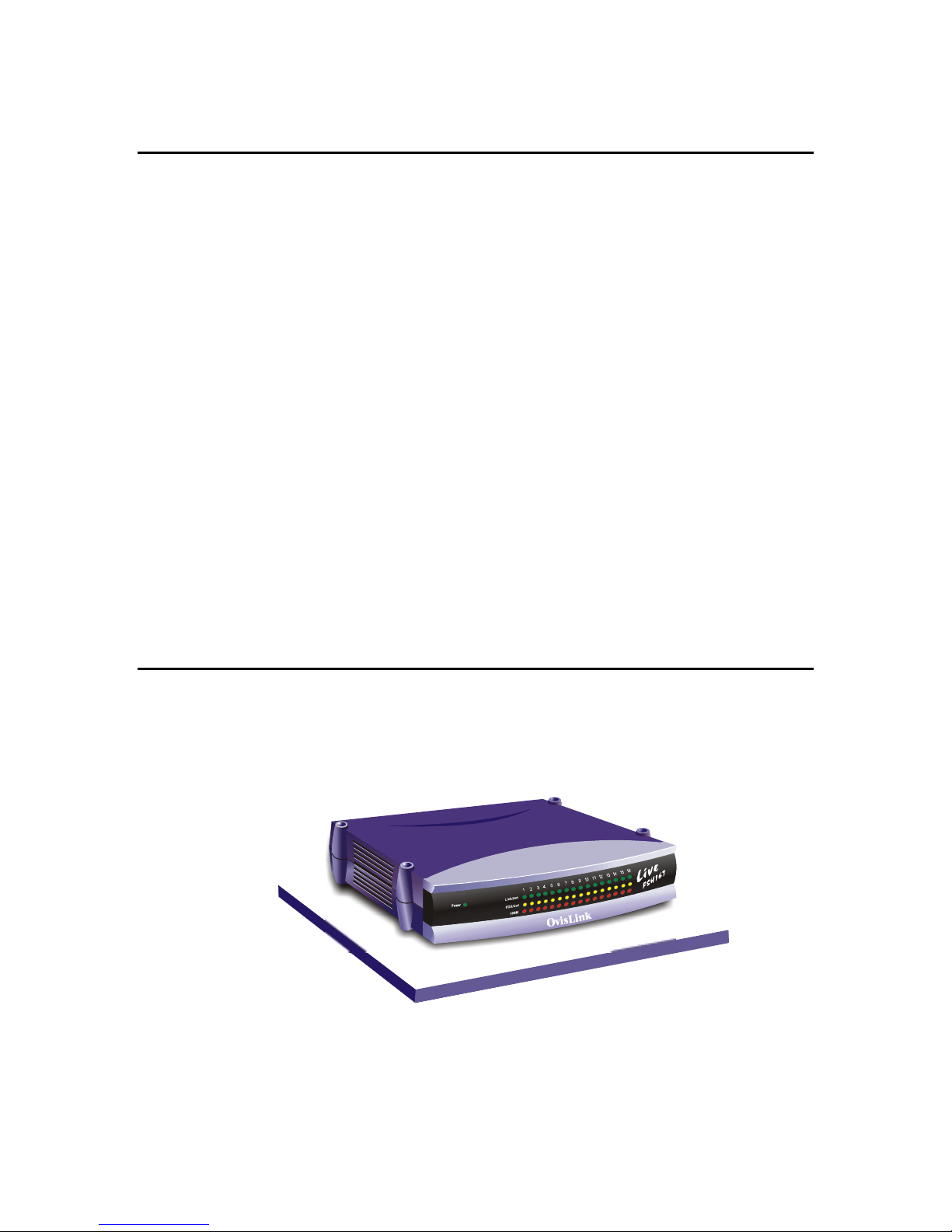
This User’s Manual aims at helping users to know the key features of
Live-FSH16T Fast Ethernet Switch and to install it in a 10/100BASE-TX
Fast Ethernet Local Area Network (LAN).
his User
his his
User’’’’s Manual
UserUser
s Manual
s Manuals Manual
3
Page 4

Table of Contents
PRODUCT OVERVIEW........................................................................ 8
Introduction.......................................................................................................................8
16-port 10/100 Mbps Fast Ethernet Switch.....................................................................8
Easy Plug-and-Play.........................................................................................................8
Cost-effective for LAN Users.........................................................................................8
Store-and-Forward Architecture against Packet Loss.....................................................9
Active Flow Control........................................................................................................9
Port Status Information at a Glance ................................................................................9
What is 10/100 Mbps Dual-Speed Switching?................................................................9
What is Priority Queuing? .............................................................................................10
Product Features.............................................................................................................11
PREPARATION BEFORE INSTALLATION.............................. 12
Unpack the Package........................................................................................................12
The Front Panel...............................................................................................................13
The Rear Panel................................................................................................................13
Station Ports (Port #1 to #16)........................................................................................13
Uplink Port....................................................................................................................14
DC Power Jack..............................................................................................................14
4
Page 5

INSTALLATION OF THE SWITCH ............................................ 15
Quick Installation............................................................................................................15
3 Steps to Quick Installation .........................................................................................15
Installation Site Preparation..........................................................................................16
Desktop Installation........................................................................................................16
Installation on Wall.........................................................................................................17
Cabling Requirements....................................................................................................17
RJ-45 station port cable requirements...........................................................................18
Other 10/100BASE-T/TX twisted-pair cable requirement ...........................................18
Connecting to power.......................................................................................................19
EXPANDING YOUR NETWORK........................................................ 21
Connectivity Rules...........................................................................................................21
10 Mbps Connection .....................................................................................................21
100 Mbps Connection ...................................................................................................21
Hub-to-Switch connection ..............................................................................................22
Switch-to-switch Connection..........................................................................................22
Using a Straight Cable...................................................................................................22
Using a Crossover Cable............................................................................................... 23
RJ-45 Port Description..................................................................................................23
Summary .......................................................................................................................24
Transmission Mode.........................................................................................................24
Using Priority Ports ........................................................................................................25
Applications.....................................................................................................................25
LAN Microsegmentation...............................................................................................25
Easy Migration to Workgroup Computing....................................................................26
5
Page 6

Priority Queuing............................................................................................................27
LED INDICATORS.............................................................................. 28
Power LED.......................................................................................................................28
Station-port LEDs...........................................................................................................28
Link/Rx LED.................................................................................................................28
FDX/Col LEDs..............................................................................................................29
100 M LED....................................................................................................................29
APPENDIX A..................................................................................................... 30
Product Specifications.....................................................................................................30
APPENDIX B..................................................................................................... 32
Troubleshooting...............................................................................................................32
Tables
Table 3-1: Using straight-through and crossover cables............................................... 18
Table 5-1: LED signals .................................................................................................29
Figures
Fig. 2-1 Package Contents.............................................................................................12
Fig. 2-2 Front Panel......................................................................................................13
Fig. 2-3 Front Panel......................................................................................................13
Fig. 3-1 Quick Installation ............................................................................................15
Fig. 3-2 Desktop installation.........................................................................................16
Fig. 3-3 Bottom View of the Switch (showing mounting holes)..................................17
Fig. 3-4 RJ-45 connector pin assignments.................................................................... 19
Fig. 3-5 Pin assignments for straight-through cabling.................................................19
Fig. 3-6 Connecting the Switch to power outlet............................................................20
6
Page 7

Fig. 4-1 Connection through Uplink Port using straight-through cable.....................22
Fig. 4-2 Connection through Station Port using crossover cable................................23
Fig. 4-3 Pin assignments for crossover cabling.............................................................24
Fig. 4-4 Wire schematics for straight-through and crossover cable.............................24
Fig. 4-5 Microsegmentation in a LAN group................................................................26
Fig. 5-1 LED indicators.................................................................................................28
7
Page 8

Product Overview
Introduction
16-port 10/100 Mbps Fast Ethernet Switch
Live-FSH16T Fast Ethernet Switch is a 16-port auto-sensing and auto-negotiating
Dual-speed Fast Ethernet Switch with Port Priority function. All of its 16 RJ-45 station
ports support Dual Speed with auto-sensing and auto-negotiating functions. All 16 station
ports can automatically adapt to data rates ranging from 10 Mbps (Ethernet half-duplex
mode) to 200 Mbps (Fast Ethernet full-duplex mode).
Live-FSH16T also features port priority function that is implemented via built in
priority port (port 5, 6, 7 and 8). You can instantly utilize priority function by
plugging into these ports without further configuration. Priority port can ensure high
priority traffic to be delivered efficiently, even when during bursts of high traffic load.
Traffic such as voice data and video (services which are streaming) are thus prioritized,
helping steady pic ture and sound qua lity. Ple ase refer to the Us ing Prio rity Ports section i n
Chapter 4.
The Uplink port is provided for connection with another switch with straight-through
cable. With its Uplink port, you can connec t two sw i tch es to g ether to re ach a maximum of
48 ports. With auto-sensing function, Live-FSH16T Fast Ethernet Switch automatically
detects the speed of the devices you plug into, and routes the incoming data to its
destination. Its auto-neg otiating function also al lows exist ing devices with di fferent speeds
to communicate easily within the same network.
With these advantages, you have no further costs for hardware investment in unnecessary
or expensive upgrade.
Easy Plug-and-Play
Live-FSH16T Fast Ethernet Switch fully complies with the IEEE802.3 standard for
10BASE-T network and the I EEE802.3u standard for 100BASE- TX network . And it tak es
users almost no effort to install. Simply plug in the power and connect devices to its ports
and you just complete its installation. With its easy Plug-and-Play installation procedure,
Live-FSH16T Fast Ethernet Switch costs you virtually no effort to install and run.
Cost-effective for LAN Users
Live-FSH16T Fast Ethernet Switch is your best choice for a cost-effective solution to
8
Page 9

expand, connect or upgrade your existing 10 Mbps Ethernet to 100 Mbps Fast Ethernet
network. With the implementation of Live-FSH16T Fast Ethernet Switch, it means that
your existing 10 Mbps Ethe rnet netwo rk can be ex tend ed to Fast Ether net 100 Mb ps speed
at very effective costs.
Store-and-Forward Architecture against Packet Loss
It is recognized that when network is under heavy traffic, the shared memory buffer in the
switching devices might yield incorrect detections due to an overfed memory buffer. This
drawback in transmission can happen either when data being transmitted in IEEE802.3x
Full Duplex or Back Pressure Flow Control mode. To amend this problem, Live-FSH16T
Fast Ethernet Switch utilizes a fixed memory buffer allocation with Store-and-forward
transmission to ensure an effective buffer allocation for each port. Store-and-forward
transmission controls data flow from transmitting to receiving nodes with the receiving
buffer threshold adjusted to optimal value, guaranteeing against all possible packet losses.
Active Flow Control
Live-FSH16T Fast Ethernet Switch implements in full duplex mode a flow control which
is compliant to IEEE 802.3x standard. While in half duplex mode, it employs an optional
Back Pressure Flow Control to stall the incoming data when port buffers being saturated.
With this flow control mechanism, it can be ensured that frames dropped during
transmission are reduced to a minimum.
Port Status Information at a Glance
The LED indicators on the front panel show relevant information of your network status.
Power LED indicates the Power On/Off status. Each Link/Rx LED indicates the linking
and receiving status of each port, while FDX/Col LED shows the half-duplex/full-duplex
transmission status and collisions within network. 100 M LED indicates the connection is
running at 100 Mbps mode. For detai led LED info rmation, please refer to Chapt er 5, LED
indicators.
What is 10/100 Mbps Dual-Speed Switching?
Current expansion of multimedia usage on the network, together with the new wave of
distributed Client/Server applications, creates a much higher demand for bandwidth and
tighter integration of clients and servers. The legacy shared-access 10Mbps Ethernet
technology can no long er provide adequ ate bandwidth and pred ictable respo nse tim e to the
new workgroup environment.
10/100 Switching is an integral extension of Fast Ethernet. It provides not only the
100Mbps high-speed “pipeline” for carrying aggregated 10Mbps traffic, but also the
necessary bridging between the 10BASET and 100BASE-T MAC formats.
Fast Ethernet combined with the Switching technology offers an adequate bandwidth to
satisfy the demand of local workgroups. It also provides a high-speed link to carry local
network traffic elsewhere within a network. Ethernet switching technology dramatically
boosts the total bandwidth performance of a LAN network. It also furnishes configuration
9
Page 10

flexibility and bandwidth adaptability for the local workgroups where the majority of
workload is generated by business applications.
Switching function further eliminates the congestion problem inherent to the
contention-based CSMA/CD proto col, the reby improving predictable re spons e ti me under
heavy load. While in the past, this network congestion could only be alleviated by much
more expensive routing technology. With the implementation of switching technology,
Live-FSH16T Fast Ethernet Switch is your perfect solution to solve network congestion.
What is Priority Queuing?
Priority Queuing is a method of ens uring that hig h priority traffic get s delivered effi ciently,
even when during bursts of high traffic load. In this way, traffic such as voice data and
video (services which are streaming) are prioritized, helping steady picture and sound
quality.
If you have any plans to implement network telephony or any sort of video conferencing,
streaming video/audio or any real-time applications on your network you will need
Live-FSH16T for priority queuing. The benefit of priority queuing is that it can
dramatically improve the quality of priority services on the network. If priority queuing is
not implemented then the qual ity of these servic es will depend enti rely on the load on your
network. If network traffic is high, the service will not work properly.
10
Page 11

Product Features
The main features of Live-FSH16T Fast Ethernet Switch are as follows:
Ideal for workgroup environment in Fast Ethernet network
Easy migration from existing 10 Mbps Ethernet network to 100 Mbps Fast Ethernet
network
Cost-effective to connect an d expand your ex isting 10 Mbps Ethernet network to 1 00 Mbps
Fast Ethernet networking environment
Easy installation without further maintenance costs
Plug-and-play function saving network management efforts
Best Choice to protect your previous network hardware investment
Full compatibility with Standard and Fast Ethernet:
- IEEE 802.3u (100 BASE-TX Fast Ethernet)
- IEEE 802.3 (10 BASE-T Ethernet)
- IEEE 802.1p Class of Service (Priority Queuing)
- ANSI/IEEE Std 802.3 Nway auto-negotiation
Flexible port configuration:
- 16 × 10/100 Mbps auto-sensing and auto-negotiating ports
- 1 × Uplink Port
Store and Forward transmission to prevent packet loss
Priority ports: Port 5, 6, 7 and 8
Prioritization sources: Port-based Priority
Priority level: High/Normal
Store and Forward transmission to prevent packet loss
Half/Full Duplex function for all stations ports and Uplink port
Auto-sensing and auto-negotiating function for all station ports and Uplink port
Active Flow control to minimize frame drops
- Half Duplex: Back Pressure control
- Full Duplex: IEEE 802.3x compliant flow control
LED indicators for port status monitoring:
- Power LED (green) to indicate power on/off status
- Link/Rx (green) to indicate Linking status and activity
- FDX/Col (yellow) to indicate Full/half duplex transmission mode and collisions
- 100 M LED (red) to indicate 10/100 Mbps speed
Cabling distance between switches extensible to 100 meters through the Uplink port
(shared with port 16)
11
Page 12

Preparation before Installation
Unpack the Package
Before you begin the installation of Live-FSH16T Fast Ethernet Switch, make sure that you have all
the necessary components that come with your package. Follow the steps below to unpack your
package contents:
Step 1. Clear out the surrounding area for an adequate space to unpack the package carton.
Step 2. Open the shipping carton and take out the package contents carefully.
Step 3. Put back all the shipping materials such as plastic bag, paddings and linings into the
shipping carton and save them for possible future transport need.
After unpacking and taking out all the components, you should check your package contents to see
if you’ve got all the following items:
Live-FSH16T Fast Ethernet Switch
One DC power Adapter
Wall-mounting kit (screws and wall-anchors)
This User’s Manual (can be found on Support CD-ROM)
Quick Start Guide
If any of these components is missing or damaged, please con tact y our local dealer for replacem ent.
Fig. 2-1 Package Contents
12
Page 13

The Front Panel
The front panel is where you can find the LED indicators. For information concerning
LED indicators, please refer to Chapter 5, LED Indicators.
The Rear Panel
The rear panel is where y ou can locate the DC po wer jack, the 16 10/100Mbp s statio n
ports and 1 Uplink port. For the technical specifications of the ports, please refer to
Product Specifications in Appendix A, Product Specification for detailed information.
DC Power Jack Station Ports
Station Ports (Port #1 to #16)
Live-FSH16T Fast Ethernet Switch is equipped with 16 10/100Mbps auto-sensing and
auto-negotiating ports. You can use these ports to connect to end stations, servers or other
networking devices.
LED Indicators
Fig. 2-2 Front Panel
Station Ports
Priority ports: port 5, 6, 7 and 8
Fig. 2-3 Front Panel
13
Page 14

Uplink Port
The Uplink port allows connection to another hub, switch or other network device using a
straight-through cable.
DC Power Jack
The DC Power Jack is where you should connect the DC power adapter chord.
14
Page 15

Installation of the Switch
Quick Installation
Live-FSH16T Fast Ethernet Switch is compliant to both 10BASE-T Ethernet and
100BASE-TX Fast Ethernet standards. It also provides an Uplink port to extend your
switch-to-switch cabling distance to 100 meters. Live-FSH16T Fast Ethernet Switch is
primarily targeted as an ideal solution to enhance your workgroup performance in an
Ethernet/Fast Ethernet network.
3 Steps to Quick Installation
Step 1. Prepare the network devices you wish to setup a network.
Step 2. Check visually the i ntegrity of the power c ord to see if it is in good condi tion. If the
power cord is ready for use, then plug the female end of the power cord into the co nnector
on the rear of the switch, and the male end into a power outlet.
Step 3. Connect your network devices (e.g., workstation, server, switch, bridge or router)
to the RJ-45 port (10/100BASE Fast Ethernet), using a 100 unshielded twisted pair (UTP
Cat 3,4 or 5) or shielded twisted-pair (STP) cable.
Fig. 3-1 Quick Installation
15
Page 16
Installation Site Preparation
You can mount Live-FSH16T Fast Ethernet Switch ei ther on a table or on wall. I f you plan
to mount the switch on the table, please choose a steady, level surface in a well-ventilated
area that is fre e from excess ive dust. I n any case, the instal lation site chosen for y our switch
has to comply with the following requirements:
The surface to mount the switch must be able to sustain the weight of the switch.
Do not place heavy objects on top of the switch.
The location must preferably be free from excessive dust, away from heat vent or
other warm-air exhaust and direct sunlight.
The switch should not be placed near large electric motors or other
electromagnetic equipments. As a reference, the strength of the electromagnetic
field on site should no t exceed th e (RFC) standards for IE C 801-3, Level 2 (3V/M )
field strength.
The air temperature in the location should be within a range of 32 to 122 ° F (0 to
55 °C).
The relative humidity in the location should not exceed 95% non-condensing
humidity.
The power outlet should be located within 6 feet from the device.
The distance between the R J-45 port and the standa rd network in terface should no t
exceed 100 meters.
Adequate space should be allowed in front of all the ports, so that each port is
easily accessible for cable connections.
Desktop Installation
Live-FSH16T Fast Ethernet Switch has four rubber pads attached on each corner of its
underside. These pads serve as cushioning against vibration and prevent the switch from
sliding off its position. They also allow adequate ventilation space when you place the
switch on top of another device.
The location you choose to install your switch and the way you configure your network
may greatly affect its performance. The following sections will provides you with a
step-by-step reference to the following networking requirements:
Fig. 3-2 Desktop installation
16
Page 17

Installation site preparation
Cabling requirements
Connecting to power
Installation on Wall
Live-FSH16T Fast Ethernet Switch can be mounted on a wall with wall anchors and
screws.
To mount the Switch on wall, please follow the steps below:
Drill two holes, the distance between both of which should be 9 cm (such as the
illustration below).
Insert wall anchors into these two holes.
Drive the screws into the top of the wall anchors.
Mount Live-FSH16T on the screws.
9 cm
Fig. 3-3 Bottom View of the Switch (showing mounting holes)
Cabling Requirements
Live-FSH16T Fast Ethernet Switch is primarily targeted as a switching device to
concentrate your network traffic in a workgroup environment. It fits well into the
10BASE-T and 100BASE-TX cabling architecture to facilitate UTP end-station
connections to 10BASE-T/100BASE-TX network. The Uplink port also provides a
switch-to-switch cabling extension up to 100 meters.
The 16 RJ-45 station ports ( MDI-X), which req uire either U TP or STP cable conn ection, is
compliant with 10/100 BASE Fast Ethernet standard. Thus, when configuring within the
10BASE-T/100BASETX cabling architecture, the UTP cabling distance should be within
a maximum distance of 100m.
17
Page 18

RJ-45 station port cable requirements
10BASE-T
100 ohm Category 3,4 or 5 unshielded or shielded (UTP/STP) twisted-pair cables.
100BASE-TX
100 ohm Category 5 unshielded or unshielded twisted-pair (UTP/STP) cables.
Other 10/100BASE-T/TX twisted-pair cable requirement
Under most conditions, the 16 station ports on the Switch may accept normal,
straight-through cab les, i.e., standa rd U TP cables, whic h are the only ones that c an be us ed
with a RJ-45 pin layout.
In some circumstan ces, ho wev er, crossov er cables m ay be requir ed -- if a c able is used fo r
a hub or switch connection, the transmit (TD) and receive (RD) leads to one end of the
connectors must be reversed or connected to the uplink port on another hub or switch.
The table below describes what types of cable should be used in certain circumstances:
Connection
Specification
Interface
Cable to Use
To an end station
To a hub/switch
Maximum Distance
Table 3-1: Using straight-through and crossover cables
10/100BASE-T/TX networks require a 4-pair, data grade UTP/STP cabling system. The
cabling system could be fou nd i n most existing network in sta llat ions. Th e p in ass ig nments
for a straight-through cable are shown in Figures 3-4 and 3-5.
Station Port
10BASE-T/100BASE-T
Uplink Port
10BASE-T/100BASE-T
RJ-45 RJ-45
Straight-through
-twisted-pair cable
Crossover twisted-pair
cable
Straight-through
twisted-pair cable
100 meters 100 meters
18
Page 19

Fig. 3-4 RJ-45 connector pin assignments
Fig. 3-5 Pin assignments for straight-through cabling
Connecting to power
Live-FSH16T is accompanied with an external power adapter unit, which is specifically
designed for the line voltage and the type of AC outlet used in your location. This power
adapter provides the v oltage, amperage, and po la ri ty re quir ed by t he Sw itc h ( 7.5 V
inside positive, outside negative) and is outfitted with the correct type of barrel connector
for the DC power jack on the rear panel.
After verifying that the DC power adapt er cord is suitable fo r use, just plug the m ale end of
the DC power adapter into a power outlet on the wall; and plug the barrel connector of the
power adapter into DC power jack on the Switch. Once you have correctly plugged in the
power, the Switch is activated.
19
@2A,
DC
Page 20
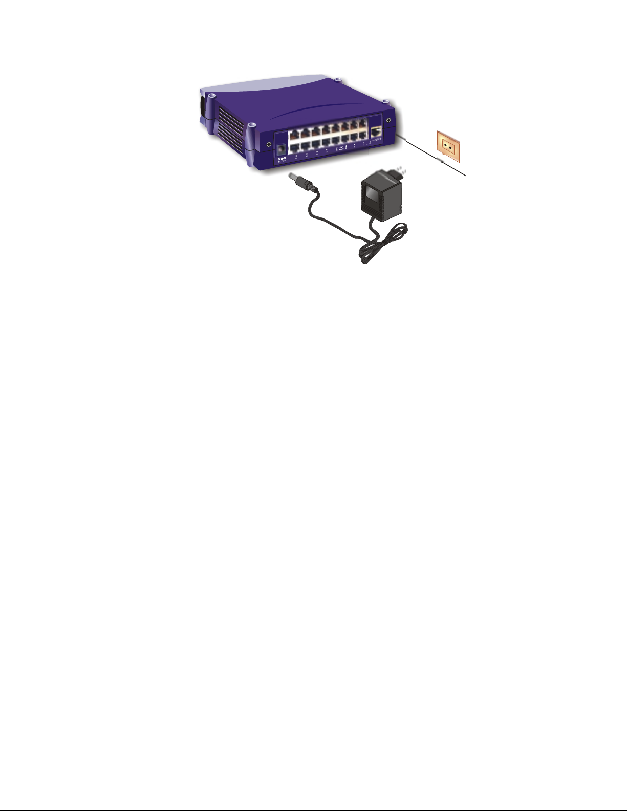
Fig. 3-6 Connecting the Switch to power outlet
20
Page 21

Expanding Your Network
Live-FSH16T Fast Ethernet Switch is primarily targeted not only as a concentrator to
converge workgroup traffic within Ethernet/Fast Ethernet; but also as a central switching
device to send incoming data to its destination LAN segment. With your existing
Ethernet/Fast Ethernet infrastructure, you can very easily connect, expand or migrate to
workgroup computing in an Ethernet/Fast Ethernet environment.
The following sections will introduce to you the basics of network connectivity in
workgroup computing within Ethernet/Fast Ethernet environment.
Connectivity Rules
10 Mbps Connection
Ethernet (10Mbps) network s should be configured according to the following connectivity
rules:
The maximum length for UTP cables m ust not ex ceed 100 meters from end s tation to a
shared-access 10BASE-T hub.
Between any two end stations in a collision domain, there may be up to five cable
segments and four intermediate repeaters at most.
If there is a path between any two end-stations containing five segments and four
repeaters, then at lea st tw o of th e cab le seg ments must be point-to-point link segments
(e.g. 10BASE-T, 10BASE-5), while the remaining segments may be of mixed
segments (e.g.: 10BASE-2 or 10BASE-5).
100 Mbps Connection
Fast Ethernet (100Mbps) network should be configured according to the following
connectivity rules:
The maximum length for UTP cables is 100 meters from end station and a
shared-access 100BASE-TX hub.
The maximum cabling length is 100 meters between end station and switch/repeater;
and 100 meters between switch and swi tch/re peater , thus m aking possible a maxim um
distance of 300 meters between two end stations.
21
Page 22

Hub-to-Switch connection
Live-FSH16T Fast Ethernet Switch allows a 10BASE-T or 100BASE-TX hub to be
connected to the Switch via a 4 –pair UTP / STP straight cable (Category 3, 4 or 5). Each
cable length can be up to 1 00 meters long (328 feet). Th e hub-to- switch connection is m ade
through the Uplink daisy -chain port (MDI II) on the hub to any of the s tation ports ( MDI-X)
on the Switch.
For a 10BASE-T or 100BASE-TX hub, the LED indicators on the Switch should give the
following signals to indicate a proper and
Link/Rx LED indicator should be ON
100 M LED indicator should be ON if connected to 100BASE-TX, otherwise it
should be OFF
Note: Both 10BASE-T and 100BASE-TX network environments allow uplinking, but each
follows different rules for connection.
Switch-to- switch Conne ction
Live-FSH16T Fast Ethernet Switch can be connected to another switch or other device
such as a router or bridg e by a two-pair U TP / STP St raight or Crossov er cable (Categ ory 3,
4, 5).
Using a Straight Cable
When using a straight cable, the switch-to-switch connection is done through the Uplink
daisy-chain port (MDI-II) of the Switch to any of the 10Mbps or 100Mbps station port
(MDI-X) of another switch or device.
functional connection:
Fig. 4-1 Connection through Uplink Port using straight-through cable
22
Page 23

Using a Crossover Cable
When connecting any 10/100 Mbps station port (MDI-X) of other switch or device with
any station port (MDI- X) of Live- FSH16T Fas t Etherne t Switch, it is requ ired th at you use
a crossover cable.
Fig. 4-2 Connection through Station Port using crossover cable
The LED indicators on L ive-FSH16T Fast Eth ernet Swi tch correspond ing to th e respect ive
connected port should give the following signals to indicate a proper and functional
connection:
Link/Rx indicators should be ON
100M LED is ON for a 100BASE-TX connection; otherwise it is OFF
FDX/Col LED status will depends on the status of th e other connected switch or dev ice
Note: Do not plug a phone jack connector into any RJ-45 port. This may damage the port.
Instead, use only twisted-pair cable with RJ-45 connector that conforms with FCC standards.
Note: Port 16 is shared w ith the Upli nk dais y-chain por t, alt hough their pi nouts ar e differen t. Do
not use both port 16 and the Uplink Port (MDI-II) at the same time.
Note: Make sure each twisted-pair cable does not exceed 100 meters. To connect to another
switch or hub, you may make a co nnection with station ports (MDI-X) at b oth ends if you use
crossover cable.
RJ-45 Port Description
RJ-45 station ports (MDI- X) can be attached t o any devices , which use a sta ndard network
interface (e.g., a workstation, server, bridge or router). But the Uplink daisy-chain port
(MDI-II) can be cascaded to a st ation port on simi lar networking devi ces (e.g. another
23
Page 24

switch or hub). When cascading multiple switches (or hubs), it is important that the UTP
cables should be of cro ssed - over type as s hown in th e diagram abov e. Also, m ake sure y ou
use the same pair of wire for pin pairs 1-2, 3-6,4-5 and 7-8.
Fig. 4-3 Pin assignments for crossover cabling
The wire schematics fo r bo th straig ht- through and cross ov er twisted- pair cables are shown
as below:
Fig. 4-4 Wire schematics for straight-through and crossover cable.
Summary
When connecting a computer to a switch, use a straight UTP cable.
When connecting Live-FSH16T to any station port (MD I- X ) of an other hub via its Uplink port
(MDI-II), use a straight-through UTP cable. Please note that the cabling distance is 100 meters
maximum.
When using crossover cable, the connection can be made from any station ports (MDI-X) of
Live-FSH16T to any station ports (MDI-X) of other devices.
Transmission Mode
All 10/100Mbps ports of Live-FSH16T Fast Ethernet Switch utilize auto-negotiation to
determine the transmission mode for any new connection. This means, if auto-negotiation
is supported on both ends of the connection, the Switch is initiated to negotiate for one of
the following transmission modes:
200Mbps/FDX
100Mbps/HDX
20Mbps/FDX
24
Page 25

10Mbps/HDX
Using Priority Ports
If you regularly use video/multimedia application on your LAN, you can maximize on the
Priority Queuing function the Liv e-FSH16T. Specific ally , the p riority ports a re port 5, 6, 7
and 8 and they are bu il t-in and without the nee d of any configuration. Us ing th ese priority
ports can ensure high priority traffic gets delivered efficiently, even when during bursts of
high traffic load. Traffic such as voice data and video (services which are streaming) are
prioritized, helping steady picture and sound quality.
To utilize prioritized traffic, just connect network devices that is dedicated to
voice/video/multimedia applications to a priority port (either port 5, 6, 7 or 8)
The priority level is set to High as compared to Normal (non-priority) level of the other
ports.
Applications
LAN Microsegmentation
In addition to workgroup performance improvement, Live-FSH16T Fast Ethernet Switch
can also effectively segment your network, significantly increasing both bandwidth and
throughput. Any port on the Switch can either be attached to a hub (i.e., shared collision
domain) or serve as a dedicated link to a si ngle ne twork device (e.g ., a work statio n). Whe n
a port on the Switch is connected to an Ethernet hub (i.e., a 10 or 100 Mbps repeater), the
bandwidth provided by that port i s shared by all the de vices connect ed to the at tac hed hub.
However, when a port is connected to an end node or to a device that breaks up the
collision domain (e.g., another Switch, bridge or router), the attached device has access to
the full bandwidth provided by that
port.
Microsegmentation of an existing LAN can improve network latency and increase overall
performance. Live-FSH16T Fast Ethernet Switch uses Store-and-Forward switching to
direct network traffic, thus ensuring data integrity under heavy load. Figure 4 -4 shows an
example of microsegmentation of the 10/100
BASE Fast Ethernet workgroup environm ent. Wi th su ch a v ersat il ity and flexi bi lity plus a
very cost-effective and easy installation, you will appreciate Live-FSH16T as your best
choice for migrating to workgroup computing. For details on the cabling requirements,
please refer to Chapter 3 and 4.
25
Page 26

Fig. 4-5 Microsegmentation in a LAN group
Easy Migration to Workgroup Computing
Live-FSH16T Fast Ethernet Switch serves primarily as a concentrator to converge your
workgroup traffic, and as a highly efficient switching device to forward the incoming data
to destination network segm ents. With its auto- sensi ng and nego tiating func tions, it m akes
your mixed Ethernet/Fast Ethernet networking environment as efficient and compatible.
Not only can you expand or upgrade to 100 Mbps bandwidth of Fast Ethernet without
virtually no effort, but also your existing Ethernet hardware inv estm ent are saved for your
leverage. It is a perfect solution to cater to your network expansion needs. With its Uplink
Port, Live-FSH16T is also extremely flexible in network configuration. Through
uplinking multiple switches, hubs or other devices, plenty of flexibility and expandability
is left for the network administrator to apply in future LAN configuration and expansion.
Whether you have just set u p your Ethernet /Fast Ethe rnet envir onment or y ou have already
got an existing Ethernet network, Live-FSH16T Fast Ethernet Switch is your best choice
for gaining the benefits and resources of workgroup computing. Since Live-FSH16T Fast
Ethernet Switch provides such a cost-effective way to gear up your network performance
toward workgroup computing, you will appreciate the easy plug-and-play function of its
installation within your network.
In fact, we can envision a w orkgroup env ironment as com plex as what is shown i n Fig. 4-5.
Often challenged with a he av y traffi c lo ad g enerat ed b y workg roup appl ica tions, y ou need
a device such as Liv e- FSH16T to a ct as a con centra tor and ce ntral swit ching d evice to tak e
care of the traffic flow. With its 16-port capacity, it can adopt as many end stations and
servers or even connect to other network devices. Through uplinking and cascading with
other devices, you can even expand this capacity in a very easy and cost-effective way.
26
Page 27

Fully compatible with either 10/100 Mbps connection in either half/full duplex
transmission mode, Live-FSH16T can easily connect devices with different transmission
speeds. With 100 Mbps providing
a much higher bandwidth than standard 10 Mbps Ethernet, you can rely on Live-FSH16T
to serve as an effective switching device to connect client computers to server or even a
server farm.
Priority Queuing
Live-FSH16T is equipped with the Pr iority Queuing function for port 5, 6, 7 and 8. Priority
port can ensure high priority traffic to be delivered efficiently, even when during bursts of
high traffic load. Traffic such as voice data and video (services which are streaming) are
thus prioritized, helping steady picture and sound quality.
If you have any plans to implement network telephony or any sort of video conferencing,
streaming video/audio or any real-time applications on your network you will need
Live-FSH16T for priority queuing. The benefit of priority queuing is that it can
dramatically improve the quality of priority services on the network. If priority queuing is
not implemented then the qual ity of these servic es will depend enti rely on the load on your
network. If network traffic is high, the service will not work properly.
27
Page 28
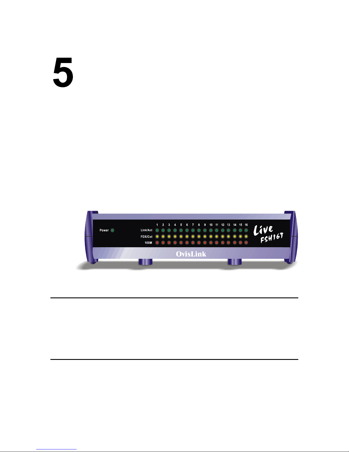
LED Indicators
The front-panel LED indicators enable users of Live-FSH16T Fast Ethernet Switch to
monitor the Power On/Off status of the Switch and the port status of each of its sixteen
10/100 Mbps station ports.
For the layout of LED indicators, please refer to Fig. 5-1 below.
As seen on Fig. 5-1, Power LED indicates the power on/off status of the switch. For each
station port, there are Link/Rx (Link/Activity), FDX/Col (Full-duplex/ Collision) and
100M LED to indicate its corre sponding port s tatus. You’l l find the LED indica tors to b e a
very convenient way for hub or port status monitoring and troubleshooting.
Before connecting any network device to Live-FSH16T Fast Ethernet Switch, you should
take a few minutes to look over this section and get familiar with the front panel LED
indicators of your Switch.
Power LED
Power LED will give a sol id green lig ht when you turn on the Switch, an d will be off when
the Switch being turned off. You can simply check the Power LED status to see if the
Switch is being act ivated or not. B efo re tur ning on the S witch, please v erify tha t the pow er
cord has been properly connected the Switch to the power outlet on the wall.
Station-port LEDs
Link/Rx LED
Link/Rx LED giving a solid green light indicates that a data link has been established
between the corresponding port and the device. If the connection is faulty, it will be off.
Fig. 5-1 LED indicators
28
Page 29

While the port is transmitting or receiving data, you will see a blinking green light.
If you’ve made a connection but the Link/Rx LED does not light up as expected, you
should check whether the R J-45 conn ectors are damag ed, or the cable type or pi n-out is not
correct, or the cable length exceeds the 100 meter limit.
FDX/Col LEDs
FDX/Col LED shows the transmission mode as well as the presence of collision on the
network.
When in full-duplex transmission mode, FDX/Col LED gives forth a solid yellow light.
When in half-duplex mode, it will be off. But, when in half-duplex mode, there are two or
more end stations on the same network segment attempting to transmit data at the same
time, a collision occurs. If there is a collision detected on specific network segment, the
corresponding FDX/Col LED shows a blinking yellow light. When a collision occurs, all
of the stations involved will recognize the collision, wait a random amount of time, and
retransmit.
FDX/Col LED status is summarized as follows:
ON : Transmission in full-duplex.
OFF: Transmission in half-duplex.
Blinking: Collision detected.
100 M LED
100M LED showing a solid red light indicates that the line speed going through that
specific 10/100 Mbps port is operating at 100Mbps mode. If the transmission speed
operates only at 10 Mbps, it is off.
A summary of the station-port LED status is listed in Table 5-1 below:
LED indicator Color Status Meaning
System LEDs
Power LED
Station Port LEDs
Link/Rx
FDX/Col
100M
● Green ON
OFF
● Green ON
Blinking
OFF
● Yellow ON
Blinking
OFF
● Red ON
OFF
Table 5-1: LED signals
Power ON
Power OFF
Connection is made
Transmitting/Receiving
No connection is made
Full Duplex
Collision (in half duplex)
Half Duplex
100Mbps speed
10Mbps speed
29
Page 30

Appendix A
Product Specifications
Standard Compliance
IEEE 802.3 10BASE-T Ethernet
IEEE 802.3u 100BASE-TX Fast Ethernet
IEEE 802.1p Class of Service (Priority queuing)
ANSI/IEEE Std 802.3 Nway auto-Negotiation
IEEE 802.3 Frame Type
Topology Star
Protocol CSMA/CD
Port Configuration
16 × 100 BASE-TX Ports
1 × Uplink Port
Priority Ports Port 5, 6, 7 and 8
Prioritization Sources Port-based Priority
Priority Level High/Normal
Data Rate
Ethernet
10 Megabit/sec (half-duplex)
20 Megabit/sec (full-duplex)
Fast Ethernet
100 Megabit/sec (half-duplex)
200 Megabit/sec (full-duplex)
Transmission method Store and Forward
Full Duplex Auto-negotiation
RAM Buffer 512 Kbytes per device
Active Flow Control IEEE 802.3x compliant flow control for full duplex
Back Pressure option for half duplex
Filtering Address Table 16 K per device
Packet Filtering/Forwarding rate Wire speed for 10/100 Mbps
30
Page 31

MAC Address Learning Automatic update
Cabling Type
100BASE-TX
4-pair 100 ohm Category 5 UTP or STP (100 m) cable
10BASE-T
4-pair 100 ohm Category 3,4,5 UTP(100 m) cable
Cabling distance 100 meters for switch-to-repeater connection
100 meters for switch-to-station
LED layout
System Status LEDs
Power LED
Station port LEDs
Link/Rx LEDs
FDX/Col LEDs
100 M LEDs
Dimensions 209 × 144 × 49 m/m
Net Weight 600 g
Power Input External Power Supply with + 7.5 V
@ 2A output
DC
Power Consumption 45 Watts max, @ 100 ~ 240 V AC
Operating Temperature 32 ~ 122
°F / 0 ~ 50 °C
Storage Temperature - 40 ~ 149
°F / -40 ~ 65 °C
Humidity < 95% (non-condensing)
Safety / EMI Certificates FCC Class A, CE mark
31
Page 32

Appendix B
Troubleshooting
This appendix contains information to help you identify and solve problems. If your switch does
not function properly, please make sure it is set up according to the instructions on the manual.
If you suspect your switch is not connected correctly to your network, check the following points
before you contact your local dealer for support.
Make sure that the maximum cable length between sw itch and end node does not exceed 100 m
Make sure that the maximum switch-to-repeater cable distance does not exceed 100 meters
Verify that the cabling type used is correct (Category 5 UTP)
Check the Link/Rx LED lights on the front panel to see if it lig hts up. If it does not l ight up, that
means a faulty connec tion. Check the status of the cabl e attachm ent. If the p roblem persists, try
a different cable.
Try another port on the Switch.
Turn off power supply to the Switch. After a while, turn it on again to see if it resumes to its
normal function.
If you find out where the problem is but can not solve it by yourself, or you simply cannot locate
what is at fault, please contact your local dealer for technical support.
32
 Loading...