

Page 1
Page 2

Page 3

16 & 24 Ports RJ-45 10/100 Mbps Web-Management Switch
USER´S MANUAL:
OvisLink Corporation, thank you the loyalty you have shown in our company, for
sure the performance and the
quality of our devices will satify your demands.
PACKAGING CONTENTS:
Before proceed with the installation procedure, please make sure you have received all the next elements:
- 1 FSH16W or FSH24W Fast Ethernet Switch.
- 2 Supporting frame
- 4 rubber padding
- This user’s manual
- 1 power cable
If any element is remaining, please contact with your distributor.
QUICK INSTALLATION GUIDE:
Location of the Switch.
Choose a proper place such as desk platform for the rack mountable switch, considering the surrounding such as
power requirements, space, keep it away from sunlight, heat source, and electromagnetism interference
area. The wind range must be at least 10 cm for a good ventilation.
Installation & Connection method:
1. Stick the rubber padding to the rear side of the switch.
2. Use standard EIA19’ rack mount and fix the EL rack on both sides of the switch.
3. Adjust the holes so that they can fit and fasten the switch with the turnbuckle.
4. Plug the cable into the switch socket, turn the power on, the switch will test itself, all indicators and lights are on
at the same time, after 2 seconds the lights automatically turn off and test is done.
5. Put one end of the cable into a RJ45 port of the switch, the other end is connected with the NIC card and
router. Cat. 3,4.5 cables can be used, Cat. 5 is recommendable. If the power of the switch is on, the related
indicators are on. Every port of the switch can be used as Uplink port.
Note: Don’t plug the phone line into RJ45 port, otherwise it will damage the unit.
6. The switch can adjust the power automatically depending on the input voltage within the marked voltage on the
rearboard.
LED INDICATORS:
LED Estado Indications
POWER ON/OFF Power on/ off
LINK ON/OFF Ports connected / Ports unconnected
FLASH Data frames are through
SPD.
ON/OFF The transmission rate among ports is 100Mbps.the
transmision rate is 10Mbps.
ENGLISH
1
Page 4
Computer setup:
Configure the IP adress of the computer with 192.168.2.2. To do it, please, follow the following steps.
1. If you use Windows 2000/XP, open the Configuration Panel and then the Network Connections.
2. Right click on the Local Network Connection and choose Properties.
3. Click twice on Internet Protocol TCP/IP.
4. Select Specify an IP Address :
- IP Address : 192.168.2.2
- Subnet Mask : 255.255.255.0
7. Click on OK.
8. Click on Close.
Login Window :
1. The default IP address of the FSH16W or FSH24W is 192.168.2.1. Please, open your favorite web browser
and tape :
http://192.168.2.1
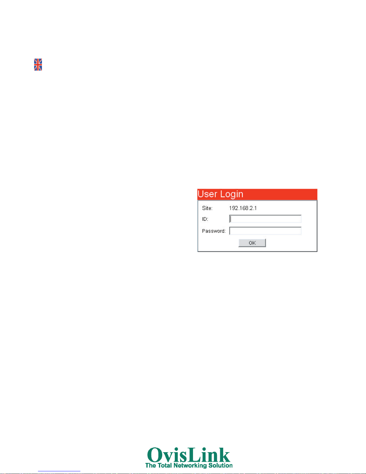
2. The login windows will appear. The ID is admin, and the
Password is system. Enter them in the login windows and
click on
OK.
3. The website allow you to configure the following features :
- Administrator :
That allows you to configure the authentication (login) and
the IP address of the switch, to see the status
and to do
a Reset and a Firmware update.
- Port Management :
That allows you to configure each port (Speed, FDX, Bandwith...), to specify a Port Mirroring and to enable the
Broadcast Storm Control feature.
- VLAN Setting :
That allows you to separate the physical network (the switch) in several logicals subnet (each port or a port
group). It’s a way to secure the
LAN communication defining VLAN groups. Each port in a group can
communicate with the others. But, each group can’t communicate with the others. Some shared resources can
be define to give to each VLAN group an internet access or an access to a network printer, server, ...
- Trunk Setting :
That allows you to configure an high-speed communication link between two switches. In fact, this feature use
until 4 ports to create an “highway” to another
switch. So, you can obtain a bandwith until 400/800 Mbps
(Half/Full-Duplex).
- QoS Setting :
That allows to configure the Priority and the Class of Service to improve the datas transfert.
- MAC Address :
That allows to configure the MAC table. So, you can control the LAN communication into the switch. For
example, you can forbid to a computer to communicate on your LAN by disabling the MAC Address Learning
fonction of the switch.
2
ENGLISH
Page 5
TROUBLESHOOTING:
After cables are connected, the LED indicator does not work.
1. Check if the connection ports work normally.
2. Check if the cable is properly connected. If the link light ( green light in NIC card) is on , it shows everything is
normal.
3. Check if the cables are the right type and net card/cables are ok.
Power and cooling system don’t work.
1. Check if the plug is loose or power is normal or voltage is stable.
2. Check if the fan in the case is in normal.
SPECIFICATIONS:
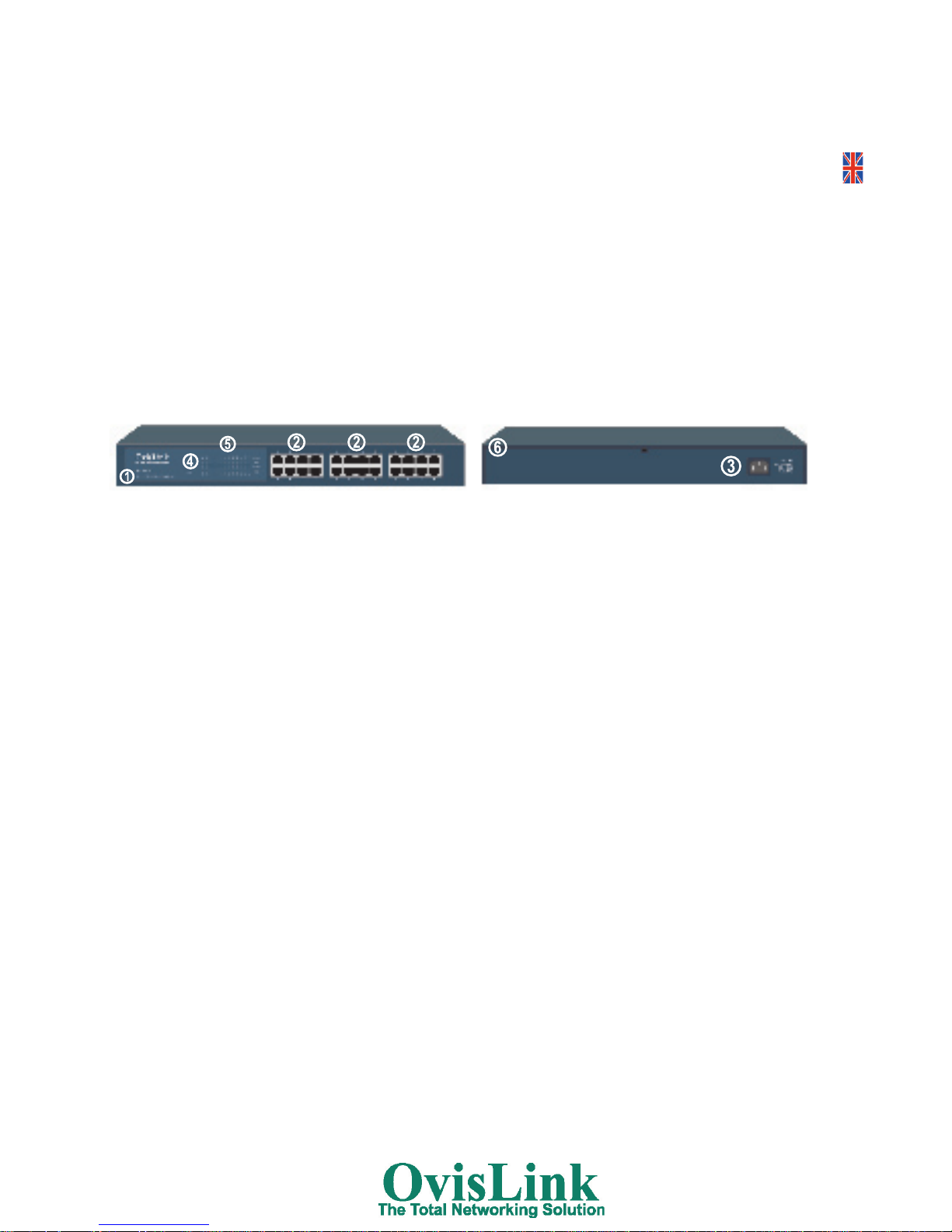
Physical description
front Panel. Rear Panel
1. Model Number. 4. Power Indicator.
2. 1-24 RJ45 Ports. 5. Port Indicator.
3. Power Plug. 6. Fan.
• Standards:
- IEEE 802.3 10BASE-T Ethernet,
- IEEE802.3x 100BASE-T Ethernet
- ANSI/IEEE standard 802.3 N-Way auto-negotiation
• Protocol: CSMA/CD.
• Max Forwarding Rate and Max Filtering Rate: 14,880 pps Ethernet port,148,800 pps per Fast Ethernet port
• Network Cables:
- 10Base-T: 2-pair UTP/STP Cat. 3, 4, 5 cable EIA/TIA-568 (100m)
- 100Base-TX: 2-pair UTP/STP Cat. 5 cable EIA / TIA-568 (100m)
• Dimensions: 440mm x 225mm x 44mm (L x W x H)
• Temperature:
- Working
: 0 C to 50 C (32 F to 113 F),
- Storage temperature: -200C~1250C
• Working Humidity: 10% to 90% (Non-condensing)
• Max power consumption: 25W
• Power Supply:
- Input rate: 100~250V AC, 50~60Hz
- Internal universal power supply: 3.3V/3A, 5V/1A
• EMI: FCC Class A, CE Mark.
ENGLISH
3
Page 6

DECLARATION OF CONFORMITY:
Hereby, OvisLink Corporation declares that thess FSH16W and FSH24W are in compliance with the
essential requirements and other provision of Directive 1999/5/EC
The following importer/manufacturer is responsible for this declaration of conformity:
Company Name: OvisLink France SA
Adress: 16-18 Route de ROUEN, 27950 SAINT-MARCEL. France.
Tel.:
+33 (0) 2 32 71 15 09
Fax: +33 (0) 2 32 54 87 28
Name: Horia SCURTU
Position: General Manager.
Date: 25/06/2004.
Signature:
GUARANTEE CONDITIONS FOR UNITED KINGDOM AND IRELAND.
This product has passed successfully strict quality tests that guarantee this product is in perfect
working condition; free of manufacture defects enabling best performance.
This product has a Life Time Guarantee, in the event that any fault or defect is discovered, we will,
unless the fault or defect has been caused by a misuse of the goods or manipulation by nonqualified person or because of future incompatibilities or by the product being used for a purpose
for which it was not been designed, either repair or, at our option, it will be replaced by other
similar or better, new or repaired product free of charge to the purchaser.
Contact with your local distributor for further information respect change procedure.
For further information, please contact with:
United Kingdom and Ireland.
Web.: www.ovistel.co.uk
Tel.: +44 1256 398597
ENGLISH
4
Page 7

Switch 16 & 24 Ports RJ-45 10/100 Mbps Web-Management
MANUEL DE L’UTILISATEUR:
La société OvisLink vous remercie de votre confiance pour l’acquisition de ce
produit. Soyez sûr que la
performance et la qualité de nos produits satisferont vos besoins.
CONTENU DE LA BOITE:
Avant de procéder à l’installation du produit, veuillez vérifier que tous les éléments sont présents dans la boîte. Si
ce n’est pas le cas, veuillez prendre contact avec votre revendeur :
- Switch FSH16W ou FSH24W
- Système de fixation dans une armoire 19’’
- 4 gommes autollantes
- Câble d’alimentation
- Manuel
GUIDE D’INSTALLATION RAPIDE:
Mise en place du switch.
Choisissez un emplacement propre, sec et ventilé. Ce switch étant rackable, vous pouvez le monter dans une baie
de brassage (fixations fournies) ou bien le déposer sur une surface de préférence plate et horizontale (gommes
fournies). Evitez d’installer le produit près d’une source lumineuse, de chaleur, ou d’interférences magnétiques.
Laissez un espace de ventilation d’environ 10 cm autour du produit.
Installation et connexion:
1. Collez les gommes anti-dérapantes sous le switch.
2. Installez les ailettes de fixation pour le montage dans la baie de brassage de 19’’.
3. Vissez le switch dans la baie.
4. Branchez le câble d’alimentation dans le connecteur approprié pour que le switch puisse se mettre en route.
Les voyants vont s’allumer puis s’éteindront 2 secondes après
5. Reliez une extrémité du câble RJ-45 sur l’un des connecteurs du switch, et l’autre extrémité à une carte réseau,
un routeur ou une imprimante. Suivant la vitesse, des câbles de catégorie 3, 4 ou 5 peuvent être utilisés. Nous
vous recommandons tout de même de n’utiliser que du Catégorie 5. Si le switch est sous tension, les voyants
du port devraient s’allumer. Ce switch accepte aussi bien les câbles droits que les câbles croisé et ce, sur tous
les ports.
Note: Ne connectez pas de ligne téléphonique sur les ports RJ-45 sous risque d’endommager le switch et de
faire sauter la garantie.
6. L’alimentation du switch s’adapte automatiquement selon le pays où vous vous trouvez.
7. Veuillez vous assurez que les câbles sont correctement sertis d’après la norme 568A/B et que la distance ne
dépasse pas 100 mètres.
INDICATEURS LED:
LED Etat Significations
POWER ON/OFF Allumé / Eteint
LINK ON/OFF Ports connectés / Ports déconnectés
CLIGNOTANT Transfert en cours
SPD.
ON/OFF Connexion en 100 Mbps / Connexion en 10 Mbps
FRANÇAIS
5
Page 8

FRANÇAIS
Configuration de l’ordinateur:
Veuillez configurer l’adresse IP de l’ordinateur en 192.168.2.2 grâce aux étapes suivantes.
1. Si vous utilisez Windows 2000/XP, ouvrez le Panneau de Configuration et les Connexions Réseau.
2. Faîtes un clic droit sur votre Connexion Réseau Local et cliquez sur Propriétés.
3. Double cliquez sur Protocole Internet TCP/IP.
4. Sélectionnez Spécifier une adresse IP :
- Adresse IP : 192.168.2.2
- Masque sous-réseau :
255.255.255.0
7. Cliquez sur OK.
8. Cliquez sur Fermer.
Fenêtre de Login :
1. L’adresse IP par défaut des switches FSH16W et FSH24W est 192.168.2.1. Veuillez ouvrir votre navigateur
préféré et tapez :
http://192.168.2.1
2. La fenêtre de login apparaîtra. l’ID est admin, et le
Password est system. Entrez les dans les champs et
cliquez sur
OK.
3. Voici ce que permet de configurer le site internet :
- Administrator :
Cela vous permet de configurer l’authentification (login) et
l’adresse IP du switch, de voir le statut et d’effectuer un
Reset et une Mise à jour du Firmware.
- Port Management :
Cela vous permet de configurer chaque port (Speed, FDX, Bandwith...), de spécifier un Port Mirroring et
d’activer la fonction Broadcast Storm Control.
- VLAN Setting :
Cela vous permet de séparer le réseau physique (le switch) en plusieurs sous-réseaux logiques (chaque port
ou
groupe de ports). C’est un moyen de sécuriser les communications de votre LAN en définissant des groupes
VLAN.
Chaque port d’un groupe peut communiquer avec les autres. En revanche, chaque groupe ne peut
pas communiquer avec les autres. Des ressources partagées peuvent être définies pour donner à chaque
groupe VLAN, une connexion internet ou un accès à une imprimante réseau, un serveur, ...
- Trunk Setting :
Cela vous permet de configurer un lien de communication à très haut débit entre deux switches. En fait, cette
fonction utilise
un système d’aggrégation des liens jusqu’à 4 ports pour communiquer vers un autre switch.
Donc, vous pouvez obtenir une bande passante jusqu’à 400/800 Mbps (Half/Full-Duplex).
- QoS Setting :
Cela vous permet de configurer les Priorités et le Class of Service pour améliorer le transfert des données.
- MAC Address :
Cela vous permet de configurer la table d’adresses MAC. Donc, vous pouvez contrôler les communications
locales dans le switch. Par exemple, vous pouvez interdire à un ordinateur de communiquer sur votre réseau
en désactivant la fonction d’apprentissage des adresses MAC du switch.
6
Page 9

DÉPANNAGE:
Après avoir connecté les câbles, les LED ne s’allument pas
1. Vérifier que les câbles sont correctement branchés de part et d’autr
2. Vérifier que les LED du produit réseau connecté au switch soient bien allumées.
3. Si le câble ne fait pas plus de 100 m, les LED du switch devraient s’allumer
4. Si ce n’est pas le cas, vérifier que le câble répond bien aux normes Catégorie 5 et pour le câblage, 568A/B
5. Si elles ne s’allument toujours pas, contactez votre revendeur.
SPÉCIFICATIONS:
1. Référence du modèle 4. Voyant POWER
2. 24 ports RJ-45 10/100 Mbps 5. Panneau de contrôle par LED
3. Connecteur d’alimentation 3. Ventilateur.
• Standards:
- IEEE802.3u 10Base-T
- IEEE802.3x 100Base-Tx
- ANSI/IEEE 802.3 N-way auto-négociation.
• Protocole: CSMA/CD.
• Taux de filtrage:
- 14880 pps (10 Mbps) max.
- 148800 pps (100 Mbps) max.
• Mémoire: 4 Mbits de mémoire tampon.
• Fond de panier: 4.8 Gbps permettant au switch de ne pas saturé.
• Panneau de LED: 1x Power et par port :
- 10/100M
- LINK/ACT
- SPD
• Câble:
- 10 Mbps : Catégorie 3, 4 ou 5 UTP/STP jusque 100 mètres
- 100 Mbps : Catégorie 5 UTP/STP jusque 100 mètres
• Dimensions: 440 x 225 x 44 mm (L x l x H)
• Température:
- En fonctionnement : De 0º a 50ºC
- En stockage : -20 à 125 °C
• Humidité: 10 à 90% (non condensée).
• Consommation: 25W
• Alimentation: 100~250V AC, 50~60Hz. Alimentation interne universelle 3.3V/13A, 5V/1A.
• EMI: FCC Class A, CE Mark
FRANÇAIS
7
Page 10

DÉCLARATION DE CONFORMITÉ:
Par la présente, OvisLink France SA déclare que les FSH16W et FSH24W sont conformes avec les
caractéristiques essentielles de la directive 1999/5/EC.
L’importateur/fabricant suivant est responsable de cette déclaration de conformité:
Nom de la société: OvisLink France SA
Direction: 16-18 Route de ROUEN, 27950 SAINT-MARCEL. France.
Tel.:
02 32 71 15 09
Fax: 02 32 54 87 28
Nom: Horia SCURTU
Position: Gérant.
Date: 25/06/2004
Signature:
CONDITIONS DE GARANTIE POUR LA FRANCE.
Ce produit a passé les rigoureux contrôles de qualité, qui garantissent que le matériel fonctionne
correctement, sans défauts de fabrication et qui permettra d’obtenir des performances élevées.
Ce produit est garanti à vie et dans le cas où vous rencontreriez un quelconque défaut de
fabrication ou de fonctionnement, il vous sera échanger contre un produit fonctionnel, neuf ou
réparé, équivalent ou supérieur en caractéristiques. Pour connaître la procédure d’échange, prenez
contact avec votre revendeur.
La présente Garantie ne peut s’appliquer lors d’un dégât normal, de dégâts dûs à une mauvaise
utilisation ou manipulation par une personne non qualifiée ou de l’évolution de produits tiers
entraînant une incompatibilité. OvisLink ne sera pas responsable des dommages causés sur ce
produit par un usage incorrecte.
Pour plus d’informations, prenez contact avec OvisLink :
France.
e-mail:
support@ovislink.fr
Web: www.ovislink.fr
Hotline: 0 891 700 704
FRANÇAIS
8
Page 11

16 & 24 Ports RJ-45 10/100 Mbps Switch Administración
Web
MANUAL DE USUARIO:
OvisLink Corporación España, le agradece la confianza depositada en sus productos, seguro que tanto las
prestaciones como la calidad del dispositivo que acaba de comprar no le defraudará.
CONTENIDO DEL PAQUETE
:
Antes de proceder a la instalación del dispositivo, por favor asegúrese que en su caja, se encuentran los siguientes elementos:
- 1 Switch de 24 puertos EVO-FSH24.
- 2 soportes para instalación en Rack 19”.
- 4 soportes de goma antideslizante.
- Cable de alimentación.
- Este manual de usuario.
GUÍA RÁPIDA DE INSTALACIÓN:
Emplazamiento del Switch.
Elija preferiblemente una superficie lisa y horizontal donde instalar el switch, teniendo en cuenta las necesidades
de alimentación y espacio necesario. Evite la luz solar directa, fuentes de calor y areas de fuertes interferencias
electromagnéticas. Para una buena ventilación, se recomienda un espacio libre de 10 cm. en la parte del
ventilador.
Instalación:
1. Pegue los soportes de goma en el switch.
2. Utilice ambos soportes metálicos (uno a cada lado), para la instalación en rack 19”.
3. Conecte el cable de alimentación y encienda el switch. En ese momento al switch se le encenderán todas las
luces, indicando que se está realizando un test. Pasados unos 2 segundos las luces se apagarán indicando la
finalización del test.
4. Introduzca un extremo del cable UTP en un puerto RJ45 del switch y el otro extremo en la tarjeta de red del
equipo o router. Se pueden utilizar cables UTO Cat.3, 4 y 5, aunque se recomienda Cat. 5. Todos los puertos
pueden utilizarse como Up-Link.
Nota: No conecte directamente al switch la línea de teléfono (RJ45), ya que se podría dañar el dispositivo.
5. El switch ajusta automáticamente el voltaje de entrada, dentro de los límites marcados en la parte trasera.
6. Asegúrese que los cables están firmemente conectados y que la longitud máxima de los cables no supera los
100 m.
Indicadores LED:
LED Estado Significado
POWER ON/OFF Switch encendido/apagado
LINK ON/OFF Puertos conectados/desconectados
INTERMITENTE Transmitiendo datos
SPD.
ON/OFF Transmisión a 100 Mbps./10 Mbps.
ESPAÑOL
9
Page 12

Configuración del equipo :
Configure la dirección IP de su equipo con 192.168.2.2 Para hacerlo siga los siguiente pasos :
1. Si está usando Windows 2000/XP, abra el Panel de Control
y vaya a Conexiones de Red.
2. Haga click con el boton derecho del ratón en Conexión de Área Local y seleccione Propiedades.
3. Haga doble click en Protocolo de Internet (TCP/IP).
4. Seleccione Especificar una dirección IP :
- Dirección IP : 192.168.2.2
- Mascara de Subred : 255.255.255.0
5. Haga click en Aceptar en todas las pantallas
Pantalla de conexión :
1. La dirección IP para el FSH16W o el FSH24W es
192.168.2.1. Abra su navegador e introduzca
http://192.168.2.1
2. Le aparecerá una ventana de conexión solicitandole
usuario y contraseña. Introduzca los valores :
- ID : admin
- Password : system
3. La interfaz Web permite configurar las siguientes opciones:
ADMINISTRATOR :
Permite configurar la autentificación de entrada
(ID/Password), la dirección IP del switch, ver el estado,
Aplicar o Resetear y actualizar el Firmware.
PORT MANAGEMENT :
Permite configurar en cada puerto (Velocidad, FDX, Ancho de Banda...), especificar un Puerto Espejo y habilitar la
capacidad de Control de Tormente de Broadcast.
VLAN SETTING :
Esta opción permite separar una red física (switch) en redes lógicas (cada puerto o grupo de puertos). La manera
de asegurar las comunicaciones LAN definiendo grupos de VLAN. Cada puerto dentro del grupo se puede comunicar con los otros. Pero cada grupo no se puede comunicar con los otros. Algunos recursos compartidos pueden
estar definidos para cada grupo VLAN (grupo para acceder a Internet o acceder a una red, servidores, ...
TRUNKING SETTING :
Esto permite configurar una velocidad alta de comunicación entre dos switches. Se puede usar esta opción para
establecer una conexión de banda ancha hacia otro switch. Asique puede conseguir una conexión de 400/800
Mbps (Half/Full-Duplex).
QoS SETTING :
Esto permite configurar los Priority y Class of Service para mejorar la transferencia de los datos.
MAC ADDRESS :
Esto permite configurar la tabla MAC. Por ejemplo, puede prohibir a un equipo comunicarse en la LAN deshabili
-
tando la función de aprendizaje de direcciones MAC (MAC address Learning), en el switch.
10
ESPAÑOL
Page 13

SOLUCIÓN DE PROBLEMAS:
Después de conectar los cables, los LED no funcionan correctamente.
1. Chequee si la conexión de los puertos es correcta.
2. Compruebe si el cable está conectado correctamente. Si el LED de la tarjeta (normalmente verde) está
encendido, significa que todo está normal.
3. Chequee si el tipo de los cables es el correcto, si el grimpaje es adecuado y las tarjetas de red se encuentran
en buen estado de funcionamiento.
La ventilación y/o alimentación no funcionan.
1. Compruebe el cable de alimentación, si hay corriente en el enchufe y si el voltaje es estable.
2. Chequee si el ventilador se encuentra en buen estado.
CARACTERÍSTICAS TÉCNICAS:
Descripción física
Parte frontal. Parte trasera
1. Modelo 4. Indicador de alimentación
2. Puertos 5. Indicador de puertos
3. Conexión a la corriente 6. Ventilador
• Estándares:
- IEEE 802.3 10Base-T y IEEE 802.3u 100Base-T
- ANSI/IEEE N-Way autonegociación.
- IEEE 802.3x Flow Control en Full-Duplex y Back Pressure en Half-Duplex.
• Protocolo: CSMA/CD.
• Puertos: 24 puertos RJ45 10/100 Mbps. Auto MDI/MDI-X
• Método de transmisión: Store and Forward.
• Indicadores LED:
-
2 por puerto: 10/100 Mbps (SPD) y Link/ACT.
-
1 de alimentación.
• Dimensiones: 440 x 225 x 44 mm.
• Temperatura:
- En funcionamiento:
De 0º a 50ºC
- En almacén:
De -20º a 125ºC
• Humedad: De 10% a 90% (sin condensación)
• Consumo máximo: 25W
• Alimentación: 100-250V AC, 50-60Hz. Fuente de alimentación interna 3.3V/13A, 5V/1A.
• Certificaciones: CE y FCC.
ESPAÑOL
11
Page 14

ESPAÑOL
DECLARACIÓN DE CONFORMIDAD:
Por medio de la presente, OvisLink declara que los Switches FSH16W y FSH24W cumplen los requisitos
esenciales de la Directiva 99/05/CE.
El siguiente fabricante/importador es responsable de esta declaración:
Nombre de la compañía: OvisLink France SA
Domicilio: 16-18 Route de ROUEN, 27950 SAINT-MARCEL. France.
Teléfono:
+33 (0) 2 32 71 15 09
Fax: +33 (0) 2 32 54 87 28
Nombre: Horia SCURTU
Cargo: Director General.
Fecha: 25/06/2004
Firma:
GARANTÍA. CONDICIONES DE GARANTÍA EN ESPAÑA Y LATINOAMÉRICA
Este producto ha pasado satisfactoriamente rigurosos controles de calidad, que garantizan que este
dispositivo se encuentra en perfectas condiciones, libre de defectos de fabricación y del que podrá
obtener las máximas prestaciones.
Este producto está garantizado de por vida, por lo que en caso de encontrar algún defecto de
fabricación o avería, se le repondrá por un producto en funcionamiento, nuevo o reparado,
equivalente o superior en características. Para conocer el procedimiento de la sustitución en
garantía, póngase en contacto con su proveedor.
La presente Garantía no será aplicable por causas derivadas de un desgaste normal, ni a los
daños que puedan ocasionarse por uso indebido, inadecuado, por falta de cuidado o accidente,
manipulación por personal no cualificado, ni por futuras apariciones de incompatibilidades
con terceros productos. OvisLink no se hará responsable de los daños derivados directa o
indirectamente de un posible fallo del producto por causas de un uso indebido.
Para más información, póngase en contacto con las siguientes sucursales:
España.
Tel.:
902 152 608.
e-mail:
garantias@ovislinkcorp.es
Web:
www.ovislinkcorp.es
Latinoamérica. Chile.
Tel.:
56+2+2642980
e-mail:
servicio@ovislinkcorp.cl
Web:
www.ovislinkcorp.cl
12
Page 15

Page 16

 Loading...