

Page 1
Wireless NVR User Guide
Wireless NVR User Guide
Introduction
1 Statement
Thank you purchasing our products, if you have any questions or
needs, please contact us.
This manual applies to wirel es s network video recorder.
The company based on product feature enhancements and updates the
contents of this manual, and will be regularly updated or improved
products or processes that are described in this manual. Updates will be
added to the new version of this manual without prior notice.
If the description of the manual doesn't match for the material object
,prevail in kind.
2 Attentions
Please double check when unpacking boxes, confirm the items and
lists.
Please don’t make the kit fall to ground or be hit by strong forces.
Please keep good ventil ation environment around this product.
Avoid installation in severe vibration environments.
Please avoid environment with much humidity, dust, extreme heat or
extreme cold of the power supply carefully.
Please avoid environment with much humidity, dust, extreme heat or
extreme cold of the power supply carefully.
Please keep the pro duct box to facilitate transfer or removal o f the
equipment.
Please make sure to turn off power of all items during installation.
Check the voltage properly.
Please contact th e di stributor or service center i f the kit is damaged or
not working
3 Open-package inspection
After receive product, please open giftbox then check accessories. If any
damage or lack,kindly please contact to the distributor.
Packing list
S/N Item Quantity
1 NVR Host 1
2 Screw bag(4 screws for HDD) 4
3 USB Mouse 1
4
1 meter network cable(for IPC code match)
1
5
DC 12V@3A Power supply (NVR)
1
6
Product user manuals
1
7
Wireless IP Camera
4/9
8
DC 12V@1A Power supply (for IPC)
4/9
9
Screw bag(4 screws for HDD)
4/9
4 Product description
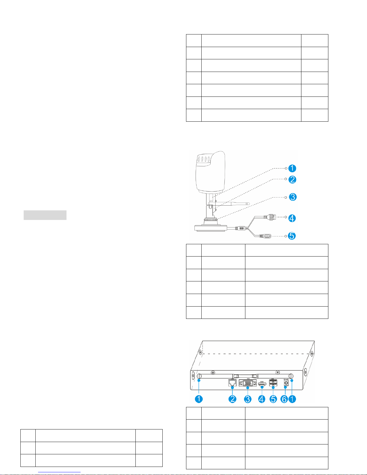
4.1 Wireless Camera
S/N Item Description
1 Antenna interface Install antenna
2 Setscrew Fi xed bracket
3 Knob Adjust the camera angle
4
Network interface
Connector for LAN
5
Power Supply
12VDC power supply.
4.2 Wireless NVR
S/N Item Description
1 Antenna interface Install antenna
2 Network interface Connector for LAN
3 VGA interface DB9 connector for VGA output
4
HDMI interface
HDMI video output connector
Page 2
Wireless NVR User Guide
5
USB interface
USB ports for additional devices
such as USB mouse, U disk
6
Power Supply
12VDC power supply.
5 Installation device
5.1 Install wireless camera
Note: 1.Disconnect the power from the NVR before installing a hard disk
drive (HDD). A factory recommended HDD should be used for this
installation.
2. The maximum of hard disk capacity supported is 4TB.
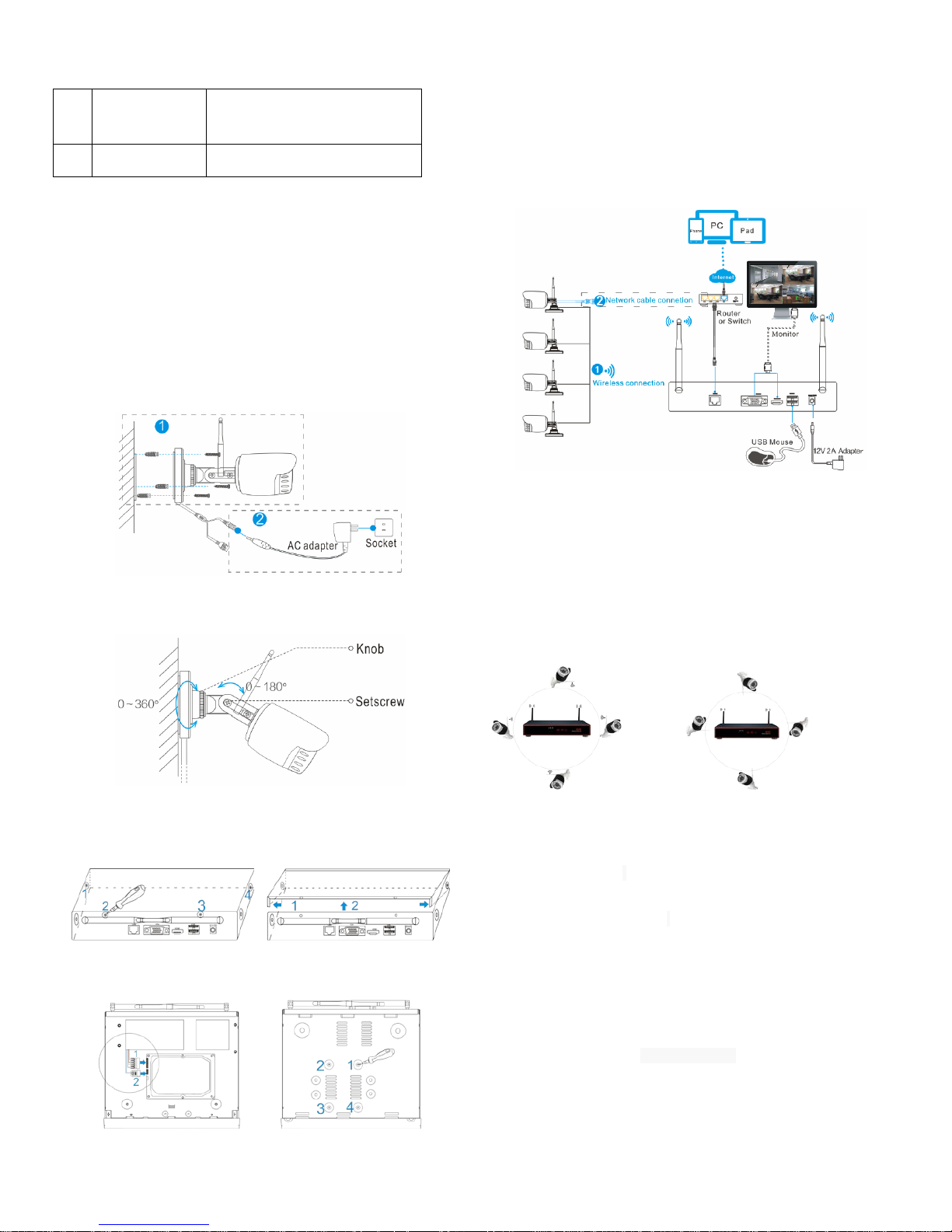
Setps:
(1) Drill mounting holes, push in screws and fasten the screws.
(2) Connet Power adapter to socket
(3) Loosen the setscrew and knob,adju s t the camera angle according to
your surveillance need,then fasten the screws.
5.2 Install wireless NVR
Setps:
1. Install the hard disk with a cross screwdriver
(1) Unfastening the screws on the rear panel,and side panel.
(2) Remove the cover from the NVR
(3) Connect the data cable and power cable to HDD
(4) Fasten the screws on the bottom to fix the HDD.
(5) Re-install the cover of the NVR and fasten screws.
2. Cable Connection
(1) Connect mouse to USB inter f ace ;
(2) Connect to monitor by HDMI cable or VGA cable;
(3) Connect to internet by netw ork cable via router(or switch);
(4) Connect to 12VDC adapter and turn on power,the Power indicator
would turn red.
Notes:
1.Please connect the wireless camera and NVR with network cab le, if
many obstructions between them, the distance is too far or other factors
cause the wireless signal is we ak and the image is not normal.
2. . In order to guarantee the video quality, IPC antenna should try to keep
in parallel or tangent with NVR antenna.Because the signal of surrounding
antenna is much stronger ,but much weaker if antenna endpoints back off
direction.
Correct method Fault method
6 Local Operation
Necessary Operation: NVR can only be recording and remote
access,after perform necessary operations.
Optional Operation:You can de decide whether to do this as you
like,such as video playback,backup, device operation , et c.
6.1 Necessary Operation
Step 1: Startup
Check the power supply is plugged into an electrical outlet,and turn
on the button.Then the power LED should red,and the video will automatic
display on the monitor,after several minutes.
Page 3
Wireless NVR User Guide
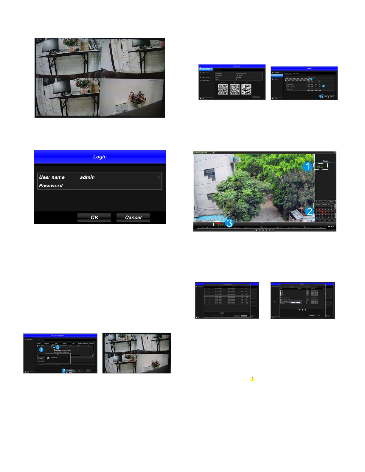
Step 2: Login
(1)click right mouse button, log-in menu pops up.
(2)Enter the correct password, default password is blank.
Note: Please modify the user password before using the product to protect
your privacy.
Password modificat i on: " Main menu → The system menu → User
configuration →Edit button → Edit the u menu → Enter the original
password: (blank) →Check password → Set a new password → OK "to
change passwords.
Step 3: Format the hard disk
Only NVR can record after format hard disk.
(1) Right click to login and enter “Main menu→HD manager”;
(2) Select the hard disk,and clik “Initalize” button ;
(3) The hard disk status would turn on “work”.It’ll display”REC” on
each live view channel,and start record.
(1) HD manager (2) display “REC”on live view
Step 4: Network configuration
You can remote access NVR via phone or internet after configure network
parameter successful.
(1) Conform network cable is connected to LAN correctly for access the
internet;
(2) If the P2P status is “on”,the network configura t ion i s ok. Otherwise
please perform the following steps;
(3) Enter into”Main menu→System→Network” menu;
(4) Select”DHCP”,and click “save” button,it”ll request IP address from
the DHCP server automatically;
(5) ,the configuration is ok,if the IP address is not 192.168.1.2,After
refresh. Otherwise,please set the IP address and gat eway information
Manually.
(1) P2P status (2) Network configuration
6.2 Optional Operation
(1) video playback
Steps:Right click to select playback→login→select channel→select date
→double click to start play record
(2) video backup
Steps:Insert U di sk t o USB interface→Right click to select Main menu→
login→select backup→select chan nel→set starting time and ending time→
click “Search”button→select the record→select or create new file→click
“Backup”button to backup record.
(1) record list (2) backup record
(3) Add camera
Add or replace wireless camera,please fellow the steps below.
a) Connect camera to NVR by network cable,and wait 1.5minutes for
camera startup.
b) Enter ”Main menu→ channel management” window,delete offline
camera which status is
in the Added device list.
c) Click ”Search” button, select unadded device(not marked gre en),then
click ”Add” button and “save” button.
d) Return the live view window, right click ”WIFI settings”, then it’ll tip
set successful in the bottom right corner.
e) Unplug the camera cable ,enter channel manegment window again
after 30 seconds,rep eat search and add device which has not been
added steps again.
f) Click ”save” button to finish adding.The new camera video would
display in the live view window.
Page 4
Wireless NVR User Guide
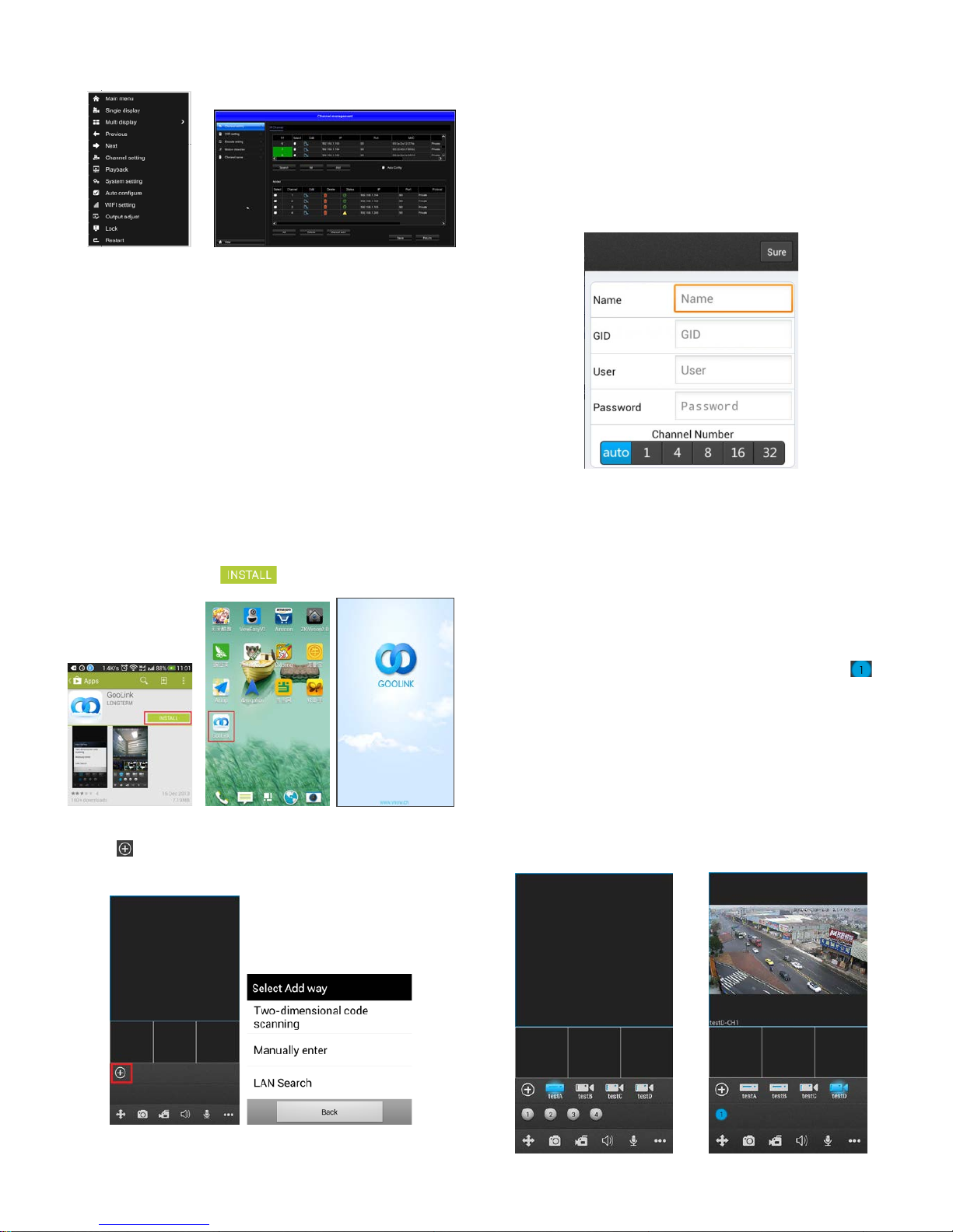
(1)Rlight click menu (2)channel management
(4) channel management function
OSD settings:set name or title to camera
Encode settings: show the camera Coding parameters,su ch as
resolution,bit rat e, frame rate,etc.,besides,you can change it here.
Motion detection:turn motion detecting on or off, and set the
detection area as well as it’s sensitivity.
Channel na me:modify NVR chann el name, the defaut name is
CH1~CH4.
7 Cellphone remote monitor
Step 1:Inst all Goolink software
Method 1:Sanning the Goolink QR code in the user manual or the
system maintenance windows of NVR to download,and install it.
Method 2:Search Keyword “GooLink” in your “Google Play
Store”or APP Store, then tap “ ”to install.
Step 2:Add device
(1) Tap “
” button in the main interface view to open the device adding
view.
(2) Here provides 3 methods to add devices:
Two-dimension al code scanning: Scan the two-dimensional code on
your NVR(in “system maintenance” menu) to fill in the GID string;
Manual enter: Fill in the info manually.The GID is display in system
maintenance menu of NVR.
LAN Search: If the device is on the same local network with your
phone, GooLink would find them.
(3) Input the name(device name),User(device’s login name),and
password.
Notes:the user, password is same as NVR’s login user and password.The
default user is admin,password is blank.
When you finish adding devices, they will show in the main interface
view under the playing windows area. If the device icon’s color is
bright-Blue, it means the device is online.
Step 3:live view
Notes:The circle icon’s color will turn into bright-Blue like
,the
function is on,when it becames grey,the function is off.Please tap the icon
to turn it on or off.
(1) Tap the device icon which you want, GooLink will show the ch annel
icons under the device.
(2) Tap the channel icon which you want, then the channel’s video will
be connected.
(3) Repeat above steps to connect to other channels of the device or
another device.
Tips: You can tap and drag the window to swap any two displaying
videos.
Page 5
Wireless NVR User Guide
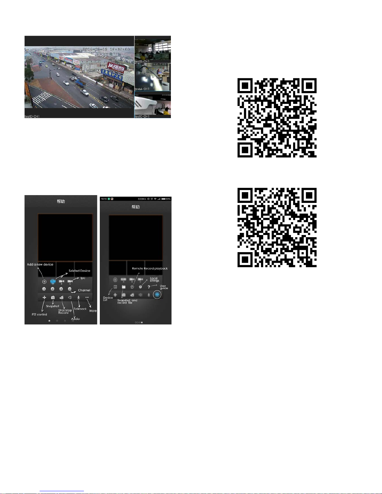
Goolink Function Introduction
In addition, GooLink also supports mobile PTZ , screenshots, video,
editing, local and remote video playback, equipment, and other
functions.When customers click on "help" to help interface, th e interface is
on a variety of icons and buttons functions that can slide around content
view.
Goolink d ownload QR code
For IOS
For Android
Page 6

Wireless NVR User Guide
Please note that
1. The following situations caused by the product failure is not covered by
the warranty:
a. Due to accident s, negligence, disasters, improper operation or incorrect
operation resulting in product failure;
b. Careless use of circumstances or conditions, such as wrong voltage,
ambient temperature, lightning, and lead to product failure;
c. Used by non-factory authorized maintenance unit maintenance products;
d. Beyond promise to change, the warranty period.
2. When users buy the product failure, please user registration card and
dealer or contact technical services throughout the s er vices.
3. When a user provides to the dealer's technical service has any objections,
can complain to the manufactur ers customer support service center.
4. Valid warranty card subject to seal the rear
Warranty car d
User name:________________________________________________
Address:_________________________________________________
Phone:_______________Fax:___________Zip code:_____________
E-mail:__________________________________________________
Product type(Model):_______________________________________
Product number(S/N):___________________________________
Production date :___________ Year __________ Month ___________
Date of purchase:___________ Year __________ Month __________
Free warranty:___________ Month
If you have other requests, please fill in the following:
____________________________________________________________
____________________________________________________________
___________________________________________________
Distributor:_________________ Phone:_________________
Distribution units: (seal)
Maintenance records:
Date The symptom
Maintenance and ser ial
number changes
Note: If a replacement, pl eas e r ecord the original product number;
This distributor retention
 Loading...