


 Loading...
OverlandStorage NEO® 200s/400s Library
User Guide
April 2012
10400367-001

NEO 200s/400s User Guide
©2012 Overland Storage, Inc. All rights reserved.
Overland®, Overland Data®, Overland Storage®, LibraryPro®, LoaderXpress®, Multi-SitePAC®, NEO®, NEO Series®, PowerLoader®, Protection OS®, REO®, REO 4000®, REO Series®, Snap Care®, SnapServer®, StorAssure®, WebTLC®, and XchangeNOW® are registered trademarks of Overland Storage, Inc.
GuardianOS™, SnapWrite™, Snap Enterprise Data Replicator™, SnapExpansion™, SnapSAN™, and SnapServer Manager™ are trademarks of Overland Storage, Inc.
All other brand names or trademarks are the property of their respective owners.
The names of companies and individuals used in examples are fictitious and intended to illustrate the use of the software. Any resemblance to actual companies or individuals, whether past or present, is coincidental.
PROPRIETARY NOTICE
All information contained in or disclosed by this document is considered proprietary by Overland Storage. By accepting this material the recipient agrees that this material and the information contained therein are held in confidence and in trust and will not be used, reproduced in whole or in part, nor its contents revealed to others, except to meet the purpose for which it was delivered. It is understood that no right is conveyed to reproduce or have reproduced any item herein disclosed without express permission from Overland Storage.
Overland Storage provides this manual as is, without warranty of any kind, either expressed or implied, including, but not limited to, the implied warranties of merchantability and fitness for a particular purpose. Overland Storage may make improvements or changes in the products or programs described in this manual at any time. These changes will be incorporated in new editions of this publication.
Overland Storage assumes no responsibility for the accuracy, completeness, sufficiency, or usefulness of this manual, nor for any problem that might arise from the use of the information in this manual.
Overland Storage, Inc. 9112 Spectrum Center Blvd. San Diego, CA 92123 U.S.A.
Tel: 1.877.654.3429 (toll-free U.S.)
Tel: +1.858.571.5555, Option 5 (International) Fax: +1.858.571.0982 (general)
Fax: +1.858.571.3664 (sales) www.overlandstorage.com
10400367-001 04/2012 |
©2012 Overland Storage, Inc. |
W ii |

Preface
Audience and Purpose
This guide is intended for system and network administrators charged with installing and maintaining Overland Storage® NEO 200s/400s libraries on their network. It provides information on the installation, configuration, security, and maintenance of those libraries.
It assumes you are familiar with basic functions of your computer, Serial Attached SCSI (SAS), and Fibre Channel (FC), as well as networking concepts and terminology. It also assumes you are knowledgeable about the Storage Area Network (SAN) to which your NEO S-series library is being connected.
This product is not intended to be connected directly or indirectly, by any means whatsoever, to interfaces of public telecommunications networks.
Product Documentation
NEO product documentation and additional literature are available online. Point your browser to:
http://docs.overlandstorage.com/neo
For additional assistance, search at http://support.overlandstorage.com.
Overland Technical Support
For help configuring and using your NEO 200s/400s libraries, search at: http://support.overlandstorage.com/kb
You can email our technical support staff at techsupport@overlandstorage.com or get additional technical support information on the Contact Us web page:
http://docs.overlandstorage.com/support
For a complete list of support times depending on the type of coverage, visit our website at: http://docs.overlandstorage.com/care
10400367-001 04/2012 |
©2012 Overland Storage, Inc. |
W iii |
NEO 200s/400s User Guide
Conventions
This document exercises several alerts and typographical conventions.
Alerts
Convention |
Description & Usage |
|
|
IMPORTANT |
An Important note is a type of note that provides information essential to |
|
the completion of a task or that can impact the product and its function. |
|
|
CAUTION |
A Caution contains information that the user needs to know to avoid |
|
damaging or permanently deleting data or causing physical damage to |
|
the hardware or system. |
 WARNING ADVERTISSEMENT
A Warning contains information concerning personal safety. Failure to follow directions in the warning could result in bodily harm or death.
Un Canadien avertissement comme celui-ci contient des informations relatives à la sécurité personnelle. Ignorer les instructions dans l'avertissement peut entraîner des lésions corporelles ou la mort.
Typographical Conventions
Convention |
Description & Usage |
|
|
Button_name |
Words in this special boldface font indicate command buttons found in |
|
the Web User Interface. |
|
|
Ctrl-Alt-r |
This type of format details the keys you press simultaneously. In this |
|
example, hold down the Ctrl and Alt keys and press the r key. |
|
|
NOTE |
A Note indicates neutral or positive information that emphasizes or |
|
supplements important points of the main text. A note supplies |
|
information that may apply only in special cases, for example, memory |
|
limitations or details that apply to specific program versions. |
|
|
Menu Flow |
Words with a greater than sign between them indicate the flow of actions |
Indicator (>) |
to accomplish a task. For example, Setup > Passwords > User |
|
indicates that you should press the Setup button, then the Password |
|
button, and finally the User button to accomplish a task. |
|
|
Courier Italic |
A variable for which you must substitute a value |
|
|
Courier Bold |
Commands you enter in a command-line interface (CLI) |
|
|
Information contained in this guide has been reviewed for accuracy, but not for product warranty because of the various environments, operating systems, or settings involved. Information and specifications may change without notice.
Software Updates
The latest release of the NEO 200s/400s firmware can be obtained from the Downloads and Resources – NEO Series page at the Overland Storage website:
http://docs.overlandstorage.com/neo
Follow the appropriate instructions to download the latest software file. For additional assistance, search at http://support.overlandstorage.com/
10400367-001 04/2012 |
©2012 Overland Storage, Inc. |
W iv |

NEO 200s/400s User Guide
Finding More Information
Product documentation related to NEO 200s/400s is listed below. The current versions of all these documents are always available from the Overland Storage NEO Download and Resources website (http://docs.overlandstorage.com/neo).
Source |
Location |
Content |
|
|
|
Quick Start Guide |
Product Packaging |
Provides complete instructions for installing the |
|
and Web |
server into a rack and connecting the server to the |
|
|
network. Also contains links to warranty registration |
|
|
and information. |
|
|
|
User Guide |
eDoc on Web |
Provides an overview of the configuration, |
|
|
maintenance, and troubleshooting of the NEO |
|
|
200s/400s, and detailed instructions on using the |
|
|
remote access Web User Interface. |
|
|
|
Online Help |
Web User |
Basic troubleshooting information embedded in the |
|
Interface |
firmware. |
|
|
|
Electrostatic Discharge Information
A discharge of static electricity can damage static-sensitive devices. Proper packaging and grounding techniques are necessary precautions to prevent damage. To prevent electrostatic damage, observe the following precautions:
•Transport products in static-safe containers such as conductive tubes, bags, or boxes.
•Cover the appliance with approved static-dissipating material.
•Use a wrist strap connected to the work surface and properly-grounded tools and equipment.
•Keep the work area free of non-conductive materials such as foam packing materials.
•Make sure you are always properly grounded when touching a static-sensitive component or assembly. Avoid touching pins, leads, or circuitry.
Safety and Environmental Notices
The sections that follow define each type of safety notice and give examples.
Laser Safety and Compliance
Before using the library, review the following laser safety information.
Class I Laser Product
The library may contain a laser assembly that complies with the performance standards set by the U.S. Food and Drug Administration for a Class I laser product. Class I laser products do not emit hazardous laser radiation. The library has the necessary protective housing and scanning safeguards to ensure that laser radiation is inaccessible during operation or is within Class I limits. External
safety agencies have reviewed the library and have obtained approvals to the latest standards as they apply.
10400367-001 04/2012 |
©2012 Overland Storage, Inc. |
W v |
NEO 200s/400s User Guide
Cautions and Regulatory Compliance Statements for NEBS
This library is NEBS certified. This section includes the cautions and regulatory compliance statements for the Network Equipment-Building System (NEBS) certification from the Telcordia Electromagnetic Compatibility and Electrical Safety – Generic Criteria for Network Telecommunications Equipment (A Module of LSSGR, FR-64; TSGR, FR-440; and NEBSFR, FR-2063) Telcordia Technologies Generic Requirements, GR-1089-CORE, Issue 4, June 2006.
NEBS Compliance Statements
CAUTION: To comply with the Telcordia GR-1089-CORE standard for electromagnetic compatibility and safety, for Ethernet RJ-45 ports, use only shielded Ethernet cables that are
grounded on both ends. In a NEBS installation, all Ethernet ports are limited to intra-building wiring.
CAUTION: The intra-building ports of the equipment or subassembly are only suitable for connection to intra-building or unexposed wiring or cabling. The intra-building ports of the
equipment or subassembly MUST NOT be metallically connected to interfaces that connect to the OSP or its wiring. These interfaces are designed for use only as intra-building interfaces (Type 2 or Type 4 ports as described in GR-1089-CORE, Issue 4), and require isolation from the exposed OSP cabling. The addition of primary protectors is not sufficient protection in order to connect these interfaces metallically to OSP wiring.
An external Surge Protective Device (SPD) is not required for operating this library.
This product can be installed in a network telecommunication facility or location where the NEC applies.
Product Recycling and Disposal
This unit contains recyclable materials.
This unit must be recycled or discarded according to applicable local and national regulations. Overland Storage encourages owners of information technology (IT) equipment to responsibly recycle their equipment when it is no longer needed.
This paragraph is also translated into Spanish (Español) as follows:
Esta unidad debe reciclarse o desecharse de acuerdo con lo establecido en la normativa nacional o local aplicable. Overland Storage recomienda a los propietarios de equipos de tecnología de la información (TI) que reciclen responsablemente sus equipos cuando éstos ya no les sean útiles.
Notice: This mark applies only to countries within the European Union (EU) and Norway.
10400367-001 04/2012 |
©2012 Overland Storage, Inc. |
W vi |
NEO 200s/400s User Guide
Appliances are labeled in accordance with European Directive 2002/96/EC concerning waste electrical and electronic equipment (WEEE). The Directive determines the framework for the return and recycling of used appliances as applicable throughout the European Union. This label is applied to various products to indicate that the product is not to be thrown away, but rather reclaimed upon end of life per this Directive.
Remarque: Cette marque s'applique uniquement aux pays de l'Union Européenne et à la Norvège.
L'etiquette du système respecte la Directive européenne 2002/96/EC en matière de Déchets des Equipements Electriques et Electroniques (DEEE), qui détermine les dispositions de retour et de recyclage applicables aux systèmes utilisés à travers l'Union européenne. Conformément à la directive, ladite étiquette précise que le produit sur lequel elle est apposée ne doit pas être jeté mais être récupéré en fin de vie.
In accordance with the European WEEE Directive, electrical and electronic equipment (EEE) is to be collected separately and to be reused, recycled, or recovered at end of life. Users of EEE with the WEEE marking per Annex IV of the WEEE Directive, as shown above, must not dispose of end of life EEE as unsorted municipal waste, but use the collection framework available to customers for the return, recycling, and recovery of WEEE. Customer participation is important to minimize any potential effects of EEE on the environment and human health due to the potential presence of hazardous substances in EEE. For proper collection and treatment, contact your local Overland representative.
10400367-001 04/2012 |
©2012 Overland Storage, Inc. |
W vii |
Contents
Preface
Chapter 1 – Product Description
Physical Library ...................................................................................................................................................... |
1-1 |
Front Panel ....................................................................................................................................................... |
1-1 |
Rear Panel ....................................................................................................................................................... |
1-3 |
Bar Code Reader ............................................................................................................................................ |
1-5 |
Networking ............................................................................................................................................................ |
1-5 |
Supported Internet Protocols ........................................................................................................................ |
1-5 |
Simple Network Management Protocol (SNMP) Messaging ..................................................................... |
1-5 |
Network Time Protocol (NTP) ......................................................................................................................... |
1-6 |
Maximum Library Storage Capacity and Data Transfer Rate ................................................................... |
1-6 |
Ultrium Tape Drives ............................................................................................................................................... |
1-7 |
Speed Matching ............................................................................................................................................. |
1-7 |
Channel Calibration ....................................................................................................................................... |
1-7 |
Power Management ...................................................................................................................................... |
1-7 |
Media ..................................................................................................................................................................... |
1-8 |
Chapter 2 – User Interfaces
Operator Control Panel ....................................................................................................................................... |
2-1 |
Front Panel LEDs .............................................................................................................................................. |
2-3 |
Input Modes .................................................................................................................................................... |
2-4 |
Web User Interface ............................................................................................................................................... |
2-5 |
Login ................................................................................................................................................................. |
2-6 |
System Status ................................................................................................................................................... |
2-6 |
Web User Interface Help Pages .................................................................................................................... |
2-8 |
Logging out of the Web User Interface ....................................................................................................... |
2-8 |
Chapter 3 – Installation Planning
Determining Number of Logical Libraries .......................................................................................................... |
3-1 |
Basic Guidelines .............................................................................................................................................. |
3-1 |
Library Sharing ................................................................................................................................................. |
3-1 |
Library Partitioning and Element Addressing ..................................................................................................... |
3-1 |
Configuration of a One-Partition System ..................................................................................................... |
3-2 |
Configuration of a Two-Partition System ...................................................................................................... |
3-2 |
Configuration of a Three-Partition System ................................................................................................... |
3-3 |
Configuration of a Four-Partition System ..................................................................................................... |
3-3 |
Using Persistent Binding ........................................................................................................................................ |
3-4 |
Logical Unit Number (LUN) Scanning ................................................................................................................. |
3-4 |
Host Interfaces ...................................................................................................................................................... |
3-4 |
SAS Interface ................................................................................................................................................... |
3-4 |
10400367-001 04/2012 |
©2012 Overland Storage, Inc. |
W v |

NEO 200s/400s User Guide
Fibre Channel Interface ................................................................................................................................. |
3-4 |
Chapter 4 – Installation & Configuration
Choosing a Location ............................................................................................................................................ |
4-1 |
Installing in a Rack ................................................................................................................................................ |
4-2 |
Register to Activate Your Warranty .............................................................................................................. |
4-2 |
Remove the Shipping Lock ............................................................................................................................ |
4-2 |
Rack Installation .............................................................................................................................................. |
4-3 |
Install Any Add-on Components ................................................................................................................... |
4-5 |
Cable Attachment ......................................................................................................................................... |
4-6 |
Power Cord Attachment ............................................................................................................................... |
4-7 |
Configure Library Settings .................................................................................................................................... |
4-8 |
Using Factory Defaults as Your Configuration ............................................................................................. |
4-8 |
Configuring Your Library – Web User Interface ................................................................................................. |
4-8 |
Establishing Remote Access to Your Library ................................................................................................ |
4-9 |
Logging in to the Web User Interface ........................................................................................................ |
4-10 |
Checking Firmware Level ............................................................................................................................ |
4-10 |
Configuring Library Settings ......................................................................................................................... |
4-11 |
Drive Interface Identification and Settings ................................................................................................ |
4-13 |
Configuring Network Settings ...................................................................................................................... |
4-13 |
Configuring User Access .............................................................................................................................. |
4-15 |
Configuring Date and Time Settings ........................................................................................................... |
4-16 |
Configuring Logs and Traces ....................................................................................................................... |
4-16 |
Configuring Email Notifications ................................................................................................................... |
4-17 |
Configuring SMNP Settings .......................................................................................................................... |
4-18 |
Restoring Factory Default Settings .............................................................................................................. |
4-18 |
Logging Out .................................................................................................................................................. |
4-18 |
Configuring Your Library – Operator Control Panel ........................................................................................ |
4-19 |
Logging in to the Operator Control Panel ................................................................................................. |
4-19 |
Configuring Logical Libraries ....................................................................................................................... |
4-19 |
Configuring Library Settings ......................................................................................................................... |
4-20 |
Configuring Drives ........................................................................................................................................ |
4-22 |
Configuring Network Settings ...................................................................................................................... |
4-23 |
Configuring the Access PIN ......................................................................................................................... |
4-24 |
Configuring Save/Restore Settings ............................................................................................................. |
4-25 |
Configuring Date and Time ......................................................................................................................... |
4-27 |
Preparing the Host .............................................................................................................................................. |
4-27 |
Verifying the Connection .................................................................................................................................. |
4-27 |
Cartridge Magazines ......................................................................................................................................... |
4-27 |
2U Library Cartridge Magazines .................................................................................................................. |
4-28 |
2U Library Mail Slot (I/O Station) .................................................................................................................. |
4-28 |
4U Library Cartridge Magazines .................................................................................................................. |
4-29 |
4U Library Mail Slots (I/O Station) ................................................................................................................ |
4-29 |
Populating the Library with Data Cartridges ................................................................................................... |
4-30 |
Inserting the Cleaning Cartridge ...................................................................................................................... |
4-30 |
Registering for Support Notification .................................................................................................................. |
4-31 |
Chapter 5 – Operations
Operator Control Panel Navigation ................................................................................................................... |
5-1 |
Operator Control Panel Menus ........................................................................................................................... |
5-2 |
Monitor Menu .................................................................................................................................................. |
5-2 |
10400367-001 04/2012 |
©2012 Overland Storage, Inc. |
W vi |

NEO 200s/400s User Guide
Control Menu .................................................................................................................................................. |
5-7 |
Configure Menu .............................................................................................................................................. |
5-8 |
Service Menu .................................................................................................................................................. |
5-8 |
Web User Interface Menus ................................................................................................................................ |
5-11 |
Monitor Library Menu ................................................................................................................................... |
5-11 |
Manage Library Menu ................................................................................................................................. |
5-16 |
Configure Library Menu ............................................................................................................................... |
5-17 |
Service Library Menu .................................................................................................................................... |
5-26 |
Import and Export Media during Normal Library Operation ......................................................................... |
5-31 |
Import Media ................................................................................................................................................ |
5-31 |
Export Media ................................................................................................................................................. |
5-32 |
Configuring Mail Slots and Reserving Slots ...................................................................................................... |
5-32 |
Mail Slot Configuration ................................................................................................................................. |
5-32 |
Reserving Slots ............................................................................................................................................... |
5-33 |
Chapter 6 – Media
Data Cartridges .................................................................................................................................................... |
6-2 |
Cartridge Compatibility ................................................................................................................................. |
6-3 |
Capacity Scaling ............................................................................................................................................ |
6-3 |
Write Once, Read Many (WORM) ...................................................................................................................... |
6-3 |
WORM Media .................................................................................................................................................. |
6-3 |
Data Security on WORM Media .................................................................................................................... |
6-3 |
WORM Media Errors ........................................................................................................................................ |
6-4 |
Requirements for WORM Capability ............................................................................................................ |
6-4 |
Cleaning Cartridge .............................................................................................................................................. |
6-4 |
Cartridge Memory Chip (LTO-CM) ..................................................................................................................... |
6-4 |
Bar Code Labels ................................................................................................................................................... |
6-5 |
Guidelines for Using Bar Code Labels .......................................................................................................... |
6-6 |
Write-Protect Switch ............................................................................................................................................. |
6-7 |
Cartridge Care and Handling ............................................................................................................................. |
6-7 |
Provide Training ............................................................................................................................................... |
6-7 |
Ensure Proper Packaging ............................................................................................................................... |
6-8 |
Provide Proper Acclimation and Environmental Conditions ..................................................................... |
6-8 |
Perform a Thorough Inspection ..................................................................................................................... |
6-9 |
Handle the Cartridge Carefully .................................................................................................................. |
6-10 |
Environmental and Shipping Specifications for Tape Cartridges ................................................................. |
6-10 |
Disposing of Tape Cartridges ............................................................................................................................ |
6-10 |
Ordering Media Supplies ................................................................................................................................... |
6-11 |
Chapter 7 – Troubleshooting
Troubleshooting Table .......................................................................................................................................... |
7-1 |
Installation Problems ............................................................................................................................................. |
7-6 |
Library Recovery Problem Determination ......................................................................................................... |
7-7 |
Procedures for Isolating CRU Problems .............................................................................................................. |
7-7 |
Isolating a Power Supply Problem ................................................................................................................ |
7-7 |
Isolating Drive Sled Problems ......................................................................................................................... |
7-9 |
Isolating a Library Controller Card vs. Accessor Enclosure Problem ...................................................... |
7-10 |
Isolating Web User Interface Problems ...................................................................................................... |
7-11 |
Isolating Bar Code Scanner Problems ........................................................................................................ |
7-12 |
Isolating Host Attachment Interface Problems ......................................................................................... |
7-12 |
Identifying a Suspect Cartridge ........................................................................................................................ |
7-12 |
10400367-001 04/2012 |
©2012 Overland Storage, Inc. |
W vii |
NEO 200s/400s User Guide
Contacting Overland Technical Support ........................................................................................................ |
7-13 |
Chapter 8 – Error Codes
Preparing to Resolve an Error Code ................................................................................................................... |
8-1 |
Error Codes ............................................................................................................................................................ |
8-2 |
Sub Error Codes .................................................................................................................................................... |
8-6 |
Warning Events ..................................................................................................................................................... |
8-9 |
Chapter 9 – Service Procedures
Removing Cartridges from Magazine Slots ....................................................................................................... |
9-1 |
Releasing the Magazines Manually ................................................................................................................... |
9-1 |
TotalStorage Tape Diagnostic Tool (ITDT) .......................................................................................................... |
9-2 |
Contacting Overland Technical Support .......................................................................................................... |
9-3 |
Appendix A – Specifications
Physical Specifications ........................................................................................................................................ |
A-1 |
Electrical Specifications ...................................................................................................................................... |
A-1 |
Environmental Specifications ............................................................................................................................. |
A-1 |
Operational Specifications ................................................................................................................................. |
A-2 |
Product Environment .......................................................................................................................................... |
A-3 |
Supported Device Drivers ................................................................................................................................... |
A-3 |
Appendix B – Physical Configurations
2U Library Physical Configuration ....................................................................................................................... |
B-1 |
4U Library Physical Configuration ....................................................................................................................... |
B-2 |
Library Partitioning and Element Addressing ..................................................................................................... |
B-3 |
Partitioning of 2U Libraries .............................................................................................................................. |
B-3 |
Partitioning of 4U Libraries .............................................................................................................................. |
B-3 |
SCSI Element Addressing ............................................................................................................................... |
B-5 |
Appendix C – TapeAlert Flags
Library Supported TapeAlert Flags .................................................................................................................... |
C-1 |
Tape Drive Supported TapeAlert Flags ............................................................................................................. |
C-3 |
Master Glossary & Acronym List
Index
10400367-001 04/2012 |
©2012 Overland Storage, Inc. |
W viii |

Chapter 1
Product Description
The NEO 200s and NEO 400s tape libraries provide compact, high-capacity, low-cost solutions for simple, unattended data backup. The 4U library houses up to 48 tape cartridges (or 45 and an elective 3-tape Mail Slot) in a compact 4U form factor with easy access to cartridges via four removable magazines. The 2U library houses up to 24 tape cartridges (or 23 and an elective 1-tape Mail Slot) in a compact 2U form factor with easy access to cartridges via two removable magazines.
The NEO 200s/400s tape libraries are rack-mountable units that incorporate Ultrium 5 Half-Height or Ultrium 4 Half-Height tape drives. The drives are equipped with a SAS host adapter interface that has a data transfer rate of up to 6.0 Gbps, or a Fibre Channel interface.
Topics in Product Description:
•Physical Library
•Networking
•Ultrium Tape Drives
•Media
Physical Library
These sections describe the physical aspects of the libraries.
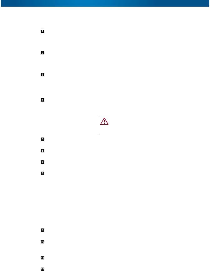
Front Panel
These graphics and table illustrate the front panel components:
10400367-001 04/2012 |
©2012 Overland Storage, Inc. |
W 1-1 |

NEO 200s/400s User Guide |
Physical Library |
Number Item |
Description |
|
|
Power button |
Pressing this button powers ON the library. Pressing and holding |
|
this button for 4 seconds will power OFF the unit (soft power |
|
down). No power switch or button can be found on the back |
|
panel of the library. |
|
|
Front panel LEDs (left to |
• Ready/Activity (Green LED) – It is illuminated any time the unit |
right) |
is powered ON and able to function. It should blink whenever |
|
there is library or drive activity, or when the library is in the |
|
process of powering up. |
|
• Clean Drive (Amber LED) – It is illuminated when the drive |
|
needs to be cleaned. The LED will be turned OFF after the |
|
drive is cleaned successfully. |
|
• Attention (Amber LED) – It is illuminated when there has been |
|
a failure that indicates a piece of media is bad, marginal, or |
|
invalid. It will be cleared when all invalid cartridges have been |
|
exported from the library. The amber LED may also be lit |
|
because a power supply or a power supply fan is failing, or a |
|
drive sled is defective, missing, or has been replaced by a |
|
different drive type. |
|
• Error (Amber LED) – It is illuminated when there is an |
|
unrecoverable library or drive failure. A message is displayed |
|
at the same time on the Operator Control Panel display. |
|
|
Cartridge magazines |
• The 2U library contains two cartridge magazines. |
|
• The left magazine can hold up to 12 cartridges (or 11 |
|
data cartridges and the elective one-slot Mail Slot). |
|
• The right magazine can hold up to 12 cartridges. |
|
• The 4U library contains four cartridge magazines. |
|
• The upper left magazine can hold up to 12 cartridges. |
|
• The lower left magazine can hold up to 12 cartridges (or 9 |
|
data cartridges and the elective three-slot Mail Slot). |
|
• The upper right magazine can hold up to 12 cartridges. |
|
• The lower right magazine can hold up to 12 cartridges. |
|
For more information on magazines, refer to “Cartridge |
|
Magazines” on page 4-27 |
|
|
Air vents |
These vents help keep the library at a normal operating |
|
temperature. |
|
|
10400367-001 04/2012 |
©2012 Overland Storage, Inc. |
W 1-2 |

NEO 200s/400s User Guide |
Physical Library |
Number Item |
Description |
|
|
Control Key buttons |
• UP (+) – The upper left button is used to scroll upward through |
|
menu items. |
|
• DOWN (-) – The lower left button is used to scroll downward |
|
through menu items. |
|
• CANCEL (X) – The upper right button is used to cancel a user |
|
action and return to the previous menu screen. |
|
• SELECT ( ) – The lower right button is used to display a sub- |
|
menu or force an accessor action. |
|
|
Machine Type, Model |
The machine type, model number and serial number of the |
Number, and Serial |
library are located on this label. This serial number is the |
Number label |
number that links the library to your warranty. |
|
|
Operator Control Panel |
This screen is a 128 x 64 pixel monochrome graphic display. |
display |
|
Mail Slot
(I/O Station)
The Mail Slot is used to import and export cartridges into and out of the library.
•The 2U library has an elective 1-tape Mail Slot.
•The 4U library has an elective 3-tape Mail Slot.
Rear Panel
These graphics and table illustrate the rear panel components:
10400367-001 04/2012 |
©2012 Overland Storage, Inc. |
W 1-3 |
NEO 200s/400s User Guide |
Physical Library |
Number Item |
Description |
|
|
|
|
Power connectors |
The libraries require a 110/220 volt AC power connection. |
|
|
• The 2U library has one power supply. |
|
|
• The 4U library has a minimum of one power supply, but has the |
|
|
capability of adding a redundant power supply. |
|
|
|
|
Host interface connectors |
The library has one or more of the following host interface |
|
|
connectors on the drive sled: |
|
|
• SFF-8088 mini-SAS connector |
|
|
• Fibre Channel connector |
|
|
|
|
Tape drive sled |
This library supports the Ultrium 4 and Ultrium 5 tape drives. The |
|
|
tape drive in the library is packaged in a container called a drive |
|
|
sled. Drive sleds come in a full high or Half-Height configuration. |
|
|
The drive sled is a customer replaceable unit (CRU), and is hot- |
|
|
pluggable, which is designed for easy removal and replacement. |
|
|
|
|
Shipping lock and label |
The shipping lock, which secures the accessor during shipping, |
|
storage location |
and associated label are stored on the rear panel of the library for |
|
|
future use. See Removing and Storing the Shipping Lock. |
|
|
|
|
|
CAUTION: The shipping lock must be removed before |
|
|
powering ON the library to allow the accessor to |
|
|
function properly. |
|
|
|
|
|
|
|
USB port |
Used to save/restore library configuration information on a USB |
|
|
device. |
|
|
|
|
Library Control Board |
An LED showing the status of the Library Control Board. The LED |
|
(LCC) LED |
flashing (1 flash per second) is normal operation. |
|
|
|
|
Serial port |
This port is used to communicate serially with the library using an |
|
|
RJ-11 connector. For use by Overland service personnel. |
|
|
|
|
Ethernet port |
This port is used to connect the library to a network. |
|
|
• 10/100 Link LED |
|
|
• Description: Green; indicates link integrity |
|
|
• Flashing: Network synchronization/negotiation |
|
|
• Steady (On): Good connection |
|
|
• Off: No connection between NIC and hub |
|
|
• Activity LED |
|
|
• Description: Amber; indicates port traffic |
|
|
• Flashing: Network traffic present |
|
|
• Steady (On): Heavy network traffic |
|
|
• Off: No traffic |
|
|
|
|
Tape drive LED |
This LED indicates the current status of the drive. When the LED |
|
|
is green, it indicates normal drive activity. |
|
|
|
|
Machine type, Model |
The machine type, model number and serial number of the library |
|
number, and Serial |
are located on this pull-out label. This serial number is the |
|
Number pull-out label |
number that links the library to your warranty. |
|
|
|
|
Fan vents |
These vents allow air to escape from the power supply and tape |
|
|
drive sled. |
|
|
|
|
ESD label |
The Electrostatic Discharge label is a reminder that some of the |
|
|
components of this library are susceptible to electrostatic |
|
|
discharge. See the “Preface.” |
|
|
|
|
10400367-001 04/2012 |
©2012 Overland Storage, Inc. |
W 1-4 |

NEO 200s/400s User Guide |
Networking |
Bar Code Reader
The bar code reader is an integral part of the library accessor. The bar code reader reads each cartridge bar code label that identify the types of cartridge magazines and tape drive installed in the library and provides inventory feedback to the host application, Operator Control Panel, and Web User Interface. The library stores the customized inventory data in memory. Library firmware supports a 6 or 8-character volume serial number (VOLSER) on the bar code label on the tape cartridge.
Networking
This section covers the network supported features and options.
Supported Internet Protocols
The NEO 200s/400s supports the following Internet protocols:
•IPv4
•IPv6
To learn more about IPv4, visit http://www.iana.org/. To learn more about IPv6, visit http://www.ipv6.org/.
Simple Network Management Protocol (SNMP) Messaging
Occasionally, the library may encounter a situation that you want to know about, such as an open magazine or a fault that causes the library to stop. The library provides a standard TCP/IP protocol called Simple Network Management Protocol (SNMP) to send alerts about conditions (such as need for operator intervention) over a TCP/IP LAN network to an SNMP monitoring station. These alerts are called SNMP traps. Using the information supplied in each SNMP trap, the monitoring station (together with customer-supplied software) can alert operations personnel of possible problems or operator interventions that occur.
SNMP Traps
SNMP Traps are alerts or status messages that can be collected, monitored and used to proactively manage attached libraries using SNMP protocol with the SNMP monitoring stations. In summary, each trap provides the following information:
•Product Identification such as product name, description, manufacturer, model number, firmware level, and the URL for which the trap is designated.
•Product Status such as the severity of the trap, status (current and previous), and the time the trap occurred.
•Library State (physical device status) such as identification and status of devices that are monitored. In the case of the library, it would include enclosure, power supply, controller, magazine status, drive count, cartridge slot count, and Mail Slot count. Also included would be certain library statistics, and where appropriate, the fault FSC (fault symptom code) including the severity and description of that fault.
•Drive Status such as the identification of each drive in the library, firmware level, serial number, and other address and status information.
•Trap Definitions such as library status change, open magazine, Mail Slot accessed, hard fault information, drive cleaning requests, excessive retries, and library returning to normal operations.
10400367-001 04/2012 |
©2012 Overland Storage, Inc. |
W 1-5 |

NEO 200s/400s User Guide |
Networking |
•SNMP MIBs: The library's Management Information Base (MIB) contains units of information that specifically describe an aspect of the system, such as the system name, hardware number, or communications configuration. Status and error data is also gathered by MIBs and sent to one or more IP addresses defined during the SNMP configuration operation. Download the SNMP MIB file for this library from http://docs.overlandstorage.com/neo.
SNMP Status Events
This table provides information about SNMP events and the related Trap ID.
Event |
Trap ID |
Definition |
|
|
|
Status Change |
1 |
Library status has changed. |
|
|
|
Door Open |
2 |
Library door has been opened. |
|
|
|
Mail Slot Accessed |
3 |
Library I/O Station has been accessed. |
|
|
|
Fault Posted |
4 |
Library has posted a hard fault/error. |
|
|
|
Request Drive Clean |
5 |
Drive has requested a clean. |
|
|
|
Drive Error |
6 |
Drive has reported an error. |
|
|
|
Loader Retries Excessive |
7 |
Library has reported excessive load retries. |
|
|
|
Loader OK |
8 |
Library has resumed normal operations. |
|
|
|
Account Password Change |
9 |
Account password in the library has changed. |
|
|
|
Configuration Change |
10 |
Library or drive configuration has changed. |
|
|
|
Library Login |
11 |
Someone has logged into the library via the Web User |
|
|
Interface. |
|
|
|
Library Logout |
12 |
Someone has logged out of the library via the Web User |
|
|
Interface. |
|
|
|
Network Time Protocol (NTP)
NTP is an Internet standard protocol that assures accurate synchronization of computer clock times in a network of computers. Running as a continuous background client program on a computer, NTP sends periodic time requests to a server, obtaining server time stamps, and using them to adjust the client's clock.
Maximum Library Storage Capacity and Data Transfer Rate
Maximum library storage capacity and maximum data transfer rates are as follows:
Tape Drive Model |
Host Interface |
||
|
|
|
|
Ultrium 5 |
Half-Height drives |
8 |
Gb/s Fibre Channel – single port |
|
|
6 |
Gb/s SAS – dual port |
|
|
|
|
Ultrium 4 |
Half-Height V2 drives |
8Gb/s Fibre Channel – single port |
|
|
|
6GB/s SAS – dual port |
|
|
|
|
|
10400367-001 04/2012 |
©2012 Overland Storage, Inc. |
W 1-6 |

NEO 200s/400s User Guide |
Ultrium Tape Drives |
Characteristic |
2U Library Specification |
4U Library Specification |
|
|
|
Maximum storage |
• 24 data cartridges |
• 48 data cartridges |
capacity – Ultrium 5 Data |
• Native: 36 TB |
• Native: 72 TB |
Cartridges |
• Compressed: 72 TB |
• Compressed: 144 TB |
|
(2:1 compression) |
(2:1 compression) |
|
|
|
Maximum storage |
• 24 data cartridges |
• 48 data cartridges |
capacity – Ultrium 4 Data |
• Native: 19.2 TB |
• Native: 38.4 TB |
Cartridges |
• Compressed: 38.4 TB |
• Compressed: 75.2 TB |
|
(2:1 compression) |
(2:1 compression) |
|
|
|
Sustained native data |
• LTO 5 Half-Height: 140 MB/s |
|
transfer rate |
• LTO 4 Half-Height: 120 MB/s |
|
|
|
|
Ultrium Tape Drives
The NEO 200s/400s tape libraries support the Ultrium 4 and Ultrium 5 half-height tape drives.
Each tape drive in the library is packaged in a container called a drive sled. The drive sled is a customer replaceable unit (CRU), and is designed for quick removal and replacement of a tape drive.
Both half-height tape drives either support two SAS SFF-8088 connectors that are compatible with SAS-1 cables, or one LC Fibre Channel connector.
NOTE: LTO-4 and LTO-5 SAS and Fibre Channel drives are allowed in the same physical and logical library but it is not recommended.
Speed Matching
To improve system performance, the Ultrium 4 and Ultrium 5 tape drives use a technique called speed matching to dynamically adjust its native (uncompressed) data rate to the slower data rate of the attached server.
Channel Calibration
The channel calibration feature of the Ultrium 4 and Ultrium 5 tape drives customizes each read/write data channel for optimum performance. The customization enables compensation for variations in the recording channel transfer function, media characteristics, and read/write head characteristics.
Power Management
The Ultrium 4 and Ultrium 5 tape drives feature a power management function that controls the drive's electronics so that part of the electronics completely turn OFF when circuit functions are not needed for the drive's operation.
10400367-001 04/2012 |
©2012 Overland Storage, Inc. |
W 1-7 |

NEO 200s/400s User Guide |
Media |
Media
The media used by NEO 200s/400s tape libraries are Ultrium Tape Cartridges that provide up to 1500 GB native capacity (up to 3000 GB with 2:1 hardware data compression) for Ultrium 5 tape drives and 800 GB native capacity (up to 1600 GB with 2:1 hardware data compression) for Ultrium 4 tape drives.
|
|
LTO Ultrium Data Cartridges |
|
||
|
|
|
|
|
|
Ultrium |
1500 GB |
800 GB |
400 GB |
200GB |
100GB |
Tape Drive |
(Ultrium 5) |
(Ultrium 4) |
(Ultrium 3) |
(Ultrium 2) |
(Ultrium 1) |
|
|
|
|
|
|
Ultrium 5 |
Read/Write |
Read/Write |
Read only |
– |
– |
|
|
|
|
|
|
Ultrium 4 |
– |
Read/Write |
Read/Write |
Read only |
– |
|
|
|
|
|
|
Ultrium 3 |
– |
– |
Read/Write |
Read/Write |
Read only |
|
|
|
|
|
|
Ultrium 2 |
– |
– |
– |
Read/Write |
Read/Write |
|
|
|
|
|
|
Ultrium 1 |
– |
– |
– |
– |
Read/Write |
|
|
|
|
|
|
For more detailed information, see Chapter 6, “Media.”
10400367-001 04/2012 |
©2012 Overland Storage, Inc. |
W 1-8 |
Chapter 2
User Interfaces
The library has a local interface (Operator Control Panel), and a remote interface accessed via a web browser (Web User Interface).
The Operator Control Panel is located on the front of the library and allows users to work locally on the library. The Web User Interface allows users and administrators to view and perform some library functions from remote sites.
The Web User Interface is implemented as a Java Applet that runs in a web browser from any PC on the network. The Java Applet requires that Java 1.5.0 or higher be installed on your host computer for full functionality, and is best viewed using Internet Explorer 6.0 or higher. Internet Explorer 7.0 or higher is required for IPv6.
Topics in User Interfaces:
•Operator Control Panel
•Web User Interface
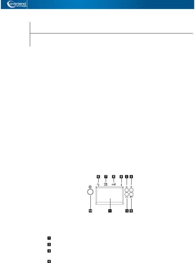
Operator Control Panel
The Operator Control Panel is located on the front bezel of the library. The Operator Control Panel displays library information and menu commands used to execute library management functions in response to the Control Keys (buttons) located on the right of the LCD display.
Operator Control Panel component descriptions:
Number Component |
Description |
|
|
LCD display |
16-character LCD graphic display |
|
|
UP (+) |
Button used to navigate upward (^) through the menu items |
|
|
DOWN (–) |
Button used to navigate downward (V) through the menu |
|
items |
|
|
CANCEL (X) |
Button used to cancel a user action and return to the last |
|
menu item |
|
|
10400367-001 04/2012 |
©2012 Overland Storage, Inc. |
W 2-1 |
NEO 200s/400s User Guide |
Operator Control Panel |
Number Component |
Description |
|
|
SELECT ( ) |
Button used to display a submenu or to select a user action |
|
|
Ready/Activity |
Green LED lit when the unit is powered ON. The LED flashes |
LED |
when there is any library activity or the library is offline. |
|
|
Clean Drive LED |
Amber LED lit when the drive needs cleaning. The LED turns |
|
OFF after the drive is cleaned successfully. |
|
|
Attention LED |
Amber LED lit when a cartridge is bad, marginal, or invalid. |
|
The LED turns OFF when the media is removed from the |
|
drive. The LED may also be lit when there is a power supply |
|
problem. |
|
|
Error LED |
Amber LED lit when there is an unrecoverable library or drive |
|
failure. The corresponding error message appears on the |
|
LCD display. |
|
|
Power ON/OFF |
If the library is OFF, press the button for no more than one |
|
second to start the POST process and power the library ON. |
|
If the library is ON, pressing this button for 4 seconds will |
|
initiate a controlled power down of the library (soft landing). |
|
The following operations will take place before the library |
|
shuts down completely: |
|
• The display indicates with an appropriate message that |
|
the shutdown is in progress. |
|
• The library controller finishes all ongoing library and drive |
|
activities. |
|
• The accessor is moved to its home position. |
|
• The library controller switches OFF the power supply's |
|
secondary side. |
|
NOTE: The shutdown process may be aborted by releasing |
|
the button before 4 seconds has passed. |
|
|
The Operator Control Panel operates in two basic modes:
•User Interaction mode – Mode employed when a user is pushing keys on the Operator Control Panel.
•System Driven mode – Normal mode of operation where the Operator Control Panel displays status in response to commands issued from the drive's internal interface.
When an Operator Control Panel key is pressed and released, the Operator Control Panel automatically transitions to User Interaction mode. User Interaction mode will continue until 3 minutes after a user stops pushing keys, or the requested accessor action stops, whichever is longer, then the Operator Control Panel returns to System Driven mode.
If necessary, the Operator Control Panel will automatically transition to System Driven mode. When this occurs, the library remembers what the user was doing before the display mode changed. Therefore the next button pressed only transitions the Operator Control Panel to the User Interaction mode from the System Driven mode.
Any operational conflict between commands received over the host interface or the Web User Interface and those entered via the Operator Control Panel are avoided with a reservation mechanism on a first-come, first-served basis. Operator Control Panel commands are canceled by an Operator Control Panel logout or timeout.
10400367-001 04/2012 |
©2012 Overland Storage, Inc. |
W 2-2 |
NEO 200s/400s User Guide |
Operator Control Panel |
Library firmware will not allow a user to select an impossible request. Those situations will include, but are not limited to:
•Moving a cartridge from any source to a position occupied by another cartridge
•Moving a cartridge from an empty cartridge position
•Loading a cartridge from any source to a full drive
•Unloading a cartridge from an empty drive
Any error detected by the library or drive controller and not recoverable through predetermined firmware algorithms is considered fatal. When an error occurs, an error code is displayed on the Operator Control Panel display and the error LED is ON. The error code remains on the Operator Control Panel until a key is pressed, which causes the Operator Control Panel to return to the Home Screen. Numeric error codes are used for unrecoverable fatal errors, otherwise text status messages are displayed.
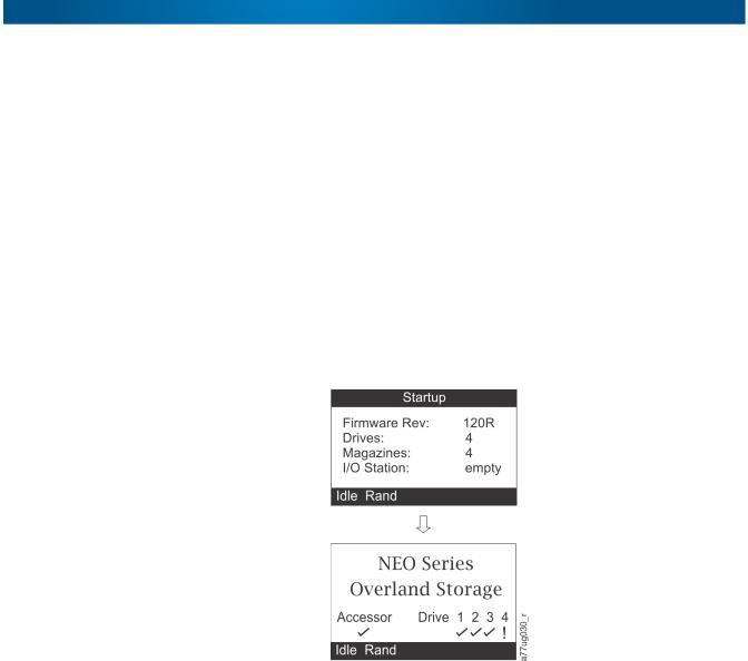
When the library powers ON or resets, it goes through several internally controlled initialization processes, called the Power-On-Self-Test (POST).When the POST is finished, the library displays the Startup screen, then the Home screen.
The Startup screen is the first screen that appears after powering ON the library. It contains the following information:
•Firmware Rev: the current level of library firmware
•Drives: the total number of drives that the library can support
•Magazines: the total number of magazines in the library
•I/O Station: the current status of the Mail Slot
Front Panel LEDs
All LEDs are updated during power ON and reset sequences. Upon power ON or software reset, the library illuminates all LEDs as soon as POST allows. When initialization starts, all LEDs are extinguished and the Ready/Activity LED flashes at a rate of approximately one second per cycle. When the mechanical initialization is complete, the Ready/Activity LED will stop flashing and be constantly illuminated.
If a library failure occurs, the Ready/Activity LED turns OFF and the Error LED turns ON. The Operator Control Panel also displays an appropriate error code to help identify the failure.
The following are additional operational details of LEDs:
10400367-001 04/2012 |
©2012 Overland Storage, Inc. |
W 2-3 |

NEO 200s/400s User Guide |
Operator Control Panel |
•The Ready/Activity LED ( ) is illuminated any time the unit is powered ON and functional. The Ready/Activity LED blinks whenever there is library or drive activity. This LED will also blink when the unit is OFFLINE.
•The Clean LED ( ) is illuminated when either a cleaning requested or a cleaning required flag has been issued by the drive. The LED is turned off after a successful drive cleaning operation.
•The Attention LED ( ) indicates one of the following conditions.
Problem |
Action Required |
|
|
|
|
Bad media |
1. |
Go to Monitor > Inventory to locate the defective |
|
|
cartridge. |
|
2. |
Move the defective cartridge to the Mail Slot. (Operator |
|
|
Control Panel: Control > Move Cartridges). |
|
3. |
Open the Mail Slot to remove the defective cartridge. |
|
|
(Operator Control Panel: Control > Open I/O). |
|
|
|
Drive sled issues |
Do one of the following: |
|
|
• Install a different drive sled. |
|
|
• Modify or resubmit Logical Library setting (Operator Control |
|
|
Panel: Configure > Logical Libraries or Web User |
|
|
Interface: Configure Library > Logical Libraries). |
|
|
• Restore defaults (Operator Control Panel: Configure > |
|
|
Restore Defaults or Web User Interface: Configure |
|
|
Library > Restore Defaults). |
|
|
|
|
Redundant power supply failed |
Complete the following steps: |
|
|
1. |
Replace the failed power supply. |
|
2. |
Cycle library power. |
|
|
|
Power supply fan failure |
Replace the power supply. |
|
|
|
|
•The Error LED ( ) turns ON when there is an unrecoverable drive or library failure. An error message is displayed on the screen and the LED remains ON until the error state is resolved.
NOTE: From the Operator Control Panel, run Service > Library Verify. If Library Verify runs without error, the Error LED turns off. If the error persists, recycle the power.
Input Modes
There are several ways to enter values in the different menu items. These values are selectable predefined values, toggle values (for example, ON/OFF) and numerical values like network addresses.
Selecting Predefined Values
1.To set the predefined values, press the SELECT button to select the menu item.
2.Using the UP and DOWN buttons, select one of the various predefined values for that item.
3.As soon as the Operator Control Panel display shows the correct value, press the SELECT key to apply the value.
10400367-001 04/2012 |
©2012 Overland Storage, Inc. |
W 2-4 |

NEO 200s/400s User Guide |
Web User Interface |
Toggling Values
Toggle values are used to switch between two different states like ON and OFF.
1.After navigating to the menu item, press the SELECT key to select the menu item.
2.Using the UP and DOWN keys, select one of the various predefined states for that item.
3.Press the SELECT key to apply the new state.
Entering Numerical Values
Numerical values are needed for network addresses, password entries, and other configuration entries.
1.After navigating to the menu item, the current value is displayed and the cursor highlights the first digit of the value that can be changed.
2.For each digit to be changed in the value:
a.Use UP and DOWN to increment or decrement the digit.
b.Press SELECT to highlight the next editable digit.
3.Press SELECT at the last digit to apply the complete entry (or press CANCEL to cancel the whole edit process and maintain the original value).
Web User Interface
Many of the same operations performed from the Operator Control Panel can also be performed remotely using the Web User Interface.
The Web User Interface lets you monitor and control your library from any terminal connected to your network or through the World Wide Web (WWW). The Web User Interface hosts a dedicated, protected Internet site that displays a graphical representation of your library.
For static IP Addresses only: After establishing a connection to the library, open any HTML browser and enter the IP address of the library. To configure the Web User Interface, you must first set the IP address using the Operator Control Panel. Refer to “Configuring Network Settings” on page 4-13 or “Configuring Network Settings” on page 4-23.
The Web User Interface Java Applet requires Java 1.5.0 or higher be installed on your host computer for full functionality, and is best viewed using Internet Explorer 6.0 or higher. Internet Explorer 7.0 or higher is required for IPv6. If your computer does not have Java installed or you need to upgrade your installation, download the latest version of the Java Runtime Environment (JRE) for your platform from http://www.java.com/ and follow the instructions provided to enable and configure the Java Runtime Environment for your browser.
The Web User Interface can also be used to update the library and drive firmware, and to download error logs, drive dumps, and other library data from the library.
Before the NEO 200s/400s can be managed over a network using the Web User Interface, you must set up the initial network configuration of the library using the Operator Control Panel.
10400367-001 04/2012 |
©2012 Overland Storage, Inc. |
W 2-5 |

NEO 200s/400s User Guide |
Web User Interface |
Login
IMPORTANT: Some options of the Web User Interface take the library OFFLINE. This inactive mode can interfere with host-based application software, causing data loss. Make sure the library is idle before attempting to perform any remote operations that will take the library OFFLINE.
To login, select the Role type and enter the correct password. There are four levels of access:
•User – Normal user level. The User only has access to Monitor Library menus.
•Superuser – The Superuser has access to the Monitor Library and Manage Library sections.
•Admin – The Admin user level has access to all menus except those restricted to Service only.
•Service – The Service personnel user level access to this level is for Overland Authorized Service personnel only. Service personnel have access to all menus.
Use the default password for logging in as an Admin user is secure.
NOTE: Passwords are case-sensitive.
Each level affects which areas you have access to and what actions you can initiate from those areas.
For DHCP, use the Operator Control Panel to determine the IP Address assigned to your library. Navigate to Monitor > Library > Identity. Scroll down to IP Address and make note of the address. Enter the IP Address in your internet browser address field to access your library with the Web User Interface.
For IPv4 or Dual Stack IPv4 + IPv6, enter your library's static IP Address using the 0.0.0.0 format (four octets).
For IPv6, enter your library's static IP Address or Router Assigned IP Address using the following format: http://[0:0:0:0:0:0:0:0]. To determine your Router Assigned IP Address, navigate to Monitor > Library > Network on the Operator Control Panel. For the IPv6 Router Assigned Addresses to be displayed on the Operator Control Panel, the Network must be configured to IPv6 Only and the Stateless Autoconfig on the must be set to ON.
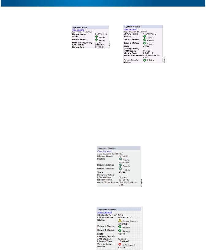
System Status
The System Status screen is always present after login giving current status of the library.
10400367-001 04/2012 |
©2012 Overland Storage, Inc. |
W 2-6 |
NEO 200s/400s User Guide |
Web User Interface |
NEO 200s |
NEO 400s |
Status icons indicate the following conditions.
•The green check mark indicates that the library is fully operational and that no user intervention is required.
•The yellow exclamation point indicates that user intervention is necessary, but that the library is still capable of performing operations. This condition can be caused by a media, library, redundant power supply, power supply fan, or a drive sled problem. To determine which, view the System Status screen.
•The red X indicates that user intervention is required and that the library is not capable of performing operations.
•If Auto Clean is enabled and a cleaning cartridge is not present, or if a cleaning cartridge is present, but not in a reserved slot, Auto Clean status will show Chk Media/Rsvd Slot? and Status will show a green check mark and the words Media Attention.
The Power Supply Status will only appear if redundant power is being utilized with a 4U library. If a redundant power supply fails, the System Status screen appears.
NOTE: The Green LED will be ON on both power supplies. If one Green LEDs is not ON, replace that power supply.
10400367-001 04/2012 |
©2012 Overland Storage, Inc. |
W 2-7 |

NEO 200s/400s User Guide |
Web User Interface |
Web User Interface Help Pages
Each screen on the Web User Interface has an associated Help page. To access a Help page, click Help in the upper right corner of the screen. A new web page will open. Using the left navigation pane, select the desired Help page. To close the Help page, click the red X in the upper right corner of the screen.
Logging out of the Web User Interface
To log out of the Web User Interface, click Logout in the upper right corner of the current screen.
NOTE: If you click the X in the upper right corner of your internet browser window, the screen will close but you will not be logged out of the Web User Interface.
10400367-001 04/2012 |
©2012 Overland Storage, Inc. |
W 2-8 |
Chapter 3
Installation Planning
Before installing your library, take time to review the following information.
Topics in Installation Planning:
•Determining Number of Logical Libraries
•Library Partitioning and Element Addressing
•Using Persistent Binding
•Logical Unit Number (LUN) Scanning
•Host Interfaces
Determining Number of Logical Libraries
You can partition the library into as many logical libraries as there are drives in the library.
Basic Guidelines
•Each logical library must contain at least one drive.
•A library configuration of exactly one logical library equals the entire physical library.
•The library issues a warning to the user if media is moved across logical libraries.
Library Sharing
The library's default configuration allows a single application to operate the library through a single control path. Often, it is advantageous to be able to share a single library between heterogeneous (dissimilar) or homogeneous (similar) applications. Some applications (and some servers) do not allow for sharing a library between systems. Configurations can be created that enable the library to process commands from multiple heterogeneous applications and multiple homogeneous applications.
Configure the library so that it is partitioned into separate logical libraries that independently communicate with separate applications through separate control paths. This configuration requires no special capabilities from the server or application.
Library Partitioning and Element Addressing
A 2U or 4U library system containing more than one drive can be configured into separate logical libraries (create partitions). For the 2U library, one to two partitions are available. For the 4U library, it is possible to configure one to four partitions. Each library must contain at least one drive per partition.
10400367-001 04/2012 |
©2012 Overland Storage, Inc. |
W 3-1 |
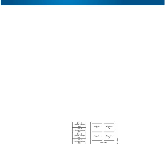
NEO 200s/400s User Guide |
Library Partitioning and Element Addressing |
Partitioning of 2U Libraries
When two half-height drives are installed in a 2U library, the library firmware supports partitioning. The first partition contains the first magazine and the first drive (called Drive 1). The second partition contains the second magazine and the second drive (called Drive 2). The Mail Slot (if configured as Mail Slot) is shared.
Partitioning of 4U Libraries
When one or more half-height drives are added to a 4U library, the library firmware supports partitioning. The first half-height drive in the bottom position is called Drive 1. The half-height drive above it is called Drive 2. And so forth up to four drives.
Mixing of Drives
The libraries support a mix of Ultrium 4 and 5 drives in the same physical library and the same logical library.
NOTE: While the libraries also support a mix of SAS and Fibre Channel drives in the same physical library and same logical library, mixing drive interface types in the same logical library is not recommended.
Configuration of a One-Partition System
A single-partition system configured for a 4U library contains any and all drives present in any drive positions, and all four magazines. When configured with one logical partition, the Element Address assignments will be as follows for the Data Transfer (Drive) Element (DTE) and the Storage Elements (STE):
DTE assignments:
STE assignments:
•Logical Library 1: Slot 1 through 23, 4096 (0x1000) through 4118 (0x1016).
Configuration of a Two-Partition System
A two-partition system must have at least two drives installed. One drive must be installed in either drive position 1 or drive position 2, and another drive must be installed in either drive position 3 or drive position 4. Partition 1 contains any drives in drive position 1 and drive position 2. Partition 1 will also contain magazine 1 and magazine 2. Partition 2 contains any drives in drive position 3 and drive position 4. Partition 2 will also contain magazine 3 and magazine 4.
When configured with two logical partitions, the Element Address assignments will be as follows:
10400367-001 04/2012 |
©2012 Overland Storage, Inc. |
W 3-2 |
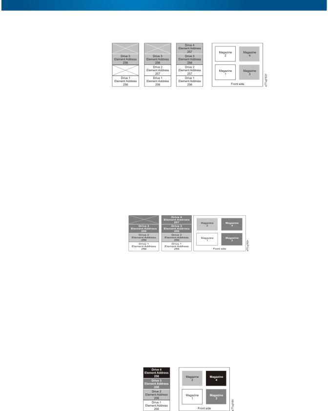
NEO 200s/400s User Guide |
Library Partitioning and Element Addressing |
DTE assignments:
STE assignments:
•Logical Library 1: Slot 1 through slot 21, 4096 (x1000) through 4116 (0x1014)
•Logical Library 2: Slot 22 through slot 45, 4096 (x1000) through 4019 (0x1017)
Configuration of a Three-Partition System
A three-partition system must have at least three drives installed. A drive must be installed in drive position 1, another drive must be installed in drive position 2, and another drive must be installed in either drive position 3 or drive position 4. Partition 1 will contain the first drive and the first magazine. Partition 2 will contain the second drive and the second magazine. Partition 3 will contain any drives in drive position 3 and drive position 4. Partition 3 will also contain magazine 3 and magazine 4.
DTE assignments:
STE assignments:
•Logical Library 1: Slot 1 through slot 9, 4096 (x1000) through 4104 (0x1008)
•Logical Library 2: Slot 10 through slot 21, 4096 (x1000) through 4107 (0x100B)
•Logical Library 3: Slot 22 through slot 45, 4096 (x1000) through 4119 (0x1017)
Configuration of a Four-Partition System
A four partition system must have four drives. Each partition contains one drive and one magazine. When configured with four logical partitions, the Element Address assignments will be as follows:
DTE assignments:
STE assignments:
•Logical Library 1: Slot 1 through slot 9, 4096 (x1000) through 4104 (0x1008)
•Logical Library 2: Slot 10 through slot 21, 4096 (x1000) through 4107 (0x100B)
•Logical Library 3: Slot 22 through slot 33, 4096 (x1000) through 4107 (0x100B)
10400367-001 04/2012 |
©2012 Overland Storage, Inc. |
W 3-3 |
Loading...