

Page 1
User´s Manual
C I - 8 0 6 0
Page 2

Acknowledgements
EPSON is a Trademark of Seiko Epson Corporation.
IBM is a Trademark of International Business Machines Corporation.
ProPrinter is a Trademark of International Business Machines Corporation.
A Publication of
Output Solutions GmbH
Bavierstraße 1
D-40699 Erkrath
Federal Republic of Germany
January 2002
Great care has been taken to ensure that the information in this handbook is accurate and
complete. However, should any errors or omissions be discovered or should any user wish
to make suggestions for improving this handbook, please feel encouraged to send us the
relevant details.
The contents of this manual are subject to change without notice.
Copyright © by Output Solutions GmbH.
All rights strictly reserved. Reproduction or issue to third parties in any form is not
permitted without written authorization from the publisher.
Page 3

Safety Regulations
The printer PP 806 (CI - 8060) fulfills the safety regulations according to UL
1950 and
VDE (IEC 950) and CNA/CSA C22.2 / No. 950 for computer systems.
The mains cable must be connected to a ground protected wall-socket. The
selected voltage of the printer needs to fit to the local voltage.
The power plug must be easily accessible at any time so that it can be
disconnected immediately in case of danger or for maintenance purposes.
Comme le câble de secteur sert de dipositif d'arrêt-urgence, sa connexion à l'imprimante doit être tout le temps accessible.
Before installing the printer, check the surrounding conditions in which the
printer will be placed (see next page, Operating Environment).
During a thunderstorm you should never attempt to connect or disconnect any
data transfer cables.
The power supply should only be opened and checked by authorized personnel.
Repairs and maintenance may only be attempted by authorized personnel as
well. Repairs done inappropriately may cause damage and severe danger for
the user.
There is a warning symbol to draw the user's attention to possible injuries:
This symbol is visible when the rear cover has been
opened. It indicates that the print head is extremely
hot after long periods of printing.
Ce signal de danger se présente quand le cache
derrière de l´imprimante soit retiré pour indiquer que
la tête d´impression peut être extrèmement chaude
après imprimer très longtemps.
I
Page 4

Safety Regulations
Electromagnetic Compatibility
We certify that the equipment at issue,
Type: Printer PP 806 (CI - 8060)
corresponds to the law regulations ruling electromagnetic compatibility of ap-
pliances (89/336/EWG) and, therefore, fulfills the requirements for conformity
marking with the CE-sign.
For standard printer with serial and parallel interface (Ser/Par PM) please note:
This equipment has been tested and found to comply with the limits for a Class
B digital device, pursuant to Part 15 of the FCC rules. These limits are designed
to provide reasonable protection against harmful interference in a residential
installation. This equipment generates, uses, and can radiate radio frequency
energy and, if not installed and used in accordance with the instructions, may
cause harmful interference to radio communications.
However, there is no guarantee that interference will not occur in a particular installation. If this equipment does cause harmful interference to radio or
television reception, which can be determined by turning the equipment off and
on. The user is encouraged to try to correct the interference by one or more of
the following measures:
S Reorient or relocate the receiving antenna.
S Increase the separation between the equipment and receiver.
S Connect the equipment into an outlet on a circuit different from the
circuit to which the receiver is connected.
S Consult the dealer or an experienced radio/TV technician for help.
For printer with all other interface please note:
This equipment has been tested and found to comply with the limits for a Class
A digital device, pursuant to Part 15 of the FCC rules. These limits are designed
to provide reasonable protection against harmful interference when the
equipment is operated in a commercial environment. This equipment generates,
uses, and can radiate radio frequency energy and, if not installed and used in
accordance with the instruction manual, may cause harmful interference to radio
communications.
Operation of this equipment in a residential area is likely to cause harmful inerference in which case the user will be required to correct the interference at his
own expense.
II
Page 5

Safety Regulations
Shielded interface cables should be used with this unit to ensure compliance
with Class B limits.
Changes and modifications not explicitly allowed by the equipment's
manufacturer could void the user's authority to operate the equipment.
Changes et modifications pas expressément approuvés par le producteur
peuvent dévaluer l'autorité d'opérer l'équipement.
Operating Environment
Avoid installing the printer where it is exposed to moisture or heat (eg. direct
sunlight).
S Temperature: + 10 °C to + 35 °C (+50 °F to +95 °F)
S Humidity: 20% to 80%
S Humidity with Automatic
Sheet Feeder (ASF): 30% to 70%
III
Page 6
Safety Regulations
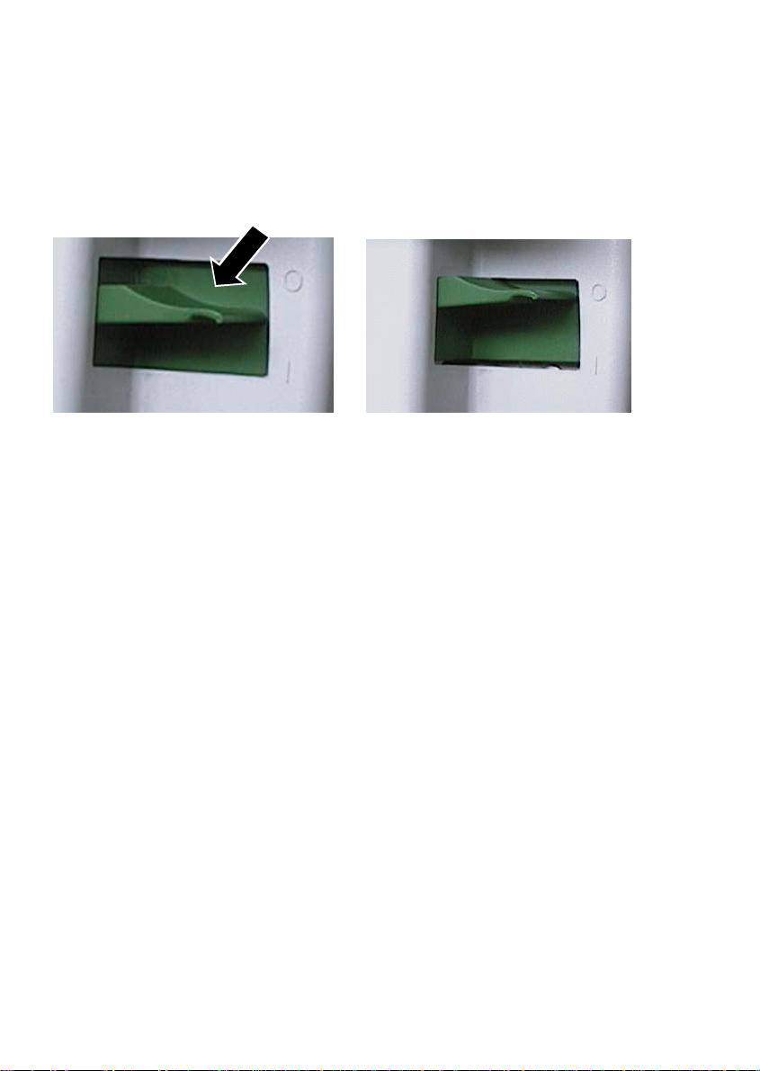
Power On/Off - Lever
To switch the printer on or off push the Power On/Off - Lever always down.
Power - On Power -
Off
Lifting the On/Off - Lever to the zero position won’t switch off the printer. Push
the On/Off - Lever always down for switching on or off.
IV
Page 7

Table of Contents
Preface ...................................................... XI
About this manual .............................................. XI
1.Getting started ............................................. 1-1
1.1 Unpacking ............................................... 1-1
1.2 Requirements to the location of the printer ...................... 1-4
S Environment Conditions .................................. 1-4
S Prconditions for Installation ................................ 1-4
S Power Requiremens ..................................... 1-4
1-3 Remove Transport Lock .................................... 1-5
S Re-packing information .................................. 1-6
1.4 Installing thePersonality Module (PM) .......................... 1-6
1.5 Mains Connection and Power On ............................. 1-7
1.6 Ribbon Installation ........................................ 1-8
1.7 Replacing the Ribbon Cassette .............................. 1-9
1.8 Paper Loading ........................................... 1-10
1.8.1 Paper Source Selection ............................... 1-10
1.8.2 Fanfold Paper Feeding ............................... 1-11
1.8.2 Manual Sheet Feeding ................................ 1-13
1.9 Test-Print Printouts ....................................... 1-14
S Sample: PRINT MENU .................................. 1-15
S Sample:CONFIGURATION ............................... 1-16
S Sample: PRINT LETTER ................................ 1-17
S Sample: PRINT LINES .................................. 1-18
1.10 Connecting to the System .................................. 1-19
S Parallel/Serial Interface .................................. 1-19
1.11 Installing the Printer Drivers ................................ 1-19
1.12 Emulation Selection ...................................... 1-20
V
Page 8

Table of contents
2. Printer Operation ......................................... 2-1
2.1 Operator Panel ........................................... 2-1
2.2 Function Keys ............................................ 2-2
2.2.1 Ready Mode ......................................... 2-4
2.2.2 Local Mode ......................................... 2-4
2.3 Liquid Crystal Display (LCD) ................................. 2-6
2.4 Menu Mode .............................................. 2-8
2.4.1 To Activate the Menu .................................. 2-9
2.4.2 To Confirm Selection ................................. 2-11
2.4.3 How to Save Settings ................................. 2-12
3. Configuring the Printer .................................... 3-1
3.1 What is Configuration ...................................... 3-1
3.2 Standard Configuration ..................................... 3-3
3.3 Explanation of the Printout ................................... 3-4
3.4 Menu Tree ............................................... 3-5
3.5 Menu Item Description ...................................... 3-7
5.5.1 Test Modes ......................................... 3-7
3.5.2 Select Macro ....................................... 3-7
3.5.3 Paper Source ....................................... 3-8
3.5.4 Paper Exit .......................................... 3-8
3.5.5 Print Position Adjustment .............................. 3-9
3.5.6 Page Length ....................................... 3-10
3.5.7 Print Quality ....................................... 3-10
3.5.8 Font ............................................. 3-10
3.5.9 Pitch ............................................. 3-11
3.5.10 Line ............................................. 3-11
3.5.11 Emulation ......................................... 3-11
3.5.12 Character Set ...................................... 3-12
3.5.13 Left Margin ........................................ 3-13
3.5.14 Right Margin ....................................... 3-13
3.5.15 Line Mode ......................................... 3-13
3.5.16 Perforation Skip .................................... 3-14
VI
Page 9

Table of Contents
3.5.17 Tear Off Mode ..................................... 3-14
3.5.18 Interface ......................................... 3-15
3.5.19 Language ........................................ 3-16
3.5.20 Recall Factory ..................................... 3-16
3.5.21 Program Update ................................... 3-16
3.5.22 Menu Access ...................................... 3-16
4 Description of the Individual Menu Items ..................... 4-1
4.1 TEST MODES ............................................ 4-2
4.2 DEFINE MACRO .......................................... 4-3
S SELECT MACRO ................................... 4-3
S PAPER SOURCE ................................... 4-3
S PAPER EXIT ....................................... 4-3
S PRINT POS. ADJ. ................................... 4-4
S PAPGE LENGTH .................................... 4-4
S PRINT QUALITY .................................... 4-5
S FONT ............................................. 4-5
S PITCH ............................................ 4-6
S LINE ............................................. 4-6
S EMULATION ....................................... 4-6
S CHARACTER SET .................................. 4-6
S LEFT MARGIN ...................................... 4-7
S RIGHT MARGIN .................................... 4-7
S LINE MODE ....................................... 4-7
S PERF. SKIP ........................................ 4-8
S TEAR OFF MODE ................................... 4-8
4.3 INTALLATION ............................................ 4-9
S INTERFACE ....................................... 4-9
S I/F TYPE ....................................... 4-9
S WORD LENGTH ................................. 4-9
S BAUD RATE .................................... 4-9
S PARITY BIT .................................... 4-9
S PROTOCOL .................................... 4-9
S DSR / CTS MODE .............................. 4-10
S I / F BUFFER .................................. 4-10
S LANGUAGE ....................................... 4-10
S RECALL FACTORY ................................. 4-10
S PROGRAM UPDATE ................................ 4-10
S MENU ACCESS ................................... 4-10
VII
Page 10

Table of contents
5 Maintenance ............................................. 5-1
S Preferred Materials ...................................... 5-1
5.1 Cleaning the Platen and Surrounding Areas ..................... 5-1
S PRINT MENU ........................................... 5-1
5.2 Cleaning Procedure ........................................ 5-3
S Unlock procedure ....................................... 5-3
5.3 User Replaceable Parts ..................................... 5-5
5.3.1 Print Head Exchange ................................. 5-5
5.3.2 Installing Procedure .................................. 5-7
6. Trouble Shooting and Diagnostics .......................... 6-1
- How to Use this section .................................... 6-1
6.1 Power-related Problems .................................... 6-2
6.2 Error Messages ........................................... 6-2
6.3 No Printout ............................................... 6-7
6.4 Operation-related Problems .................................. 6-8
6.5 Print-related Problems ...................................... 6-9
6.6 Ribbon or Carriage-related Problems ......................... 6-11
6.7 Print Tests .............................................. 6-11
6.8 Diagrams for Failure Analysis ............................... 6-12
6.8.1 Locking Procedure .................................. 6-12
6.8.2 Ribbon Unfasten Procedure ........................... 6-13
6.8.3 Ribbon Error ....................................... 6-14
6.8.4 Remove Paper ..................................... 6-15
6.8.5 Paper Jam TRF .................................... 6-16
6.8.6 Paper Jam ASF or Manual ............................ 6-17
6.8.7 Gap Error ......................................... 6-18
VIII
Page 11

Table of Contents
7 Options ................................................ 7-1
7.1 Printer Stand ............................................. 7-1
7.2 Automatic Sheet Feeder Cassettes (ASF) ...................... 7-3
7.2.1 Checking the Delivery Consignment ..................... 7-3
7.2.2 Prepare the ASF Cassette ............................. 7-4
7.2.3 Installing the ASF Cassette ............................ 7-5
7.2.4 Removing the ASF Cassette ........................... 7-7
7.2.5 Inserting Paper ..................................... 7-8
7.3 Replacement of the ASF Pick-up Rollers ...................... 7-10
7.3.1 To Remove the ASF Pick-up Rollers .................... 7-10
7.3.2 To Install the Pick-up Rollers .......................... 7-11
7.4 Cut Sheet Tray .......................................... 7-12
7.4.1 Installing the Cut Sheet Tray .......................... 7-12
8. Technical Data ........................................... 8-1
8.1 Printer Specification ....................................... 8-1
8.2 Performance ............................................. 8-3
8.3 Paper Handling ........................................... 8-3
8.3.1 Tractor Feed ....................................... 8-4
8.3.2 Manual Insertion .................................... 8-4
8.4 Connectivity ............................................. 8-5
8.4.1 Optional Personality Modules ...........................8.6
8.5 Options ................................................. 8-7
8.5.1 Printer Stand ....................................... 8-7
S Automatic Sheet Feeder Cassette A ........................ 8-7
S Automatic Sheet Feeder Cassette B ........................ 8-8
IX
Page 12

Table of contents
Appendices
Appendix A System Interface Descriptions .......................... A-1
1 Serial Interface RS 232C / RS 422 .......................... A-2
1.1 Interface Characteristics .............................. A-2
1.2 Transmission Protocols and Connection Diagrams .......... A-3
1.2.1 DTR - Ready / Busy .............................. A-3
1.2.2 XON / OXOFF .................................. A-5
1.2.3 Serial Interface with RS-422 .......................A-7
2 Parallel Centronics Interface ..............................A-8
®
2.1 Interface Signal Defination .............................A-8
2.2 Interface Characteristics - Connector Pin assignment ........A-9
2.3 Timing Diagram ....................................A-10
3 Shared Operation ...................................... A-11
Appendix B Print Samples of Resident Fonts ........................ B-1
Appendix C Character Set Tables ..................................C-1
Appendix D IBM ProPrinter Quick Reference .........................D-1
Appendix E EPSON LQ 2550 / ESC/P2 Quick Reference ................ E-1
Appendix F Barcode Quick Reference .............................. F-1
Appendix G Miscellaneous
Information for the System Manager .........................G-1
X
Page 13

Table of Contents
Preface
About this Manual
This manual covers the printer in combination with an interface module (Personality Module).
The Personality Module (PM) is an integral part of the printer, and the type of PM
used significantly influences the behaviour or operation of the printer.
The structure of this manual is such that the operator is led step-by-step through
the various procedures. It starts with the unpacking and setting-up, moves on to
detailed instructions for operating the printer and ends with the mounting of
options.
The manual is divided into the following chapters:
1. Getting Started
This chapter covers the unpacking and setting-up of the printer and the
installation of the PM (Personality Module) and ribbon cassette. By the end
of this chapter the printer should be fully functional and tested in its primary
form. It is not yet connected to the host computer system and no options
are mounted.
2. Operating the Printer
This chapter discusses in great detail the operation of the operator panel,
all menu functions, and the general operation of the menu.
3. Configuring the Printer
This chapter explains how to configure the printer so that it can
communicate with the corresponding system environment. Then this
chapter thoroughly describes the printer's operating controls. In the last
part you will find tables with the possible values of the menu items.
XI
Page 14

Preface
4. Description of the Individual Menu Items
In this chapter you will find a detail explanations of individual menu items.
5. Maintenance
This chapter shows how to clean the printer and how to replace the print
head.
6. Trouble Shooting and Diagnostics suggests how to identify and correct simple problems.
7. Options
This is a brief description of all available options. Supplements enclosed in
the packaging of options may be inserted here.
8. Technical Data
All technical details or data about the printer can be found here.
Appendix A. Interface Description
This chapter gives hints about possibilities to connect the printer to the
various computer systems and explains particularities depending on the
version of the operating system. Additionally, cable connection is
illustrated.
B. Print Samples of Resident Fonts
C. Character Set Table
All printer supported character sets are listed in this chapter.
XII
Page 15

D. Control Codes
Quick reference for IBM Proprinter and IBM Proprinter AGM (4207, 4208
XL 24) Emulation.
E. Control Codes
Quick reference for EPSOM LQ 2550 and ESC/P2 Emulation.
F. Control Codes
Quick reference for Barcode programming.
G. Miscellaneous
S System Manager Information
Preface
XIII
Page 16
Preface
Conventions Used in this Guide
The following conventions are used:
Bold Headlines and important information.
Note: Contains special advice to facilitate handling.
Caution: Contains important information to prevent damage
of the equipment.
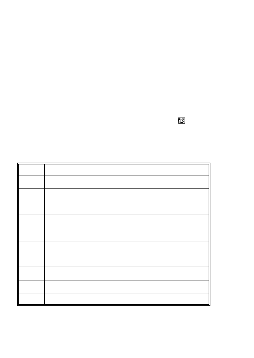
[ENTER] Key functions are always depicted in brackets or
you will find the symbol of the key e.g .
Abbreviations and Acronyms
ASF Automatic Sheet Feeder Cassette for cut sheets and form sets
DRAFT Draft Quality
EE Eastern European
HSD High Speed Draft
LCD Liquid Crystal Display
LED Light Emitting Diode
LQ Letter Quality
MACRO User defined group (1 bis 4) of stored parameter
NLQ Near Letter Quality
PH Print Head
PM Interface (Personality Module)
XIV
Page 17
1. Getting Started
1.1 Unpacking
Check each item against the check list detailed below. Contact your supplier
immediately if any item is missing or damaged.
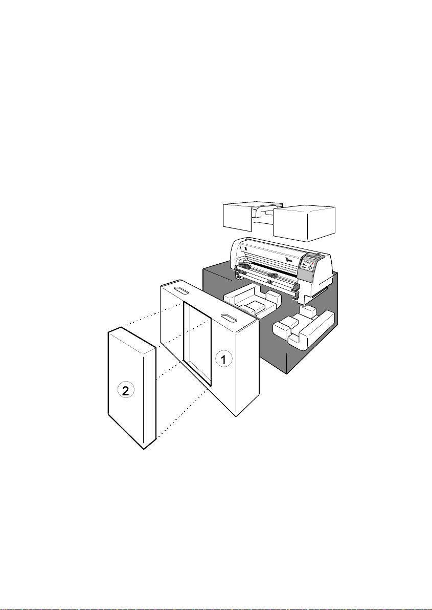
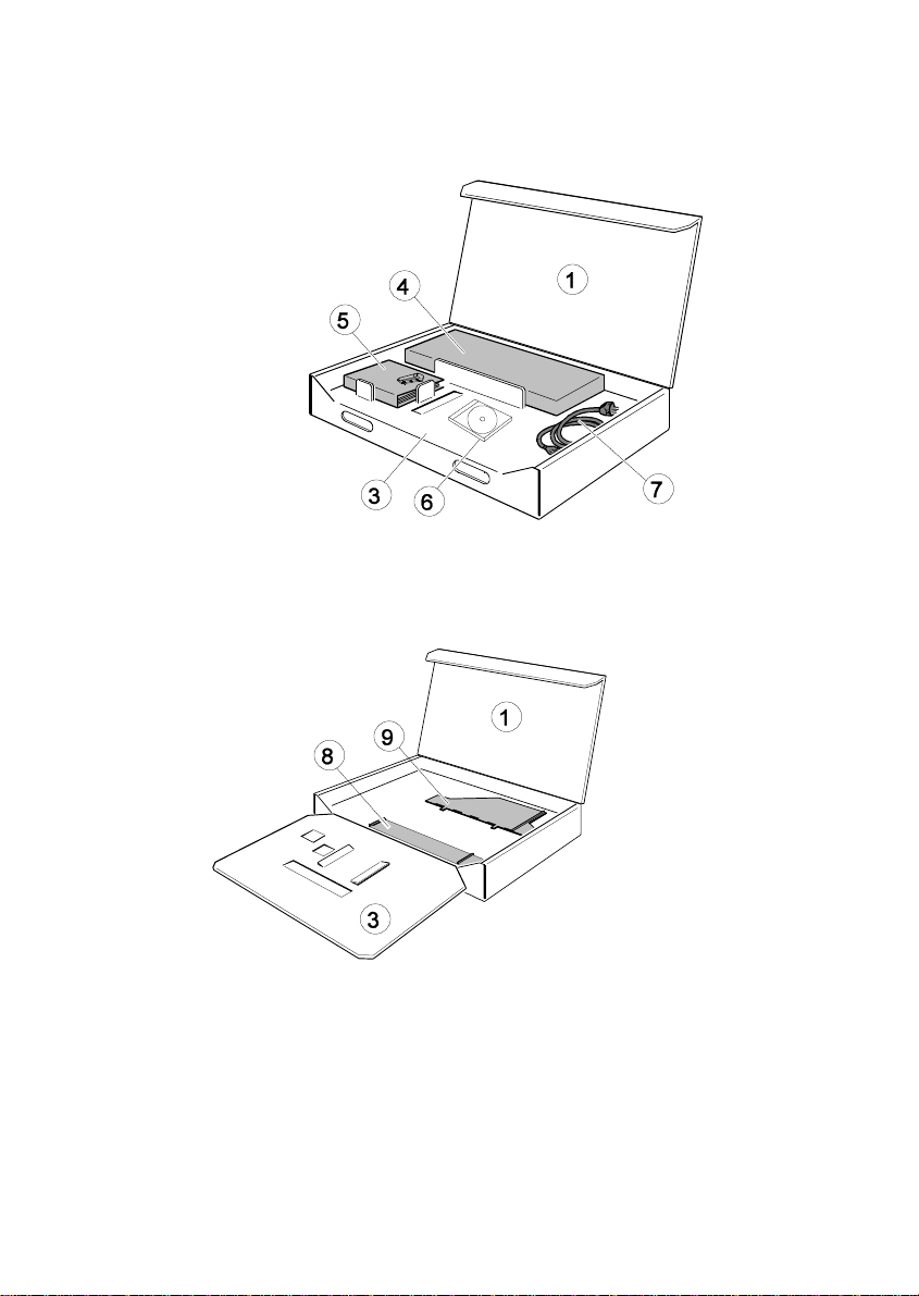
The package contains the printer and a box (1):
Note: Save all packing material and boxes for future transportation of the
printer.
The box (1) contains an additional smaller box (2) with the interface (Personality
Module, PM).
1-1
Page 18
Getting Started
The box (1) contains the following:
First shelf:
S Ribbon Cassette (4)
S Quick Reference Guide (5)
S CD-ROM (6)
S Power cord (7)
Take the parts (4) to (7) out of the package (1) and open the second cover (3).
Second shelf:
Take out the Paper Insertion Guide (8) and the Manual Sheet Feeder (9).
Lowest shelf:
Turn the box (1) and remove the smaller PM box (2) (see page before).
1-2
Page 19
Getting Started
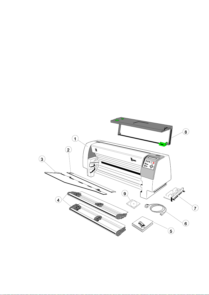
Check each item against the check list detailed below. Contact your supplier
immediately if any item is missing or damaged.
S Printer (1)
S Paper Insertion Guide (2)
S Manual Sheet Feeder (3)
S Two Tractor Cassettes (4)
S Quick Reference Guide (5)
S Power Cord (6)
S Personality Module (PM) (7)
S Ribbon Cassette (8)
S CD-ROM (9)
1-3
Page 20

Getting Started
1.2 Requirements to the location of the printer
Environmental Conditions
S Install the printer in an area away from any heat source, air conditioner, or
strong airflow.
S Avoid installing the printer where it is exposed to moisture or heat (eg. direct
sunlight).
S Avoid installing the printer in a dusty or humid environment.
Preconditions for Installation
S Place the printer on the stand or a table.
S When processing fanfold paper always place the printer with its front edge
slightly off the edge of the table.
Power Requirements
S No special wiring is required. A typical office wall outlet is sufficient.
S Do not plug into the same wall outlet other equipment besides the printer
such as coffee machines, copy machines, or air conditioners.
1-4
Page 21
1.3 Remove Transport Lock
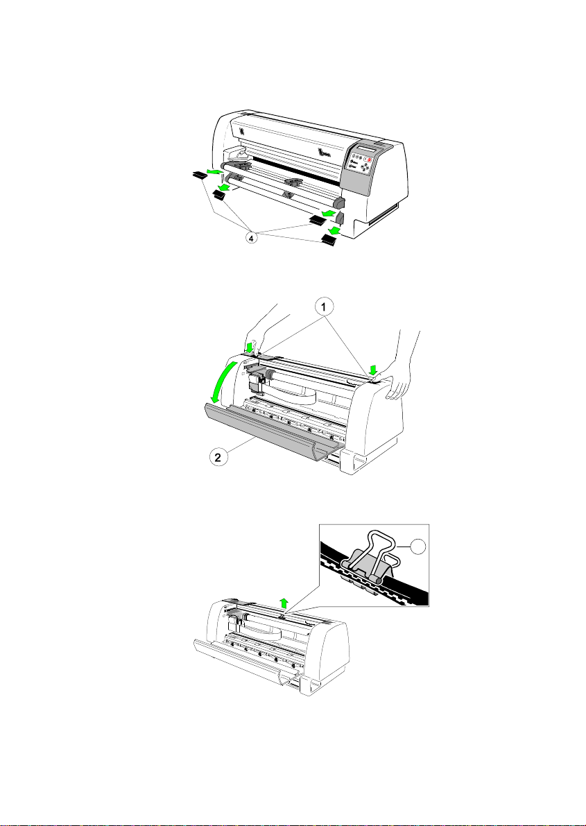
Remove all transport locks (4) of the tractor cassettes.
Getting Started
Open the rear cover (2) by pressing the two locking buttons (1) and swivel the
rear cover backwards.
3
Remove the transport lock (3) for the print head carriage.
1-5
Page 22
Getting Started
Re-packing Information
To ensure maximum protection when transporting the printer, always:
S Remove any installed paper handling option.
S Remove the mains cable.
S Remove the ribbon cassette.
S Reposition the transport lock.
S Pack the printer in its original packing material and ship in its original
package.
1.4 Installing the Personality Module (PM)
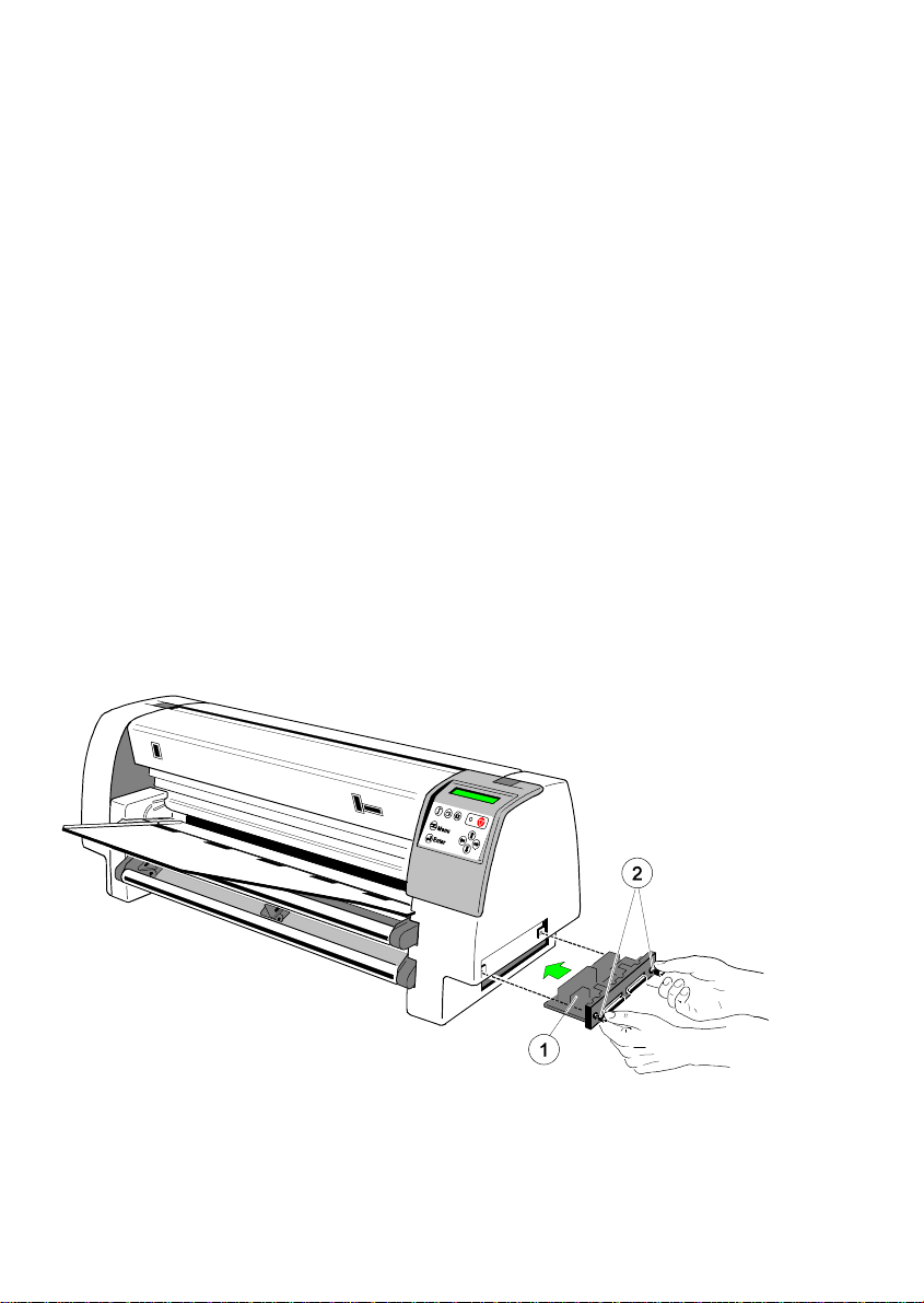
The printer is only operational when an interface is installed, called a Personality
Module (PM). The illustration below shows the standard PM with a serial and
parallel interface.
Note: Never attempt to install or remove a PM while the printer is switched ON.
To avoid damage due to electrostatic discharge, do not touch the pins or
components of the PM.
S Insert the Personality Module (1) with the component side upwards until the
connector fully engages. Hand tighten the two lock screws (2).
1-6
Page 23
Getting Started
1.5 Mains Connection and Power On
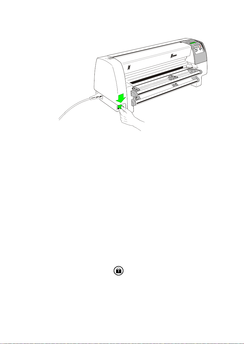
S Connect the printer to the mains using the power cord. First connect the
cable to the power cord socket and then to the mains.
S Do not plug into the same wall outlet other equipment besides the printer
such as coffee machines, copy machines, or air conditioners.
S The power On/Off lever switches the printer‘s power supply ON or OFF.
Note: Press the lever always down.
Since the power cord serves as a safety cut-off, its connection to the
printer must be accessible any time.
When switched ON the printer performs an internal self-test which checks the
electronics, the print head carriage movement, and the interface. Power ON is
indicated by a green LED on the operator panel, the first panel message is
TEST.... .
If the message UNLOCKED - CHECK RIBBON ... is shown, follow the steps in
on page paragraph 1.6 Ribbon Installing.
After inserting the ribbon press to continue. When the internal test has
been completed successfully the display shows READY 1 ELQ or
LOCAL 1 ELQ if data have already been transmitted.
Note: If the display shows anything different please refer to chapter 6 Trouble-
shooting and Diagnostics.
1-7
Page 24
Getting Started
1.6 Ribbon Installation
Note: It is recommended to use only original ribbon cassettes supplied by the
printer manufacturer. Using other ribbons will void your warranty.
The following procedure describes how the ribbon cassette is installed into the
printer for the very first time. Lateron chapter 1.7 Replacing the Ribbon
Cassette is applicable.
Note: The prind head must be always in the park posirtion.
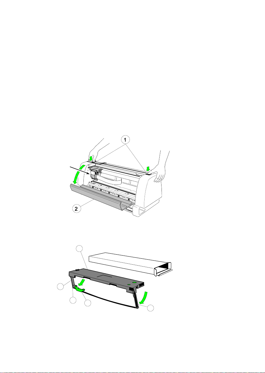
Open the rear cover (2) of the printer by pressing simultaneously the two lokking
buttons (1) and swivel the rear cover backwards.
park position
S Pull the right and left arm (7) of the ribbon cassette (3) to the bottom and
move the ribbon feed guide (4) into the fixing device (5) at the side.
3
7
5
4
Note: The ribbon feed guide (4) has to slide into the fixing device (5). The
7
ribbon shall not be tensed.
1-8
Page 25
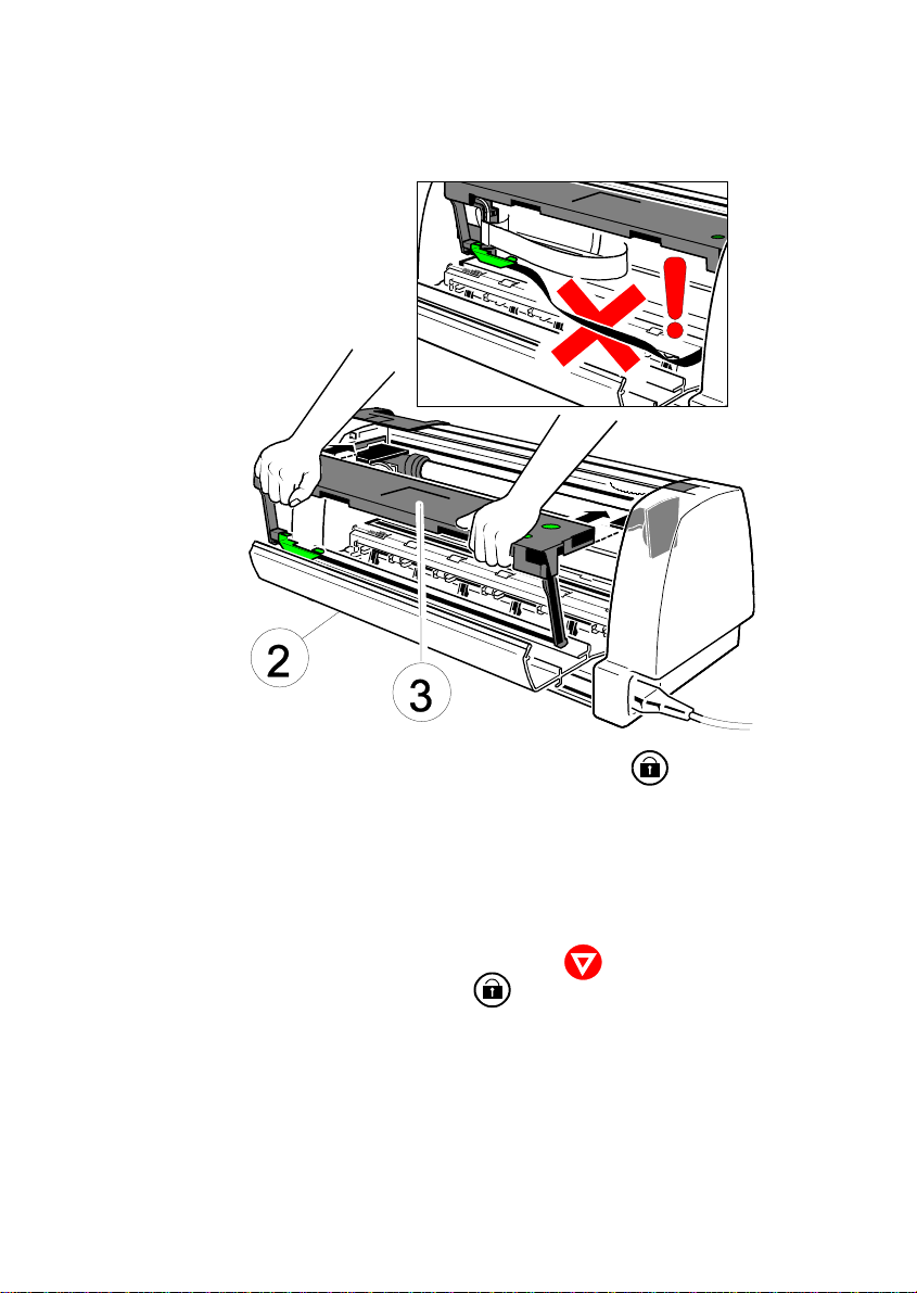
S Slide the ribbon cassette (3) into the printer.
Getting Started
S Close the rear cover (2) and lock the printer (Press ).
1.7 Replacing the Ribbon Cassette
Caution: The print head may be very hot immediately after printing!
S To install the ribbon, the printer must be powered on.
S Put the printer into the Local Mode. (Press ).
S Unlock the rear cover (2). (Press ).
S Open the rear cover (2) of the printer by pressing simultaneously the two
lokking buttons, see picture on page before.
S Swivel the rear cover backwards.
S Remove Ribbon Cassette.
For further steps see chapter 1.6 Ribbon Installation.
1-9
Page 26
Getting Started
1.8 Paper Loading
There are three possibilities for paper feeding:
S Fanfold paper with the two tractor cassettes;
S Single sheets through the manual paper path;
S With the automatic sheet feeder cassettes (ASF-Cassettes, optional). For
further information please refer to chapter 7.2 ASF Cassettes.
1.8.1 Paper Source Selection
The basic selections for PAPER SOURCE are:
S TRACTOR (Default TRACTOR LOWER, indicated by ’)
S MANUAL
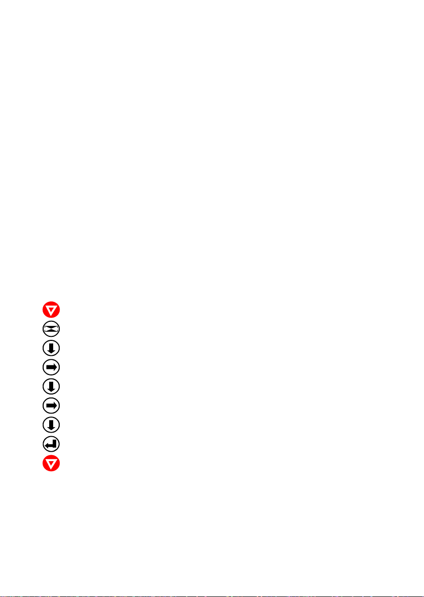
Select 'TRACTOR L/U' as paper source on the operator panel
The following diagram shows which keys to press and what is displayed on the
operator panel.
Power the printer ON:
KEY DISPLAY
[OFFLINE] LOCAL 1 ELQ
[MENU] TEST MODES º
[DOWN] DEFINE MACRO º
[RIGHT] » SELECT MACRO º
[DOWN] » PAPER SOURCE º
[RIGHT] » TRACTOR LOWER r
[DOWN] » TRACTOR L/U
[ENTER] » TRACTOR L/U r
[ONLINE] READY 1 ELQ
Note: The settings selected and confirmed are only active until the printer is
switched off. In order to prevent losing your new settings you can save
them using the function SAVE MENU (see chapter 2.4.3 How to Save
Settings.
1-10
Page 27
Getting Started
1.8.2 Fanfold Paper Feeding
Note: Ensure that all transport locks are removed.
S The printer has to be placed at the front edge of the table or on the printer
stand as described in chapter 7.1 Printer Stand.
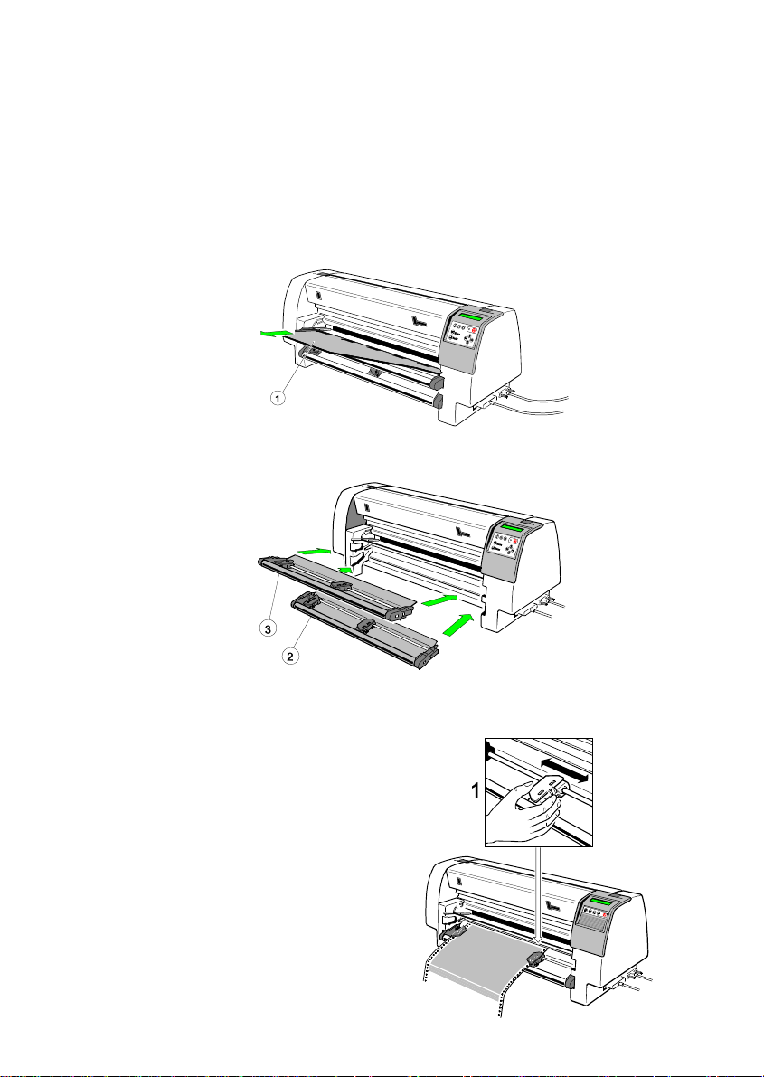
S Remove the manual sheet feeder(1)
S Insert the lower (2) or the upper (3) tractor cassette, or both.
S Step 1: Adjust the tractors roughly to the paper width.
Note: The left tractor is in a fix position.
1-11
Page 28
Getting Started
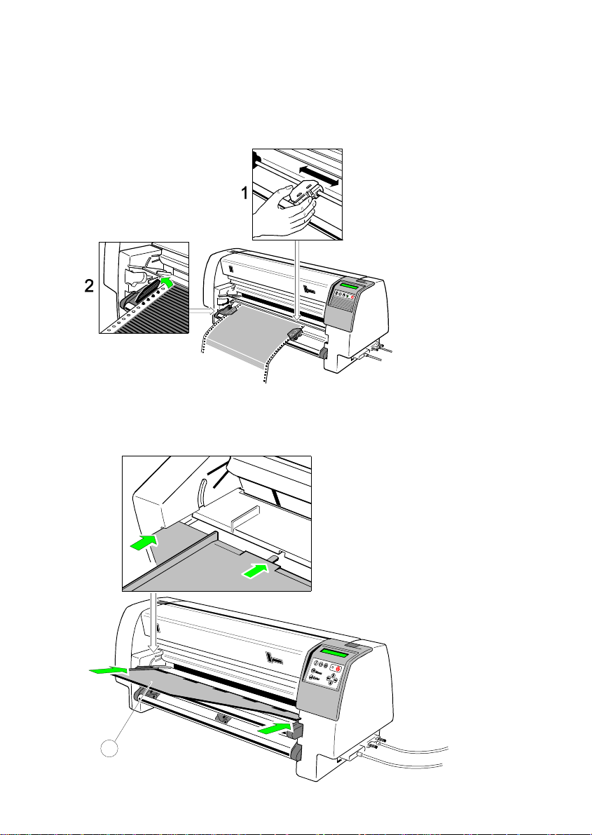
S Step 2: Open the tractor covers, insert the paper, and close the tractor
covers.
S Move the right tractor (1) until the paper is straight but not too tight.
S Insert the Manual Sheet Feeder (4) and initiate a test printout, see chapter
1.9 Test Printouts to check the margins.
1-12
4
Page 29
Getting Started
1.8.3 Manual Sheet Feeding
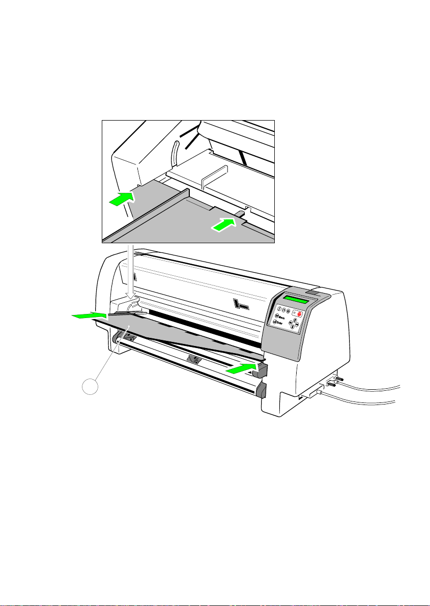
S Insert the Manual Sheet Feeder (1) and connect it to the paper insertion
guide:
1
S Select the paper source MANUAL using either the menu function or by
means of the corresponding command in your application program, see
chapter 1.8.1 Paper Source Selection.
S Initiate a printout, see chapter 1.9 Test Printouts.
1-13
Page 30
Getting Started
1.9 Test Printouts
There are four test printouts available.
S PRINT MENU shows the current settings of all parameters and the contents
of the macros.
S CONFIGURATION lists all available fonts and indicates the page counter va-
lue.
S PRINT LETTER produces a standard letter (ECMA-132) which can be used
for measuring the printer’s throughput.
S PRINT LINES shows a pattern of all printable characters. Use this to check
the print qiality as well as the top and left margin.
The following steps show which keys to use to start a test printout.
The printer feeds paper from the defined paper source (default TRACTOR
LOWER).
KEY DISPLAY
[OFFLINE] LOCAL 1 ELQ
[MENU] TEST MODES º
[RIGHT] » PRINT MENU (or other printout)
1-14
[ENTER] » PRINT MENU r
[ONLINE] PRINT MENU r
(starts printing)
» PRNITMENU
[FORM FEED] TEAR OFF PAPER
(short displayed)
» LOCAL
[ONLINE] READY 1 ELQ
Page 31

Getting Started
Sample: PRINT MENU
PRINT OUT FW-VERSION 20xxxxxx HW-VERSION 29xxxxxx FPGA 4.7 PAGE COUNT 50
INTERFACE
I/F TYPE PARALL./RS232
WORD LENGTH 8 BIT
BAUD-RATE 9600 BIT/S
PARITY BIT EVEN
PROTOCOL DTR
DSR/CTS MODE IGNOR. DSR+CTS
I/F BUFFER 64 KBYTE
MENU ACCESS FULL ACCESS
CURRENT SETTINGS MACRO 1* MACRO 2 MACRO 3 MACRO 4
PAPER SOURCE TRACTOR LOWER TRACTOR LOWER TRACTOR LOWER TRACTOR LOWER TRACTOR LOWER
PAPER EXIT
PATH BATCH BATCH BATCH BATCH BATCH
BATCH CAPACITY - - - - PRINT POS. ADJ.
TRACT.L. V-POS 0.0 0.0 0.0 0.0 0.0
TRACT.L. H-POS 0.0 0.0 0.0 0.0 0.0
TRACT.U. V-POS 0.0 0.0 0.0 0.0 0.0
TRACT.U. H-POS 0.0 0.0 0.0 0.0 0.0
MANUAL V-POS 0.0 0.0 0.0 0.0 0.0
MANUAL H-POS 0.0 0.0 0.0 0.0 0.0
BIN 1 V-POS 0.0 0.0 0.0 0.0 0.0
BIN 1 H-POS 0.0 0.0 0.0 0.0 0.0
BIN 2 V-POS 0.0 0.0 0.0 0.0 0.0
BIN 2 H-POS 0.0 0.0 0.0 0.0 0.0
BIN 3 V-POS 0.0 0.0 0.0 0.0 0.0
BIN 3 H-POS 0.0 0.0 0.0 0.0 0.0
PAGE LENGTH 72 LINES 72 LINES 72 LINES 72 LINES 72 LINES
FONT QUALITY LQ LQ LQ LQ LQ
GRAPHICS QUALITY STANDARD STANDARD STANDARD STANDARD STANDARD
FONT DATA DATA DATA DATA DATA
PITCH 10 CPI 10 CPI 10 CPI 10 CPI 10 CPI
LINE 6 LPI 6 LPI 6 LPI 6 LPI 6 LPI
EMULATION EPSON LQ EPSON LQ IBM PROPR. IBM PROPR. AGM EPSON LQ
CARACTER SET EPSON EXT. GCT EPSON EXT. GCT IBM SET 2 IBM SET 2 EPSON EXT. GCT
LEFT MARGIN 1. COLUMNS 1. COLUMNS 1. COLUMNS 1. COLUMNS 1. COLUMNS
RIGHT MARGIN 165. COLUMNS 165. COLUMNS 165. COLUMNS 165. COLUMNS 165. COLUMNS
LINE MODE LF=LF, CR=CR LF=LF, CR=CR LF=LF, CR=CR LF=LF, CR=CR LF=LF, CR=CR
PERF. SKIP YES YES YES YES YES
TEAR-OFF-MODE NO NO NO NO NO
1: U.S.A. 1: U.S.A. 1: U.S.A. 1: U.S.A. 1: U.S.A.
Note: An asterisk (’) after MACRO 1 indicates the actual macro
The values after FW- and HW-VERSION indicates the actual release.
All this standard settings of the firmware will be restored with the menu function
RECALL FACTORY.
1-15
Page 32

Getting Started
Sample: CONFIGURATION
CONFIGURATION FW-VERSION 202xxxxx PAGE COUNT 126
C031 ISO 8859/1 CO32 ISO 8859/15 C061 IBM SET 1
C062 IBM SET 2 C063 IBM CODE PAGE C071 EPSON EXT. GCT
C100 CODE PAGES EE C101 CODE PAGES EE2
DATA ROMAN NLQ ROMAN LQ
SAN SERIF NLQ SAN SERIF LQ COURIER NLQ
COURIER LQ PRESTIGE NLQ PRESTIGE LQ
SCRIPT NLQ SCRIPT NQ OCR B LQ
OCR A LQ ORATOR-C NLQ ORATOR-C LQ
ORATOR NLQ ORATOR LQ DATA LARGE LQ
ZEICHENSATZ : EPSON EXT. GCT 1: U.S.A.
PRINTHEAD NEEDLE
1 2 3 4 5 6 7 8 9 10 11 12 13 14 15 16 17 18 19 20 21 22 23 24
DATA DRAFT
$ !"#$%&'()*+,-./01234567890:;<=>?@ABCDEF.......
.
.
The value after FW-VERSION indicates the actual release of the firmware.
1-16
Page 33

Sample: PRINT LETTER
Eilzustellung
Norddeutsche Farbwerke KG
Herrn Dr. Grauert
Große Elbstraße 64
2000 Hamburg 4
Org. III 5/37 H-A 4 34 22.04.75
17.04.75Volkmann
Vordruckgestaltung für den allgemeinen Schriftverkehr, für das Bestell- und Rechnungswesen E i l t
Sehr geehrter Herr Dr. Grauert,
Sie können das Schreiben der Briefe, Bestellungen, Rechnungen usw.
sowie das Bearbeiten des Schriftguts rationalisieren, wenn die
Vordrucke Ihres Unternehmens den folgenden Normen entsprechen:
DIN 676 Geschäftsbrief; Vordrucke A4
DIN 677 -; Vordruck A5
DIN 679 Geschäftspostkarte; Vordrucke A6
DIN 4991 Vordrucke im Lieferantenverkehr; Rechnung
DIN 4992 -; Bestellung (Auftrag)
DIN 4993 -; Bestellungsannahme (Auftragsbestätigung)
DIN 4994 -; Lieferschein/Lieferanzeige
DIN 4998 Entwurfsblätter für Vordrucke
Diese Normen enthalten alle Einzelheiten für den sinnvollen und
zweckmäßigen Aufdruck. Wenn dazu bei der Beschriftung genormter
Vordrucke DIN 5008 'Regel für Maschinenschreiben' beachtet wird,
entstehen übersichtliche und werbewirksame Schriftstücke.
Die beifgefügten 6 Mustervordrucke zeigen, daß das Beachten der
Normen die künstlerische und werbewirksame Gestaltung der Vordrucke nicht ausschließt.
Da wir uns auf die Herstellung genormter Vordrucke spezialisiert
haben, können wir besonders billig liefern. Eine Probestellung
wird Sie und Ihre Geschäftsfreunde von den Vorteilen überzeugen.
Mit bester Empfehlung
NORAG
Druckerei und Verlagshaus KG
Getting Started
Herrmann
Anlagen
6 Mustervordrucke
Note: By pressing the key the print job will be interrupted and then with
the following key sequence and terminated.
1-17
Page 34

Getting Started
Sample: PRINT LINES
ABCDEFGHIJKLMNOPQRSTUVWXYZabcdefghijklmnopqrstuvwxyz0123456789!§
§ABCDEFGHIJKLMNOPQRSTUVWXYZabcdefghijklmnopqrstuvwxyz0123456789!
!§ABCDEFGHIJKLMNOPQRSTUVWXYZabcdefghijklmnopqrstuvwxyz0123456789
9!§ABCDEFGHIJKLMNOPQRSTUVWXYZabcdefghijklmnopqrstuvwxyz012345678
89!§ABCDEFGHIJKLMNOPQRSTUVWXYZabcdefghijklmnopqrstuvwxyz01234567
789!§ABCDEFGHIJKLMNOPQRSTUVWXYZabcdefghijklmnopqrstuvwxyz0123456
6789!§ABCDEFGHIJKLMNOPQRSTUVWXYZabcdefghijklmnopqrstuvwxyz012345
56789!§ABCDEFGHIJKLMNOPQRSTUVWXYZabcdefghijklmnopqrstuvwxyz01234
456789!§ABCDEFGHIJKLMNOPQRSTUVWXYZabcdefghijklmnopqrstuvwxyz0123
3456789!§ABCDEFGHIJKLMNOPQRSTUVWXYZabcdefghijklmnopqrstuvwxyz012
23456789!§ABCDEFGHIJKLMNOPQRSTUVWXYZabcdefghijklmnopqrstuvwxyz01
123456789!§ABCDEFGHIJKLMNOPQRSTUVWXYZabcdefghijklmnopqrstuvwxyz0
0123456789!§ABCDEFGHIJKLMNOPQRSTUVWXYZabcdefghijklmnopqrstuvwxyz
z0123456789!§ABCDEFGHIJKLMNOPQRSTUVWXYZabcdefghijklmnopqrstuvwxy
yz0123456789!§ABCDEFGHIJKLMNOPQRSTUVWXYZabcdefghijklmnopqrstuvwx
xyz0123456789!§ABCDEFGHIJKLMNOPQRSTUVWXYZabcdefghijklmnopqrstuvw
wxyz0123456789!§ABCDEFGHIJKLMNOPQRSTUVWXYZabcdefghijklmnopqrstuv
vwxyz0123456789!§ABCDEFGHIJKLMNOPQRSTUVWXYZabcdefghijklmnopqrstu
uvwxyz0123456789!§ABCDEFGHIJKLMNOPQRSTUVWXYZabcdefghijklmnopqrst
tuvwxyz0123456789!§ABCDEFGHIJKLMNOPQRSTUVWXYZabcdefghijklmnopqrs
stuvwxyz0123456789!§ABCDEFGHIJKLMNOPQRSTUVWXYZabcdefghijklmnopqr
rstuvwxyz0123456789!§ABCDEFGHIJKLMNOPQRSTUVWXYZabcdefghijklmnopq
qrstuvwxyz0123456789!§ABCDEFGHIJKLMNOPQRSTUVWXYZabcdefghijklmnop
pqrstuvwxyz0123456789!§ABCDEFGHIJKLMNOPQRSTUVWXYZabcdefghijklmno
opqrstuvwxyz0123456789!§ABCDEFGHIJKLMNOPQRSTUVWXYZabcdefghijklmn
nopqrstuvwxyz0123456789!§ABCDEFGHIJKLMNOPQRSTUVWXYZabcdefghijklm
mnopqrstuvwxyz0123456789!§ABCDEFGHIJKLMNOPQRSTUVWXYZabcdefghijkl
lmnopqrstuvwxyz0123456789!§ABCDEFGHIJKLMNOPQRSTUVWXYZabcdefghijk
klmnopqrstuvwxyz0123456789!§ABCDEFGHIJKLMNOPQRSTUVWXYZabcdefghij
jklmnopqrstuvwxyz0123456789!§ABCDEFGHIJKLMNOPQRSTUVWXYZabcdefghi
ijklmnopqrstuvwxyz0123456789!§ABCDEFGHIJKLMNOPQRSTUVWXYZabcdefgh
hijklmnopqrstuvwxyz0123456789!§ABCDEFGHIJKLMNOPQRSTUVWXYZabcdefg
ghijklmnopqrstuvwxyz0123456789!§ABCDEFGHIJKLMNOPQRSTUVWXYZabcdef
fghijklmnopqrstuvwxyz0123456789!§ABCDEFGHIJKLMNOPQRSTUVWXYZabcde
efghijklmnopqrstuvwxyz0123456789!§ABCDEFGHIJKLMNOPQRSTUVWXYZabcd
defghijklmnopqrstuvwxyz0123456789!§ABCDEFGHIJKLMNOPQRSTUVWXYZabc
cdefghijklmnopqrstuvwxyz0123456789!§ABCDEFGHIJKLMNOPQRSTUVWXYZab
bcdefghijklmnopqrstuvwxyz0123456789!§ABCDEFGHIJKLMNOPQRSTUVWXYZa
Note: By pressing the key the print job will be interrupted and then with
the following key sequence and terminated.
1-18
Page 35
Getting Started
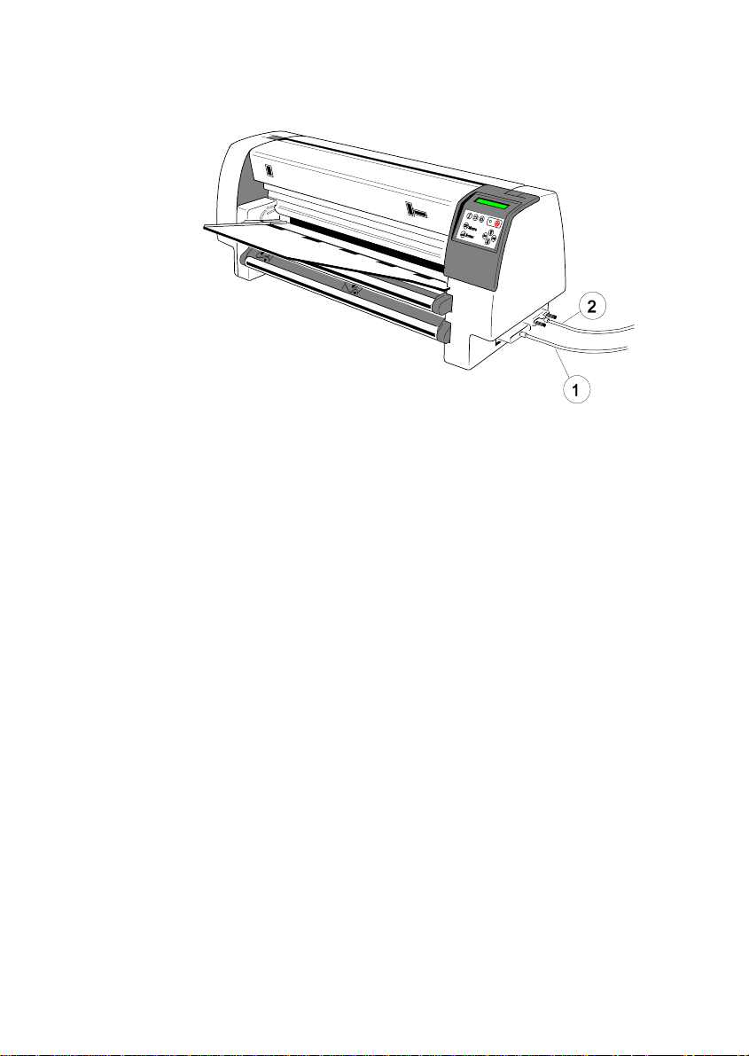
1.10 Connecting to the System
Parallel/Serial Interface
S Switch the printer and the computer OFF.
S Connect the interface cable coming from the computer to the printer's
parallel (1) or serial (2) port.
The following values are default settings, see test printout PRINT MENU on
page 1-15
S Word Length: 8 bit
S Baud-Rate 9600 BPS
S Parity Bit: Even
S Protocol DTR
S DSR/CTS Mode Ignore DSR+CTS
S I/F Buffer 64 K-Byte
After powering the printer ON both interfaces, serial and parallel, are available
for data transfer because of the shared mode. The port to which data is sent
becomes active automatically.
For changing the parameters, see Appendix A System Interface Description
1.11 Installing the Printer Drivers
S You will find the printer drivers on the CD-ROM.
1-19
Page 36

Getting Started
1.12 Emulation Selection
The following emulations are included in the PM Ser/Par:
S EPSON LQ / ESC/P2 in Macro 1 (Default)
S IBM ProPrinter XL 24 in Macro 2
S IBM ProPrinter XL 24 AGM in Macro 3
S EPSON LQ / ESC/P2 in Macro 4
To change from one emulation to another, follow the procedure below. The example shows the keys to press along with the display information for a change
from EPSON LQ / ESC/P2 in Macro 1 to IBM ProPrinter in Macro 2.
Switch the printer ON. The display shows READY 1 ELQ.
KEY DISPLAY
[OFFLINE] LOCAL 1 ELQ
[MACRO SELECTION] MACRO 2 r
(hold the key down and the available marcos are scrolling in the
display and stop pressing with selected Macro 2)
[ONLINE] READY 2 IPP
The information READY 2 IPP indicates the selected macro and the
emulation of this macro, for example:
1 ELQ Macro 1 with Epson Emulation
2 IPP Macro 2 with IBM Proprinter Emulation
3 AGM Macro 3 with IBM Proprinter AGM Emulation
4 ELQ Macro 4 with Epson Emulation.
Note: A “Macro“ is a summary of application specific parameter settings. It is
possible to have a total of four macros, each with a different summary of
VALUE settings.
The settings selected and confirmed are only active until the printer is
switched off. In order to prevent losing your new settings you can save
them using the function SAVE MENU (see chapter 2.4.3 How to Save
Settings.
1-20
Page 37
2. Printer Operation
Mos of the printer functions could be executed via operator panel as well as via
software commands from the host system. Some functions become only
effective with Operator Panel keys, for example: locking/unlocking the printer.
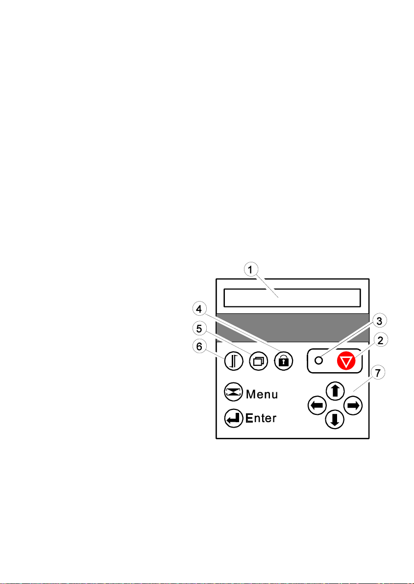
2.1Operator Panel
The Operator Panel
S controls the set-up for communication with the host computer;
S controls various parameter settings;
S allows manual control of the paper handling;
S gives information about the printer's status.
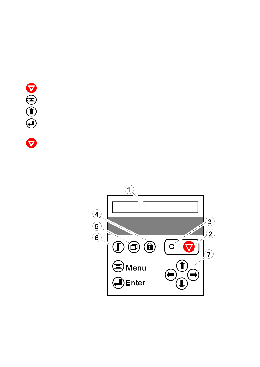
1 LCD Display
2 Online / Offline
3 LED
4 Lock / Unlock Cover
Lock/ Unlock Print Head
5 Macro Selection
6 Form Feed
7 Curser Keys for Navigation
in the Menu Mode
The LCD Display (1) indicates the current status of the printer. If any error
occurs (e.g. UNLOCKED - ... CHECK RIBBON) the corresponding error
message will be displayed. The green LED (3) lights only if the printer is
powered on and in the Ready Mode.
2-1
Page 38
Printer Operating
2.2Function Keys
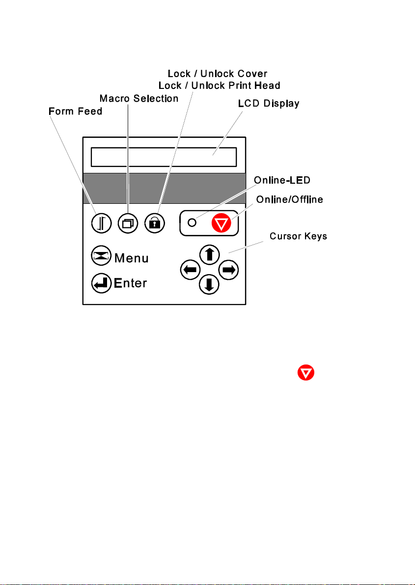
If the printer is powered on, the display shows READY 1 ELQ and the green
LED lights. The printer is in the Ready Mode.
The printer works in two different modes, the Ready Mode and the Local Mode.
To put the printer into the Local Mode, press the Online / Offline-key .
Ready Mode
In this mode only the red [Online/Offline] key is active and the green LED lights.
By pressing the key the printer changes into the Local Mode and the green
Online-LED extinguishes. Further information see chapter 2.2.1.
Local Mode
Depending on the state of the printer the three leftmost keys have multiple
functions. The functions are displayed by keeping the appropriate key pushed.
Release the key as soon as the desired function is displayed. Further
information see chapter 2.2.2 .
2-2
Page 39
KEY DISPLAY
[Form Feed] EJECT PAPER )
INSERT MANUAL )
INSERT TRACTOR )
INSERT TRACTOR U(pper) )
INSERT TRACTOR L(ower) )
PAPER TEAR OFF
PAPER PARK
FORM FEED
REV. FORM FEED
[Macro Selection] MACRO 1
MACRO 2
MACRO 3
MACRO 4
[Lock Cover/ LOCK COVER
Unlock Cover] UNLOCK COVER
UNLOCK COVER/ PH
Printer Operating
1
1
1
1
1
Note: PH means Print Head
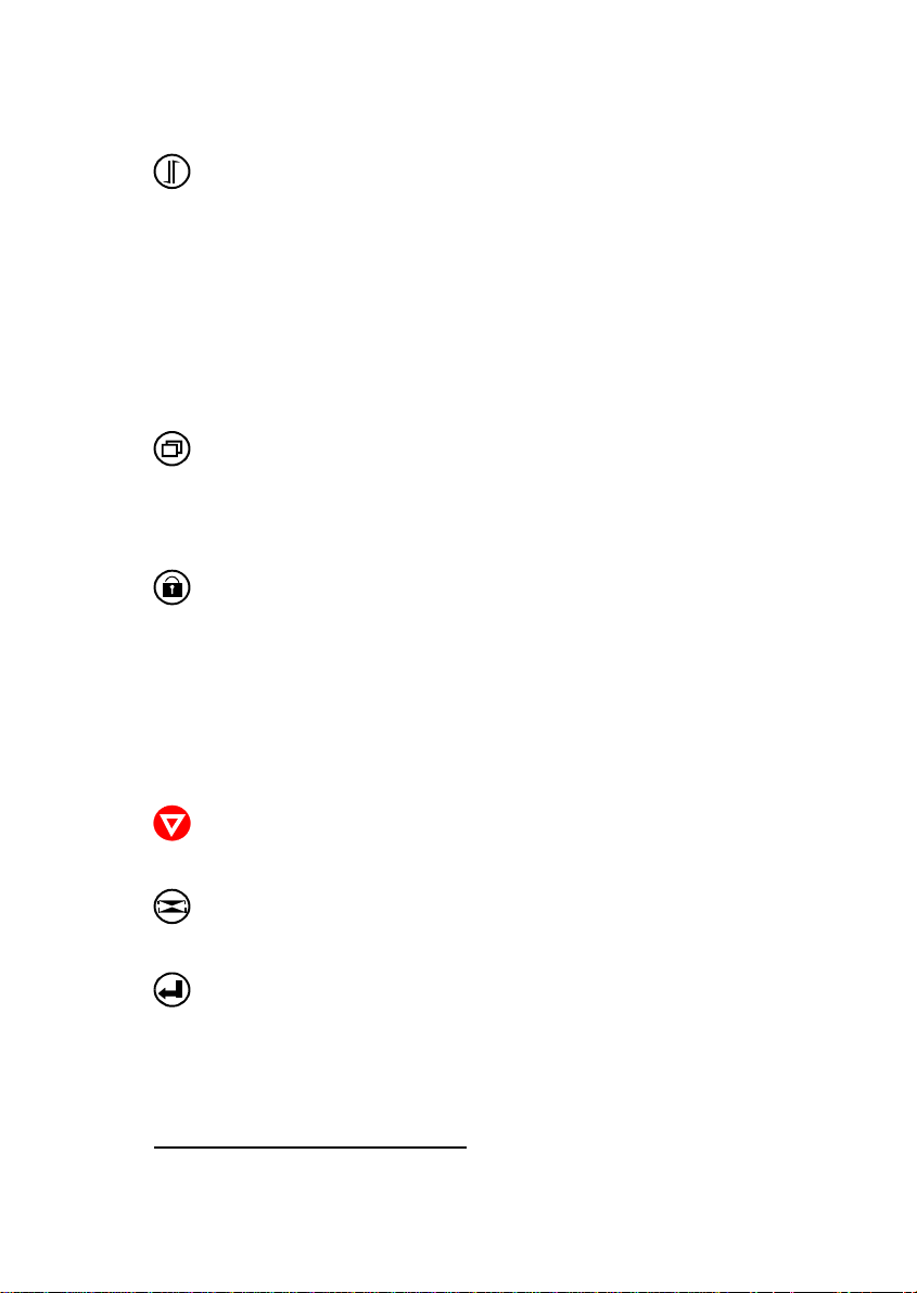
The following keys have only one function:
KEY FUNCTION
[Online / Offline] After pressing this key, the printer enters the
ONLINE or OFFLINE mode.
[Menu] MENU key - to enter the Menu Mode in the first
level.
[Enter] A selection can be confirmed. To cancel the
selection, choose another item and press [ENTER]
again. The selection becomes effective by pressing
the [ONLINE/OFFLINE] key. Behind the actual
displayed parameter appears an asterisk (*).
1
) depends on paper source
2-3
Page 40
Printer Operating
KEY FUNCTION
[Cursor] As soon as the menu mode has been
activated, the four keys can only be used as
cursor keys to move within the menu tree.
Up, Down, Right, and Left Key
2.2.1 READY Mode
In the READY mode only the [Online/Offline] key has a function:
After pressing that key the printer enters the LOCAL mode.
2.2.2 LOCAL Mode
All keys have at least one function. If one key has multiple functions they can
displayed by keeping that key pushed:
Note: The corresponding display messages are shown on page before.
2-4
After pressing that key the printer enters the READY mode
1) Rear cover is locked:
S Short pressing: Unlocking the rear cover.
S Long pressing: Unlocking the rear cover and the print head.
2) Rear cover is unlocked:
S Pressing the key: Locking the rear cover (and the print head).
Page 41
Printer Operating
Single sheet:
S only form feed function. Either the form is fed into print position
or is ejected.
Fanfold Paper:
1) Paper is in Park Position
S paper is fed into print position.
2) Paper is in Print Position
S paper is fed to the tear off position.
S paper is fed into park position.
3) Paper is in Tear Off Position
S printer performs a form feed
S paper is fed into park position (for this function the paper has
to be torn off)
S printer performs a reverse form feed
The four macros are displayed by keeping the key pushed. The
actual macro is displayed first. Release the key as soon as the
desired macro is displayed. This one will be come the active one.
How to confirm and save the selection see chapter 2.4.3 How to
Save Settings.
Press the [Menu] key to activate the menu mode. The four arrows
(up, down, right, and left) can be used as cursor keys to move within
the menu tree. The menu tree is shown and explained on the
page Menu-1.
To leave the menu mode press this key again
With this key a selection will be confirmed. To cancel the selection
choose another item and press [Enter] again. The selection becomes
effective by pressing the [Online/Offline] key.The selection remains
active until the printer is powered off. If the selection should be
available after power off it must be saved by means of the menu
function „SAVE MENU“ see chapter 2.4.3 How to Save Settings.
2-5
Page 42
Printer Operating
2.3 Liquid Crystal Display (LCD)
The LCD indicator gives information about the status of the printer. In general it
can be distinguished between:
S ONLINE messages
S OFFLINE messages
Note: Messages which exceed the 16 character display, e.g. error messages,
are horizontally scrolled.
The green LED lights when the printer is in the ONLINE mode and the display
shows:
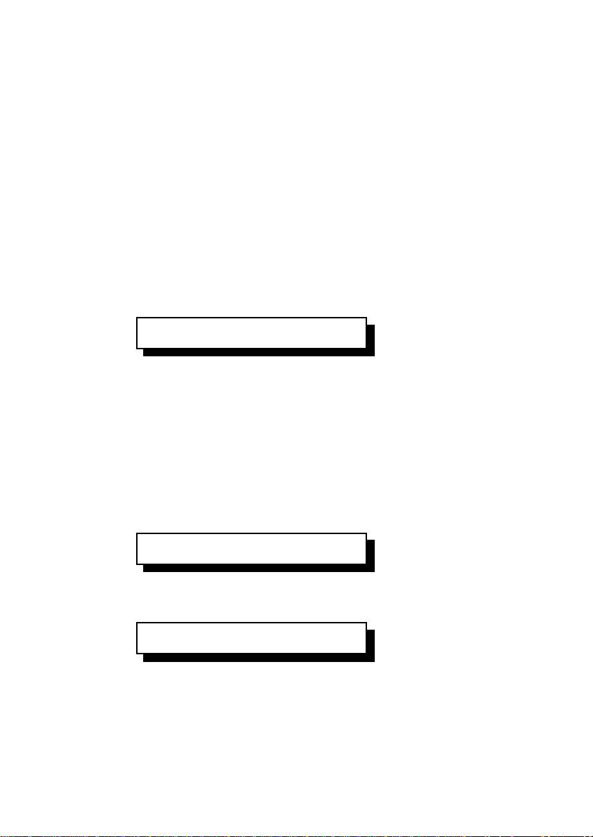
READY 1 ELQ
When the printer is in the OFFLINE mode status information, error messages, or
menu messages are displayed.
Example: The display contents after powering the printer on without a ribbon
cassette.
Because of the error case the printer switches into the Offline Mode.
Switch the printer on. The printer performs an internal test:
TEST
The green LED is flashing and after a short moment the following term is
displayed:
UNLOCKED
Note: In an error case the printer switches into the Offline Mode.
2-6
Page 43
Printer Operating
And then, the message is scrolled:
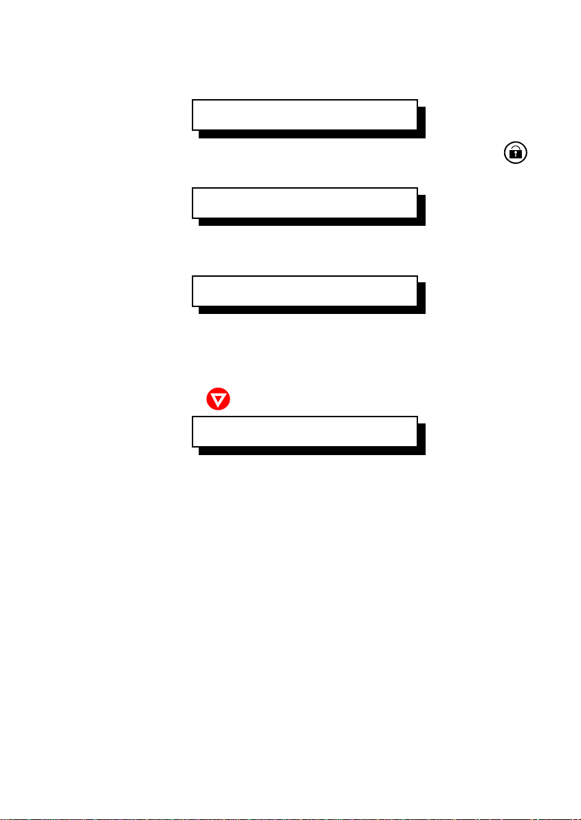
- CHECK RIBBON.....
Insert the ribbon cassette, seechapter 1.6 Ribbon Installation and press .
The display shows:
LOCKING COVER
After the locking procedure the display shows:
LOCKED
In this state it is possible to use all keys.
The printer is still in the OFFLINE Mode due to the previous error condition is
cleared now. Press and the printer switches into the ONLINE Mode.
READY 1 ELQ
2-7
Page 44

Printer Operating
2.4 Menu Mode
All selectable features are accessible via the operator panel and combined in
the printer MENU.
This feature provides:
S easy configuration (language, etc.)
S quick parameter changes
S activation of test functions
There are three entry points:
S TEST MODES (4 test printouts and a Hexdump-function are available)
S DEFINE MACRO (1 of 4 macros can be selected and its contents
defined)
S INSTALLATION (installation specific parameters can be defined)
SAVE MENU is another function at the first level of the menu tree which allows
to save all selections permanently in a non-volatile memory.
The menu is organized in three levels:
S Level 1 Main Functions
S Level 2 Subfunctions
S Level 3 Parameters and values
Level 1 (main functions) is entry point into the menu.
There is only one main function in level 1 without an entry into a lower level,
SAVE MENU.
In Level 2 (subfunctions) menu functions can be activated or a group of values
can be choosen.
In Level 3 (parameters and values at the lowest level) all menu items can be
selected/activated.
2-8
Page 45
Printer Operating
2.4.1 To Activate the Menu
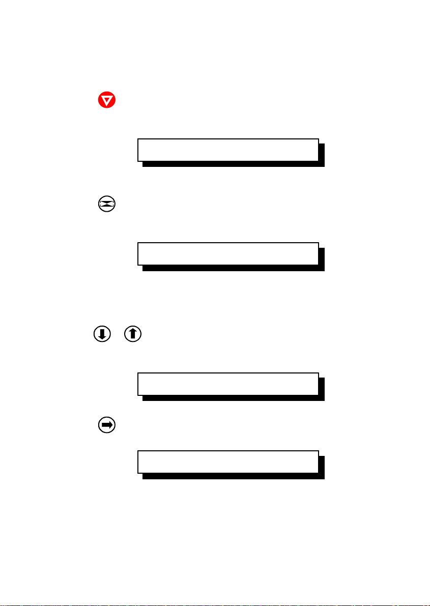
To activate the menu please follow the next steps:
Press :
The printer changes from the READY mode into the LOCAL mode.
The display shows:
LOCAL 1 ELQ
Note: The second term identifies the active macro and the emulation.
Press :
Now, the printer enters the menu mode at the first level of the menu tree.
The display shows:
TEST MODES º
Note: As soon as the menu mode has been activated the arrow keys are
useable as cursor keys to navigate within the menu tree (up, down, right,
and left).
Pres or :
Arrow down or arrow up are used within one level to shift menu functions into
the display. The keys have a wrap around function.
DEFINE MACRO º
Press :
The display shows:
» SELECT MAKRO º
Now, you are at the Subfunction level.
Note: Movement in both directions is possible. Arrow right is used to enter the
next lower level and arrow left is used to enter a higher level.
2-9
Page 46
Printer Operating
Press :
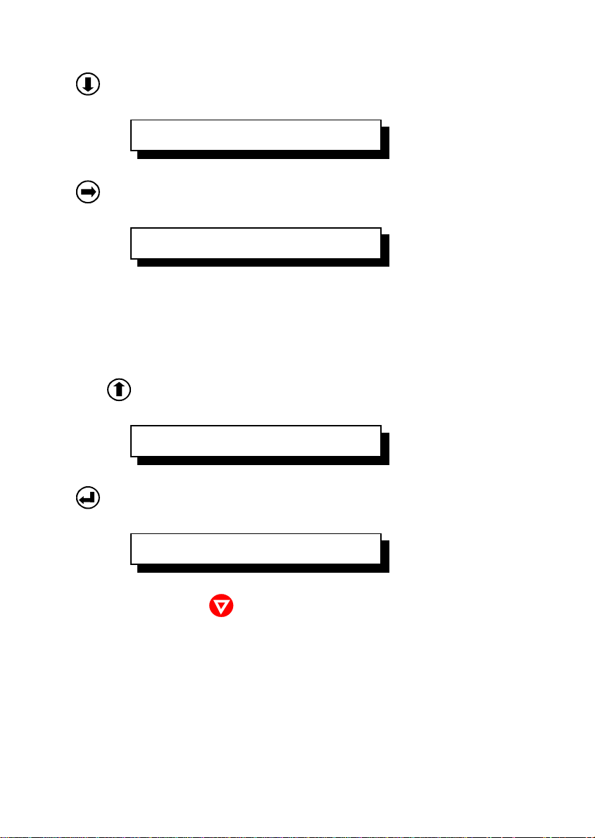
The display shows:
» PAPER SOURCE º
Press :
Now, you are at the third level. The display shows:
» TRACTOR L/U r
The default value for PAPER SOURCE is TRACTOR L/U (lower or upper). At the
lowest level, parameters and values, the asterisk (*) to the right indicates the
actual selection.
To change this parameter into paper source MANUAL,
press twice .
The display shows:
» MANUAL
Press to confirm the choice:
The display shows:
» MANUAL r
To quit the menu mode press .
2-10
Page 47

Printer Operating
2.4.2 To Confirm a Selection
S press ; the confirmed value is marked with an asterisk ( r ) at the last
position as shown in the picture before.
Note: All cursor keys have an autorepeat function.
The menu mode is left either by pressing or by moving to the MAIN
FUNCTION level and then pressing the key.
A number of VALUE settings is summarized in a "Macro". Four macros are
available, each with a different contents of VALUE settings. The standard
emulations are assigned to the macros in following manner:
Macro Emulation
1 Epson LQ ESC/P2
2 IBM Proprinter XL 24E
3 IBM Proprinter XL 24E AGM
4 EPSON LQ ESC/P2
Macro parameters can be tailored to specific application requirements. This
feature is highly beneficial in case of frequent changes between applications in a
multi-user environment. Instead of having to adjust the menu settings every time
before a particular application is started, the user just selects the macro
containing the pre-defined set-up configurations.
2-11
Page 48
Printer Operating
2.4.3 How to Save Settings
The settings selected and confirmed are only active until the printer is switched
off. In order to prevent from losing your new settings you can save them using
the Main Function SAVE MENU.
KEY Display
[OFFLINE] LOCAL 1 ELQ
[MENU] TEST MODES º
[UP] SAVE MENU
[ENTER] SAVING NOW r
(display is flashing)
[ONLINE] READY 1 ELQ
Note: The values of the "current settings" and the macro contents can be
printed using the function PRINT OUT.
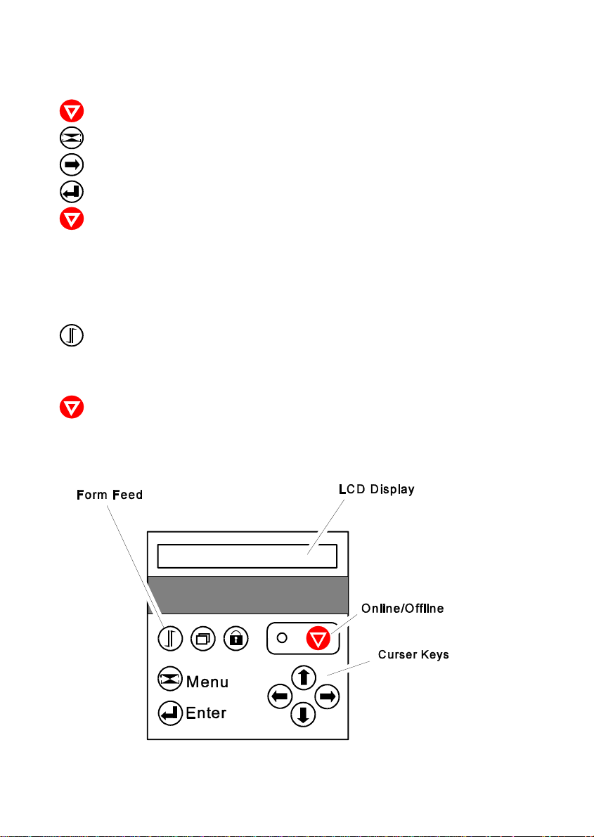
1 LCD Display
2 Online / Offline
3 LED
4 Lock / Unlock Cover
Lock/ Unlock Print Head
5 Macro Selection
6 Form Feed
7 Curser Keys for Navigation
in the Menu Mode
2-12
Page 49

3. Configuring the Printer
3.1 What is Configuring
This chapter describes how to use the operator panel and menu settings to set
up or configure your printer so that the printer and your computer system can
communicate correctly with each other.
Communication between the two requires that both the computer operating system and the printer have the same communication settings or features. The
most important of those are:
S protocol,
S baud rate,
S word length,
S I/F type,
S parity.
You may also need to change some of the printer's other features depending on
your hardware and application requirements, for example:
S paper handling
S text processing.
The MENU mode allows you to access the configuration memory. All settings of
the printer are stored in this memory and can be printed. The possible settings
are discribed in detail on the following pages. A short view of all Menu settings
you will find in chapter 3.5 Menu Item Description, and a detail descriotion in
chapter 4 Explanation of Individual Menu Items.
The standard pameter setting can be printed by using the function PRINT
MENU. The following steps show which keys to use to start this printout.
3-1
Page 50
Configuring the Printer
Key Diyplay
[OFFLINE] LOCAL 1 ELQ
[MENU] TEST MODES º
[RIGHT] » PRINT MENU
[ENTER] » PRINT MENU r
[ONLINE] PRINT MENU r
After feeding paper from the defined paper source the printer starts to print.
When printing is completed the following message will be displayed:
» PRINT MENU
[FORM FEED] PAPER TEAR OFF
(short displayed)
» LOCAL
[ONLINE] READY 1 ELQ
3-2
Page 51

Configuring the Printer
3.2 Standard Configuration
The standard Configuration (factory default values) is reflected in the following
pintout.
PRINT OUT FW-VERSION 20xxxxxx HW-VERSION 29xxxxxx FPGA 4.7 PAGE COUNT 50
INTERFACE
I/F TYPE PARALL./RS232
WORD LENGTH 8 BIT
BAUD-RATE 9600 BIT/S
PARITY BIT EVEN
PROTOCOL DTR
DSR/CTS MODE IGNOR. DSR+CTS
I/F BUFFER 8 KBYTE
MENU ACCESS FULL ACCESS
CURRENT SETTINGS MACRO 1* MACRO 2 MACRO 3 MACRO 4
PAPER SOURCEE TRACTOR LOWER TRACTOR LOWER TRACTOR LOWER TRACTOR LOWER TRACTOR LOWER
PAPER EXIT
PATH BATCH BATCH BATCH BATCH BATCH
BATCH CAPACITY - - - - PRINT POS. ADJ.
TRACT.L. V-POS 0.0 0.0 0.0 0.0 0.0
TRACT.L. H-POS 0.0 0.0 0.0 0.0 0.0
TRACT.U. V-POS 0.0 0.0 0.0 0.0 0.0
TRACT.U. H-POS 0.0 0.0 0.0 0.0 0.0
MANUAL V-POS 0.0 0.0 0.0 0.0 0.0
MANUAL H-POS 0.0 0.0 0.0 0.0 0.0
BIN 1 V-POS 0.0 0.0 0.0 0.0 0.0
BIN 1 H-POS 0.0 0.0 0.0 0.0 0.0
BIN 2 V-POS 0.0 0.0 0.0 0.0 0.0
BIN 2 H-POS 0.0 0.0 0.0 0.0 0.0
BIN 3 V-POS 0.0 0.0 0.0 0.0 0.0
BIN 3 H-POS 0.0 0.0 0.0 0.0 0.0
PAGE LENGTH 72 LINES 72 LINES 72 LINES 72 LINES 72 LINES
FONT QUALITY LQ LQ LQ LQ LQ
GRAPHICS QUALITY STANDARD STANDARD STANDARD STANDARD STANDARD
FONT DATA DATA DATA DATA DATA
PITCH 10 CPI 10 CPI 10 CPI 10 CPI 10 CPI
LINE 6 LPI 6 LPI 6 LPI 6 LPI 6 LPI
EMULATION EPSON LQ EPSON LQ IBM PROPR. IBM PROPR. AGM EPSON LQ
CARACTER SET EPSON EXT. GCT EPSON EXT. GCT IBM SET 2 IBM SET 2 EPSON EXT. GCT
LEFT MARGIN 1. COLUMNS 1. COLUMNS 1. COLUMNS 1. COLUMNS 1. COLUMNS
RIGHT MARGIN 165. COLUMNS 165. COLUMNS 165. COLUMNS 165. COLUMNS 165. COLUMNS
LINE MODE LF=LF, CR=CR LF=LF, CR=CR LF=LF, CR=CR LF=LF, CR=CR LF=LF, CR=CR
PERF. SKIP YES YES YES YES YES
TEAR-OFF-MODE NO NO NO NO NO
1: U.S.A. 1: U.S.A. 1: U.S.A. 1: U.S.A. 1: U.S.A.
Note: An asterisk (’) after MACRO 1 indicates the actual macro
The values after FW- and HW-VERSION indicates the actual release.
All this standard settings of the firmware will be restored with the menu function
RECALL FACTORY.
3-3
Page 52

Configuring the Printer
3.3 Explanation of the printout on the previous page
in the headline behind the term VERSION the revision level of the printer's
firmware can be found.
Then, two columns of hardware related settings follow:
INTERFACE - for communication between the computer operating system and
the printer it is necessary to have the same protocol settings.
S I/F TYPE PARALL./RS232
S WORD LENGTH 8 BIT
S BAUD-RATE 9600 Bps
S PARITY BIT EVEN
S PROTOCOL DTR
S DSR / CTS MODE IGNOR. DSR+CTS
S I/F BUFFER 64 KBYTE
There is no automatic protocol sensing.
The last part of the printout is a list of all MACRO settings.
In this case MACRO 1 is marked with an asterisk (*) which identifies it as the
active macro.
Whenever you make modifications in the active macro without saving them you
will find the new settings under the heading CURRENT SETTINGS. Unless they
are saved, the modifications will stay active only until the printer is switched off.
When the printer is switched on again the macro settings marked with the
asterisk will be reactivated.
3-4
Page 53
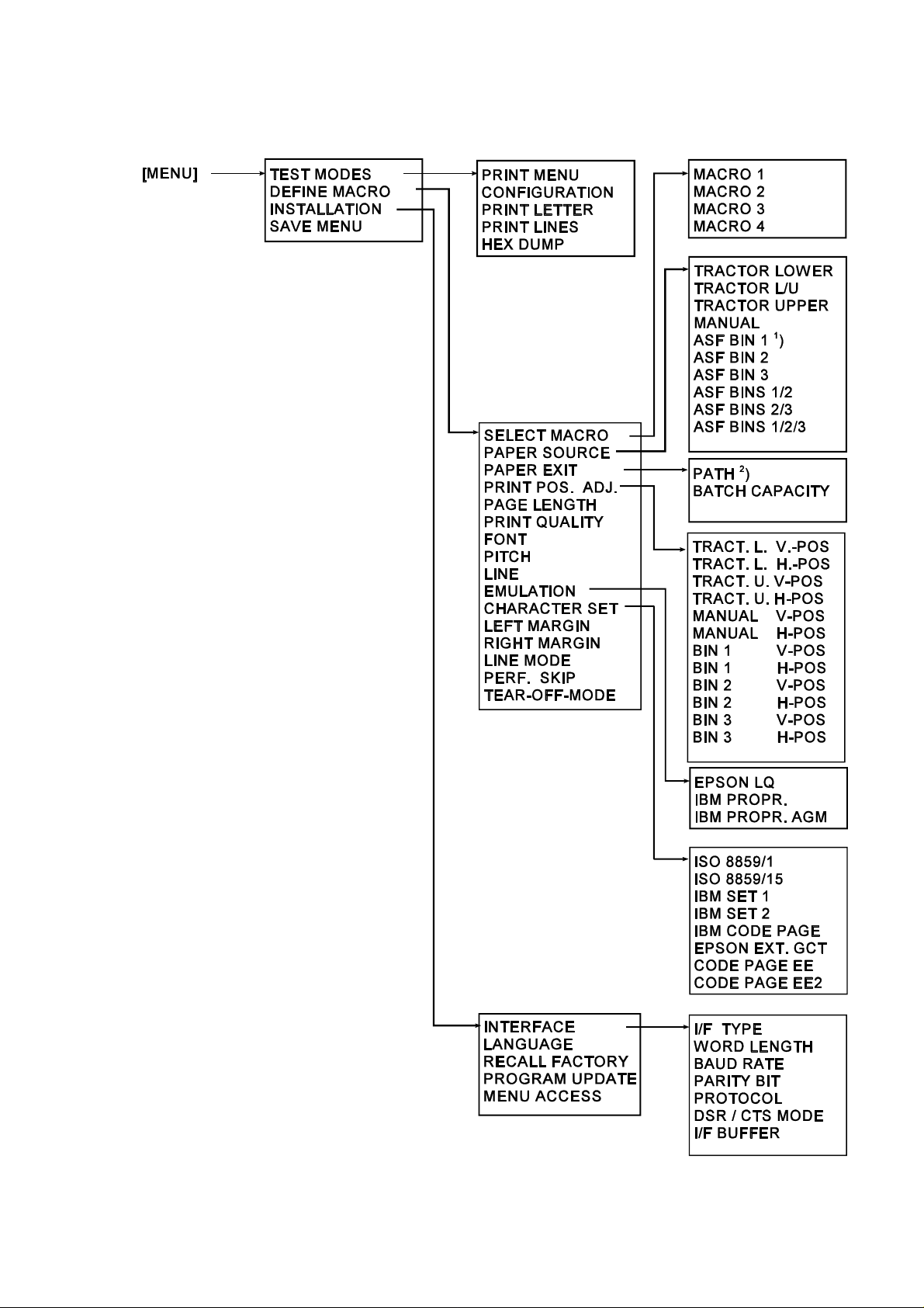
3.4 Menu Tree
1
) The cassette types BIN 1 up to BIN 3 are
only displayed if the ASF cassettes are
installed.
2
) The next level displayed:
BATCH
MANUAL
3-5
3-6
Note: for detail settings of the possible parameters see next tables and the description in chapter 4.
Page 54
Configuring the Printer
3.5 Menu Item Description
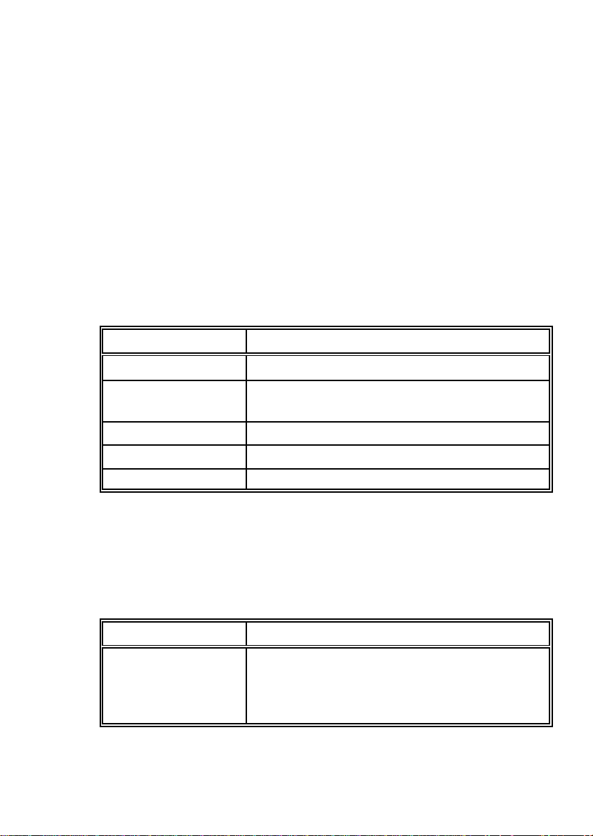
The following tables show menu modes, submenus and parameters.
Precondition is: Access to all menu items is alloved. (MENU ACCESS = ALL)
Otherwise restrictions are to observed.
An asterisk (i) indicates the factory settings. For detail settings see chapter
4 Explanation of Individual Menu Items.
3.5.1Test Modes
Entry Point = TEST MODES
Selection Function
PRINT MENU Printout of the current settings
CONFIGURATION List of all available fonts, the firmware version, and
the page counter value
PRINT LETTER Produces a standard letter (ECMA-132)
PRINT LINES Shows a pattern of all printable characters
HEX DUMP Pintout including all control characters
3.5.2Select Macro
Entry Point = DEFINE MACRO
Selection Value
SELECT MACRO MACRO 1 r
MACRO 2
MACRO 3
MACRO 4
3-7
Page 55
Configuring the Printer
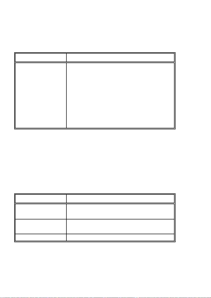
3.5.3 Paper Source
Entry Point = DEFINE MACRO
Selection Parameter
PAPER SOURCE TRACTOR LOWER r
TRACTOR L/U
TRACTOR UPPER
MANUAL
ASF BIN 1 )
1
ASF BIN 2
ASF BIN 3
ASF BINS 1/2
ASF BINS 2/3
ASF BINS 1/2/3
1
) The cassette types ASF BIN 1 up to ASF BIN 3 are only displayed if the ASF
cassettes are installed.
3.5.4 Paper Exit
Entry Point = DEFINE MACRO º PAPER EXIT
Selection Parameter / Value
PATH BATCH r
MANUAL
BATCH CAPACITY BATCH CAP. )
(range: ) ; 20 up to 600; steps = 20)
3-8
Page 56
3.5.5 Print Position Adjustment
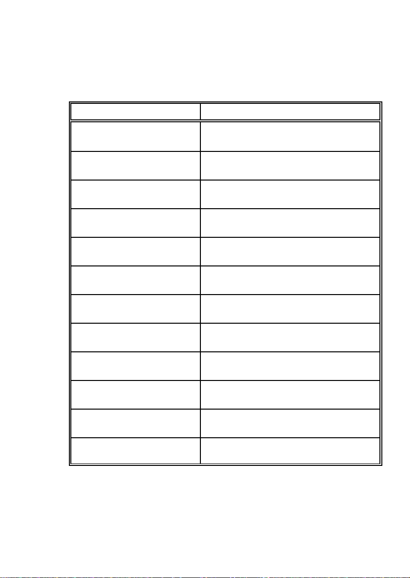
Entry Point = DEFINE MACRO º PRINT POS. ADJ.
Selection Parameter / Value
Configuring the Printer
TRACT.L. V-POS TRACT.L. V. 0.0 r
Tractor Lower Vertical Position (Range: -24.0 up to 99.9; Step: / inch)
1
6
TRACT.L. H-POS TRACT.L. H. 0.0 r
Tractor Lower Horizontal Position (Range: -6.0 up to 6.0; Step: / inch)
1
10
TRACT.U.V-POS TRAKT.U. V. 0.0 r
Tractor Upper Vertical Position (Range: -24.0 up to 99.9; Step: / inch)
1
6
TRACT.U.H-POS TRACT.U. H. 0.0 r
Tractor Upper Horizontal Position (Range: -6.0 up to 6.0; Step: / inch)
1
10
MANUAL V-POS. MANUAL V. 0.0 r
Manual Vertical Position (Range: -1.5 up to 24.0; Step: / inch)
1
6
MANUAL H-POS. MANUAL H. 0.0 r
Manual Horizontal Position (Range: -6.0 up to 6.0; Step: / inch)
1
10
BIN 1 V-POS. BIN 1 V. 0.0 r
Bin 1 Vertical Position (Range: -1.5 up to 24.0; Step: / inch)
1
6
BIN 1 H-POS. BIN 1 H. 0.0 r
Bin 1 Horizontal Position (Range: -6.0 up to 6.0; Step: / inch)
1
10
BIN 2 V-POS. BIN 2 V. 0.0 r
Bin 2 Vertical Position (Range: -1.5 up to 24.0; Step: / inch)
1
6
BIN 2 H-POS. BIN 2 H. 0.0 r
Bin 2 Horizontal Position (Range: -6.0 up to 6.0; Step: / inch)
1
10
BIN 3 V-POS. BIN 3 V. 0.0 r
Bin 3 Vertical Position (Range: -1.5 up to 24.0; Step: / inch)
1
6
BIN 3 H-POS. BIN 3 H. 0.0 r
Bin 3 Horizontal Position (Range: -6.0 up to 6.0; Step: / inch)
1
10
3-9
Page 57
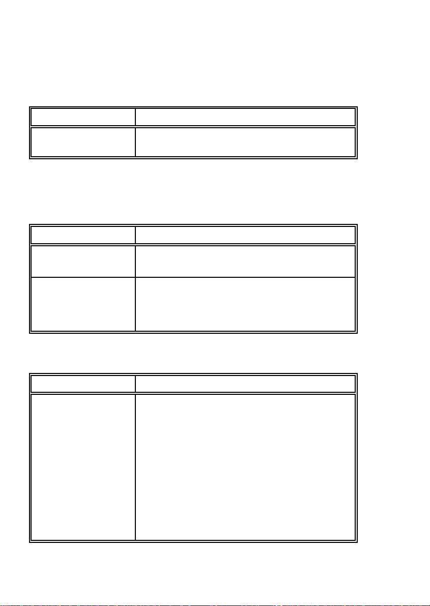
Configuring the Printer
3.5.6 Page Length
Entry Point = DEFINE MACRO
Selection Value
PAGE LENGTH 72 Lines r
(Range: 1 up to 144 Zeilen)
3.5.7 Print Quality
Entry Point = DEFINE MACRO º PRINT QUALITY
Selection Parameter
FONT QUALITY LQ / NLQ
(DRAFT for font DATA)
GRAPHICS QUAL. STANDARD r
WIN.LQ 180 DPI
WIN.NLQ 90 DPI
WI.DRAFT 60 DPI
3.5.8 Font
Entry Point = DEFINE MACRO
Selection Parameter
FONT DATA r
ROMAN LQ / NLQ
SANS SERIF LQ / NLQ
COURIER LQ / NLQ
PRESTIGE LQ / NLQ
SCRIPT LQ / NLQ
OCR B LQ
OCR A LQ
ORATOR-C LQ / NLQ
ORATOR LQ / NLQ
DATA LARGE
3-10
Page 58
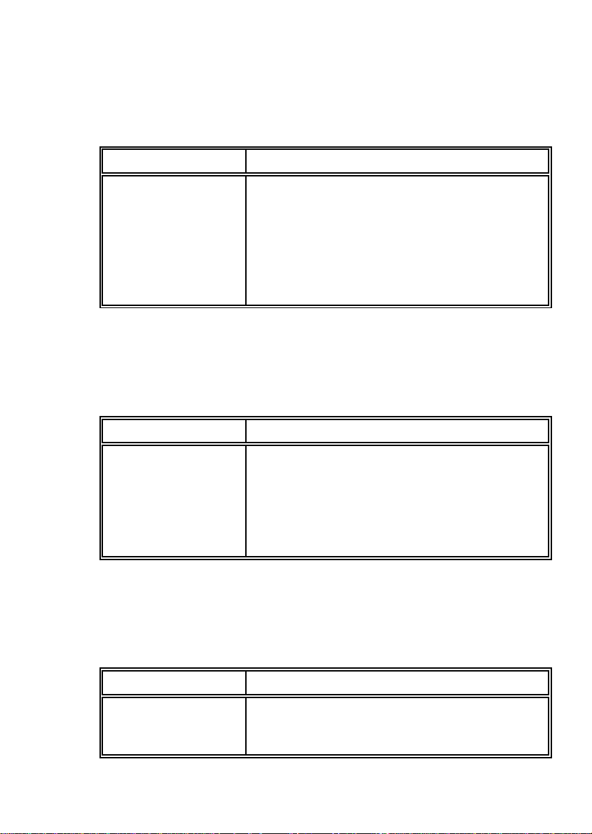
3.5.9 Pitch
Entry Point = DEFINE MACRO
Selection Value
PITCH 10 CPI r
12 CPI
15 CPI
17 CPI
18 CPI
20 CPI
PROPORTIONAL
3.5.10 Line
Entry Point = DEFINE MACRO
Selection Value
Configuring the Printer
LINE 2 LPI r
3 LPI
4 LPI
6 LPI
8 LPI
12 LPI
3.5.11 EMULATION
Entry Point = DEFINE MACRO
Selection Value
EMULATION EPSON LQ r
IBM PROPR.
IBM PROPR. AGM
3-11
Page 59
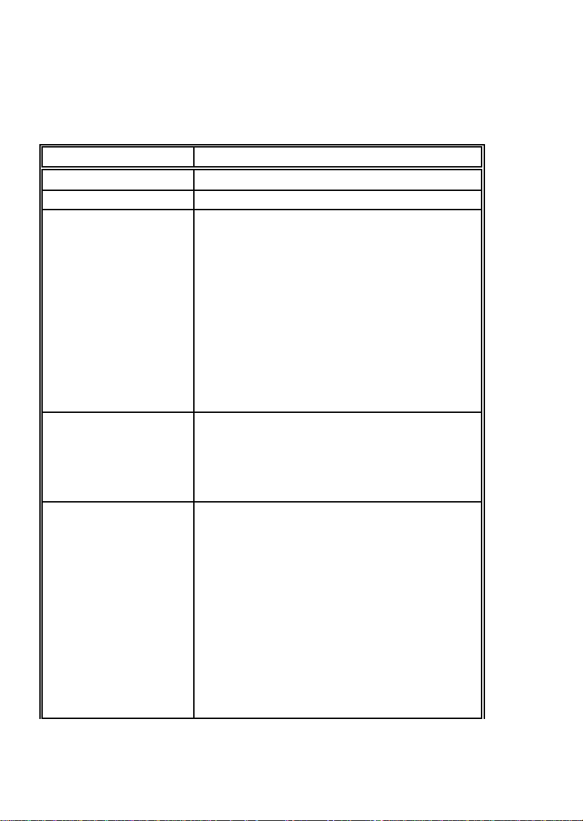
Configuring the Printer
3.5.12 Character Set
Entry Point = DEFINE MACRO º CHARACTER SET
Selection Value/ Parameter
ISO 8859/1
ISO 8859/15
IBM SET 1 / IBM SET 2 1: U.S.A. r
2: FRANCE
3: GERMANY
4: U.K.
5: DENMARK
6: SWEDEN
7: ITALY
8: SPAIN
9: JAPAIN
10: NORWAY
11: DENMARK 2
12: SPAIN 2
13: LATIN AM.
14: TURKEY
IBM CODE PAGE 1: PAGE 437 r
2: PAGE 850
3: PAGE 860
4: PAGE 863
5: PAGE 865
6: PAGE 858
EPSON EXT. GCT 1: U.S.A. r
2: FRANCE
3: GERMANY
4: U.K.
5: DENMARK
6: SWEDEN
7: ITALY
8: SPAIN
9: JAPAIN
10: NORWAY
11: DENMARK 2
12: SPAIN 2
13: LATIN AM.
14: TURKEY
15: LEGAL
3-12
Page 60
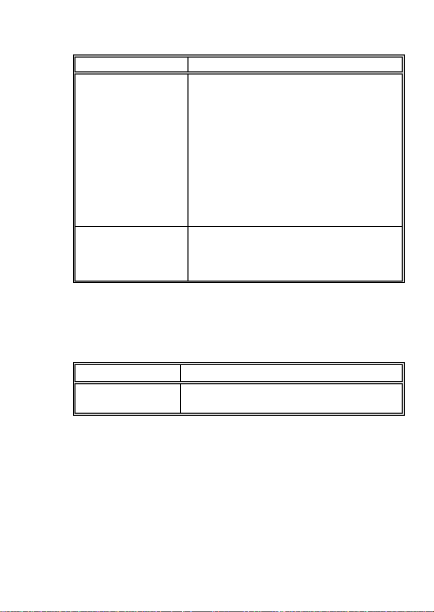
Selection Value/ Parameter
CODE PAGE EE 1: CP 437 GK
2: CP 851 GK
3: CP 928 GK
4: CP 855 CYRI
5: CP 866
6: CP 869
7: CP 852
8: KAMENICKY
9: ISO LATIN 2
10: MAZOVIA
11: CP 437 HUN
12: CP 852 SEE
13: CP 866 LAT
14: CP WIN LAT2
CODE PAGE EE2 1: CP 771
2: CP 773
3: CP 774
4: CP 775
5: BALTIC RIM
3.5.13 Left Margin
Configuring the Printer
Entry Point = DEFINE MACRO
Selection Value
LEFT MARGIN 1. POSITION r
(Range: 1 up to 16; Step / inch)
1
10
3-13
Page 61
Configuring the Printer
3.5.14 Right Margin
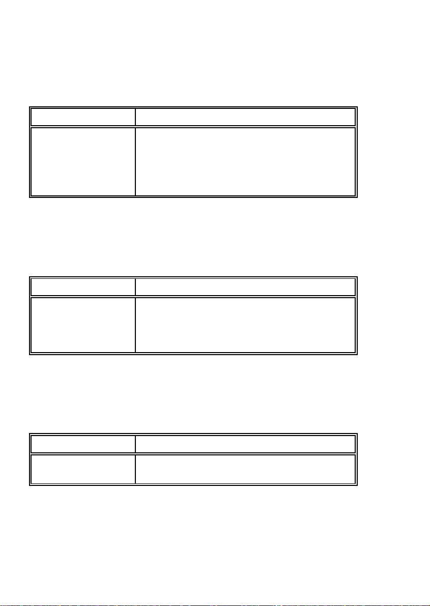
Entry Point = DEFINE MACRO
Selection Value
RIGHT MARGIN 136. POSITION r
165. POSITION
80. POSITION
132. POSITION
(measuring unit / inch))
1
10
3.5.15 Line Mode
Entry Point = DEFINE MACRO
Selection Value
LINE MODE LF = LF, CR = CR r
LF = LF + CR
CR = LF+CR
LF, CR = LF + CR
3.5.16 Perforation Skip
Entry Point = DEFINE MACRO
Selection Parameter
PERF. SKIP YES r
NO
3-14
Page 62
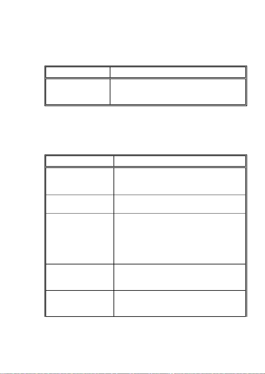
3.5.17 Tear Off Mode
Entry Point = DEFINE MACRO
Selection Wert / Parameter
TEAR-OFF-MODE NO r
TEAR-OFF 10 S.
TEAR-OFF 1 S.
3.5.18 Interface
Entry Point = INSTALLATION º INTERFACE
Selection Parameter / Value
I/F TYPE PARALL. / RS232 r
PARALL. / RS422
PARALLEL
WORD LENGTH ) 7 BIT r
1
8 BIT
BAUD-RATE ) 1200 BPS r
1
2400 BPS
4800 BPS
9600 BPS
19200 BPS
38400 BPS
PARITY BIT EVEN r
ODD
NONE
PROTOCOL DTR r
XON / XOFF
XON / XOFF + DTR
Configuring the Printer
3-15
Page 63
Configuring the Printer
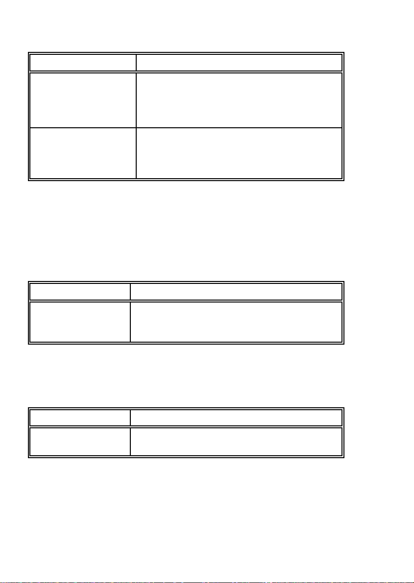
Selection Parameter / Value
DSR / CTS MODE IGNOR. DSR+CTS r
DSR+CTS ACTIVE
CTS ACTIVE
DSR ACTIVE
BUFFER 64 KBYTE r
32 KBYTE
8 KBYTE
1 KBYTE
1
) Only indicated if the serial (RS232 or RS422) interface is selected.
3.5.19 Language
Entry Point = INSTALLATION
Selection VALUE
LANGUAGE ENGLISH r
DEUTSCH
FRANCAIS
3.5.20 Recall Factory
Entry Point = INSTALLATION
Selection Function
RECALL FACTORY All standard default settings of the firmware will be
restored but not saved.
3-16
Page 64
Configuring the Printer
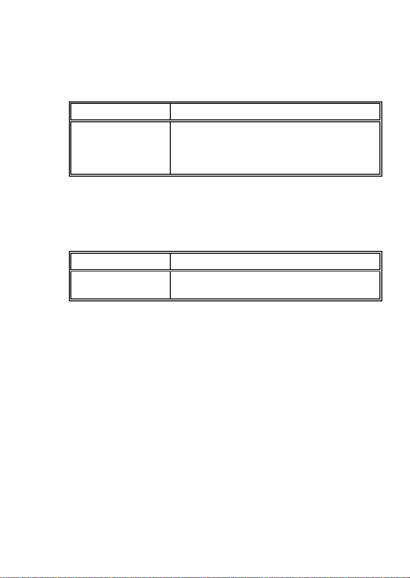
3.5.21 Program Update
Entry Point = INSTALLATION
Selection Function
PROGRAM UPDATE A new firmware version can be down loaded from
the host system via the interface cable. All
parameters will be reset to their factory default
value.
3.5.22 Menu Access
Entry Point = INSTALLATION
Selection Parameter
MENU ACCESS FULL ACCESS r
NO ACCESS
3-17
Page 65

4. Description of the Individual Menu Items
Main Functions and Entry Points into the menu
The following Main Functions are available:
S TEST MODES
There are 4 test printouts and the hexdump function available. (For detail
information see chapter 4.1 beginning on the next page).
S DEFINE MACRO
Behind this menu point there are all functions and parameters to define a
macro. (For detail information see chapter 4.2).
S INSTALLATION
In the first Sub Function named INTERFACE you can manipulate parameters
to enable communication with the host. (See Chapter 4.3).
S SAVE MENU
Any desired changes to the default settings can be saved here. After power
on the new settings are activated.
While this function is operating the display flashes SAVING NOW.
4-1
Page 66

Description of the Individual Menu Items
4.1 TEST MODES
S PRINT MENU
This test printout shows the current settings of all parameters and the
contents of the macros. This printout is helpful for future reference and when
macros are to be changed. For detail see chapter 3.2 Standard
Configuration.
S CONFIGURATION
This test printout lists all available fonts, contains the page count to identify
the actual number of printed pages, and gives information on technical
releases which are intended for service purposes. A sample you will find in
chapter 1.9 PRINT MENU.
S PRINT LETTER
This test printout produces a standard letter (ECMA-132) which can be used
for measuring the printer's throughput. See a sample in chapter 1.9 PRINT
MENU.
S PRINT LINES
Tis test printout shows a pattern of all printable characters. Use this to check
if the printer operates correctly. See a sample in chapter 1.9 PRINT MENU.
S HEX DUMP
This function allows to analyze that the data received by the printer. Control
codes are no longer carried out, instead all data is printed in hexadecimal
format and as ASCII characters. Any non-printable characters, such as
carriage return are only represented as a single dot (.) in the ASCII list.
It may happen that the transmission of data to the printer will be interrupted
during Hex Dump. In this case, printing of data received after the break is
started on the next available line. The result is an irregular right margin which
is not an indicator for any loss of data.
4-2
Page 67

Description of the Individual Menu Items
4.2 DEFINE MACRO
S SELECT MACRO
To select one of the four macros which can be used for quickly changing the
printer settings for different applications. For example: Application A needs
fanfold paper with a top margin of one, application B processes fanfold paper
in a batch with a top margin of six. Simply by pressing Macro Selection key
the macro containing the information for the specific application
requirements can be activated.
S PAPER SORCE
The printer offers three choices for paper source:
S TRACTORT (fanfold paper)
S MANUAL (single sheet)
S ASF CASSETTES (optional)
They can be accessed either individually or bundled in a pool. Any
combination of cassettes can be selected.
Note: Please refer to chapter 8 Technical Data, for detailed media
specifications.
S PAPER EXIT
It is possible to define PATH and BATCH CAPACITY. The desired paper exit
can be selected via operator panel or software.
S Parameters of PATH
BATCH (default) and MANUAL are selectable.
MANUAL is for single sheet only with output to the front.
S Values for BATCH CAPACITY are in the range from ) (for no setting =
default); and 20 up to 600 in steps of 20.
4-3
Page 68

Description of the Individual Menu Items
S PRINT POS. ADJ.
This function adjusts the print position in the current macro for the six
different paper paths TRACT. L.V-POS, TRACT. L.H-POS,
TRACT.U.V-POS, TRACT. U.H-POS, MANUAL V-POS, MANUAL H-POS or
ASF BIN x V-POS, ASF BIN x H-POS (x = 1 up to 3) to exactly position the
printout in relation to the top edge of the form in use. It is meant to be a
corrective parameter to compensate variations in paper size and pre-printed
material.
This parameter covers a range of:
S fanfold vertical: -24.0 up to 99.9 in steps of / inch,
S fanfold horizontal: - 6.0 up to 6.0 in steps of / inch
S manual or bins vertical: - 1.5 up to 24.0 in steps of / inch,
S manual or bins horizontal: - 6.0 up to 6.0 in steps of / inch
1
6
1
10
1
6
1
10
where "-" is up the page and "+" is further down the page.
Caution: The set up of PRINT.POS.ADJ. will become effective on the next
page of the form. Therefore, it is recommended to define
PRINT.POS.ADJ. as long as the paper is in the park position and
before starting the print job.
S PAGE LENGTH
Page length is expressed in terms of lines within the range of 1 to 144 lines.
Any page length setting is based on six lines per inch, regardless of the
number of lines per inch selected in the line setting or defined by the
application.
The following table shows the number of lines for the most common paper
sizes:
Paper length in inches Appropriate setting in no. of lines
4 24
1
4 / 25
6
6 36
8 48
1
8 / 51
2
11 66
2
11 / 70
3
12 (default setting) 72
The page length setting is the basis from which perforation skip, TEAR-OFF
and margins are calculated.
An incorrect page length, therefore, leads to an incorrect perforation skip.
4-4
Page 69

Description of the Individual Menu Items
S PRINT QUALITY
Is splitted up into:
S Font Quality
Four different font quality levels can be selected:
S High Speed Draft (font "Data")
S Draft quality (font "Data")
S Near letter quality (NLQ displayed with the font name)
S Letter quality (LQ displayed with the font name).
and
S Graphics Quality
Four different graphics quality levels can be selected:
S Standard
S Win. LQ 180 DPI
S Win. NLQ 90 DPI
S WI. Draft 60 DPI
Different print qualities result in different print speed.
S FONT
A font is a family of characters with the same style and size. The appearance
of the font can be varied by using attributes such as: size, bold, italic, etc.
The fonts included in the PM are:
S Data ) Roman
S Sans Serif ) Courier
S Prestige ) Script
S OCR B ) OCR A
S Orator-C ) Orator
S DATA LARGE
see Appendix B for print samples.
Note: The printtest CONFIGURATION lists all available fonts. The firmware of
the printer comprises also barcodes. Detail information for printing barcodes can be found in Appendix F Barcodes Quick Reference.
4-5
Page 70

Description of the Individual Menu Items
S Pitch
Defines the number of characters printed per inch (10, 12, 15, 17, 18, 20 or
proportional).
Any pitch setting can be combined with any available font. In some cases
this might lead to a conflict with font designs. The pitch setting is, therefore, a
matter of personal taste.
S LINE
Determines the number of lines per inch (line space).
S EMULATION
The emulation determines the set of commands available for the printer (see
Appendix D and E). You can activate the following emulations:
S EPSON LQ / ESC/P2
S IBM PROPR.
S IBM PROPR. AGM
The selected emulation is also part of the actual macro. With a change of the
macro (e.g. key is pressed) it may happen that the emulation will also
be changed.
Be careful: Do not change the emulation within an application.
.
S CHARACTER SET
When selecting a character set it can be further specified by the corresponding national versions.
Detailed print samples are found in Appendix B and the Character Set
Tables in Appendix C.
If a different macro is selected the default character set may change as well.
e.g. S IBM PROPR. emulation has the character set IBM SET 2 as
default.
S EPSON / EDC/P2 emulation has the character set EPSON
EXT.GCT as default.
4-6
Page 71
Description of the Individual Menu Items
S LEFT MARGIN
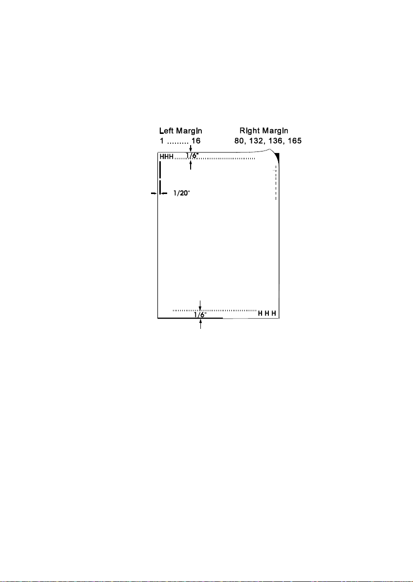
The left margin is set in 1/10" steps, depending on the actual selection. The
first left margin position is 1/20" from the left edge of the paper which means
that the letter H in regular "Data" font would be positioned 1/20" from the left
edge of the paper. The left margin can be set to a maximum of 16/10".
S RIGHT MARGIN
The right margin is set to print position 80, 132, 136, or 165, always
measured from the position of the first possible, not actual, left margin
setting.
S LINE MODE
S If LF = LF + CR is selected the printer performs a line feed and
additionally a carriage return (CR) for every line feed (LF) received via
the interface.
S If CR = LF + CR is selected the printer performs a carriage return an
additionally a line feed (LF) for every carriage return (CR) received via
the interface.
4-7
Page 72

Description of the Individual Menu Items
S PERF. SKIP
If PERF. SKIP is set to YES the printer starts to print after the specified top
margin and stops printing before the bottom margin.
If PERF. SKIP is set to NO the printer ignores top and bottom margin and
prints from the very first to the very last line. That means that on a standard
11" paper 66 lines are available for printing.
S TEAR-OFF-MODE
There are three possible settings within this mode:
S NO
S TEAR-OFF 10 S.
S TEAR-OFF 1 S.
When TEAR-OFF is selected the printer waits for one or ten seconds and,
unless further data are received, advances the paper to the first perforation
behind the text.
Regardless of this setting, whenever a change from fanfold to another paper
source occurs the printer will request the fanfold paper to be torn off before
the paper is moved into the park position.
4-8
Page 73

Description of the Individual Menu Items
4.3 INSTALLATION
S INTERFACE
S I/F TYPE (Interface Type)
The following types are available:
S PARALLEL / RS232
S PARALLEL / RS422
S PARALLEL
In case the PARALLEL / RS232 or PARALLEL / RS422 interface type is
selected the printer switches automatically between the parallel and
serial interface. The first data received at the port determine which
interface port becomes active. The other interface port will be closed so
that only one interface is active at a time (for detailed information see
Appendix A Interface Description).
The factory setting for the interface type are: PARALL./RS232, 8 bit word
length, 9600 baud rate, even parity bit, DTR protocol, ignore DSR+CTS,
and 8 Kbyte Buffer.
S WORD LENGTH
Number of bits that represent a word; values are 7 or 8 bit
S BAUD RATE (Only indicated if the serial interface is selected)
Controls the speed of data transfer. Possible transfer rates are: 600,
1200, 2400, 4800, 9600, 19200 or 38400 bps.
S PARITY BIT (Only indicated if the serial interface is selected)
The data transfer will be checked by an even or odd parity bit. The values
are: EVEN, ODD, or NONE.
S PROTOCOL (Only indicated if the serial interface is selected)
Selectable are: DTR, XON/XOFF, or XON/XOFF+DTR.
4-9
Page 74

Description of the Individual Menu Items
S DSR/CTS MODE (Only indicated if the serial interface is selected)
Selectable are: IGNORE DSR+CTS, DSR+CTS ACTIVE, CTS ACTIVE,
or DSR ACTIVE.
S I/F BUFFER
Buffer size in Kbyte. The maximum (factory setting) size is 64 Kbyte.
S LANGUAGE
The operator panel may display its messages in three languages. Select one
out of the following: ENGLISH, DEUTSCH, or FRANCAIS.
S RECALL FACTORY
All standard default settings of the firmware will be restored. The contents of
Page Counter and the Paper-in Adjust will not be changed. Use the function
SAVE MENU if the standard settings shall be stored permanently.
S PROGRAM UPDATE
A new firmware version can be down loaded from the host system via the
interface cable. All parameters will be reset to their factory default value.
S MENU ACCESS
There are two possibilities to define the user’s access rights to the menu.
S FULL ACCESS All functions can be used (default)
S NO ACCESS The menu is not accessible at all. Only the menu item
TEST MODES is available.
Note: It is the system manager’s responsibility to grant access to the menu
when NO ACCESS was selected.
4-10
Page 75

5. Maintenance
Prefered Material
The following materials and cleaning lubricants are recommended whem
maintaining thr printer:
S Lint-free cloth
S Vacuum cleaner.
5.1 Cleaning Surrounding Areas
The user should clean the printer every six months or after 50,000 prints,
whatever occurs first. If you experience paper feed problems or if the print head
carriage movement is hampered, cleaning should be carried out more often.
Note: The Page Counter (PGCNT) in the PRINT MENU will inform about the
actual number of printed pages (see illustration on the next page) .
5-1
Page 76
Maintenance
PRINT MENU
CONFIGURATION FW-VERSION 202xxxxxPAGE COUNT 126
C031 ISO 8859/1 CO32 ISO 8859/15 C061 IBM SET 1
C062 IBM SET 2 C063 IBM CODE PAGE C071 EPSON EXT. GCT
C100 CODE PAGE EE C101 CODE PAGE EE2
DATA ROMAN NLQ ROMAN LQ
SANS SERIF NLQ SANS SERIF LQ COURIER NLQ
COURIER LQ PRESTIGE NLQ PRESTIGE LQ
SCRIPT NLQ SCRIPT NQ OCR B LQ
OCR A LQ ORATOR-C NLQ ORATOR-C LQ
ORATOR NLQ ORATOR LQ DATA LARGE LQ
ZEICHENSATZ : EPSON EXT. GCT 1: U.S.A.
PRINTHEAD NEEDLE
1 2 3 4 5 6 7 8 9 10 11 12 13 14 15 16 17 18 19 20 21 22 23 24
DATA DRAFT
$ !"#$%&'()*+,-./01234567890:;<=>?@ABCDEF.......
.
.
Note: FW-VERSION indicates the revision level of the firmware.
5-2
Page 77
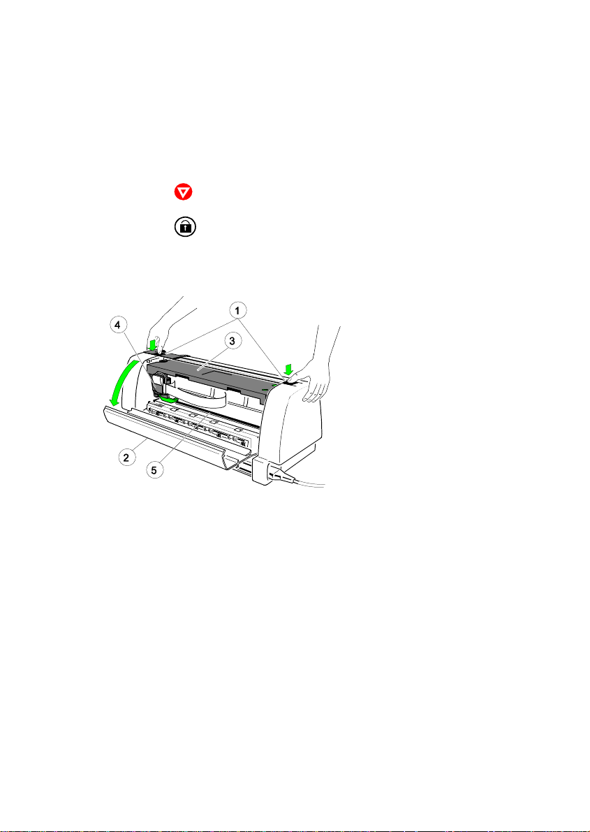
5.2 Cleaning Procedure
S Power the printer ON:
S To open the rear of the printer :
S Press to change into the LOCAL mode.
S Press until UNLOCKED is displayed.
S Press the left and right unlocking buttons (1) simultaneously and open
the rear cover (2).
1 Locking Buttons
2 Rear Cover
3 Ribbon Cassette
4 Print Head (in park position)
5 Print Bar
Maintenance
S Remove the ribbon cassette.
S Thoroughly brush and vacuum all accessible areas to remove any paper
particles and dust.
5-3
Page 78
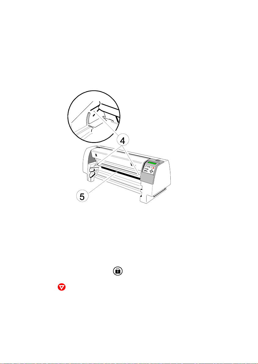
Maintenance
S Open the front cover of the printer:
S Remove the Manual Sheet Feeder, Tractor Cassettes, and the Paper
Insertion Guide.
S Press the left and right plastic leads (4) and open the front cover (5).
S Clean the paper pressure rollers and the transport rollers.
S Clean the covers and the operator panel with a damp, lint-free cloth. Do
not use cleaning solvents or excessive amounts of water.
S Insert the ribbon cassette (see chapter 1.6 Ribbon Installing).
S Close the front cover and press until LOCKED is displayed.
S Pressing causes the printer to enter the READY mode.
5-4
Page 79
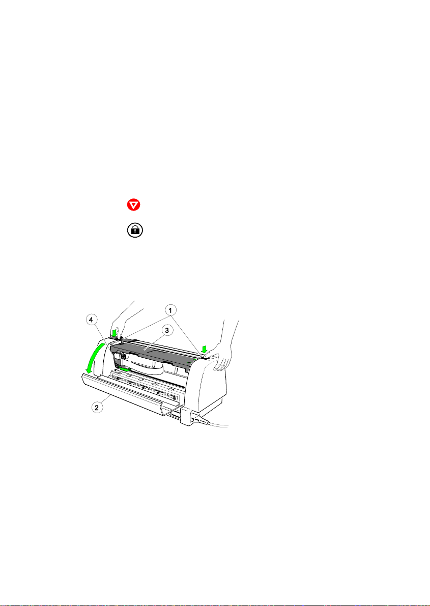
Maintenance
5.3 User Replaceable Parts
The print head has an expected life time of approximately 600 Mio.
characters.
5.3.1 Print Head Exchange
Note: The print head may be very hot immediately after printing.
S Power the printer ON:
S To open the rear of the printer :
S Press to change into the LOCAL mode.
S Press until UNLOCK COVER / PH is displayed. Now the rear cover
and the print head are unlocked. (PH means print head).
S Release the rear cover (2) by pressing simultaneously the two
lockingbuttons (1) and swivel the rear cover backwards.
1 Locking Buttons
2 Rear Cover
3 Ribbon Cassette
4 Print Head (in park position)
S Slide out the Ribbon cassette (3) to the rear.
S Power the printer OFF.
5-5
Page 80
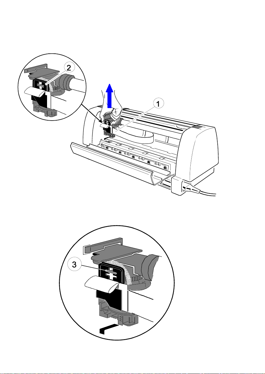
Maintenance
S Disconnect the print head cable (4) carefully by pullingblack the plastic
holder (5) upwards.
S The loose print head cable remains on the plastic holder (5a).
5-6
Page 81
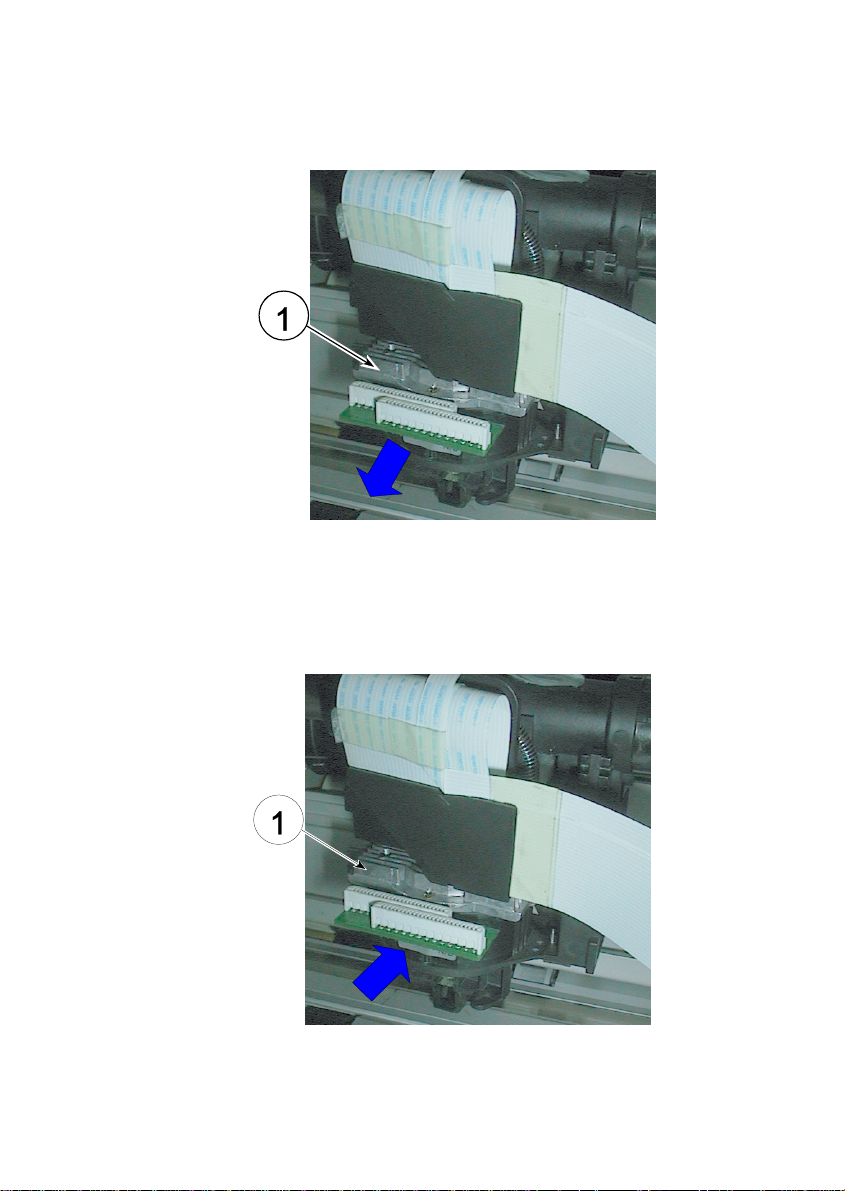
S Slide the print head (6) out of the fixation support.
5.3.2 Installation procedure:
S Put the new print head (6) into its fixation support and slide it in.
Maintenance
5-7
Page 82
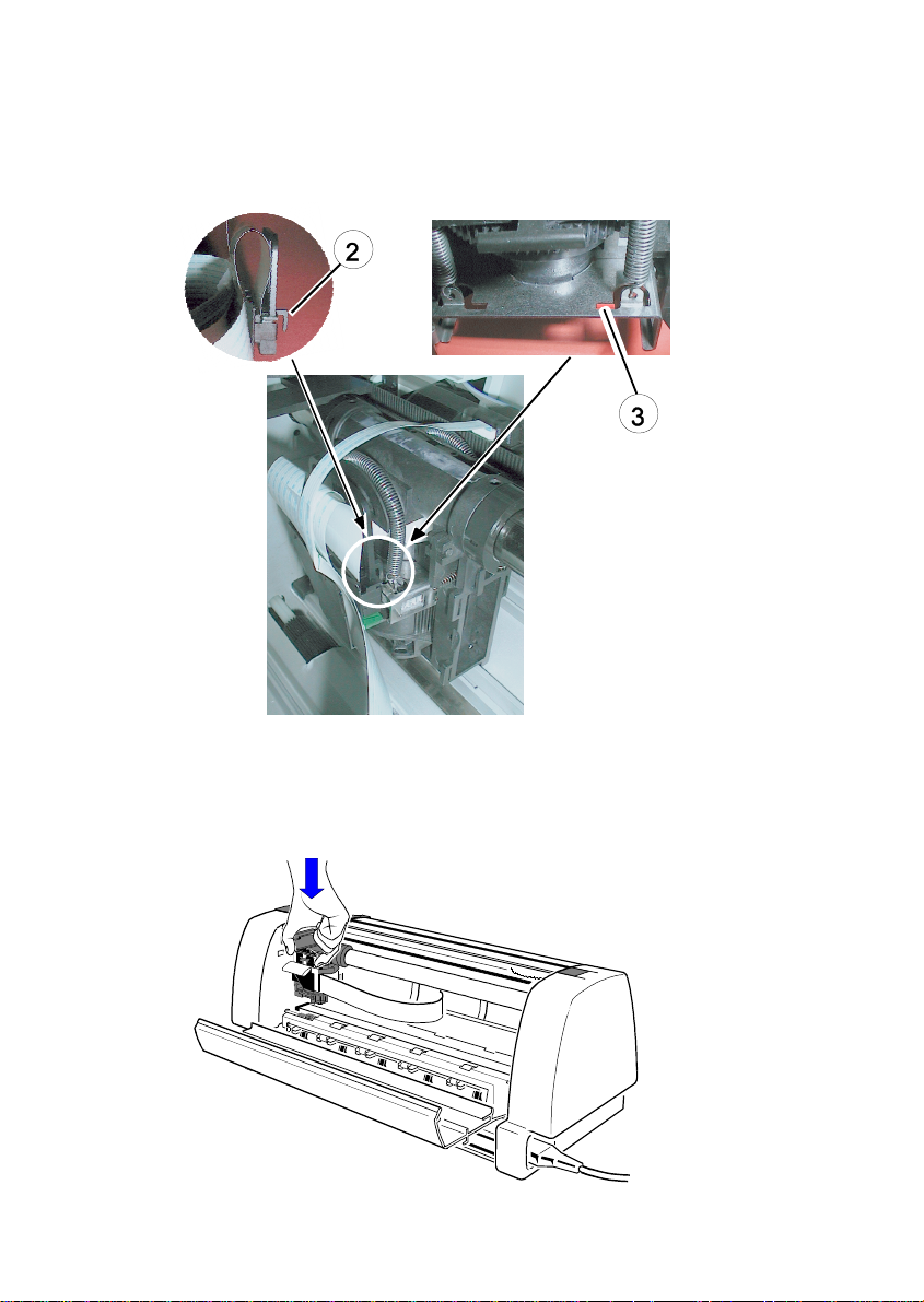
Maintenance
S Put the plastic pin (7) into the hole (8) of the carriage for adjusting the
print head cable.
S After finding the right position connect the print head cable by pressing
the plastic holder down (with strong pressure).
5-8
Page 83
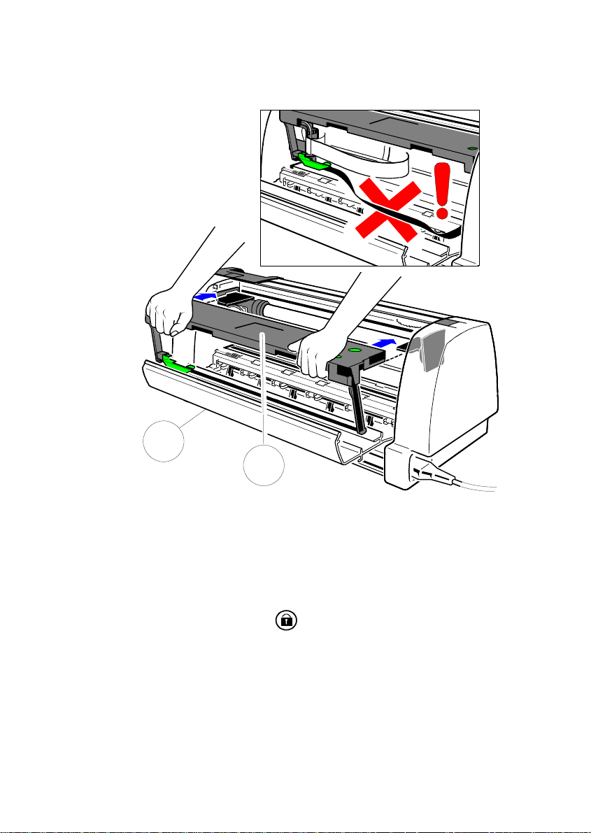
Maintenance
S Insert the ribbon cassette (3) and close the rear cover (2) of the printer.
2
1
S Power the printer ON.
S The LED is flashing and the display shows:
UNLOCK ( CHECK RIBBON... ).
S Lock cover by pressing key . The print head will be locked
automatically.
S Print out one test page to ensure that the printer works correctly after the
print head replacement. See next page.
5-9
Page 84
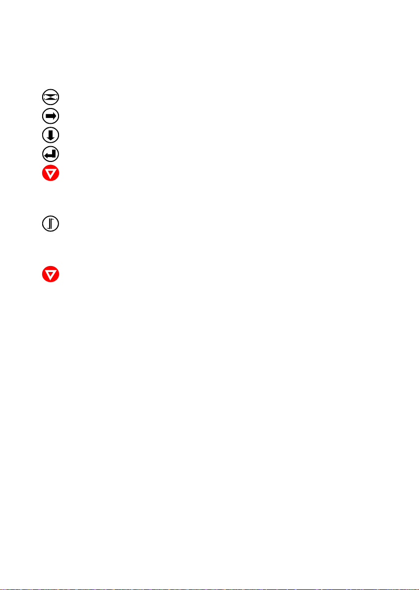
Maintenance
KEY DISPLAY
LOCAL 1 ELQ
[MENU] TEST MODES º
[ARROW RIGHT] » PRINT MENU
[ARROW DOWN] » CONFIGURATION
[ENTER] » CONFIGURATION r
[ONLINE] CONFIGURATION r
(start of the print out)
» CONFIGURATION
[FORM FEED] PAPER TEAR OFF
(short displayed)
» STOP
[ONLINE] READY 1 ELQ
Note: If it doesn’t work open the printer again. Press print head cable and its
connector once more together. Close the printer and repeat the test
printout.
5-10
Page 85

6. Troubleshooting and Diagnostics
How to Use This Section
1. Find the category to which your problem belongs. The problem categories
are:
S Power-related Problems
S Error Messages
S No Printout
S Operation-related Problems
S Print-related Problems
S Ribbon or Carriage-related Problems
For example, if the print appears very light on the paper, look into Section
"Print- related Problems".
2. Find the symptom description that most closely matches the printer
symptom. In this example you would look at the symptom "Print faint or of
poor quality."
3. Try the first suggestion under that head line.
4. If the suggestion does not cure the problem try the next suggestion.
5. If none of the suggestions enables you to continue printing or if the fault is
not listed contact your service office.
Each time the printer is switched ON the display indicates TEST while the
internal self-tests are run. If the test is completed successfully READY 1 ELQ
will be displayed. If an error message is displayed please refer to the following
section.
6-1
Page 86
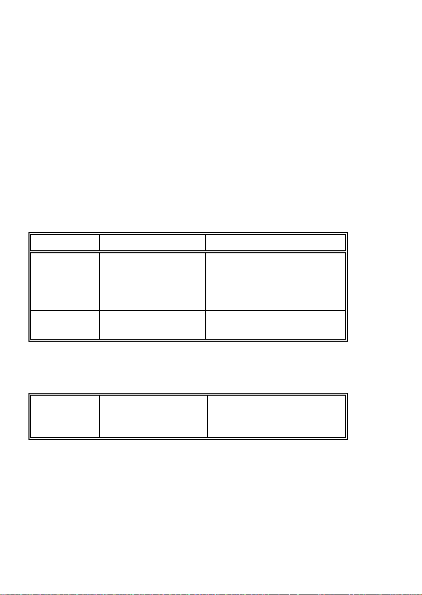
Troubleshooting and Diagnostics
6.1 Power-related Problems
Power indicator does not light when power is switched On:
S Check that the power cord and plug are securely fitted to the printer and to a
mains outlet.
S Ask for the power connector connections (and fuse) to be verified.
S Ask for the building electrical supply to be verified.
S PM correct inserted ?
6.2 Error Messages
After switching the power ON the printer runs a self test. During the test the following messages may show up on the display:
Display That means ... Cause
No information, No power S Mains cable not connected.
POWER ON
LED not not lit or ......... S PM not installed
S PM not property installed
LED lit but no Hang up in reset after S print PSU defective
reaction power on S Print CU-DEV defective
After all tests have been passed successfully the following message will be
displayed:
READY 1 ELQ Printer is OK S Printer ready for operation
or
BUSY 1 ELQ
6-2
Page 87
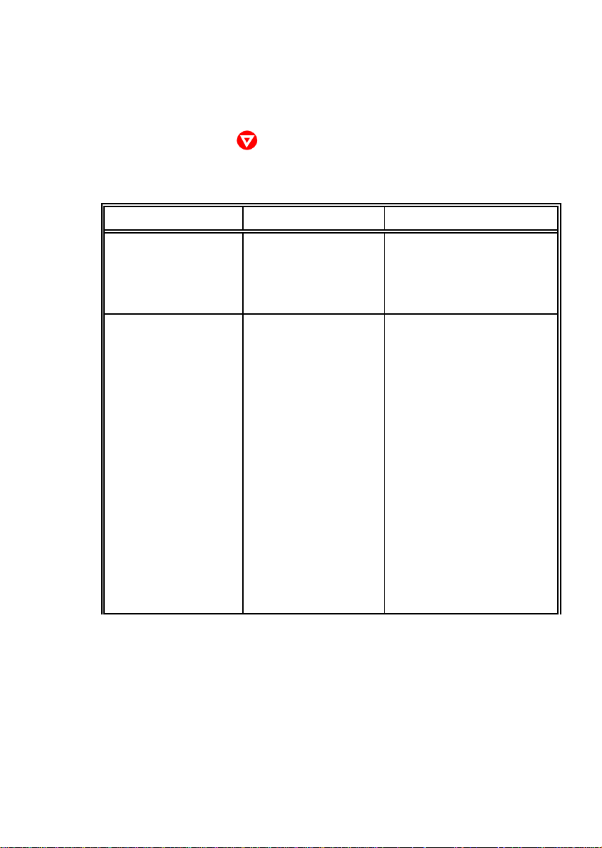
Troubleshooting and Diagnostics
During normal operation the following error messages may occur :
Note: In an error case the printer change into the OFFLINE mode. After error
correction press key to change back again into the READY mode.
If an error correction is not possible call the service of your dealer!
Display That means ... Cause / Action
BUFFER OVERFLOW Handshake protocol S Check CTR - CTS or
error XON/XOFF protocol
S Check connector
S Repeat data transfer
CARRIAGE ERROR Horizontal drive without S Paper jam
function S Print gap incorrect
S PCC-value too low
S Ribbon feed guide isn´t
aligned with print head
S Horizontal drive blocked
S Encoder strip not in
correct position
S Encoder strip is dusty
S Encoder strip missing
S Horizontal motor fault
S Print CU-DEV defective
S AGC procedure on not
workable position
S No AGC ADJUST after
print head replacement
6-3
Page 88
Troubleshooting and Diagnostics
Display That means ... Cause / Action
CHECK TOF POS Perforation isn´t S Adjust the perforation of
adjusted with the tear the form with the tear off
off edge edge by pulling the paper
forwards or backwards
S Check if print head is in its
park positon
S Ribbon cassette correct
installed ?
S see also diagram 6.8.5
Paper Jam TRF
ELECTR-FAN ERROR Fan error S Press key again
S Hardware error; call
service
FRAMING ERROR Protocol error serial S Check protocol setting of
interface printer and host
S Repeat data transfer
GAP ERROR Print gap incorrect, S Printer not locked
green ribbon support S Wrong distance between
not in right position print head and print bar
S Pins of the green ribbon
support broken
S Check if print head is in its
park positon
S See also diagram
6.8.7 Gap Error
S Error still there call service
LOCK COVER Housing will be locked S Wait MOTOR FAN ERROR H-motor fan error S Press key again
S Hardware error; call
service
6-4
Page 89
Troubleshooting and Diagnostics
Display That means ... Cause / Action
PAPER JAM ASF There are obstructions S Remove any obstacles
in the paper path S See also diagram
6.8.6 Paper Jam ASF
PAPER JAM MANUAL There are obstructions S Remove any obstacles
in the paper path S Close front cover
S See also diagram
6.8.6 Paper Jam Manual
PAPER JAM TRF Tractor cassette:
S Feeding incorrect S Check paper path
S No paper feeding S Correct paper position?
S Not enough feeding S Paper movement wrong
S Too much feeding
by tearing off
After power on:
S No paper inserted S Close front cover
S Insert paper
S See also diagram 6.8.5
Paper Jam TRF
PARITY ERROR Protocol error serial S Check protocol setting of
interface printer and host
S Repeat data transfer
PRINT HEAD ERROR Problems with the print S No ribbon run
head incline S Pins on print head
carriage defective; call
Service
S Unlock print head and
lock it again (see diagram
6.8.1 Locking Procedur)
PROCESS TIMEOUT Firmware error S Press key again
S Switch printer off and on
S Error still there, call
service
6-5
Page 90
Troubleshooting and Diagnostics
Display That means ... Cause / Action
REMOVE PAPER The paper sensor is S Remove paper
covered S Close front cover
RIBBON ERROR Ribbon problems S Unlock printer
S Open printer
S Check ribbon cassette
SYSTEM ERROR Problems with the S Switch printer off and on
system or the firmware S Error still there, call
service
UNLOCKED - S Horizontal drive S Open printer
CARRIAGE ERROR without function S Check ribbon
S Check if print head is in its
park positon
S Printer locking S Lock printer (see diagram
procedure faulty 6.8.1 Locking Procedur)
UNLOCKED COVER Rear cover will be S Wait
unlocked
UNLOCKED - S No ribbon cassette S Check ribbon cassette
CHECK RIBBON ... detected S Move print head into park
position
S Printer unlocked S Lock printer (see diagram
6.8.1 Locking Procedur)
UNLOCKED - Ribbon problems S Open printer
RIBBON ERROR S Check ribbon cassette
S Lock printer (see diagram
6.8.1 Locking Procedur
or 6.8.3 Ribbon Error)
6-6
Page 91

Troubleshooting and Diagnostics
6.3 No Printout
S Self-test printout does not start
S Make sure that you have closed the cover.
S Check if paper is loaded in the printer.
S Refer to paragraph 1.8 Paper Loading.
S Printing does not start
S Make sure that the READY or BUSY message is displayed. If there is a
different message displayed please look into the above error message
table.
S Make sure that the printer is connected to the host computer. (Refer to
paragraph 1.10 Connecting to the System). Make sure that connectors
are properly fixed at both ends.
S Make sure that the printer is receiving data from the host computer.
S Make sure that the correct protocol is enabled. (Refer to page and
appendix A Interface Description).
S Make sure that you have selected the correct port (if the shared mode
has not been selected).
S Make sure that paper is loaded.
S Make sure that the ribbon is installed.
S Examine the ribbon path.
S The ribbon feed guides are not in the right posotion (see paragraph
1.6 Ribbon Installation)
S Fanfold paper does not advance
S Make sure that the right paper tractor is selected.
S Single sheet paper does not advance
S Make sure that the paper source MANUAL or BIN x (x = 1 up to 3) is
selected.
6-7
Page 92

Troubleshooting and Diagnostics
6.4 Operation-related Problems
S Paper is not positioned at perforation for tear-off
S Select the correct form length using the Set-up feature.
S Reset top of form by moving the paper into park position.
S Paper tears or jams
S Examine the paper path; remove any obstacles
S Is the paper too loose or too tight between the tractors?
S If the transport holes are deformed at their outer edges, the paper is too
taut.
S If the paper rises between the tractors it is too loose.
S Readjust the tractor spacing so that the paper lies smoothly but without
any tension.
S Ensure that the paper is horizontally aligned on the pins.
S Paper moves out of one tractor.
S Parking paper and resetting top of form
S Tear off the paper at the perforation.
S Press .
S Press until the paper is in the park position.
S Press . Printing will resume at the top of the next form.
S Print head carriage does not move smoothly / does not move at all
S Examine the paper path. Remove any obstacles.
S Examine the carriage area for obstacles. Remove where necessary.
Press the key when the paper path is cleared.
S Make sure that the transport lock has been removed.
S Single sheets are skewed
S Adjust ASF cassette paper guides.
S You will find more information in chapter 7.2 ASF Cassette.
6-8
Page 93

Troubleshooting and Diagnostics
6.5 Print-related Problems
S Print faint or of poor quality
S Do you use the right paper? See Chapter 8 Technical Data which con-
tains the paper specification. Replace the paper if it does not comply to
this specification.
S Does the ribbon need to be changed? Replace it by a new one if
necessary.
S Is the ribbon cassette properly installed?
S Ribbon path not o.k. ?
S Print gap incorrect. Press twice.
S Coppies not dark enough. Don´t use old action paper!
S Characters are not printed evenly or are not uniform in pitch
S Examine the paper path for dirt or other obstacles that may cause the
gap between print head and platen to vary. Remove the obstacles.
S Print lines overlap
S Examine the paper path for dirt or other obstacles. Remove the
obstacles.
S Part of printed text is missing (loss of data)
S If you are using Serial communication channel check the buffer control
setting in Set-up.
S Check the data flow control setting on the host computer.
6-9
Page 94
Troubleshooting and Diagnostics
If the printout or the character set is not correct the following procedure can help
to clear the situation.
Action Result Check
Select and start PRINT No print image or S PAPER SOURCE
TEST 1 printout not complete selection
S Ribbon condition
S Print head condition
Stop SELF TEST and No printing starts S Printer ONLINE
start external printing READY
S Interface cable for
proper connection
S Interface selection
Some characters not S Emulation
correct S Character set
S National version
S Word length
S Baud rate
S Parity bit
S Protocol
6-10
Font and/or pitch faulty S Font
S Pitch
S Line space
Problem still there S Call service
Page 95

Troubleshooting and Diagnostics
6.6 Ribbon or Carriage-related Problems
S Ribbon Problems
S Make sure that the ribbon is:
S Properly tight
S Not worn out or dry
S Not torn or damaged in any other way
S Not jammed
S Ribbon turned over ?
S Carriage does not move smoothly
S Examine the paper path. Remove any obstacles. Check that all packing
material is removed.
S Examine the carriage area for obstacles. Remove where necessary.
6.7 Print Tests
There are four different print tests as well as one interface test built into the
printer.
Note: Detailed information about the print tests you will find in chapter 1.9 Test
Printouts.
6-11
Page 96
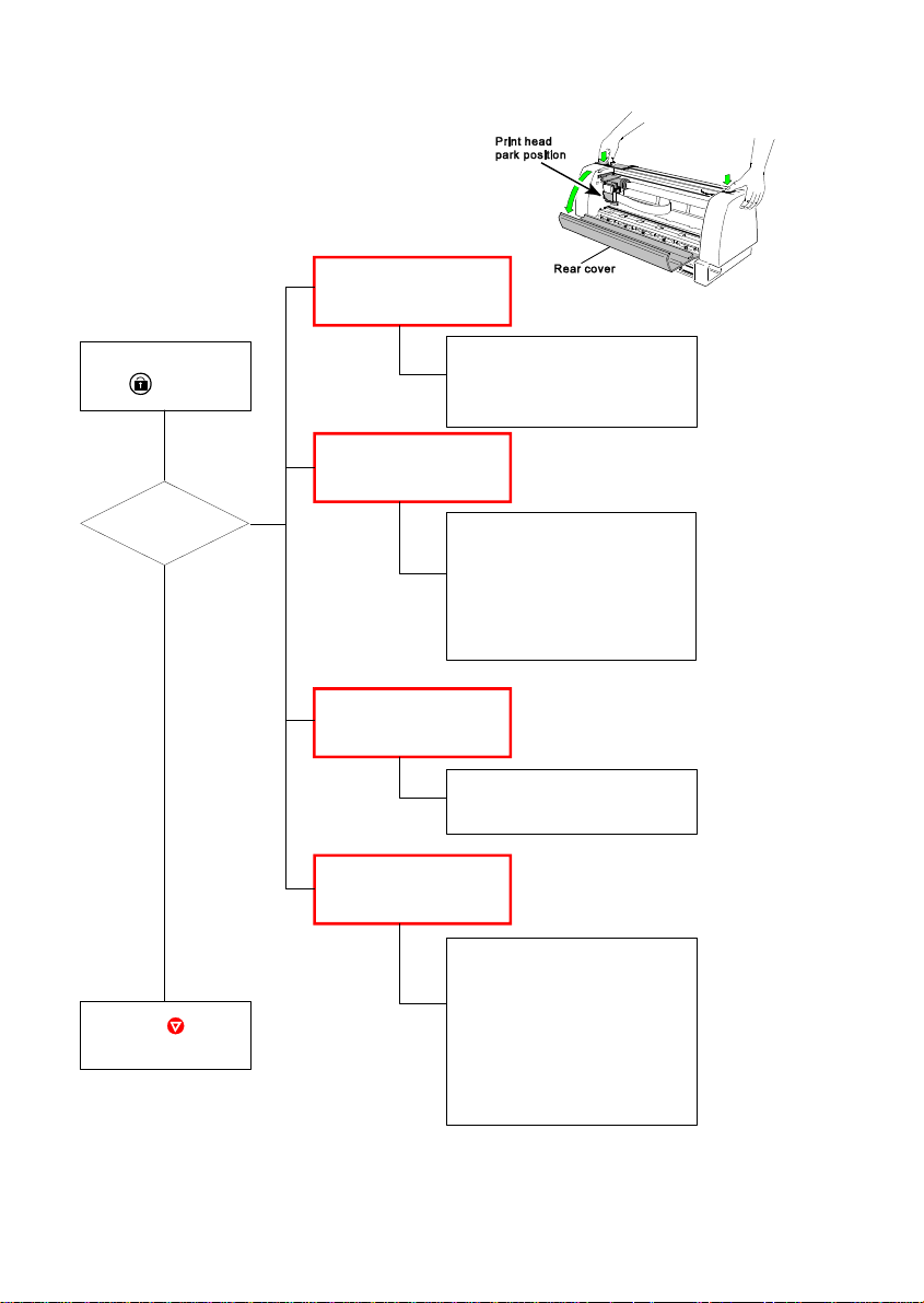
Troubleshooting and Diagnostics
6.8 Diagrams for Failure Analysis
6.8.1 Locking Procedure
Error message:
UNLOCKED -
CHECK RIBBON....
Close rear cover and
press
LOCAL
displayed ?
Yes
Press
to continue
Rear cover closed ?
Ribbon inserted ?
Ribbon movable ?
Print head in park position ?
UNLOCKED CARRIAGE ERROR
No
Open the rear cover, clean
the encoder strip and control
the position.
Ribbon correctly inserted ?
Is the green lever of the ribbon
locked in its home position
(right side) ?
UNLOCKED CHECK RIBBON ...
Check ribbon cassette and
move printhead into park
position
UNLOCKED GAP ERROR
Open the rear cover
Ribbon correctly inserted ?
Is the green lever of the ribbon
locked in its home position
(right side) ?
Green lever below the print
head ?
Pins of the green ribbon
support broken ?
Note: Remove the ribbon cassette only, if the print head is in park position.
6-12
Page 97
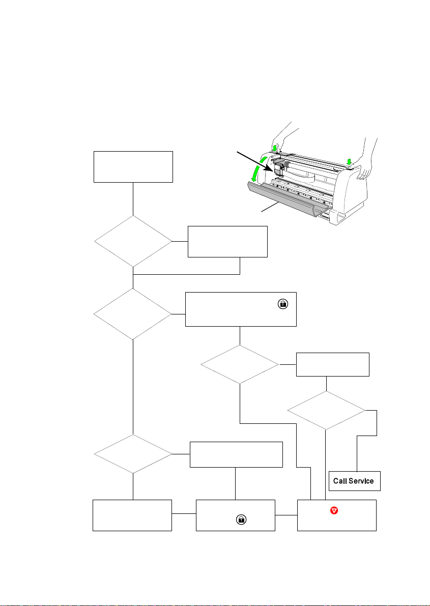
Troubleshooting and Diagnostics
6.8.2 Ribbon Unfasten Procedure
Note: Remove the ribbon cassette only, if the print head is in park position.
Print head
park position
Open rear cover
Rear cover
Print head in
park position?
Yes
Is it
possible to
remove the ribbon
cassette ?
Yes
New
ribbon cassette
required ?
Yes
Replace the ribbon
casstte
No
Move print head to
park position
Close rear cover, press
No
to lock the printer.
OK ?
Yes
No
Fix ribbon leading at home
position.
Close rear cover
and press
No
see 6.8.1 Locking
Procedure
OK ?
Yes
Press
to continue
No
6-13
Page 98
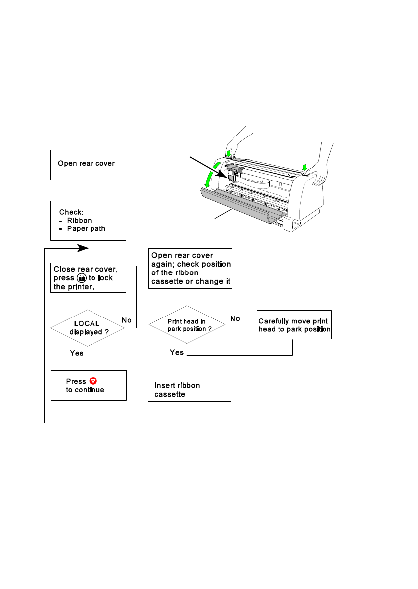
Troubleshooting and Diagnostics
6.8.3 RIBBON ERROR
That means, that the printer has tried to tense the ribbon and to fix the ribbon
feed guide into the fixing device. But there are still problems with the ribbon.
Note: Remove the ribbon cassette only, if the print head is in park position.
Print head
park position
Rear cover
1) Park Postition: Print Head is on the most right side of the printer. (The view is
from the front of the printer.)
6-14
1)
Page 99
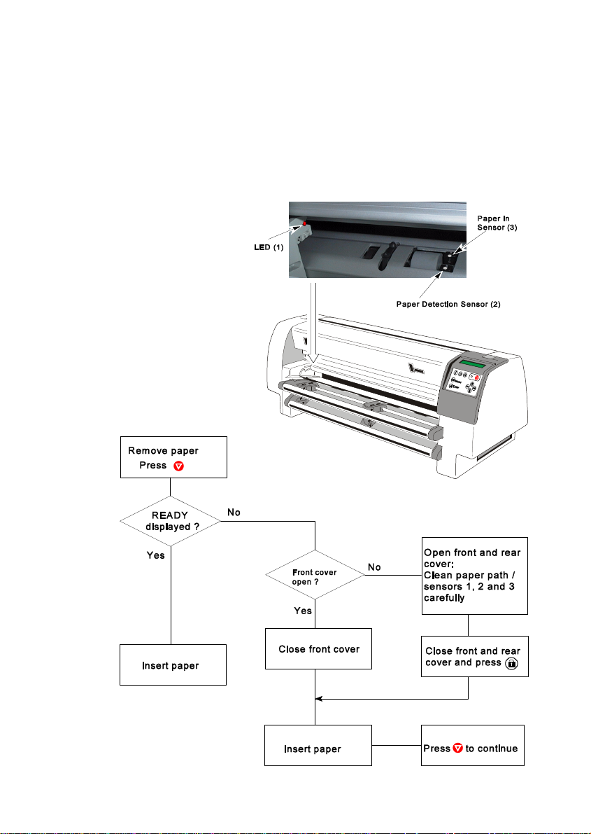
Troubleshooting and Diagnostics
6.8.4 REMOVE PAPER
That means, that a sensor isn’t free from any obstructions:
S Paper remains are in the paper path.
S Front cover isn’t closed entirely.
S Sunlight shines directly to a sensor.
S Clean the sensors 1, 2 and 3 carefully.
6-15
Page 100
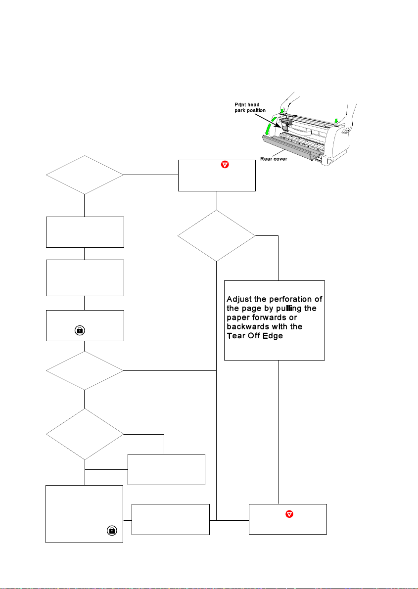
Troubleshooting and Diagnostics
6.8.5 PAPER JAM TRF (Tractor Feed)
That means, that there are obstructions in the paper path.
Note: Remove the ribbon cassette only, if the print head is in park position.
Visible paper
jam ?
Yes
Open rear cover
Remove paper
entirely.
Remove any
obstructions.
Close cover and
press
Paper jam
once more?
Yes
remove ribbon ?
No
No
No Possible to
Press
CHECK TOF POS
displayed
Perforation
adjusted with Tear
Off Edge ?
Yes
No
Yes
Remove paper and
any obstructions
entirely. Insert ribbon
cassette. Close
cover and press
6-16
Release ribbon
cassette
Insert paper again
Press
to continue
 Loading...