

Output PrintStation 70 Owner's Manual
PrintStation 60
PrintStation 70
User Manual

®Copyright1999OutputTechnologyCorporation
Thismanualreferstovariouscompaniesandproductsbytheirtrade
names.Inmostofthecases,thesedesignationsareclaimedas
trademarksorregisteredtrademarksbytheirrespectivecompanies.
2310N.FancherRd.
Spokane,WA99212-1381-USA
(509)536-0468
InternetAddress:ftp.output.com/public/output
http://www.output.com
066-0057 9 '-00
RevA

FCC Regulations
This equipment has been tested and found to comply with the limits for a
Class B digital device, pursuant to Part 15 of the FCC Rules. These limits
are designed to provide reasonable protection against harmful interference
when the equipment is operated in a commercial environment. This
equipment generates, uses and can radiate radio frequency energy and, if not
installed and used in accordance with the instruction manual, may cause
harmful interference to radio communications. However, there is no
guarantee that interference will not occur in a particular installation. If this
equipment does cause harmful interference to radio or television reception,
which can be determined by turning the equipment off and on, the user is
encouraged to try to correct the interference by one or more of the following
measures:
• Reorient or relocate the receivin g antenna.
• Increase the separation between the equipment and the receiver to
outlets on different circuits.
• Consult the dealer or an experienced radio/TV technician for help.
Changes or modifications not expressly approved by the party responsible for
compliance could void the user's authority to operate the equipment. The use
of a non-shielded interface cable with the referenced device is prohibited.
The length of the parallel interface cable must be 3 meters (10 feet) or less.
The length of the serial interface cable must be 15 meters (50 feet) or less.
Canadian D.O.C. Radio Interference Regulation
This digital apparatus does not exceed the Class B limits for radio noise
emission from digital apparatus as set out in the radio interference
regulations of the Canadian Department of Communications.
Le présent appareil numérique n'émet pas de bruits radioélectriques
dépassant les limites applicables aux appareils numériques de classe B
prescrites dans le règlement sur le brouillage radioélectrique édicté par le
ministère des communications du Canada
.
EEC Regulations
This equipment conforms to the EEC Directive 89/392 (the sound pressure,
measured according to ISO 7779, does not exceed 70 dBA).
i
Safety Information
Safety Information
✍
✍
The following areas of the printer should be covered for safety
reasons:
AA.. NNeevveerr rreemmoovvee aannyy pprriinntteerr ccoovveerr uunnlleessss iitt iiss nneecceessssaarryy ffoorr tthhe
iinnssttaallllaattiioonn ooff aa pprriinntteerr aacccceessssoorryy aanndd eexxpprreessssllyy ddeessccrriibbeedd iinn tthhiis
.
mmaannuuaall.
B
B
.
PPlleeaassee rreettaaiinn tthhee pprriinntteerr ccoovveerrss iinn aa ssaaffee ppllaaccee bbeeccaauussee tthheeyy sshhoouulld
.
bbee rreeiinnssttaalllleedd iiff yyoouu ddeecciiddee ttoo rreemmoovvee aannyy pprriinntteerr aacccceessssoorryy.
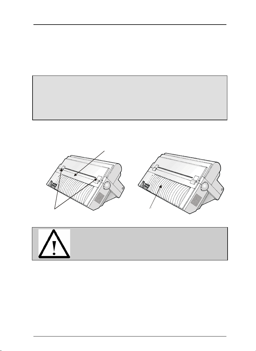
Rear Cover
Paper Stacker Openings
The above openings must always be protected with
their cover when the corresponding option is not
installed. Do not touch inside and do not insert any
object into these openings or into the gears.
La rg e Re a r Co v e r
e
s
.
d
ii

Table of Contents
Table of Contents
Getting to Know Your Printer ................................................................1
Unpacking Your Printer......................................................................1
PrintStation 60 & PrintStation 70 Parts............................................2
Front View........................................................................................2
Rear View .........................................................................................2
Setting Up Your Printer ..........................................................................3
Choosing a Suitable Location..............................................................3
Printer Assembly .................................................................................4
Removal of the Shipment Locks......................................................4
Ribbon Cartridge Installation .........................................................4
Upper Push Tractor Installation (option).......................................7
Host Computer Connection.................................................................9
Printer Driver Selection ......................................................................9
Power Connection ..............................................................................10
Selecting the Display Language..........................................................11
Configuring the Printer.........................................................................12
Operator Panel Presentation ............................................................12
Display Messages...........................................................................12
Indicators........................................................................................13
Function Keys.................................................................................13
Printer Setups....................................................................................17
Entering the Printer Setups..........................................................17
Moving within the Printer Setups ................................................17
Leaving the Printer Setups ...........................................................17
Power-On Configuration....................................................................18
Entering the Power-On Configuration .........................................18
Program Setup ...................................................................................30
Entering the Program Setup .........................................................30
How to Select the Paper Path ...........................................................40
iii

Table of Contents
How to Use the Tear-Off Function....................................................41
Selection of the Paper Size ............................................................41
Adjusting the Tear-Off Position ....................................................41
Selection of the Tear-Off Mode......................................................42
How to Lock/Unlock the Access to the Printer Setups....................43
Paper Handling......................................................................................44
Paper Paths........................................................................................44
Fanfold Paper Specifications.............................................................45
Loading Fanfold Paper ......................................................................45
Loading Paper Using the Lower Tractor ......................................45
Loading Paper Using the Upper Tractor (option)........................50
Printer Maintenance and Troubleshooting.........................................53
Cleaning the Printer..........................................................................53
Replacing the Ribbon Cartridge........................................................54
Printing the Self Test ........................................................................55
Error Handling...................................................................................55
Printer Specifications...........................................................................58
iv
Getting to Know Your Printer
(
)
Getting to Know Your Printer
• 18 Needle Print Head
• 136 columns
• PS60 model: Draft printing at 500 cps, HS Draft printing at 600 cps, LQ
printing at 210 cps, DP Text printing at 350 cps. PS70 model: Draft
printing at 700 cps, LQ printing at 210 cps, DP Text printing at 350 cps.
• IBM Proprinter XL III, Personal Printer 2381 and EPSON FX 1050
emulations
• High Resolution Graphics Printing (240 x 144 dots per inch)
• Multiple copies (1 original and 7 copies)
• Automatic paper path selection
• Easy operability via operator panel setup and software commands
• Special Windows print drivers
• Plug & Play capability for Windows 95
• Bi-directional IEEE 1284 parallel interface and standard serial RS-232/C
and RS-422/A interface
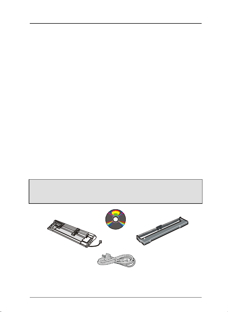
Unpacking Your Printer
The following items are included in the box:
✍
The user manual is on the CD-ROM.
If you find any damage to t he pri nter, notify your deliv ery person immediately.
CD-ROM
Upper Push Tractor
Option
Power Cable
Ribbon Cartridge
1
Getting to Know Your Printer
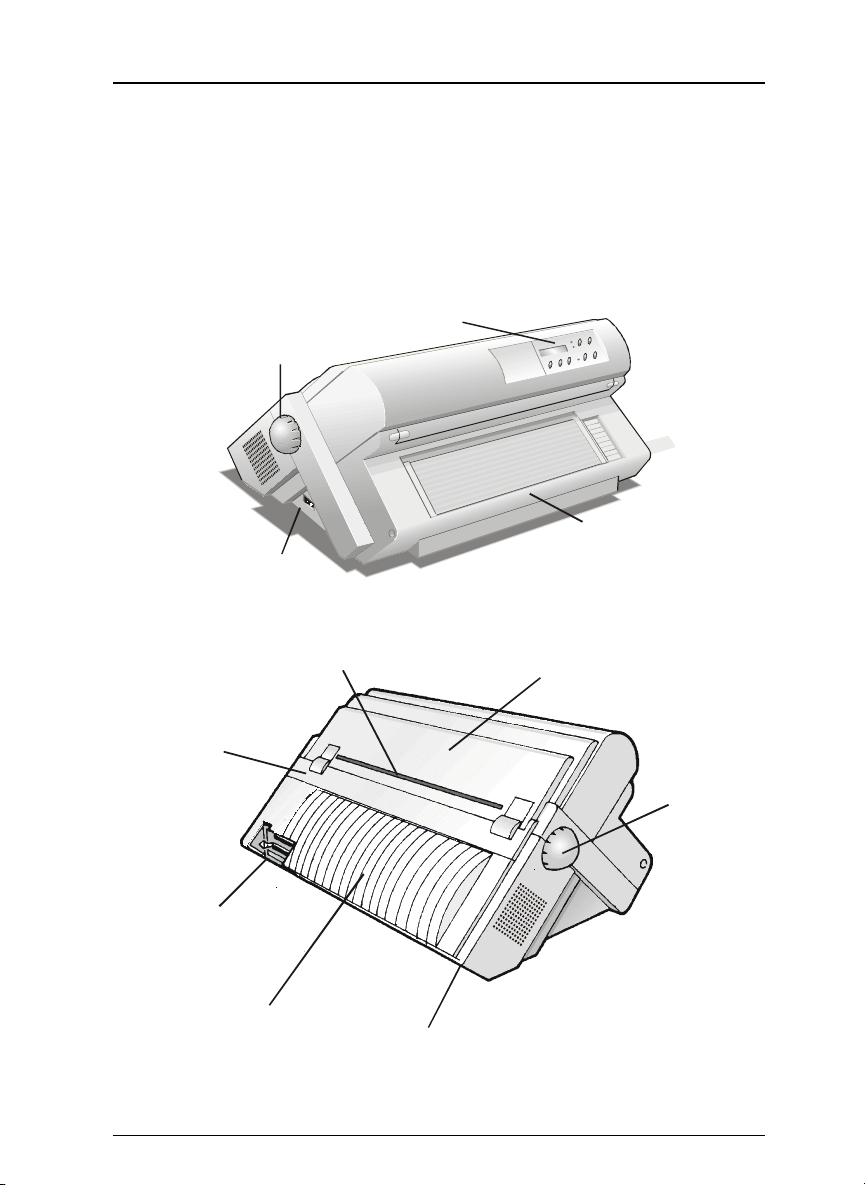
PrintStation 60 & PrintStation 70 Parts
Front View
Operator Panel
Paper Knob
Pu s h Tracto rs Co v er
Power Switch
Rear View
Rear Paper Slot
Top C ove r
Rear Cover
Interface Con n e c tors
Large Rear Cover
2
Paper K nob
Power Cable Connector

Setting Up Your Printer
Setting Up Your Printer
Choosing a Suitable Location
Consider the following points when you choose the location for your printer:
• The distance between the printer and the host computer must not exceed
the length of the interface cable;
• The location must be sturdy, horizontal and stable;
• Your printer must not be exposed to direct sunlight, extreme heat, cold,
dust or humidity (see "Printer Specifications" at the end of manual);
• You need an AC power outlet compatible with the plug of the printer's
power cord. The voltage of the outlet must match the voltage shown on
the printer's Rating Plate;
Additionally, you must make sure that when you install the printer in the
selected location, there are sufficient clearances on all sides for easy
operation. The required space is shown below:
80 cm
31.5 in.
1
0
0
3
9
c
.
m
4
i
n
m
c
0
2
n
i
9
.
7
1
0
3
0
9
c
.
4
m
i
m
c
0
2
n
i
9
.
7
n
3
Setting Up Your Printer
Printer Assembly
Removal of the Shipment Locks
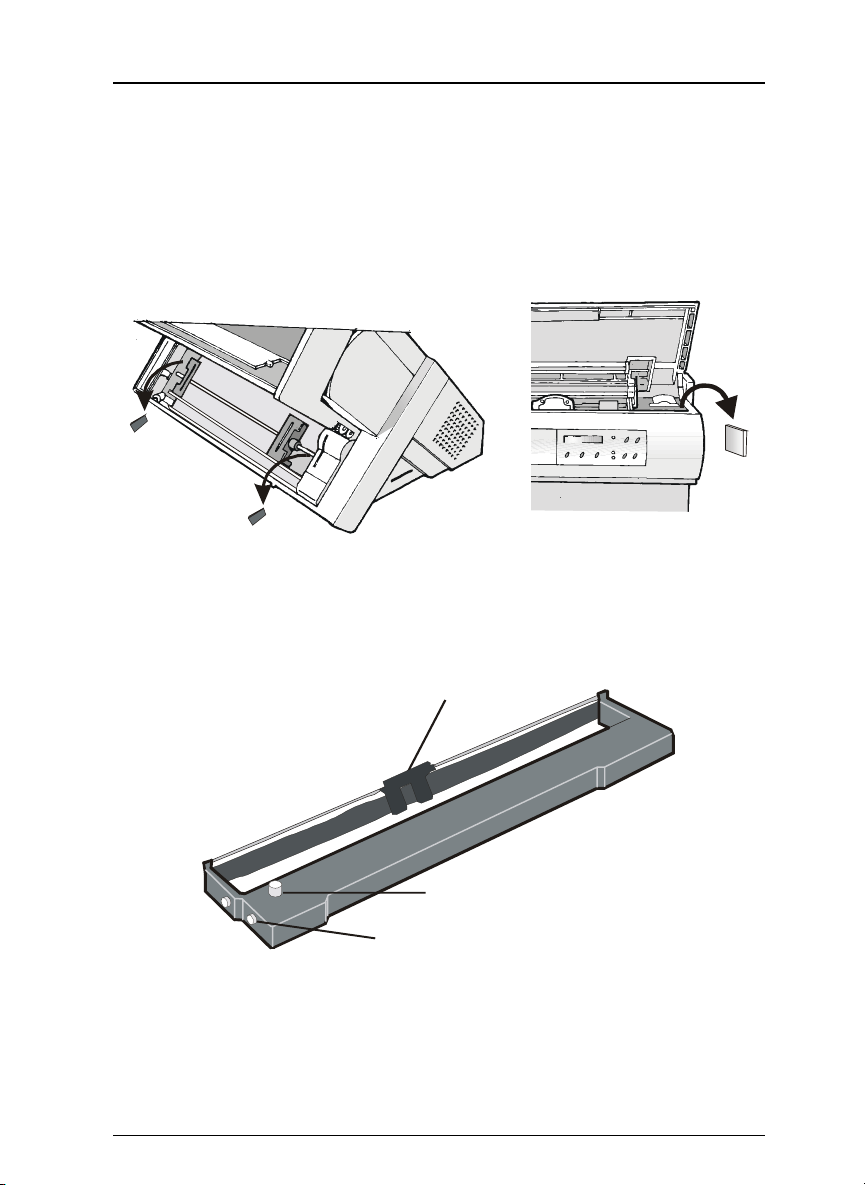
Open all the printer covers and make sure that you remove all the shipment
locks (blocks and wedges) from the printer.
Ribbon Cartridge Installation
1. Make sure that the printer is turned off.
2. Find the ribbon cartridge among the accessories.
Ribbon guide
Tension Knob
Cartridge Pin
4
Setting Up Your Printer
n
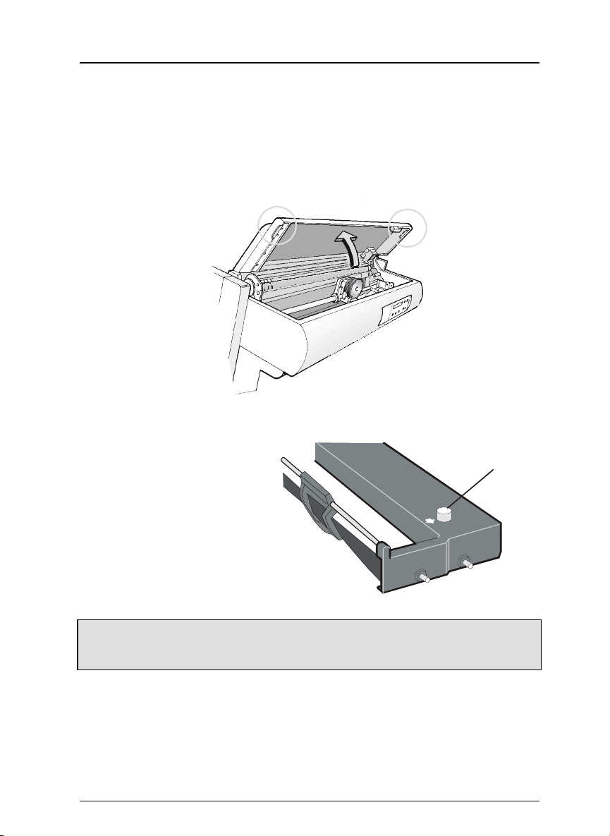
3. Turn the printer on. The print carriage prepares for ribbon cartridge
installation.
4. Open the top cover using the small handles on either side of the top cover.
The print head moves towa rds the fro nt of the printe r for eas ier ca rtridge
installation.
5. Before installing the ribbon
cartridge turn the ribbon
winding knob in th e arrow
direction (located on the
cartridge) to take up slack
in the ribbon.
To avoid damage to the ribbon, do not turn the winding knob in the wrong
✍
direction.
Ribbon Tensio
Knob
5
Setting Up Your Printer
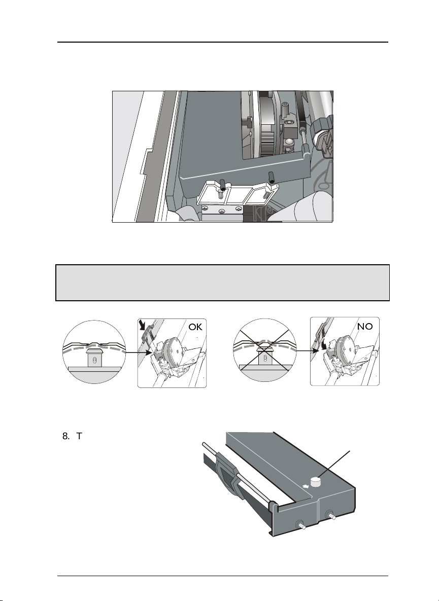
6. Align the cartridge pins with the locking grooves on the left and right
cartridge supports.
7. Slide and insert the ribbon guide between the print head and the ribbon
guide mask holding it perpendicular to the print head.
Make sure that the ribbon is inserted correctly between t he print head and the
✍
print head mask.
8. Turn the ribbon winding
knob in the a rrow dire ction
(located on the cartridge) to
take up slack in the ribbon.
6
2.
12
Ribbon Tension
Knob
Setting Up Your Printer
9. Push the cartridge down gently until it clips into place at all four locking
points.
10. Turn the ribbon winding knob a gain in the di rection of the arrow to ta ke
up slack in the ribbon.
11. To ensure that the ribbon guide runs freely along the ribbon, manually
move the print carriage horizontally.
If you need to replace the used ribbon cartridge, see "Replacing the Ribbon
Cartridge" on page 54.
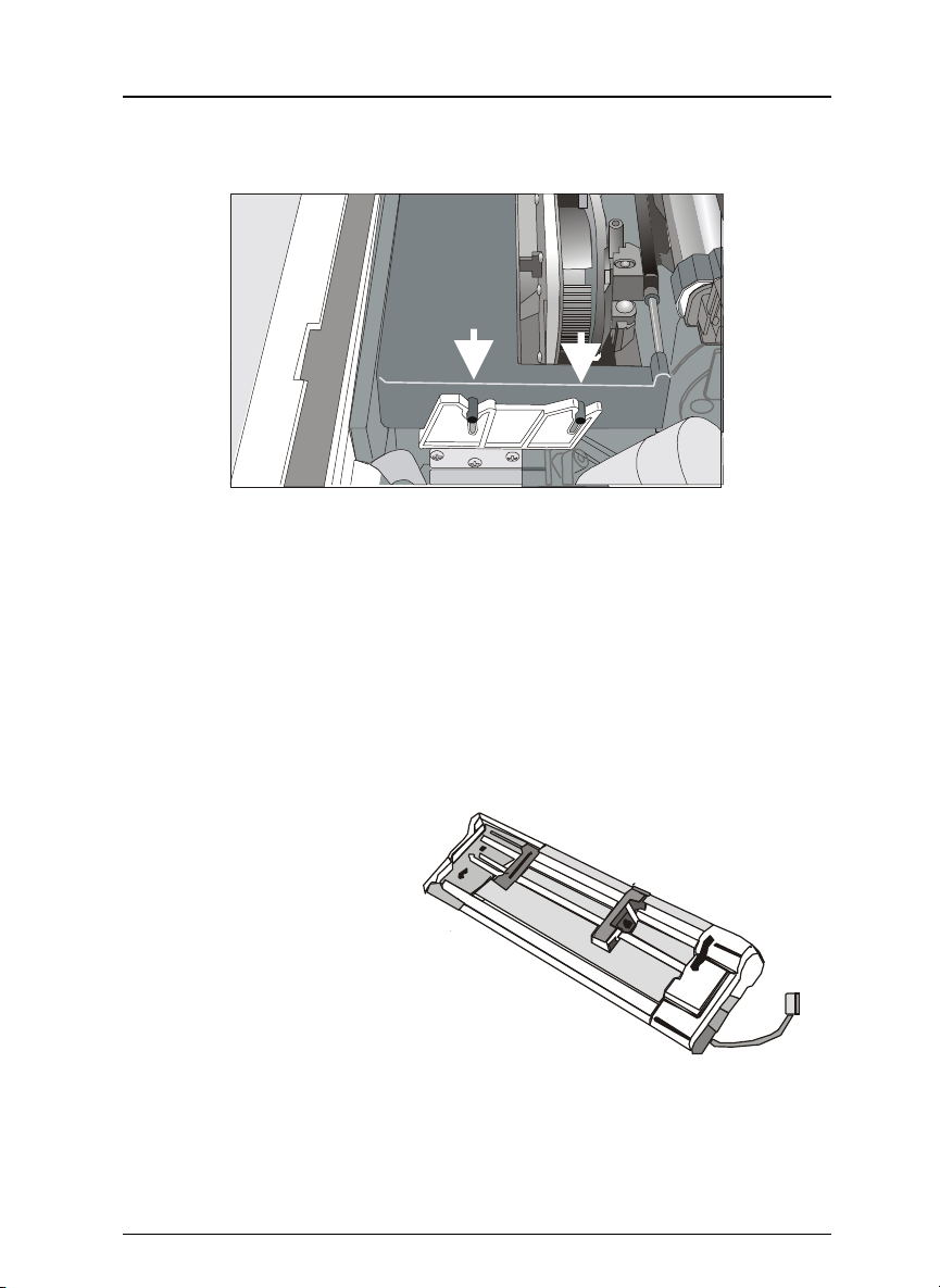
Upper Push Tractor Installation (option)
A second optional push tracto r unit unit ca n be i nsta lle d in fro nt po siti on (o n
the lower push tractor).
1. Find the optional upper
push tractor.
7

Setting Up Your Printer
2. Install the upper push tractor aligning both its hooks with the lower push
tractor pins and inserting them into the corresponding pins. Push the
upper tractor until it is fully engaged. In sert the connector cable in the
electrical connector located in the lower push tractor.
Lower Tracto r P in
Up p e r Tractor H o o k
Electrical Connector
Connector Ca ble
3. The upper push tractor must be installed as shown in figure.
4. If you need to remove the upper push tractor, turn the printer off. Take
the connector cable off and press on the internal levers (located in the
upper push tractor hooks) to disengage the tractor.
8

Setting Up Your Printer
Host Computer Connection
This printer can be connected to your host computer via two available
interfaces. The interface connectors are located on the rear of the printer.
• A bi-directional IEEE1284 parallel interface
• A RS-232C/422A serial interface
Before connecting the int erface cable, make sure that the pri nter and the host
✍
Insert the parallel interface cable into the parallel connector and fasten it by
means of the clips.
Insert the serial interface cable into the serial connector, and fasten it using
the two screws..
computer are turned OFF .
Parallel Interface Serial Interface
Printer Driver Selection
Windows printer drivers are included with the printer. Follow the
instructions in the readme file on the CD-ROM.
In a WINDOWS 95 environment the printer supports the Plug & Play
feature.
The printer drivers of all Output Technology printers can be found at the Internet
✍
Address http://www.output.com.
9
Setting Up Your Printer
Power Connection
MMaakkee ssuurree tthhaatt tthhee ppoowweerr oouuttlleett mmaattcchheess tthhee ppoowweerr rraattiinngg ooff tthhee pprriinntteerr.. SSeee
tthhee nnaammee ppllaattee ooff tthhee pprriinntteerr,, tthhaatt yyoouu ffiinndd uunnddeerr tthhee llaarrggee rreeaarr ccoovveerr.. IIn
ccaassee tthhee ppoowweerr rraattiinngg ddooeess nnoott ccoorrrreessppoonndd DDOO NNOOTT CCOONNNNEECCTT TTHHE
PPRRIINNTTEERR TTOO TTHHEE MMAAIINNSS.. CCoonnssuulltt yyoouurr ddeeaalleerr ffoorr hheellpp.
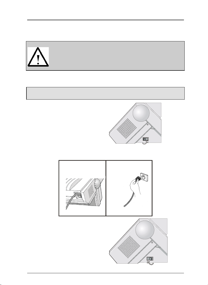
1. Make sure the power outlet is near the printer location and easily
accessible.
✍
2. Make sure that the power switch
3. Insert the power cable plug into the printer connector and the other
Always use a grounded outlet.
is in 0 position (OFF).
power cable end into a convenient outlet.
.
12
e
n
E
4. To turn the printe r on, press the
power switch in the
I position (ON).
10
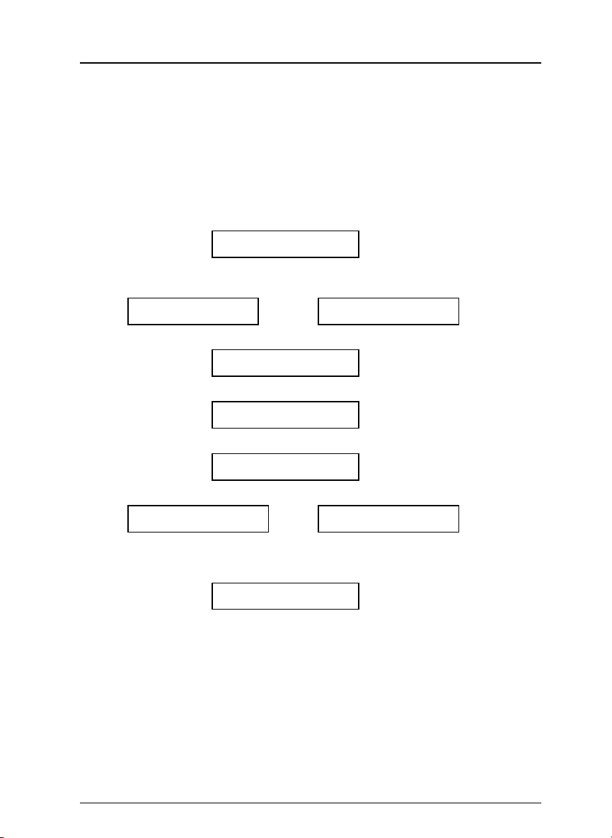
Selecting the Display Language
Selecting the Display Language
The display messages for this printer can be displayed in five different
languages: English (Default), French, German, Italian and Spanish. To
select the language, that you prefer, proceed as follows:
1. Press the PROGRAM key while powering the printer on and keep it
pressed until the following message is displayed
RELEASE THE KEY
2. When the PROGRAM key is released, the following messages are
displayed :
PS 60 or PS 70
then,
PRINT OUT? NO
3. Press the ↓ key to e n ter the setup. The first setup item is displayed:
PARALL INTERFACE
4. Press the ↓ key until the language first level function is displayed:
FUNCTIONS
5. Press the → key to pass to the second level functions:
HIGH SPEED or SEQUENCE NONE
(PS60 model) (PS70 model)
6. Press the ↓ key until the setup language is displayed:
MENU ENGLISH
7. Press the → key to scroll the setup languages. When the desired language
is displayed, press the PROGRAM key to select it. The printer exits the
setup. From now on the display messages appear in the selected
language.
11
Configuring the Printer
PROGRAM
PROGRAM
QUIET
Configuring the Printer
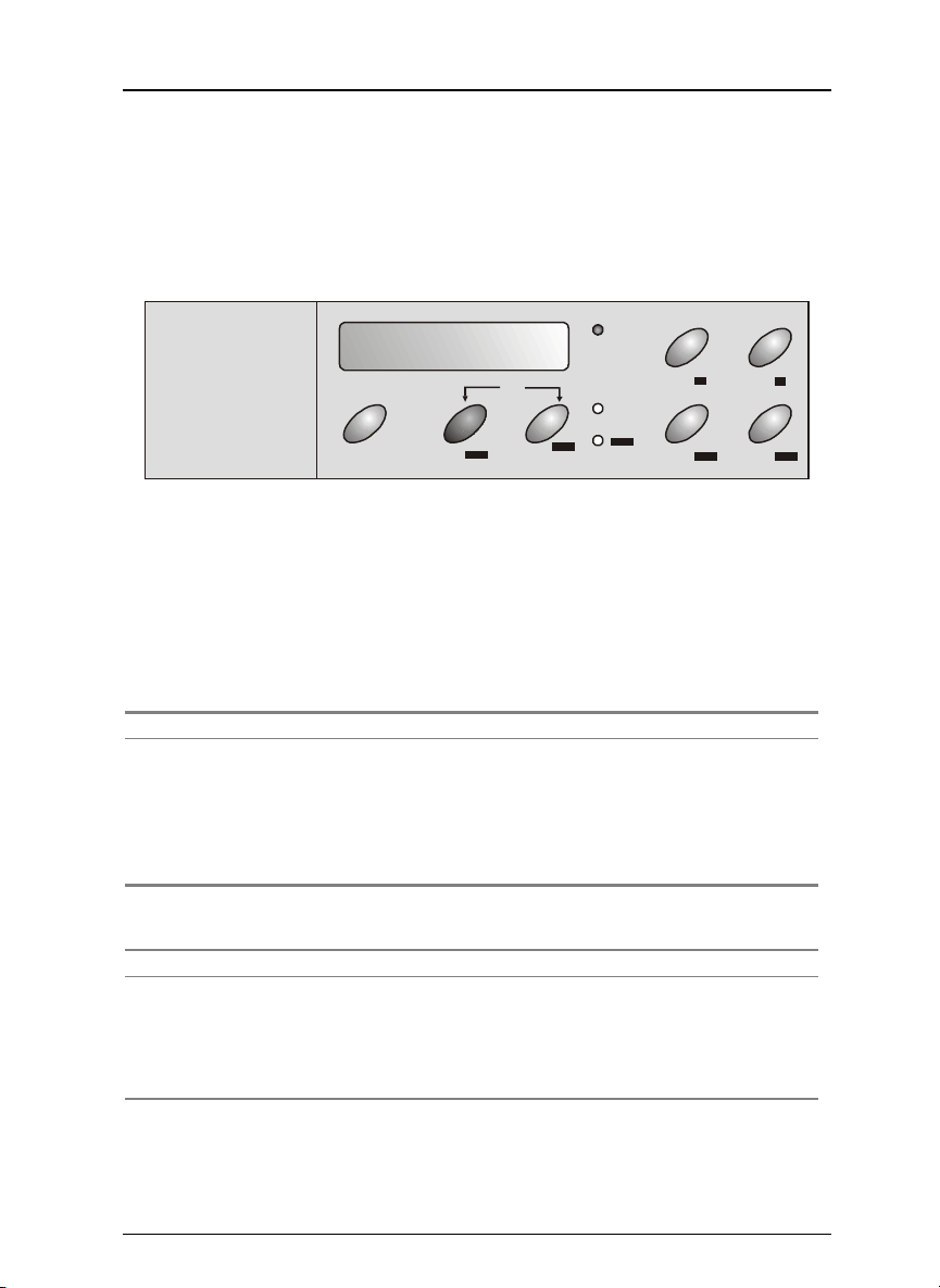
Operator Panel Presentation
The operator panel enables you to perform many of the printer functions
including paper path selections, font selection and the printer setup.
READY
ON LINE
The operator panel consists of:
• A 16 character display (Liquid Crystal Display)
• Three function mode indicators
• Seven function keys
Display Messages
Instruction Messages
Message Description
LOAD LOWER PUSH
LOAD UPPER PUSH
RELEASE KEY
User Intervention Messages
Message Description
PARK: SURE?
MACRO CHANGING
PATH CHANGING
These messages are displayed when the
corresponding paper path is out of paper.
The printer displays only the messages related to
the installed devices.
This message is displayed when you can release
the PROGRAM key while powering on the printer.
The user must confirm the parking of the paper.
The macro has been changed and the printer is
updating the settings.
The path has been changed and the printer is
updating the settings.
PITCH
SHIFT
SHIFT
MICRO FEED
LFLOAD/FF
PARK
↓ ↑
MACRO FONT
PATH
12
Status Messages
READY
PROGRAM
SHIFT
Message Description
font cpi
LOWER PUSH
MENU LOCKED
MENU UNLOCKED
MICRO FEED DOWN ↓
MICRO FEED UP ↑
QUIET PRINT OFF
QUIET PRINT ON
UPPER PUSH
SELF TEST
The printer is offline or online without printing.
The lower push paper path is selected.
The printer displays this message when the access
to the Printer Setups has been locked.
The printer displays this message when the access
to the Printer Setups is not locked.
The paper is fed in microsteps downwards when
pressing the arrow key.
The paper is fed in microsteps upwards when
pressing the arrow key.
Printing at normal noise level.
Printing at reduced noise level.
The upper push paper path is selected.
Printing the self-test page.
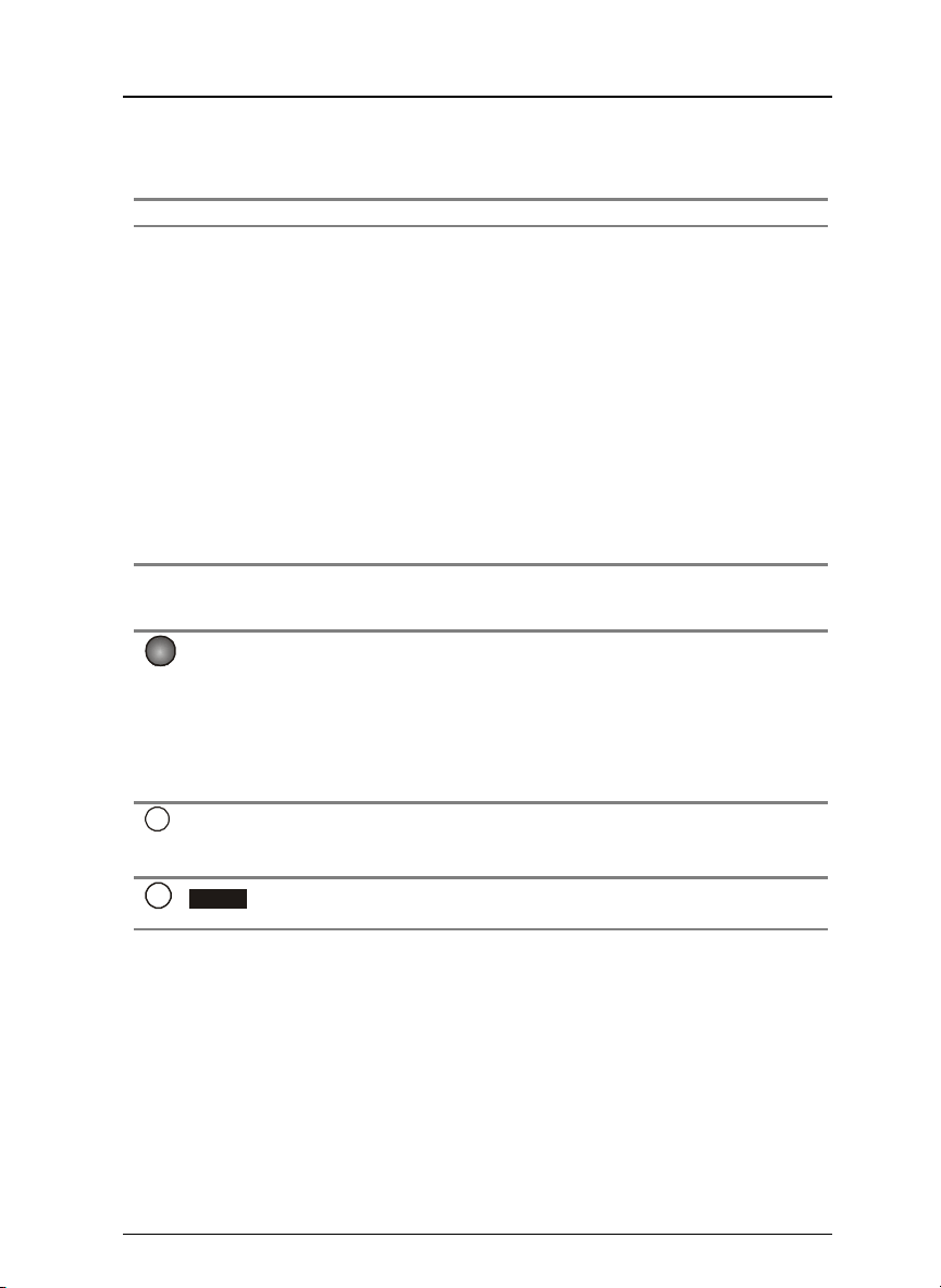
Indicators
Lit when the printer can receive and print data
(printer online).
Blinks when there is data in the buffer and the
printer is offline.
Unlit, when the printer is disabled and the buffer
does not contain any data, or during the
initialization, setup or tests.
Blinks when one of the printer setup procedures
has been selected: Program Setup or Power-On
Configuration.
Blinks when the alternate function of the keys has
been enabled pressing the SHIFT key.
Configuring the Printer
Function Keys
The function keys are enabled, when the printer is offline. (READY indicator
unlit). The function keys have three functions each.
13

Configuring the Printer
Normal Function
Shift Function
Program Function
The normal function of the keys does not require
previous action to select it. This function is indicated in
black characters beside the funct ion keys.
The alternate function is selected pressing the
SHIFT key.
The alternate functions of the keys are described on
the gray areas beside the keys. The SHIFT indicator
blinks.
This function is not enabled, if the printer is in
setup mode.
The program function is selected pressing the
PROGRAM key, where:
• If you press the key while powering on the
• Pressing the key when the printer is enabled
In the Program Setup mode only the four arrow
keys and the PROGRAM key are enabled.
When the printer is in se tup mode, the PROGRAM
indicator blinks.
ON LINE Key
ON LINE Normal Function
Program Function Pressing this key, the input buffer is
printer, the Power-On Configuration is selected.
without printing or disabled (READY indicator
unlit), the Program Setup is selected.
• Enables or disables the printer.
• If this key is pressed while powering
the printer on, the self test i s printed;
the printout is stopped pressing this
key again.
• In an error condition, once the error
cause has been removed, press this
key to enable the printer.
• If the Tear-Off Function in the
Program Setup is set to Manual, press
this key to position the paper for the
Tear-Off.
cleared and a break (250 msec.) on a
serial interface is sent. The message
RESET & BREAK is displayed.
14

PROGRAM Key
PROGRAM
PITCH
Normal Function Enables the printer setups as follows:
Shift Function Selects the pitch to be used with the
Program Function Exits the current printer setup. See later
SHIFT Key
SHIFT
Normal Function Enables the alternative ke y functions.
Shift Function Disables the alternative key functions.
LOAD/FF Key
LOAD/FF
↑
↑
Normal Function Executes a Form Feed (FF): when paper
Shift Function Moves the paper forward in microsteps.
Program Function Scrolls the parameters of the functions or
Configuring the Printer
• Pressing this key while powering on
the printer, the Power-On
Configuration is selected.
• Pressi ng this key when the printer is
enabled without printing or disabled
(READY indicator unlit), the Program
Setup is enabled.
currently selected fon t. The selected pitch
is valid until the printer is turned off.
“Leaving the Printer Setups” o n page 17.
is loaded into the printer, it advances to
the following page; if no paper is loaded,
it is positioned for printing.
Keeping the key pressed the paper is
moved continuously at increasing speed.
macros backwards.
LF Key
LF
↓
↓
Normal Function Performs a line feed according to the
current line spacing settings.
Shift Function Moves the paper backward in microsteps.
Keeping the key pressed the paper is
moved continuously at increasing speed.
Program Function Scrolls the setup and macro functions
forward.
15
 Loading...