

Page 1

LaserMatrix
®®®®
LaserMatrix
LaserMatrixLaserMatrix
Floor Model Stacker
Floor Model Stacker
Floor Model StackerFloor Model Stacker
(Full Capacity Models LM1000A115 & LM2400A100)
Operator’s Guide
Operator’s Guide
Operator’s GuideOperator’s Guide
Part No: 066-00452-02
January 23, 1998 — Rev. G
Page 2

COPYRIGHT
COPYRIGHT 1994, OUTPUT TECHNO
COPYRIGHT COPYRIGHT
All rights reserved under the Berne Convention.
TRADEMARKS
TRADEMARKS
TRADEMARKSTRADEMARKS
LaserMatrix is a registered trademark of Output Technology
Corporation.
PARTS AND SERVICE
PARTS AND SERVICE
PARTS AND SERVICEPARTS AND SERVICE
Contact Output Technology Corporation for parts and service. Have the
serial number of your printer and LaserMatrix Stacker handy so that we
can serve you more quickly.
We suggest you use genuine Output Technology Corporation supplies
and authorized service centers. Contact us at —
1994, OUTPUT TECHNOLOGY CORPORATION
1994, OUTPUT TECHNO 1994, OUTPUT TECHNO
(509) 536-0468 (Voice) or (509) 533-1280 (Fax)
LOGY CORPORATION
LOGY CORPORATIONLOGY CORPORATION
Output Technology maintains a Bulletin Board System (BBS) service.
In the U.S.A., call (509) 533-1217 to access our BBS service for the
very latest drivers, firmware, pricing, maintenance and troubleshooting
aids, and application information. Also, you can contact us at —
FTP: ftp.output.com/public/output
WWW: http://www.output.com
CONTENTS
CONTENTS
CONTENTSCONTENTS
Introduction.......................................1 Setup.................................17
Paper & Label Requirements............2 Operation..........................20
Floor Model Stacker Specifications..3 Maintenance .....................25
Unpacking & Installation..................4 Troubleshooting................26
Assembly...........................................7 Parts & Accessories..........27
Page 3
INTRODUCTION
INTRODUCTION
INTRODUCTIONINTRODUCTION
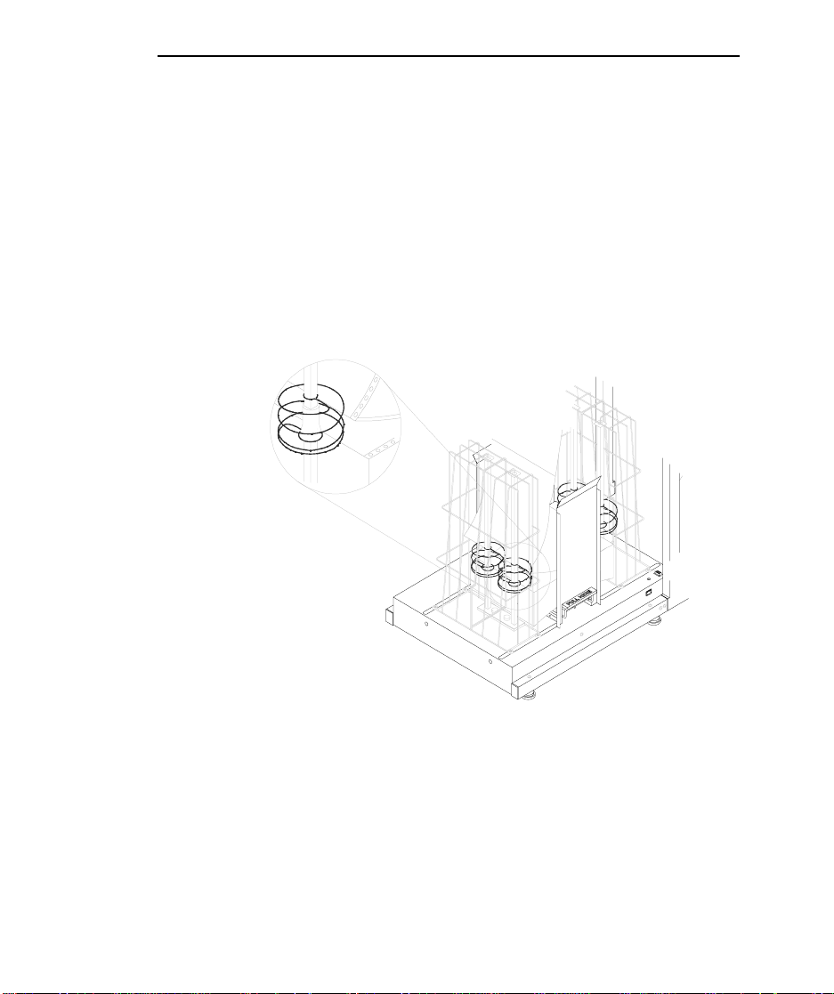
The LaserMatrix® Floor Model Stacker (Models
LM1000A115 & LM2400A100) will stack up to one full box of
printed forms from a LaserMatrix printer.
In the automatic mode, the stacker is controlled by the
printer. When the printer prints, the stacker turns two pairs of
floating helical coils which “refold” and then stack the fanfolded
paper. The coils float up with the paper as the stack grows in
height.
LaserMatrix Floor Model Stacker 1
LB0-B1
The LaserMatrix Stacker solves a problem common to
continuous form laser printers. The problem arises when a laser
printer fuses toner to the paper. In the process, heat and pressure
from the fuser iron out the perforations in the forms. The
“ironed-out” forms are more difficult to refold and stack.
Page 4

2 LaserMatrix Floor Model Stacker
The LaserMatrix Floor Model Stacker allows you to
reliably print large jobs unattended — up to one full box of
paper. The stacker handles most grades of fanfolded paper and
label stock made for a laser printer.
NOTE: Due to variations in manufacturing process, quality,
and composition of forms, Output Technology cannot guarantee
satisfactory performance with all forms. Forms should be tested
to verify satisfactory performance prior to purchasing forms.
The stacker also includes a convenient and stable platform
for the printer itself.
PAPER &
PAPER & LABEL REQUIREMENTS
PAPER &PAPER &
LABEL REQUIREMENTS
LABEL REQUIREMENTS LABEL REQUIREMENTS
Paper Type: fanfold, single-part paper with a bond
weight of 18 to 24 lb (65 to 90 g/m
and a caliper thickness of 3.2 to 4.5 mil
(0.081 to 0.114 mm). Prefer 24 lb paper
without
Label Type: fanfold labels with a caliper (thickness)
not to exceed 7.5 mil (0.190 mm)
Sheet Lengths: variable from 6 to 14 in. (approx. 152 to
355 mm), perf to perf
Sheet Widths: variable from 4 to 10 in. (approx. 101 to
254 mm), including
laser (clear perf) perforations
1
/2 in. tractor strips
2
)
Page 5

LaserMatrix Floor Model Stacker 3
Stack Limit: up to 15 in. (approx. 380 mm) in height
or about 2000 sheets of 24 lb bond
paper
FLOOR MODEL STACKER
FLOOR MODEL STACKER SPECIFICATIONS
FLOOR MODEL STACKER FLOOR MODEL STACKER
Width: 20 in. (approx. 508 mm)
Length: 37 in. (approx. 940 mm)
Height: 30 in. (approx. 762 mm)
Weight: 43 lb (approx. 20 kg)
Shipping Dimensions: 22 x 26 x 33 in. (approx. 560 x 660 x
Shipping Weight: 55 lb (approx. 25 kg)
SPECIFICATIONS
SPECIFICATIONSSPECIFICATIONS
840 mm)
Power Supply: 12 vdc at 800 ma. One of two power
supplies is shipped with the stacker:
either a UL/CSA, 120 vac, 60Hz, plugin power supply, or a 230 vac, 50Hz, inline power supply with a TÜV power
cord
Power Consumption: not more than 10 w
Page 6

4 LaserMatrix Floor Model Stacker
UNPACKING & INSTALLA
UNPACKING & INSTALLATION
UNPACKING & INSTALLAUNPACKING & INSTALLA
You will need a utility knife for unpacking the container
and a small, flat-blade screwdriver to fasten cable connectors.
1. Inspect shipping container for damage. Report damage to
carrier immediately.
2. Stand shipping container upright.
3. Use a utility knife to remove one side of the container.
4. See Caution below, then move contents to installation site.
! CAUTION !
If you use a lift truck, only lift along bottom rails of the
stacker. Do not use a lift truck after plastic strap has
been removed.
TION
TIONTION
5. Remove plastic stretch wrap.
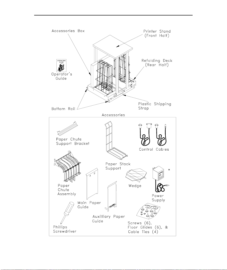
6. Remove accessories box. Also, remove bubble package
resting on refolding deck. Check contents of box and
package against the following illustration.
7. Cut plastic strap holding cardboard pad to bottom of deck.
8. Use the screwdriver provided to remove two screws (with
nylon washers) holding printer stand to refolding deck.
Lift off stand and then re-install screws and washers to
deck.
Page 7

LaserMatrix Floor Model Stacker 5
9. Lift refolding deck off cardboard pad. Save all packing
materials.
Page 8
6 LaserMatrix Floor Model Stacker
LB0-C5
* UL/CSA, 120 vac, plug-in power supply is shown here. A 230 vac, in-line power supply is available.
Page 9

ASSEMBLY
ASSEMBLY
ASSEMBLYASSEMBLY
1. Move refolding deck and printer stand onto a hard, flat
2. Position U-channels of printer stand rails just opposite
3. Insert channels of printer stand into rails of refolding deck
LaserMatrix Floor Model Stacker 7
surface.
open rails of refolding deck, as shown in the next
illustration.
NOTE: It is possible to install the deck backwards. Make
sure you orient the deck, as shown in the illustration, so
that the corner of the deck with the manual mode switch is
located nearest the printer stand.
so that two pairs of screw holes line up. (It may be
necessary to temporarily loosen the four screws that
secure the refolding deck to its rails.)
4. Secure the two halves of the stacker with the screwdriver
and four,
accessory box.
5. If necessary, retighten screws to resecure deck to its rails.
3
/8-in.-long Phillips screws provided in the
Page 10

8 LaserMatrix Floor Model Stacker
6. Tilt this assembly and screw in floor glides near the ends
and middle of the rails. Adjust the glides so that the
stacker is stable.
NOTE: An optional set of six casters can be used in place
of the floor glides.
7. Place the stacker in position and then place the printer on
the printer stand. Also, check to see that the front of the
printer is parallel to the front edge of the stand.
LB0-D3
The feet on the printer must rest in the indentations
provided in the stand.
8. Do one of the
following:
• If you have a 24
page per minute
LaserMatrix printer,
proceed to Step 9.
24 Page Per Minute
• If you have a 16
LaserMatrix Printer
paper per minute
PB0-A
Page 11
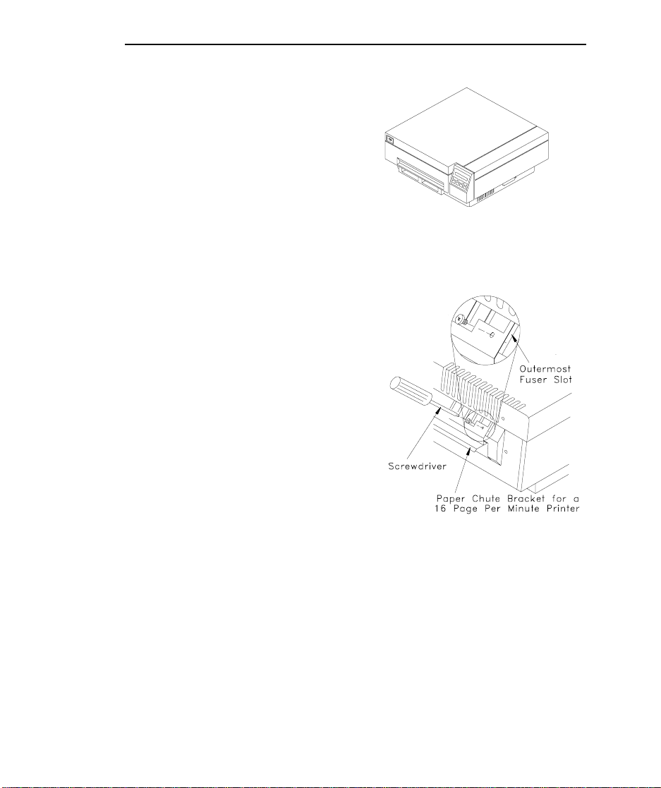
LaserMatrix printer,
proceed as follows:
For a 16 page per
minute printer, use the
two remaining screws
1
(the shorter,
/2-in.long, screws) to fasten
the paper chute support
bracket to the printer’s
plastic fuser cover, as
shown in the
illustration on the right.
When doing so, be sure
to hold bracket firmly
against the printer.
Make sure the screws
thread into the
outermost slots of the
fuser cover.
LaserMatrix Floor Model Stacker 9
PB0-C
16 Page Per Minute
LaserMatrix Printer
LB0-E3
9. Install the paper chute assembly onto printer:
a. With the top cover of the printer closed, insert
hooked tabs of paper chute support into outermost
Page 12
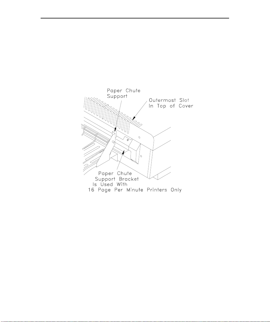
10 LaserMatrix Floor Model Stacker
slots at the top of the printer’s cover, as shown in
the next illustration.
For a 16 page per minute LaserMatrix printer, the
bail on the paper chute should rest on the paper
chute support bracket.
LB0-G1
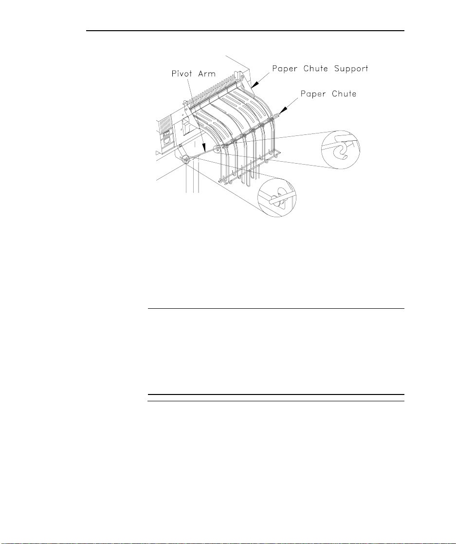
b. Pivot the paper chute slightly and then lift the free
end of the pivot arm, which is attached to the paper
chute, and insert it into slotted bracket on printer, as
shown in the next illustration.
Page 13
LaserMatrix Floor Model Stacker 11
LB0-F2
c. Slowly open top cover of printer to check that this
paper chute assembly is securely in place.
10. See Caution and Note below before installing control
cable, as follows:
! CAUTION !
Do not use a control cable if your printer requires a
paper motion sensor for automatic operation. (See the
table on Page 29.) If you use a control cable where the
table on Page 29 specifies a paper motion sensor, you
may damage printer electronics.
NOTE: Two types of control cables are provided with the
stacker for use with LaserMatrix printers built after May
23, 1994. With all other printers, use either the manual
mode switch, shown in the illustration on Page 13, or
install a paper motion sensor (Part No. LM1000A119).
The paper motion sensor, like the control cables provided,
turns on the stacker only when the printer prints. For
Page 14
12 LaserMatrix Floor Model Stacker
more information, see Parts & Accessories, beginning on
Page 27.
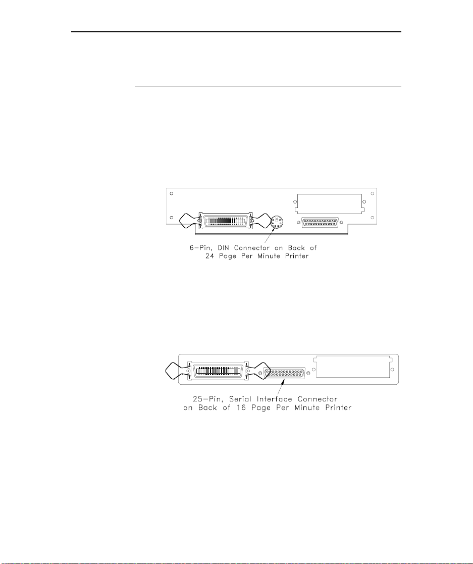
a. Do one of the following:
• For a 24 page per minute printer, connect the
cable with the round, 6-pin DIN connector to
printer’s back panel, shown in the following
illustration:
• For a 16 page per minute printer, connect the
cable with the D-shaped, 25-pin connector to the
printer’s back panel, shown in the following
illustration:
PB0-B
LB0-I2
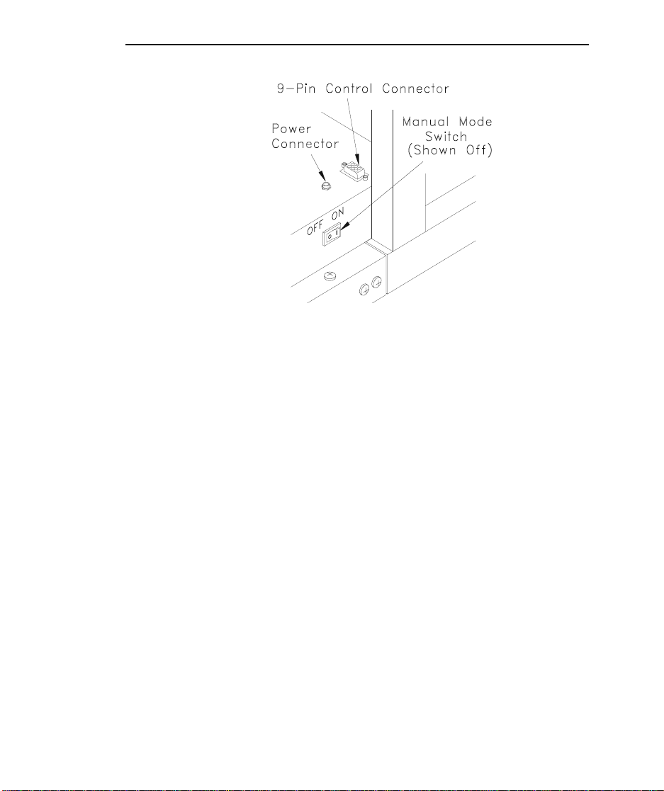
b. Connect the 9-pin end of the control cable to the
D-shaped, 9-pin control connector on the refolding
deck.
Page 15
LaserMatrix Floor Model Stacker 13
LB0-H1
Page 16
14 LaserMatrix Floor Model Stacker
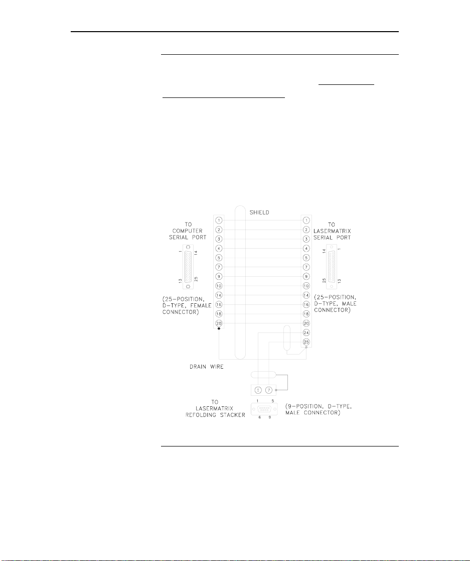
NOTE: The 25-pin connector on the printer is the
serial interface connector. If your 16 page per
minute LaserMatrix printer uses the serial port for
data input, you must connect a serial adapter
between the computer and stacker cables and the
25-pin connector on the printer. If you require a
serial adapter (Part No. LM1000A121), contact
Output Technology by voice or fax. See the phone
numbers at the front of this publication. Or make
your own from the wiring diagram below.
Serial Adapter Wiring Diagram
LB0-P3
Page 17
LaserMatrix Floor Model Stacker 15
c. Tighten screws on both connectors to secure cable.
d. Make sure manual mode switch on refolding deck is
off, as shown in the illustration on Page 13.
11. Insert connector on power supply cable into receptacle on
refolding deck. Connect power supply to a suitable
receptacle.
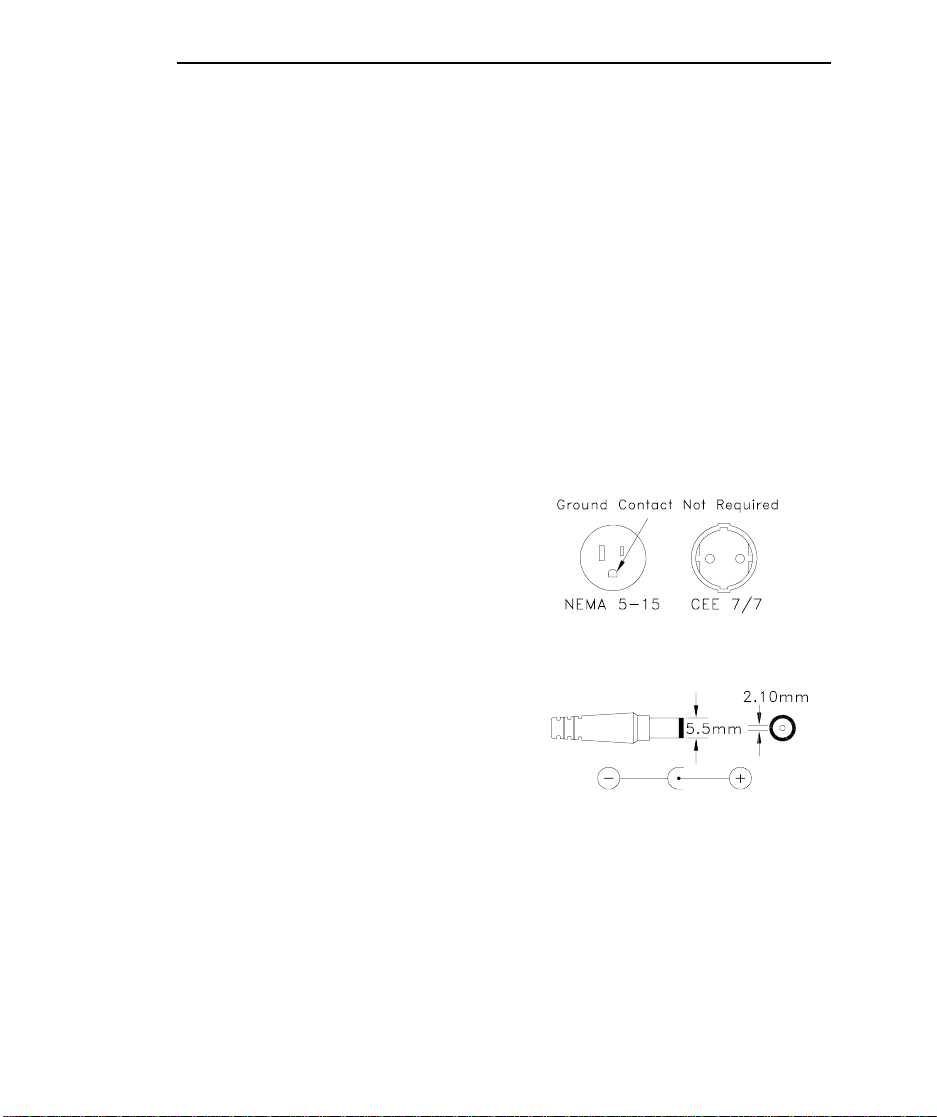
If your power source is other than 120 vac at 60Hz or 230
vac at 50Hz (or your receptacle is other than a NEMA 515 or a CEE 7/7, as shown in the following illustration),
you will need to purchase a class 2, regulated 12
vdc, power supply. The
power supply must be
capable of supplying 12
vdc at a minimum of 800
ma to the stacker via the
type of connector shown
in the following
illustration.
J1
12. If desired, use supplied cable ties to fasten control and
power cables to legs of stacker.
LB0-
Page 18

16 LaserMatrix Floor Model Stacker
13. Test manual mode by toggling the manual mode switch on
the refolding deck.
Both pairs of refolding coils should turn.
14. Test automatic mode for a LaserMatrix printer, as follows:
a. Turn on LaserMatrix printer.
b. Print a one-page print job.
When the LaserMatrix printer begins to print it will
start the stacker. The stacker will stop when the
LaserMatrix printer stops printing. If it doesn’t start
and stop automatically, you may need to install a
paper motion sensor for automatic operation. See
Parts & Accessories, Page 27.
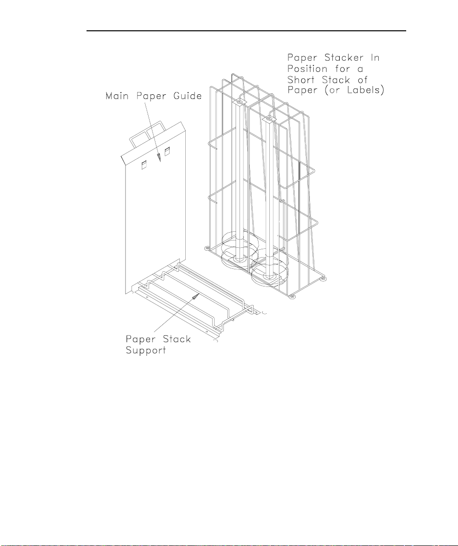
15. Slip the main paper guide onto the paper stack support, as
shown in the following illustration.
1
16. Slide this assembly, the paper stacker, between support
channels on refolding deck.
NOTE: The paper stacker assembly may be installed for either
right- or left-side access, whatever’s convenient.
1
For example, to print a summary page, be sure the printer is off line, then press the
key. After the printer displays “Print: Summary,” press
MENU
STORE
to print.
Page 19
LaserMatrix Floor Model Stacker 17
SETUP
SETUP
SETUPSETUP
LB0-K
For a Short Stack of Paper (or Labels) —
You’re all set. Use the paper stacker as shown in the
previous illustration. Continue with “Operation,” Page 20.
Page 20
18 LaserMatrix Floor Model Stacker
For a Tall Stack of Narrow Paper (or Labels) —
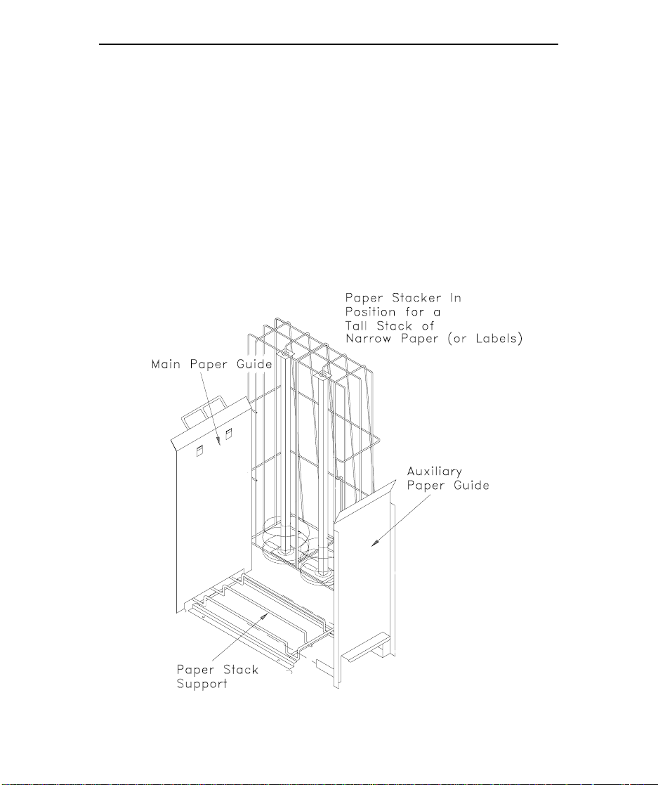
An auxiliary paper guide is provided to help control tall
stacks of paper or labels.
To install, slip auxiliary paper guide into paper stacker
channels so that it rests on top of paper stack support. Position
the auxiliary paper guide so that the distance between the two
sheet metal paper guides is
than the width of the fanfold paper or labels.
1
4
/
in. (approximately 6 mm) more
LB0-U
Page 21
LaserMatrix Floor Model Stacker 19
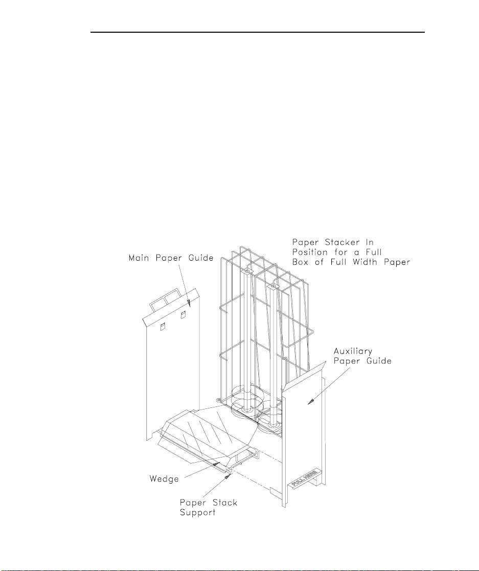
For a Full Box of Full Width Paper —
Fanfold paper tends to curl at the bottom and top
perforation folds. A wedge is supplied to counter this curl so
that the paper stacks evenly. The flexible platform attached to
the wedge allows the refolding coils to capture the first few
sheets of paper, which would otherwise miss the coils because of
the wedge. The flexible platform will bend down and out of the
way as the paper stack grows.
The auxiliary paper stack guide helps to control tall paper
stacks.
LB0-L
Page 22

20 LaserMatrix Floor Model Stacker
To install the wedge and auxiliary paper guide —
1. Snap wedge onto wireform of paper stacker.
It’s easiest if you snap in one side first and then slightly
compress the wedge to fit the other side.
2. Push the wedge against the main paper guide.
3. Slip auxiliary paper guide into paper stacker channels so
that it rests on top of paper stack support. Butt the
auxiliary guide against wedge.
With all parts assembled, the distance between the main
and auxiliary paper guides should be about 9
4. Continue with “Operation,” which follows.
OPERATION
OPERATION
OPERATIONOPERATION
1. Adjust position of paper stacker so that the face of the
main paper guide is approximately at edge of paper.
2. Now slide refolding units so that indicator marks at
bottom of units point to the proper perf-to-perf form
length marked on the deck.
The refolding units are mounted on a rack and pinion
mechanism so that they move as a unit. When you adjust
one, the other automatically adjusts to the same
complementary position.
NOTE: The positioning of the refolding units is critical
for fault-free performance.
3
/4 in.
Page 23
LaserMatrix Floor Model Stacker 21
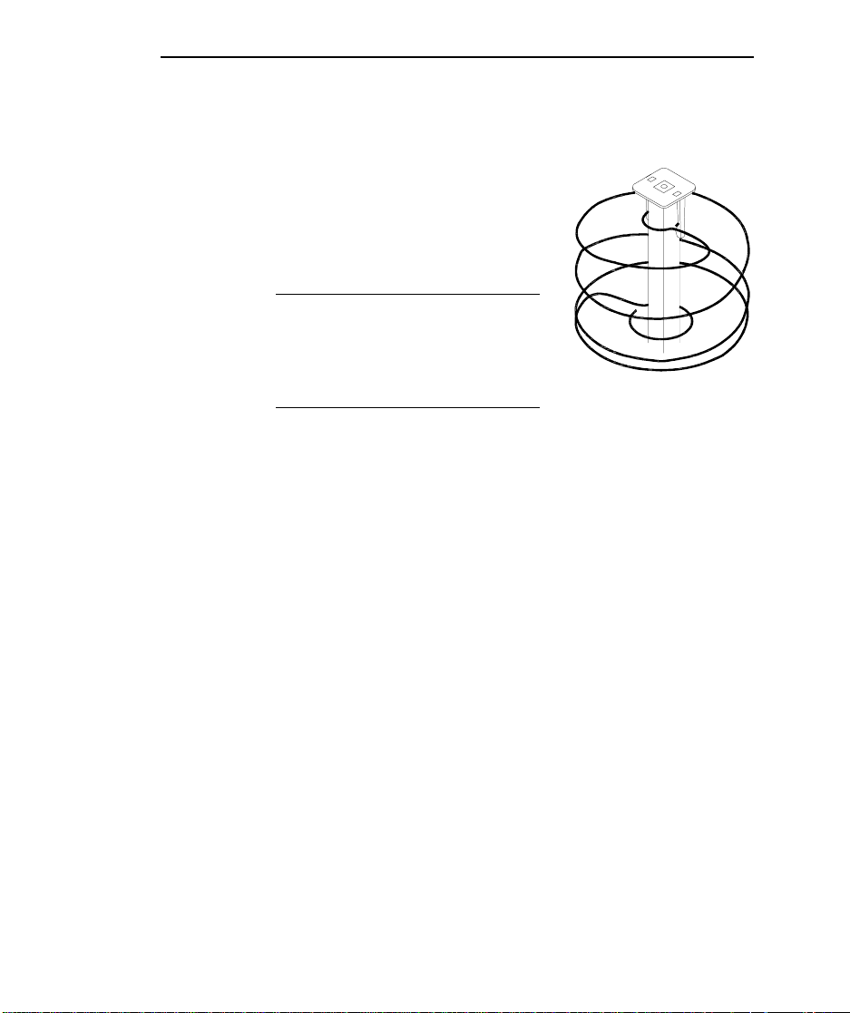
3. Check that the four coils are at the bottom of their risers.
The top caps of the risers
contain two plastic barbs to
capture the coils and suspend
them so that you can easily
remove the print job.
NOTE: Make sure to lower
coils again after every print job
so that they’re ready for the
next print job.
LB0-N
4. Open bail of paper chute.
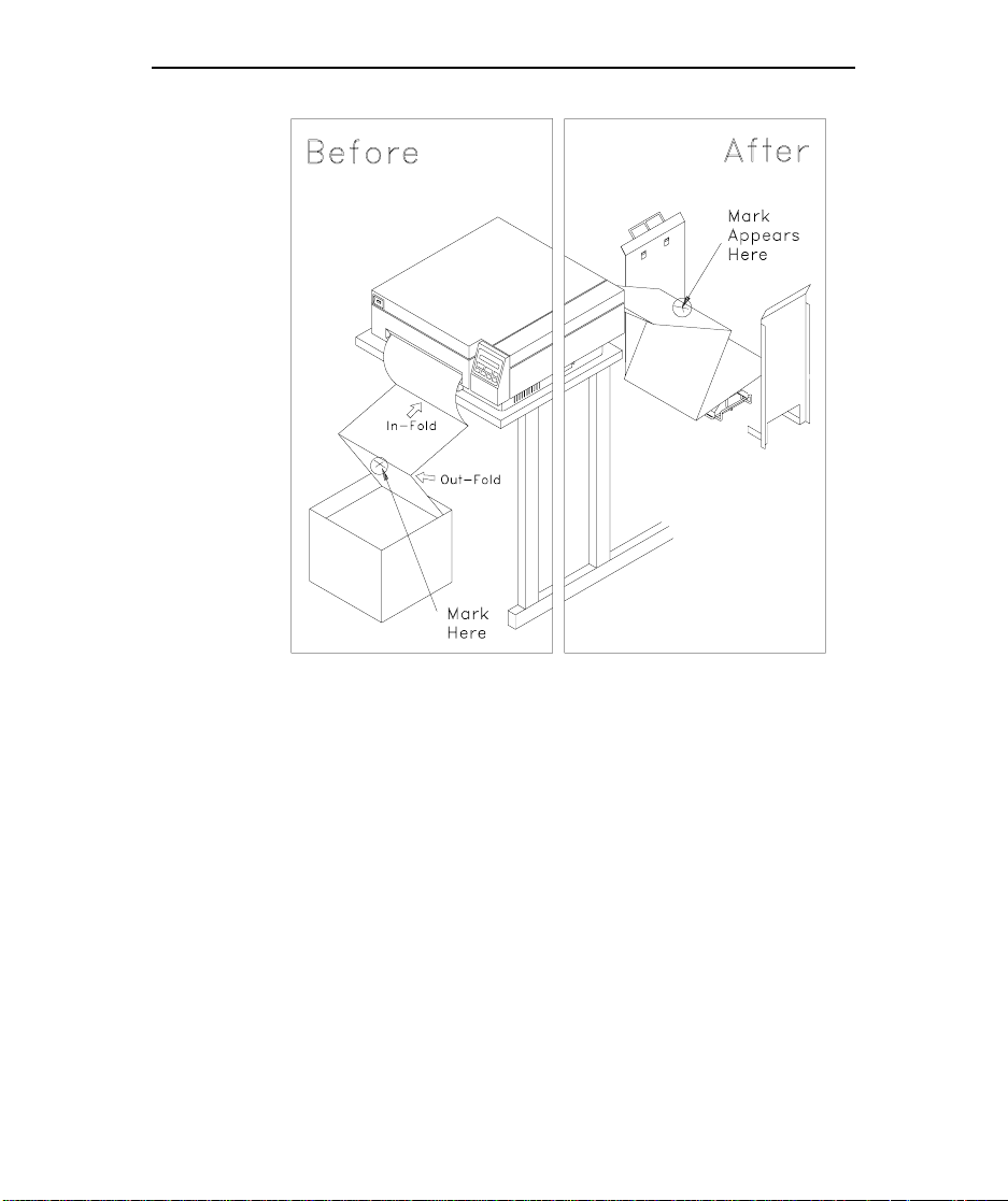
5. Make sure that the paper will stack on the stacker in the
same way it is in the box. To do this, mark an “X” on one
of the horizontal out-fold perfs at the paper entrance to the
printer, as shown in the following “Before” illustration,
and then use the printer’s control panel to form feed that
fold through the printer.
Page 24
22 LaserMatrix Floor Model Stacker
LB0-M1
6. At output of printer, make sure that paper feeds through
paper chute and then close the bail.
7. Again, use the printer’s control panel to advance the
paper. Continue until out-fold perf with mark is at bottom
of stacker.
8. Make sure the mark you made at the out-fold perf is not
lapped over, as would be the case of an in-fold perf. (See
the “After” illustration.)
Page 25
LaserMatrix Floor Model Stacker 23
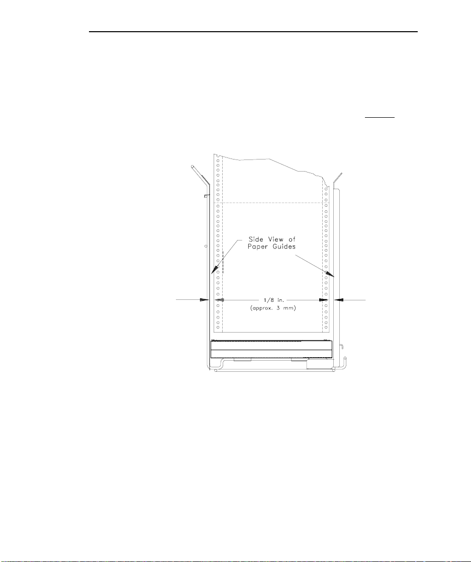
9. Adjust paper stacker, if necessary, so that paper falls in a
straight cascade from the paper chute to bottom of stacker.
The paper should be centered between the two pairs of
coils. Stacking works best if the paper stack is started
1
about
/8 in. (approximately 3 mm) from the paper
guide(s), as shown in the following illustration.
LB0-T
10. Begin printing.
11. If necessary, re-adjust paper stacker and/or refolding unit.
The paper should not drag or hang up on sheet-metal paper
guide(s), especially when you just begin a stack.
Page 26

24 LaserMatrix Floor Model Stacker
NOTE: Starting the stack
1
/8 in. from the guides is
important if you plan on a tall stack, and especially when
using lower-quality paper. The perfs of some fanfolded
paper are not always squared well with each other and so,
as the stack grows, it may tend to lean a little. If this
causes a problem, we recommend a different brand of
2
paper
.
12. When print job is done and you wish to retrieve your
printing, advance the last printed page past the paper chute
and then separate at the perf.
13. If you used the auxiliary paper guide, slide it out of the
deck channels.
14. Lift the refolding coils to the tops of their risers.
15. Use the handles on the paper stack support to slide out and
transport the print job.
Don’t use the flexible platform attached to the wedge of
the paper stacker for carrying the print job. If you do, you
might spill the paper stack. Use the built-in handles on the
paper stack support.
2
If stack-lean interferes with unattended performance, check for bad perforation
alignment. To test for perforation misalignment, turn the box of paper around on
the next print job and check if the stack tends to lean in the opposite direction. If it
does, change brand names. We recommend our own brand of paper (Part No.
LM1000C112) which is manufactured to exacting tolerances for consistent
performance.
Page 27

16. After removing the stack of paper, don’t forget to release
the coils so that they’re ready for the next job.
The LaserMatrix Floor Model Stacker will hold more than
the tallest box of continuous form paper. If you happen to
overfill the stacker with paper from more than one box,
the coils will compress at the top of their risers. Although
this won’t harm the stacker, you may find it inconvenient
when removing the print job. If you compress the coils to
their limits, the rest of the print job will not stack properly.
MAINTENANCE
MAINTENANCE
MAINTENANCEMAINTENANCE
Cleaning
LaserMatrix Floor Model Stacker 25
• For Paper Dust
• For Smudges, Dirt, etc.
with or without a little soap. You can use a mild
household cleaner like 409
, a large, soft, floppy brush works well.
, use a damp (not dripping) cloth
3
. But don’t allow water or
other cleaner to seep into the power or control connector
on the refolding deck, or into the drive mechanism of the
refolding unit.
! CAUTION !
Don’t use petroleum-based cleaners and solvents such
as lighter fluid, paint thinner, etc., which can damage
paint.
3
409
is a brand name of The Clorox Company.
Page 28

26 LaserMatrix Floor Model Stacker
Lubrication
The LaserMatrix Floor Model Stacker is lubricated for
life. Do not lubricate in any way.
TROUBLESHOOTING
TROUBLESHOOTING
TROUBLESHOOTINGTROUBLESHOOTING
When It Doesn’t Run —
Check the power supply and control cable.
When Only One Pair of Coils Turns —
One of the two motors has failed. Call one of the voice or
fax phone numbers listed on the back of the title page.
When It Doesn’t Stack Right —
• Check that the paper falls in a straight line from the printer
to the stacker. Make sure the paper stack support is
directly below and centered with the paper chute.
• In general, the stack should be centered front-to-rear and
side-to-side among the four coils.
• Check that the paper is not being refolded in the wrong
way. It should stack on the stacker like it was in the box.
• Use a better grade of paper. See Pages 27 and 28 for
ordering paper from Output Technology.
Page 29

P ARTS & ACCESSORIES
P ARTS & ACCESSORIES
P ARTS & ACCESSORIESP ARTS & ACCESSORIES
Customer Replaceable Parts
Customer replacement parts are listed below
order by phone or fax (phone numbers are listed inside the front
cover of this publication) have the serial number of your
LaserMatrix Floor Model Stacker handy. The serial number
appears on a label on the rim of the refolding deck. Also, have
your Visa or MasterCard number and expiration date ready.
Item Part No.
Paper Chute Support Bracket 001-00812-XX
Paper Chute Support 001-00745-XX
Paper Chute 001-00746-XX
Stack Support 001-00742-XX
Wedge (with flexible platform) 046-00878-XX
LaserMatrix Floor Model Stacker 27
4
. When you
Main Paper Guide 001-00797-XX
Auxiliary Paper Guide 001-00808-XX
Control Cable for 16 ppm Printer 020-00185-XX
Control Cable for 24 ppm Printer 020-00208-XX
Paper Motion Sensor LM1000A119
Power Supply (120 vac, 60Hz) LM1000CK100
Power Supply (230 vac, 50Hz) LM1000CK200
Adapter Cable for LM1000CK200
Operator’s Guide
5
Set of 6 Casters
4
Call for price.
5
2 locking, 4 nonlocking.
020-00016-XX
066-00452-XX
LM1000A126
Page 30

28 LaserMatrix Floor Model Stacker
Fanfold Paper (LM1000C112)
Fanfold paper manufactured for Output Technology is
optimized for use with the LaserMatrix printer and LaserMatrix
Floor Model Stacker. The paper is white, 24 lb, 8
fanfold paper (2000 sheets) which stacks to a height of about
11 in.
Paper Motion Sensor (LM1000A119)
The paper motion sensor is not required on LaserMatrix
printers manufactured after May 23, 1994. For these, the control
cable connecting the LaserMatrix printer to the LaserMatrix
Floor Model Stacker allows the LaserMatrix printer to turn on
the stacker only when the printer is printing.
LaserMatrix printers manufactured before May 23, 1994
require a paper motion sensor (Part No. LM1000A119) for
automatic
for automatic operation on other brands of continuous form laser
printers.
The paper motion sensor bolts to two threaded studs on
the underside of the paper chute support. A cable attached to the
sensor is connected to the D-type connector on the refolding
deck.
The table that follows lists part nos. of LaserMatrix
printers that require a paper motion sensor for automatic
operation. For the LaserMatrix printers, read the part no. on a
label on the back of the printer, below the paper exit. The last
two numbers of the part no. (XX) is the revision code for the
printer.
operation. Also, the paper motion sensor is necessary
1
/2 in. x 11 in.,
Page 31

LaserMatrix Floor Model Stacker 29
16 Page Per Minute LaserMatrix Printer
Paper Motion Sensor Effectivity
6
Is Paper Motion Sensor Required for Automatic
Operation?
LaserMatrix Printer
(Part No.)
048-00081-XX all
048-00082-XX all
048-00135-XX all
048-00136-XX all
048-00154-XX up to 048-00154-13 048-00154-14 & on
048-00156-XX up to 048-00156-10 048-00156-11 & on
048-00157-XX up to 048-00157-12 048-00157-13 & on
048-00158-XX up to 048-00158-09 048-00158-10 & on
048-00171-XX up to 048-00171-09 048-00171-10 & on
048-00178-XX up to 048-00178-09 048-00178-10 & on
048-00181-XX up to 048-00181-06 048-00181-07 & on
Yes
No
7
048-00182-XX up to 048-00182-06 048-00182-07 & on
048-00199-XX up to 048-00199-00 048-00199-01 & on
048-00200-XX up to 048-00200-00 048-00200-01 & above
6
You don’t need a paper motion sensor with a 24 page per minute LaserMatrix
printer.
7
You don’t need a paper motion sensor with these 16 page per minute LaserMatrix
printers.
Page 32

 Loading...