

Page 1
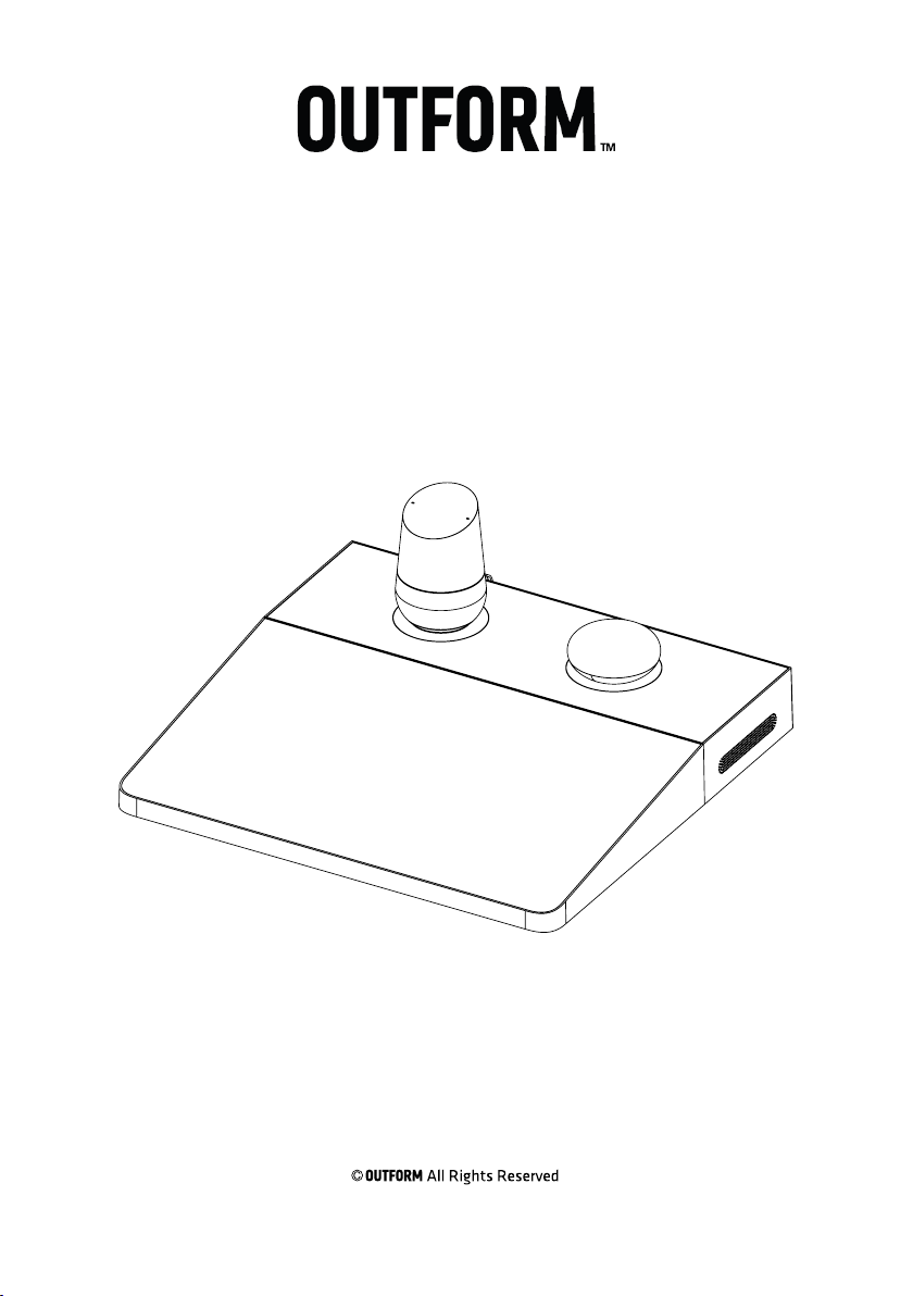
Interactive Riser
UIT421C-C01
User and Installation Guide
Page 2
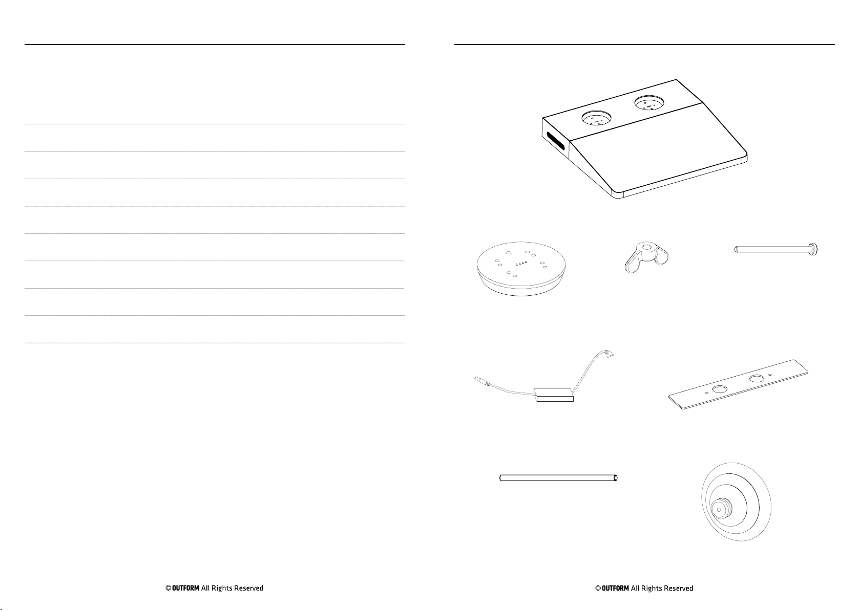
Table of Contents
Contents
Package Contents 3
Installing the Mini Risers 5
Installation Instructions 6
Rear View 7
Package Contents
Page 3
Interactive Riser
Updating the Joplin 8
Updating the Home 10
Setting the Default Volume on the Joplin and Home 11
Updating the System Software and System Reset 12
Functionality Test 14
Mini Riser x2 Butterfly Nut x2
PSU with AC cable
M5 Rod x2
Mini Riser Screw x4
Under Plate
Suction Cup
Page 3
Package Contents
Page 4
Installing the Mini Risers
Page 5
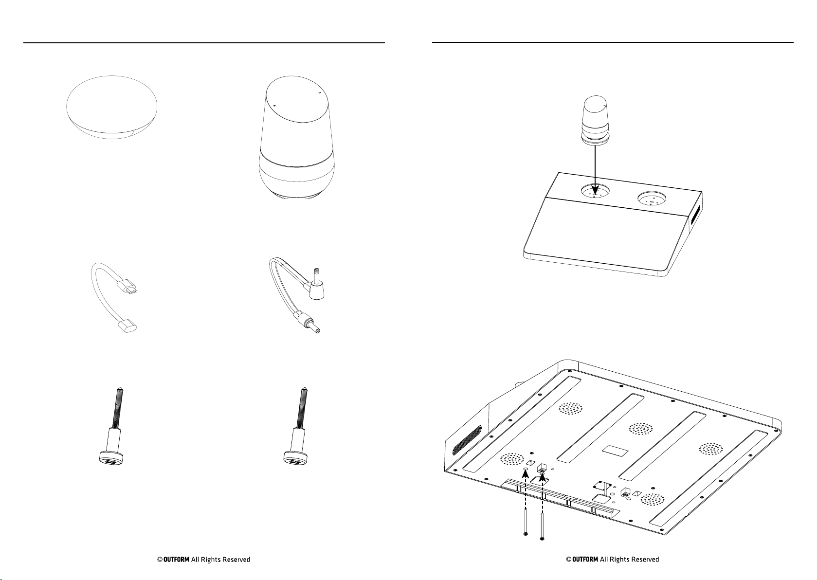
Joplin Home
Home CableJoplin Cable
Step 1. Install the mini riser with either the Home or Joplin into one of the
recesses in the interactive riser.
Step 2. Use the torque screwdriver to install 2x M4 through the base of the
interactive riser and into the mini riser securing it in place. Repeat steps 1
and 2 with the other mini riser.
Joplin Screw x2 Home Screw x2
Page 4
Installation Instructions
Page 6
Rear View
Page 7
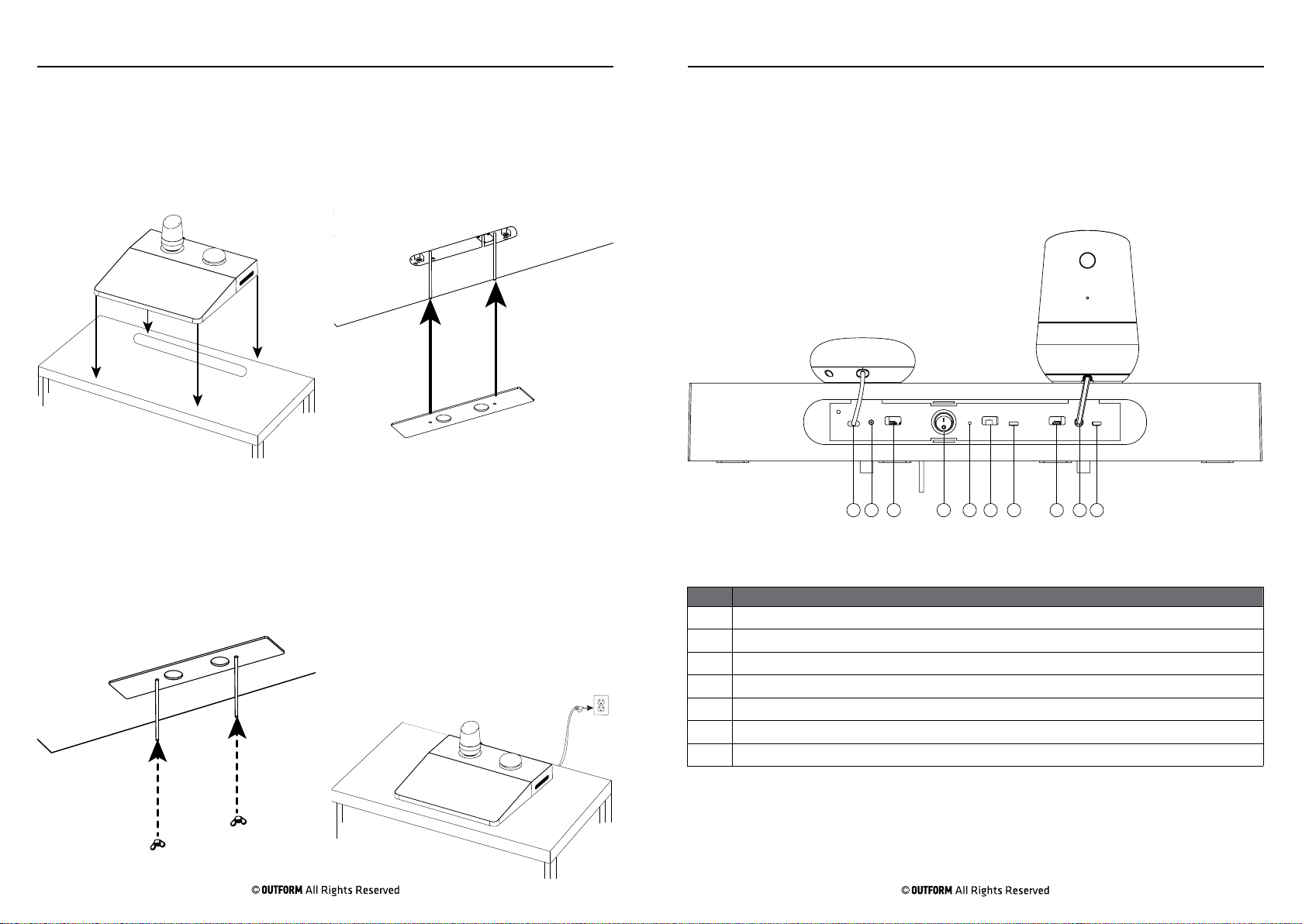
Step 1. Place the interactive riser
onto the display table. Make sure the
threaded rods, power cable and the
registration blocks go into the slot in the
table.
Step 3. Install the two butterfly nuts
onto the threaded rods. Tighten the
plate onto the underside of the table by
hand.
Step 2. Install the plate onto the
threaded rods until plate is flush with
the underside of the display table.
Step 4. Plug the power cable into the
nearest power socket. About 90 seconds
after the riser powers on, a home page
appers on the tablets screen for a few
seconds. DO NOT touch the screen
as the system is booting up. After the
home page disappears a static image
appears. Once you see the static image
,press the button that is displayed on the
screen.
The diagram below shows the dierent ports located in the back of the
display. The Joplin and the Home can be installed on either side of the riser
so there are 2x ports in which the Home and Joplin can be powered and
updated.
11 2 3 4 5 6 7 3 2
No. Description
1 Joplin Power Ports
2 Home Power Ports
3 Joplin/Home USB Update Port
4 Power Switch
5 System Reset Button
6 Update Screen Contents Port
7 Update System Software Port
Page 5
Updating the Joplin
Page 8
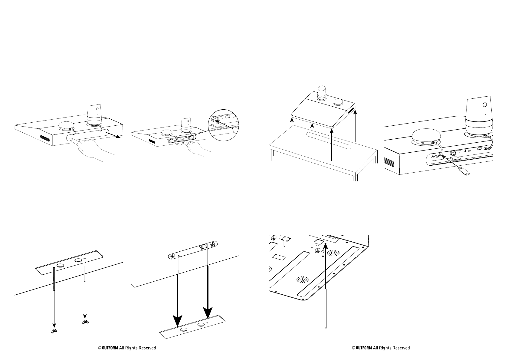
Updating the Joplin
Page 9
Step 1. Press the left side of the cover
inwards to lever the cover open.
Step 3. Remove the 2x butterfly nuts
by hand and put them to one side.
Step 2. Use your finger to power the
interactive riser o.
Step 4. Remove the plate and put it to
one side.
Step 5. Lift the display away from the
table.
Step 7. Insert a rod through the hole
located in the base of the display to
press the reset button on the riser. Press
and hold the reset button.
Step 6. Insert the USB into the correct
port (depending on what side the joplin
is installed).
Step 8. Power on the riser. In about
10 seconds 2x white LED’s on top of
the devices turn on. Release the reset
button once the 2x LED’s are on. After
a few seconds 4X white LED’s show.
After a few more seconds the LED’s go
blank. The flashing is in process. o
nce
the flashing is finished, one of the
following two things will happen:
1. If flashing is successful, all LED’s
will glow green. If flashing fails,
all LED’s glow red. If this happens,
restart the process. If red LED’s still
show then there is an issue with the
software on the USB. Reboot the
riser with the newly flashed sofware,
by powering o then back on.
Page 6

Updating the Home
Page 10
Setting the Default Volume on the Joplin and
Page 11
Step 1. Power o the riser.
Step 2. Insert the USB into the correct USB port (depending where the
Home is installed.)
Step 3. Press and hold the reset button on Home or Joplin. For the Home,
the button is on the back side. It is the only button on Home.
Step 4. Power on the riser and in about 10 seconds the 2x white LEDs turn
on. The LEDs are located on the top on both devices.
Step 5. Release the reset button once the 2x LEDs are ON. After a few
seconds 4x white the LED’s turn on. After a few more seconds, all LEDs go
blank. The flashing is in process.
Step 6. Once the flashing is finished, one of the following two things will
happen:
1. If flashing is successful, all LEDs glow green. If flashing fails, all LEDs
glow red. If this happens, retry the process.
2. If still red LEDs show, then there is an issue with the software on the
USB. Reboot the riser with the newly flashed sofware, by powering o then
back on.
Home
Note: There are 11 volume levels, the default is set at 6. The default volume cannot
be set lower than 6 but can be set higher than 6.
Step 1. Make an “M” gesture on the screen to access the Joplin and Home volume
controls.
Step 2. Adjust the volume to desired levels using the volume controls that appear
after the “M” gesture is made.
Step 3. To set the desired defualt volume for the Home and Joplin after adjusting
the volume to the desired level, hold the mute button located on the back of the
home for a few seconds or use the Reset button on the joplin.
Page 7
Updating the System Software and System
Page 12 Page 13
Reset
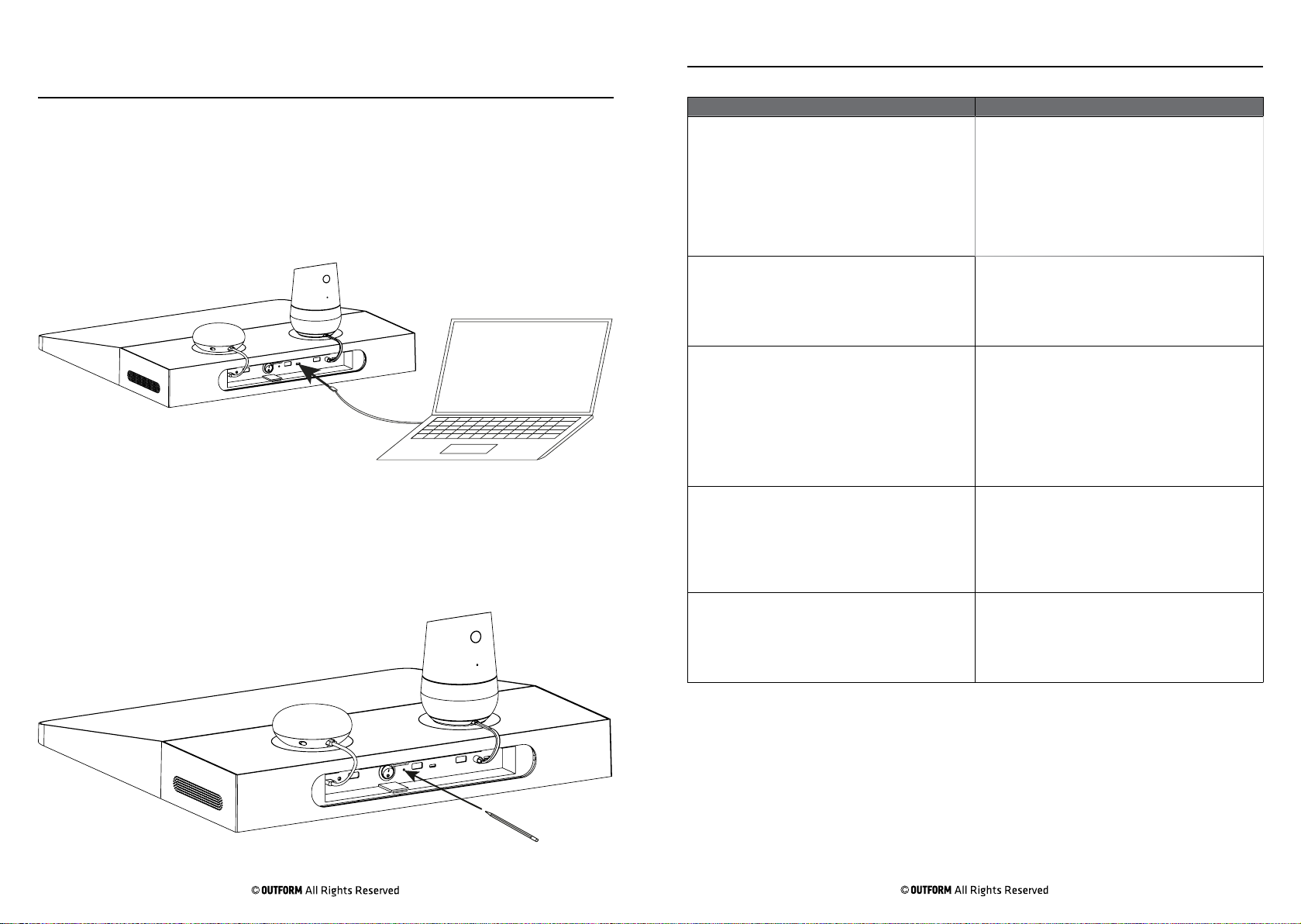
To update the system software plug a micro USB cabkle into the Micro USB
OTG port located on the rear of the display and plug the other end into a P.C.
Transfer the update from your P.C onto the riser, once transfer is complete
the Interactive riser updates automatically. Remove the Micro USB from the
OTG port.
If for any reason the system needs to be reset (for example the video freezes)
take o the rear cover from the display and insert a small rod or pencil
to press the system reset button. Hold down until the display resets then
release the reset button and replace the cover.
Troubleshooting Guide
Problem Solutions
After Installation the display has no power 1. Check to see that the PSU cable is inserted
securley into the power socket.
2. Check to see if power cable is connected to
the PSU correctly.
3. If still no power, reset the display.
4. If after resetting, the display does not work,
contact the number located on the back page of
this manual.
There is no sound coming from the tablet 1. Use your finger to draw a “W “on the screen,
this opens the volume control for the tablet.
Adjust the volume by sliding the slider right to
increase the volume and left to decrease the
volume.
There is no sound coming form the Joplin or
Home.
The Video loop does not play once the
installation is complete
The software has crashed 1. Restart the display by turning the power o
1. Make sure all cables connecting the Joplin and
Home to the display are secure and connected
correctly.
2. Use your finger to draw a “W” on the screen,
this opens 4x volume controls, 2x under each
of the Joplin and Home. Press the volume up
button under the Joplin or Home to increase the
volume.
1. Check to make sure that all power cables are
connected correctly and the devise is powered
on.
2. If power is connected and the video loop is not
playing open the settings. Press on the Android
icon labled Google Demo to play the demo loop.
and on.
2. If restarting the display does not work contact
the number located on the last page of this
manual.
Page 8

Functionality Test
1. Are all package accessories included in the package? Y/N
2. Are there are blemishes or damage to the display? Y/N
3. Does the display play the video loop automaticaly Y/N? If not refer to the trouble
shooting guide on page 13 in this manual.
4. Are the Home and Joplin synced to the video loop? Y/N
FCC Statement
This device complies with part 15 of the FCC rules. Operation is subject to
the following two conditions: (1) this device may not cause harmful
interference, and (2) this device must accept any interference received,
including interference that may cause undesired operation.
Changes or modifications not expressly approved by the party responsible
for compliance could void the user’s authority to operate the equipment.
NOTE: This equipment has been tested and found to comply with the limits
for a Class B digital device, pursuant to part 15 of the FCC Rules. These
limits are designed to provide reasonable protection against harmful
interference in a residential installation. This equipment generates uses
and can radiate radio frequency energy and, if not installed and used in
accordance with the instructions, may cause harmful interference to radio
communications. However, there is no guarantee that interference will not
occur in a particular installation. If this equipment does cause harmful
interference to radio or television reception, which can be determined by
turning the equipment off and on, the user is encouraged to try to correct
the interference by one or more of the following measures:
‐ Reorient or relocate the receiving antenna.
‐ Reorient or relocate the receiving antenna.
‐ Reorient or relocate the receiving antenna.
‐ Consult the dealer or an experienced radio/TV technician for help
important announcement Important Note:
Radiation Exposure Statement
This equipment complies with FCC radiation exposure limits set forth for an
uncontrolled environment. This equipment should be installed and operated
with minimum distance 20cm between the radiator and your body.
This transmitter must not be co-located or operating in conjunction with any
other antenna or transmitter.
Page 14
For additional assistance, call 1-800-966-5194
 Loading...