

Page 1

PV 8 Combiner
TM
PV 12 Combiner
User’s Guide
Includes Mounting and Installation Instructions
Page 2

2
Page 3

About OutBack Power Systems
OutBack Power Systems is a leader in advanced energy conversion technology. Our products include
true sine wave inverter/chargers, a maximum power point charge controller, system communication
components, as well as breaker panels, breakers, accessories, and assembled systems.
Notice of Copyright
FLEXware PV 8 Combiner FLEXware PV 12 Combiner Manual Copyright © 2008 All rights reserved.
Disclaimer
UNLESS SPECIFICALLY AGREED TO IN WRITING, OUTBACK POWER SYSTEMS:
(a) MAKES NO WARRANTY AS TO THE ACCURACY, SUFFICIENCY OR SUITABILITY OF ANY TECHNICAL OR OTHER
INFORMATION PROVIDED IN ITS MANUALS OR OTHER DOCUMENTATION.
(b) ASSUMES NO RESPONSIBILITY OR LIABILITY FOR LOSS OR DAMAGE, WHETHER DIRECT, INDIRECT,
CONSEQUENTIAL OR INCIDENTAL, WHICH MIGHT ARISE OUT OF THE USE OF SUCH INFORMATION. THE
USE OF ANY SUCH INFORMATION WILL BE ENTIRELY AT THE USER’S RISK.
Revision
March 2008
Contact Information
OutBack Power Systems
19009 62nd Ave. NE
Arlington, WA 98223
Phone (360) 435-6030
Fax (360) 435-6019
www.outbackpower.com
1
Page 4

TABLE OF CONTENTS
Warrranty Introduction ....................................................................................................................................................................3
Safety Instructions .............................................................................................................................................................................4
Requirements.........................................................................................................................................................................................5
FWPV-8 Combiner Features ..........................................................................................................................................................7
Sample FW-CBUS-8 (Bus Bar) Installations ...........................................................................................................................8
FWPV-8 Combiner ...............................................................................................................................................................................9
FWPV-8 Knockouts and Dimensions ....................................................................................................................................10
FLEXware PV-8 Combiner Wiring Sample (Circuit Breakers) .................................................................................11
Wiring Diagram ........................................................................................................................................................................12
FLEXware PV-8 Combiner Wiring Sample (Fuses) ........................................................................................................13
Wiring Diagram ........................................................................................................................................................................13
Fuse Holder Installation ................................................................................................................................................................14
FWPV-12 Combiner Features ....................................................................................................................................................16
Sample FW-CBUS-12 (Bus Bar) Installations .....................................................................................................................17
FLEXware PV-12 Combiner .........................................................................................................................................................18
FWPV-12 Knockouts and Dimensions .................................................................................................................................19
FLEXware PV-12 Combiner Wiring Sample (Circuit Breakers) ..............................................................................20
Wiring Diagram ........................................................................................................................................................................21
FLEXware PV-12 Combiner Wiring Sample (Fuses) .....................................................................................................22
Wiring Diagram ........................................................................................................................................................................23
Product Registration..................................................................................................................................... ..................................24
2
Page 5

Warranty Introduction
Dear OutBack Customer,
Thank you for your purchase of OutBack products. We make every e ort to assure our power
conversion products will give you long and reliable service for your renewable energy system.
As with any manufactured device, repairs might be needed due to damage, inappropriate use, or
unintentional defect. Please note the following guidelines regarding warranty service of OutBack
products:
• Any and all warranty repairs must conform to the terms of the warranty.
• All OutBack equipment must be installed according to their accompanying instructions and
manuals with speci ed over-current protection in order to maintain their warranties.
• The customer must return the component(s) to OutBack, securely packaged, properly addressed,
and shipping paid. We recommend insuring your package when shipping. Packages that are
not securely packaged can sustain additional damage not covered by the warranty or can void
warranty repairs.
• There is no allowance or reimbursement for an installer’s or user’s labor or travel time required to
disconnect, service, or reinstall the damaged component(s).
• OutBack will ship the repaired or replacement component(s) prepaid to addresses in the
continental United States, where applicable. Shipments outside the U.S. will be sent freight
collect.
• In the event of a product malfunction, OutBack cannot bear any responsibility for consequential
losses, expenses, or damage to other components.
Please read the full warranty at the end of this manual for more information.
3
Page 6

IMPORTANT SAFETY INSTRUCTIONS
SAVE THESE INSTRUCTIONS
The OutBack FLEXware PV-8 and PV-12 Combiners are listed by ETL as PV Combiners under the follow-
ing standards:
• UL 67, 11th Edition
• UL 1741, First Edition
• CSA C22.2, No.29-M1989
These enclosures meet Type 3R rainproof requirements when mounted vertically or leaning back to 14
degrees (3/12 pitch).
This enclosure is rated for up to 150VDC circuit breakers and up to 600VDC fuses.
Grounding Instructions – Each enclosure should be connected to a grounded, permanent wiring
system. For most installations, the negative battery conductor should be bonded to the grounding
system at one (and only one) point in the DC system. All installations must comply with all national
and local codes and ordinances. System grounding as required by the National Electric Code, ANSI
/NFPA 70-1996, or other appropriate codes is the responsibility of the system installer.
The equipment ground on FLEXware PV Combiner is marked with this symbol:
NOTE: Solar panels produce electrical current when light is present, even during overcast
weather. Do not wire from the array to the PV-8 or the PV-12 Combiner. Complete all
connections inside the combiner rst and then connect at the array.
OutBack Power Systems’ FLEXware
FLEXware is a convenient system of all-aluminum, powder-coated modular enclosures with associated
mounting hardware and stainless steel fasteners for housing OutBack power components. Our
indoor-rated enclosures and mounting plates o er secure and centralized installations for various
combinations of FX Series Inverter/Chargers, OutBack Charge Controllers, the OutBack HUB, MATE, and
Auto-Transformer, as well as breakers, bus bars, and balance-of-system components.
General Wiring and Installation Instructions
• Remove any necessary knockouts before securing the combiner to its mounting surface.
• Mount the combiner, securing it appropriately.*
• Slide the circuit breakers or fuse holders onto the DIN rail and lock in place.
• Secure the box lugs to the Combiner Bus Bar.
• Install the Combiner Bus Bar and secure it to either the fuse holders or the circuit breakers.
• Connect all wires to the fuse holders or circuit breakers and the box lugs, securing them
according to the listed torque values.
• Connect the wires to the solar array.
*FLEXware PV-8 and PV-12 Combiners are designed for weather-resistant outdoor installation when appropriate
fasteners and secure mounting surfaces are used. The back of each combiner has knockouts to accommodate
fasteners, U-bolts, or other hardware for secure attachment to a solid surface, including pole mounting. Both the
surface and the fastening hardware must be su cient to support the weight of the combiner.
4
Page 7

Requirements
• Use minimum 75
• Use only code-approved, appropriately listed circuit breakers, fuse holders, and fuses.
Maximum Fuse Rating 15 AMP , 600VDC
Maximum Circuit Breaker Rating 15 AMP, 150VDC
Total Maximum Current Rating PV8—120 AMPS DC PV12—180 Amps DC
Maximum Fuse Short Circuit Current 10kA
Maximum Breaker Short Circuit Current 10kA for 80V; 100A for 150V
Torque Data* for DC Negative Bus Bar Small Holes
0
C copper conductors.
WIRE SIZE TORQUE
AWG mm
14-10 2.1-5.3 20 2.3
8 8.4 25 2.8
6 13.3-21.2 35 4.0
2
in lbs Nm
Torque Data* for Box Lug
WIRE SIZE TORQUE
AWG mm
14-10 2.1-5.3 35 4.0
8 8.4 40 4.5
6-4 13.3-21.2 45 5.1
2/0-3 13.3-21.2 50 5.7
2
in lbs Nm
Torque Data* for DC Negative Bus Bar Large Holes
WIRE SIZE TORQUE
AWG mm
14-10 2.1-5.3 35 4.0
8 8.4 40 4.5
6-4 13.3-21.2 45 5.1
2/0-3 13.3-21.2 50 5.7
2
in lbs Nm
Torque Data* for Ground Bus Bar
WIRE SIZE TORQUE
AWG mm
14-10 2.1-5.3 20 2.3
8 8.4 25 2.8
6-4 13.3-21.2 35 4.o
2
in lbs Nm
DIN Rail Mounted Breaker and Fuse Holder Terminals are torqued 22 in lbs/2.5 Nm
*Data is also listed on the product label attached to the combiner box.
5
Page 8

6
Page 9

FWPV-8 Combiner Features
Removable front cover
• Accommodates circuit breakers or fuse holders using a
reversible* combiner bus bar
• Two output set screw lugs for parallel positive strings
capable of accepting 2/0 AWG/67.4 mm
2
output wires
• Comes with one ground bus bar and one negative bus bar
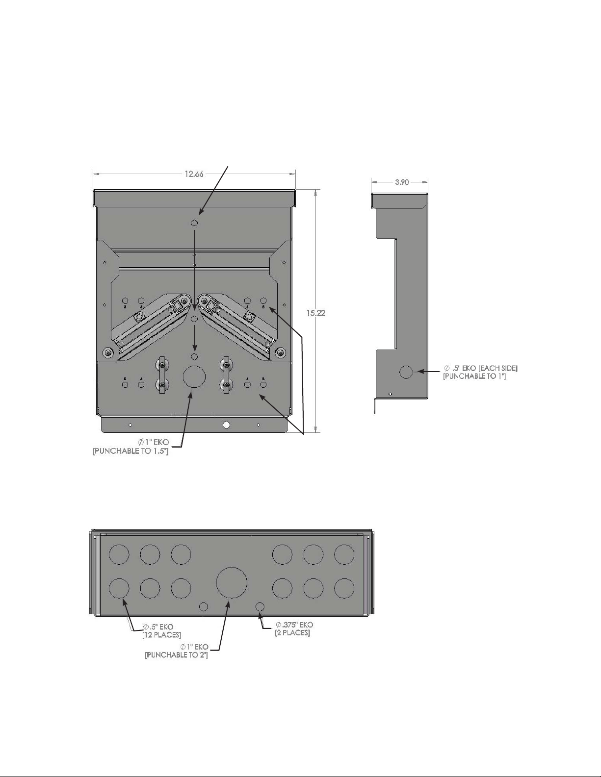
• 1” EKO bottom knockout punchable to 2” EKO
• 1” back knockout punchable to 1.5”
• Can be mounted on a 3”, 4” or 6” pole**
• Roof mountable at an angle down to 3-in-12 pitch (14
0
)
*NOTE: A combiner can use either circuit breakers or fuses
depending on the installation requirements, but it cannot use
both at the same time.
Each FWPV-8 comes with appropriate hardware for
securing either circuit breakers or fuses and their conductors.
Please see the separate FW-CBUS-8 Instructions for further
information.
**Requires fasteners not available from OutBack Power Systems
7
Page 10

Sample FW-CBUS-8 (Bus Bar) Installations
Circuit breaker installation using included bus
bar hardware
Bus bar hardware installed
Fuse holder installation
Optional DIN Rail
End Clamp
(FW-EC-DIN)
8
Page 11
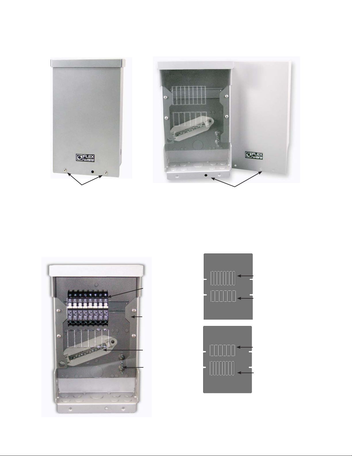
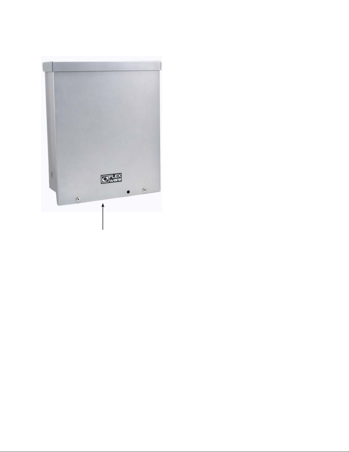
FWPV-8 Combiner
Two #12 sheet metal screws*
secure the combiner’s front cover.
A 7/16” lock hole accepts a
padlock to secure the cover.
Houses up to:
• Six “touch safe” OBFH fuse holders and knockouts for six input strings
• Eight DIN mount OBB circuit breakers
• Electrical knockouts capable of accommodating copper wire sizes from 2/0 to 14 AWG (67.4
2
mm
to 2.08 mm2)
Circuit Breaker
Optional circuit
Knockouts
breakers
Reversible, tinted
Fuse Knockouts
polycarbonate dead
front with breaker
and fuse knockouts is
secured with four #12
sheet metal screws*.
Negative Terminal
Fuse Knockouts
Bus Bar
Ground Bus Bar
Circuit Breaker
Knockouts
*Finish torque to 14 in-lbs
Dead front ips over
to accommodate fuse
holders or breakers
9
Page 12

Knockouts and Dimensions
FWPV-8 Combiner
Knockouts for at surface installation
10
Front View
Front View
Bottom View
Knockouts for 3”, 4” , and 6” U-bolts (pole mount installation)
Side View
Page 13

FLEXware PV-8 Combiner Wiring Sample (Circuit Breakers)
COMB(iner) Bus—combines all the PV array output “strings” or wiring at one
bus which connects to the OutBack Charge Controller(s); lugs can accept
cable sizes ranging from 2/0 to 14 AWG (67.4 mm2 to 2.08 mm2) copper wires.
Individual PV circuit
breakers (up to 15
amp/150 VDC) are
available from
OutBack.
Circuit breakers must
be secured to the
DIN rail and installed
ush against the
dead front mounting
ange.
Dead front mounting
ange.
DIN rail
Dead front
Negative Terminal
Bus Bar
Back chassis knockout
Individual array wiring enters through the bottom knockouts to stay weather resistant.
Ground Bus Bar
11
Page 14

BREAKERS
UP TO DUAL 2/0 AWG OUTPUT WIRES
POSITIVE COMBINATION BUS
TO CHARGE CONTROLLER OR INVERTER
PV
PV
PV
PV
+-+++- - -
PV
PV
PV
PV
+-+++- - -
PV
PV
PV
PV
+-+++- - -
PV
PV
PV
PV
+-+++- - -
GROUND BUS
PV
PV
PV
PV
+-+++- - -
+-+++- - -
PV
PV
PV
PV
GROUNDING ELECTRODE
PV
PV
PV
PV
+-+++- - -
PV
PV
PV
PV
+-+++- - -
PV NEGATIVE TBB
12
FWPV-8 with circuit breakers
Page 15
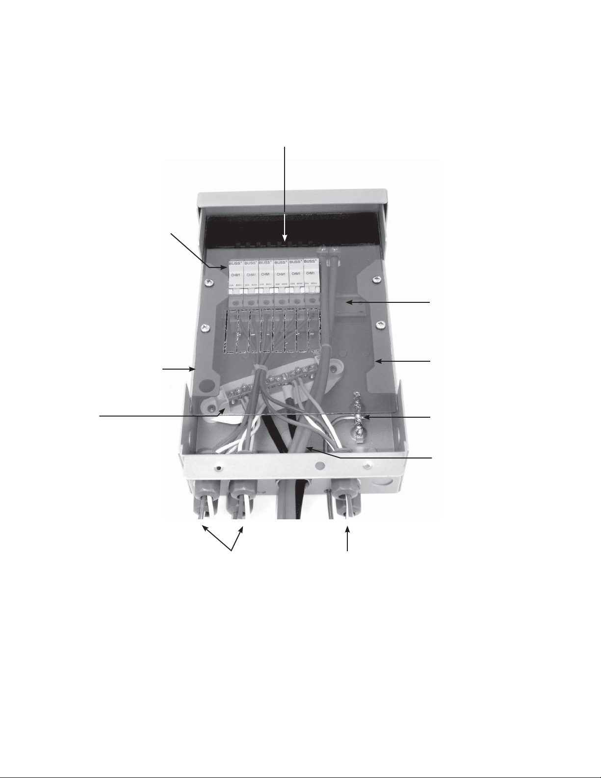
FLEXware PV-8 Combiner Wiring Sample (Fuses)
COMB(iner) Bus—combines all the PV array output “strings” or wiring at one
bus which connects to the OutBack Charge Controller(s); lugs can accept cable
sizes ranging from 2/0 to 14 AWG (67.4 mm2 to 2.08 mm2) copper wires.
Individual PV array fuses
and fuse holders (up to
15 amp/600 VDC) are
available from OutBack.
Fuse holders must be
secured to the DIN
rail and installed ush
against the dead front
mounting ange
DIN rail
Dead front mounting
ange
Negative Terminal Bus
Bar
Individual array wiring enters through the bottom knockouts to stay weather resistant.
Dead front
Ground Bus Bar
Back chassis knockout
13
Page 16

FUSEHOLDERS
WITH FUSES
UP TO DUAL 2/0 AWG OUTPUT WIRES
POSITIVE COMBINATION BUS
TO CHARGE CONTROLLER OR INVERTER
PV
PV
PV
PV
+-+++- - -
PV
PV
PV
PV
+-+++- - -
PV
PV
PV
PV
+-+++- - -
+-+++- - -
PV
PV
PV
PV
GROUND BUS
GROUNDING ELECTRODE
PV
PV
PV
PV
+-+++- - -
PV
PV
PV
PV
+-+++- - -
PV NEGATIVE TBB
14
FWPV-8 with fuses
Page 17

15
Page 18
FWPV-12 Combiner Features
Removable front cover
• Accommodates circuit beakers or fuse holders
using a reversible* combiner bus bar
• Four output set screw lugs for positive parallel
strings capable of accepting 2/0 AWG (67.4
2
mm
) output wires
• Comes with two ground bus bars and two
negative bus bars
• 1” EKO bottom knockout punchable to 2” EKO
• 1” back knockout punchable to 1.5”
• Can be mounted on a 6” or 8” pole
• Roof mountable at an angle down to 3-in-12
pitch (14
0
)
*NOTE: A combiner can use either circuit
breakers or fuses depending on the installation
requirements, but it cannot use both at the same
time. Positive combiner bus bars can be
combined per NEC 2008 standards.
Each FWPV-12 comes with appropriate hardware
for securing either circuit breakers or fuses and
their conductors (see next page).
16
Page 19

Sample FW-CBUS-12 (Bus Bar) Installations
Fuse holder installation using included bus
bar hardware
Circuit breaker installation
Optional DIN Rail End Clamps (FW-EC-DIN)
Bus bar hardware installed
17
Page 20

FLEXware PV-12 Combiner
Two #12 sheet metal screws* secure
the combiner’s front cover.
A 7/16” lock hole accepts a
padlock to secure the cover.
Houses up to:
• Eight “touch safe” OBFH fuse holders and OBF fuses and knockouts for eight input strings
• 12 DIN mount OBB circuit breakers
• Electrical knockouts capable of accommodating copper wire sizes from 2/0 to 14 AWG
(67.4 mm
2
to 2.08 mm2)
Combiner shown with
optional fuse holders
mounted to DIN rail.
Tinted polycarbonate
dead front with breaker
and fuse knockouts
secures with four #12
sheet metal screws*.
Negative Terminal Bus
Bars
Circuit
Breaker
Knockouts
Fuse
Knockouts
Fuse
Knockouts
Circuit
Breaker
Knockouts
*Finish torque to 14 in-lbs
18
Ground bus bars
Dead front ips over
to accommodate fuse
holders or breakers
Page 21
Knockouts and Dimensions
FWPV-12 Combiner
Knockouts for at
surface installation
Front View
Bottom View
Side View
Knockouts for 6” and 8”
U-bolts used in pole mount
installation
19
Page 22

FLEXware PV-12 Combiner Wiring Sample (Circuit Breakers)
COMB(iner) Bus Bars—combine all the PV array output “strings” or wiring at two
bus bars which connect to the OutBack Charge Controller(s); lugs can accept cable
sizes ranging from 2/0 to 14 AWG (67.4 mm2 to 2.08 mm2) copper wires.
Dead front
mounting
ange
DIN rail
Negative Terminal
Bus Bar
Back chassis
knockout
Circuit breakers
must be secured
to the DIN rail
and installed ush
against the dead
front mounting
ange
.
Individual PV
circuit breakers
(up to 15 amp/150
VDC) are available
from OutBack
Dead front
Negative Terminal
Bus Bar
Ground
Bus Bars
Individual array wiring enters through the bottom
knockouts to stay weather resistant.
20
Page 23

UP TO DUAL 2/0 AWG
OUTPUT WIRES
POSITIVE COMBINATION BUS POSITIVE COMBINATION BUS
TO CHARGE CONTROLLER OR INVERTER
BREAKERS
+-+++- - -
PV
PV
PV
PV NEGATIVE TBB
PV
PV
+-+++- - -
PV
PV
PV
PV
PV
+-++
+- - -
+-+++- - -
PV
PV
PV
PV
PV
+-+++- - -
+-+++- - -
PV
PV
PV
PV
PV
+-+++- - -
+-+++- - -
PV
PV
PV
PV
PV
+-+++- - -
+-+++- - -
PV
PV
PV
PV
PV
+-+++- - -
+-+++- - -
TO CHARGE CONTROLLER OR INVERTER
PV NEGATIVE TBB
PV
PV
PV
PV
PV
PV
PV
GROUND BUS
PV
PV
GROUNDING ELECTRODE
FWPV-12 with circuit breakers
PV
PV
PV
PV
PV
PV
PV
PV
PV
21
Page 24

FLEXware PV-12 Combiner Wiring Sample (Fuses)
COMB(iner) Bus Bars—combine all the PV array output “strings” or wiring at two
bus bars which connect to the OutBack Charge Controller(s); lugs can accept
cable sizes ranging from 2/0 to 14 AWG (67.4 mm2 to 2.08 mm2) copper wires.
Dead front
mounting
ange
DIN rail
Negative
Terminal
Bus Bar
Fuse holders must
be secured to the
DIN rail and installed ush against
the dead front
mounting ange.
Individual PV
array fuses and
fuse holders (up to
15 amp/600 VDC)
are available from
OutBack.
Dead front
Back
chassis
knockout
Individual array wiring enters through the bottom
knockouts to stay weather resistant.
NOTE: Please see page 15 for fuse holder installation information.
Negative
Terminal
Bus Bar
Ground Bus Bars
22
Page 25

UP TO DUAL 2/0 AWG
OUTPUT WIRES
POSITIVE COMBINATIONBUS POSITIVE COMBINATIONBUS
TO CHARGE CONTROLLER OR INVERTER
PV NEGATIVE TBB
PV
PV
PV
PV
PV
+-+++- - -
+-+++- - -
PV
PV
PV
PV
PV
+-+++- - -
+-+++- - -
FUSEHOLDERS
WITH FUSES
PV
PV
PV
PV
PV
+-+++- - -
+-+++- - -
PV
PV
PV
PV
PV
TO CHARGE CONTROLLER OR INVERTER
+-+++- - -
PV NEGATIVE TBB
+-+++- - -
PV
PV
PV
PV
PV
PV
GROUND BUS
GROUNDING ELECTRODE
FWPV-12 with fuses
PV
PV
PV
PV
PV
PV
23
Page 26

TM
Product Registration
us with some important information
Outback Power Systems Inc.
19009 62nd Ave. NE
Arlington, WA 98223
Please take a moment to register and provide
and return it to:
NOTE: Please complete one form for all installed FLEXware product.
FLEXware Product Registration
System Owner
Name: _______________________________________ Address: ________________________________________
City, State, Zip Code: ____________________________ Country: ________________________________________
Telephone Number: _____________________________ E-mail: _________________________________________
Installer
Company: ____________________________________ Contractor Number: _______________________________
Installer Address: _______________________________ Installer City, State, Zip: ____________________________
Installer E-mail: _________________________________
System
System Install/Commission Date: __________________
Sold by: ______________________________________ Purchase Date: ___________________________________
Please circle type of application:
O -Grid Grid-Interactive AC Coupled Backup Mobile
Please circle installed components:
FLEXware Enclosures and Mounting Components IOB Kits
FLEXware 250 FLEXware MP
FLEXware 500 AC FLEXware PV 8
FLEXware 500 DC FLEXware PV 12
FLEXware 1000 AC
FLEXware 1000 DC
The system is equipped with (circle one):
FW-X240 PSX-240 PSX-240-Relay
Please circle the three most important factors a ecting your purchase decision:
• Price • Product Reputation • Product Features • Reputation of OutBack Power Systems • Value
I am interested in receiving information concerning OutBack Power Systems products and
events (circle one):
Yes No
FW-IOB-S-120VAC
FW-IOB-S-230VAC
FW-IOB-D-120/240VAC
FW-IOB-D-120VC
FW-IOB-D-230VAC
FW-IOB-T-120/208VAC
FW-IOB-T-230/400VAC
FW-IOB-Q-120/240VAC
FW-IOB-Q-230VAC
24
Page 27

25
Page 28

19009 62nd Avenue NE
Arlington, WA 98223 USA
(+1) 360.435.6030
European Sales O ce
Barcelona, ESPAÑA
(+34) 600.843.845
www.outbackpower.com
900-0003-01-00 REV A
 Loading...