

Page 1

MATE
System Controller and Display
Installation and User Man ual
for the OutB ack MATE and MATE 2
1
Page 2

Warranty
Dear OutBack Customer,
ank you for your purchase of OutBack products. We make every eort to assure our power conversion
products will give you long and reliable service for your renewable energy system.
As with any manufactured device, repairs might be needed due to damage, inappropriate use, or unintentional
defect. Please note the following guidelines regarding warranty service of OutBack products:
• Any and all warranty repairs must conform to the terms of the warranty.
• All OutBack equipment must be installed according to their accompanying instructions and manuals with
specied over-current protection in order to maintain their warranties.
• e customer must return the component(s) to OutBack, securely packaged, properly addressed, and shipping paid. We recommend insuring your package when shipping. Packages that are not securely packaged can
sustain additional damage not covered by the warranty or can void warranty repairs.
• ere is no allowance or reimbursement for an installer’s or user’s labor or travel time required to disconnect,
service, or reinstall the damaged component(s).
• OutBack will ship the repaired or replacement component(s) prepaid to addresses in the continental United
States, where applicable. Shipments outside the U.S. will be sent freight collect.
• In the event of a product malfunction, OutBack cannot bear any responsibility for consequential losses, expenses, or damage to other components.
• Please read the full warranty at the end of this manual for more information.
About OutBack Power Systems
OutBack Power Systems is a leader in advanced energy conversion technology. Our products include true sine
wave inverter/chargers, maximum power point charge controllers, system communication components, as well
as breaker panels, breakers, accessories, and assembled systems.
Notice of Copyright
MATE System Controller and Display Installation and User Manual REV A © 2007 All rights reserved.
2
Page 3

Disclaimer
UNLESS SPECIFICALLY AGREED TO IN WRITING, OUTBACK POWER SYSTEMS:
(a) MAKES NO WARRANTY AS TO THE ACCURACY, SUFFICIENCY OR SUITABILITY OF
ANY TECHNICAL OR OTHER INFORMATION PROVIDED IN ITS MANUALS OR OTHER
DOCUMENTATION.
(b) ASSUMES NO RESPONSIBILITY OR LIABILITY FOR LOSS OR DAMAGE, WHETHER DIRECT,
INDIRECT, CONSEQUENTIAL OR INCIDENTAL, WHICH MIGHT ARISE OUT OF THE USE OF SUCH
INFORMATION. THE USE OF ANY SUCH INFORMATION WILL BE ENTIRELY AT THE USER’S RISK.
Date and Revision
September, 2007 REV A
Contact Information
OutBack Power Systems
19009 62nd Ave. NE
Arlington, WA 98223
Phone (360)435-6030
Fax (360)435-6019
outbackpower.com
3
Page 4

Contents
INTRODUCTION 6
MATE Specications and Features 7-8
Manual Setup 9
Installation 9-10
1 Basic Operation 12
Power Up 13
MAIN Screen 15
How to Read a MATE Screen 17
Screen Types 19
2 MATE Setup 20
Setup the MATE 21
Setting the Clock 22
Contrast Adjustment 24
Backlight Adjustment 25
3 MATE Communications Options 26
Communications Options 27
Communications Errors 30
Errors and Debugging 30
4 MATE Summary Screens 32
FX Summary Screen 34
Charge Controller Summary Screen 34
Summary Screen Options 34
5 MATE Status Screens 38
FX Status Screens 41
Charge Controller Screens 47
6 MATE Hot Keys 50
INV Hot Key 51
AC In Hot Key 52
7 Advanced MATE Menus 57
MATE Control Codes 58
e Advanced Menus 59
HBX Mode 60
Advanced Generator Mode 66
AGS Setup 67
Quiet Time 72
Weekday Start 73
Weekday Stop 74
Weekend Start 75
Weekend Stop 76
Voltage Start 77
Load Start 78
Must Run 81
Weekday Start 81
Weekday Stop 82
Weekend Start 83
Weekend Stop 84
Generator Exercise 88
Exercise Period 89
4
Page 5

Grid-Use Mode 91
Weekday Grid-Use Start 93
Weekday Grid-Use Stop 94
Weekend Grid-Use Start 95
Weekend Grid-Use Stop 95
MATE DEFAULTS 96
8 MATE Menu Map 100
Menu Structure 101
MATE Menu Guide 103
MATE Menus 105
MATE Menu Map Overview 119
APPENDIX 121
Troubleshooting 124
User Information and Settings 125
Warranty 126
Product Registration 127
5
Page 6
Introduction
e OutBack Power Systems MATE serves several functions:
• Displays and congures the system and its components—the FX Series Inverter/Charger,
the FLEXmax 80 Charge Controller*, and the FLEXnet DC
• Coordinates system operation, maximizes performance, and prevents multiple products
from conicting
• Permits exact adjustments of your power system through a series of convenient display
screens, which allow switching among dierent components, viewing the status of each and
changing settings
* MX60 Charge Controller—remote controls the AUX function and displays, but does not
control, all other functions
When connected to an OutBack HUB communications manager, a single
OutBack MATE can:
• Link to as many as ten FX Series Inverters/Chargers, OutBack Charge Controllers and
additional future OutBack Power System products
• Issue a global Bulk or EQ recharging command which includes the Charge Controller’s
charging function.
is manual will show step-by-step use of the OutBack MATE to best run a power system.
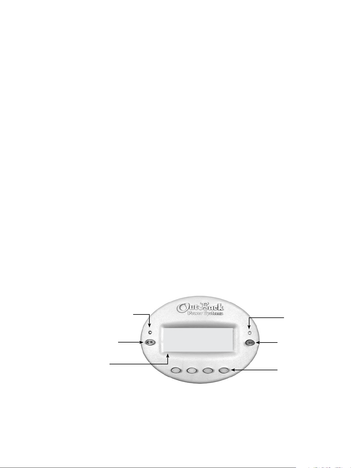
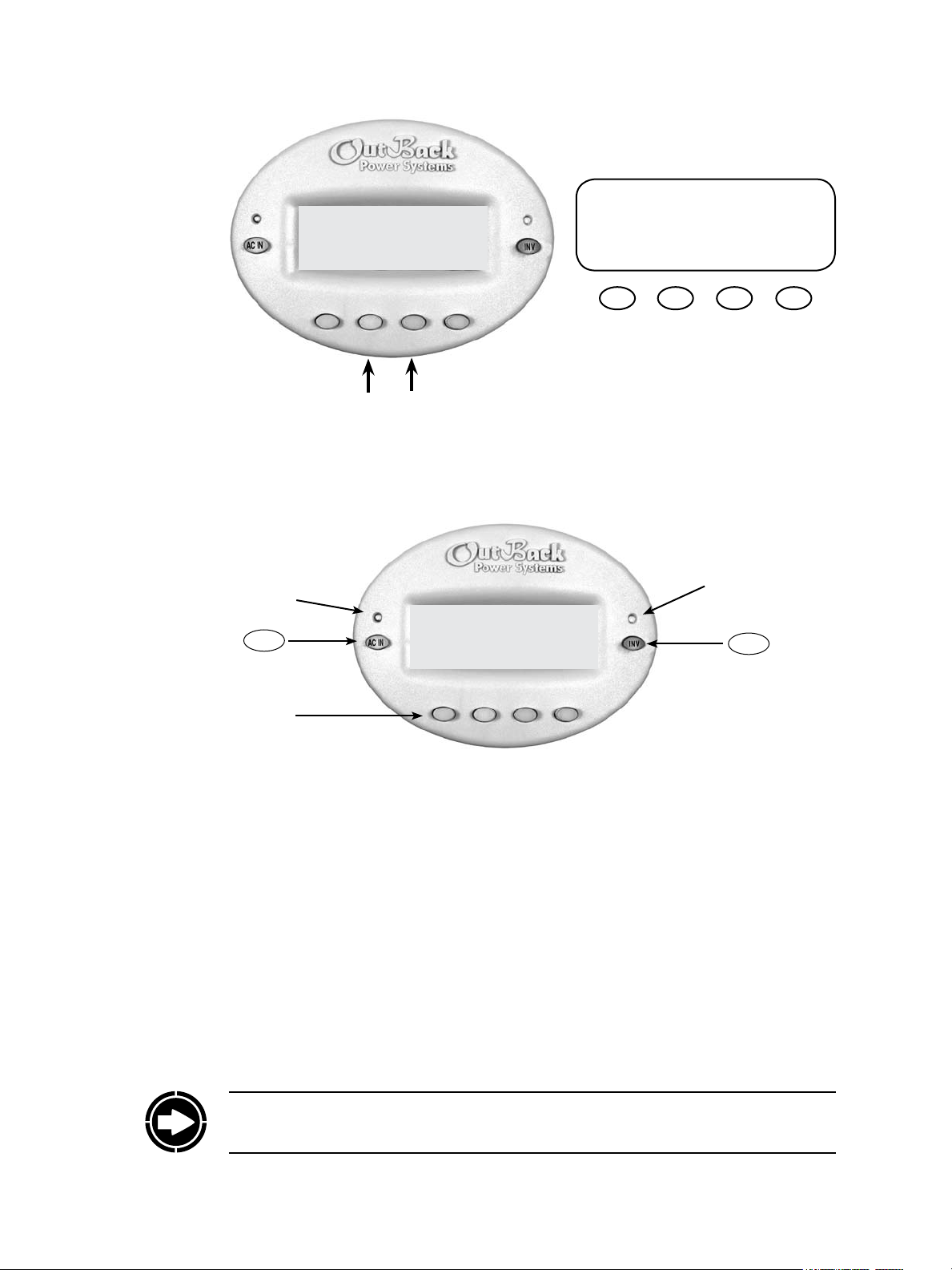
MATE At a Glance
Yellow Status Indicator,
AC Input LED
MAIN-------------------------
“Hot Key”
AC Input Button
LCD Display
Included with each MATE are one 50’
and one 6’ length of CAT5 cable.
1:35:04p
SUM STATUS SETUP ADV
Green Status Indicator,
Inverter LED
“Hot Key”
Inverter Button
Four “Soft” Keys
or Buttons to scroll the
menus and change values.
6
Page 7
MATE Specications
• Communication Protocol: proprietary OutBack multi-drop network
• Interconnecting Cable: CAT 5 (8 IATIA 518B) PC non-crossover network cable
• Maximum Cable Length Successfully Tested: 1000 feet (300 meters) of cable in an oce/
NOTE: Signal degradation can result if cable is run in conduit with AC wiring or in other
electronically “noisy” environments; these can aect the maximum length the cable can run
without incurring transmission errors.
• PC computer interface: RS232 Opto-Isolated DB9 serial communication port
NOTE: OutBack Power Systems does not produce or technically support any PC computer
soware programs compatible with its products. e following companies sell compatible
soware:
RightHand Engineering LLC (Winverter soware)
19310 226th Ave NE Woodinville, WA 98077
(425) 844-1291
Info@RightHandEng.com
commercial building
Intellact (WattPlot soware)
57 Mary Street, Alton, Ontario, Canada L7K 0E3
wattplot@intellact.ca
OutBack MATE Functions
Why use a MATE with your OutBack Power System FX Series Inverter/Chargers and Charge
Controllers? What exactly does it do?
A typical power system providing utility-supplied electricity requires very little from a user.
Other than ipping an occasional tripped circuit breaker back on due to an overload and
paying a monthly bill, there is little to monitor or adjust. A renewable energy (RE) system
requires more diligence and attention, including battery maintenance and setting various times
and voltages for the system to act eciently and economically.
Utility-supplied power is generated, monitored, and controlled by systems you neither see nor
maintain. An RE system requires some combination of inverter/chargers, batteries, charge
controllers, and an RE power source, oen including a generator, all of which need monitoring
and adjusting for optimum performance. e OutBack MATE provides a window to your
system and allows setting each OutBack component for its best and most ecient usage
according to your power needs and living conditions.
The MATE’s functions occur in to two general areas:
1. e display of information about or the status of dierent system components and actions
2. Enabling the user to control certain system functions, e.g., the times or the conditions
under which they will occur
7
Page 8

With the MATE, a user can know the system’s activity and conditions at any given time.
Sometimes, aer careful observations, a user might want to change the conditions or set points
which cause an action to occur.
What is a set point?
A set point is a condition, measurement, or baseline a user establishes in order for
something else to happen. A home thermostat oers a simple example. When predetermined
temperatures and times are set for weekdays and weekends, the thermostat signals to a
heating/cooling system to turn on at one time until a certain temperature is reached, maintain
that temperature, and nally shut o at a later time, usually during sleep hours to conserve
energy. Otherwise, the user would have to manually control the system. An outdoor light
connected to a timer turns on when its set point—a certain time of the night—occurs. You can
set various set points for your power system, such as when a generator turns on and shuts o,
using the MATE.
Among other functions, the OutBack MATE:
• Displays FX Series Inverter/Charger functions and allows the user to establish the
• Shows FX AC current and AC and DC voltage-related information including the source
• Instantly displays any FX or Charge Controller errors as well as the specic component
• Displays Charge Controller modes, programs the FLEXmax 80 Charge Controller and
• Will start a two-wire generator at pre-set times, including dierent settings for weekdays
• Displays all readings of the FLEXnet DC.
conditions—time of day or the voltage of the battery, for instance—that initiate or shut o
these functions.
(AC input, load, or batteries), the voltage levels of the batteries, and recharging voltages.
aected for easier troubleshooting.
allows control over its AUX function.
and weekends, as well as “exercise” periods for generator maintenance.
e MATE allows a user to view, monitor, and establish all the pertinent settings and values
that occur while the system is running. From time to time, these settings and values might be
adjusted as components are added or upgraded, electrical loads increase, or patterns of usage
change. Making these adjustments using the MATE is similar to adjusting any number of
electronic devices we all use every day, such as a clock radio whose wake-up time and stations
are pre-set.
Programming the start and stop times for dierent sources of energy (when to use gridsupplied power, stored battery power, or generator-supplied power) and determining the
frequency and duration of battery recharging are highly recommended with any RE system.
Many settings are based on battery voltage. Certain voltages, for example, will trigger battery
recharging (a low voltage, as recommended by the battery manufacturer) while others stop
recharging (a high voltage value, also recommended by the battery manufacturer). e
OutBack MATE accommodates a wide range of time-based and voltage-level functions and
conditions for maximum control of your power system while working through the FX Series
Inverter/Chargers and OutBack Charge Controllers.
As you go through the manual, start with the simple functions, such as setting the system’s
clock and calendar, to familiarize yourself with the OutBack MATE’s feel and capabilities.
While using your system, you might change settings from time to time depending on the
season of the year and the cost of grid-supplied power during peak and o-peak hours. For
additional information and discussion on the OutBack MATE, please go to
www.outbackpower.com and join our forum discussions.
8
Page 9

Manual Setup
e MATE is a micro-computing device which means it is less powerful and smaller in size
than a personal computer. A user will oen scroll through a series of MATE screens in order
to view the system status or change system conditions. is manual will show all the MATE
screens and tell what they do.
• Chapters 1-5: setting basic items and display options (when, how, and what you want
to view) with the “so keys,” enabling the user to get around the MATE and change its
settings.
• Chapters 6-7: changing the settings of MATE specic critical functions such as battery
recharging (HBX), generator usage (AGS), and using grid-supplied power (Grid Use
modes).
• Chapter 8 and the Appendix: lists and explains all the MATE menus. Some functions are
not MATE-specic functions and are placed at the end of the manual for easy searching.
Values for MATE specic functions, such as FX or OutBack Charge Controller specic
functions, are covered in their respective manuals.
The MATE displays three kinds of screens:
• Screens pertinent to the MATE’s own functions, such as its clock and the appearance of its
displays
• FX function screens which deal with its inverting and charging processes
• Screens showing Charge Controller modes and status
Installation
Although the MATE displays values and functions for the FX and OutBack Charge Controller
(shown as “CC” on the screens), the values reside within the components themselves.
The OutBack MATE:
• Designed for surface mounting in an indoor location, just below the eye level of a typical
user (the MATE 2 is designed for recessed installation, requiring a 5 1/2” X 4” opening to
be cut in a wall and four drywall screws or other fasteners to secure it)
• Readability of the display is aected by direct sunlight
• Connects to other OutBack devices using standard non-crossover CAT5 or CAT5e cable
• Has voltage less than 30 VDC and is thus considered a “limited energy circuit” normally
requiring no conduit (consult your local inspector for specic installation requirements)
NOTE: e MATE is shipped with (1) OBCAT-50 and (1) OBCAT-6 CAT5 cables with the
correct RJ45 connectors already installed. Longer (up to 1000’) or shorter cables can be
purchased (at home improvement and computer stores) pre-made or custom length cable
can be made on site. Follow the cable manufactures’ instructions when choosing connectors,
punch-down tools, and crimping tools. Incorrect crimping or handling of CAT5 cable can
negatively aect the operation of the MATE. CAT5 cable is not as robust as standard house
wiring and must be handled carefully. Avoid kinking the cable or tearing its outer sheathing.
Use plastic stand-o cable staples, J-hooks, or cable trays to support long runs of CAT-5 cable.
Do not splice cables. Cable runs must be protected and runs must be in approved conduit and
not exposed to the weather.
9
Page 10
DCfl‡AC ……………….0.0 kW
AC Load …. ……………………..
Buying ………………………….
Battery …………….…14.4V
To Install the MATE:
• Install all other OutBack components rst.
• Run the CAT 5 cable from the source (HUB, FX or Charge Controller) to the MATE’s
• If connecting a computer to the MATE or MATE2, run a serial cable from the computer to
• Unsnap the MATE’s back plate and nd the four screw holes. If a MATE2 version is used,
• e MATE and MATE2 are designed for easy wall mounting using appropriate fasteners
• Power up every OutBack device connected directly or indirectly (through the HUB) to the
• If installing the MATE, snap the MATE onto the back plate and push any excess cable back
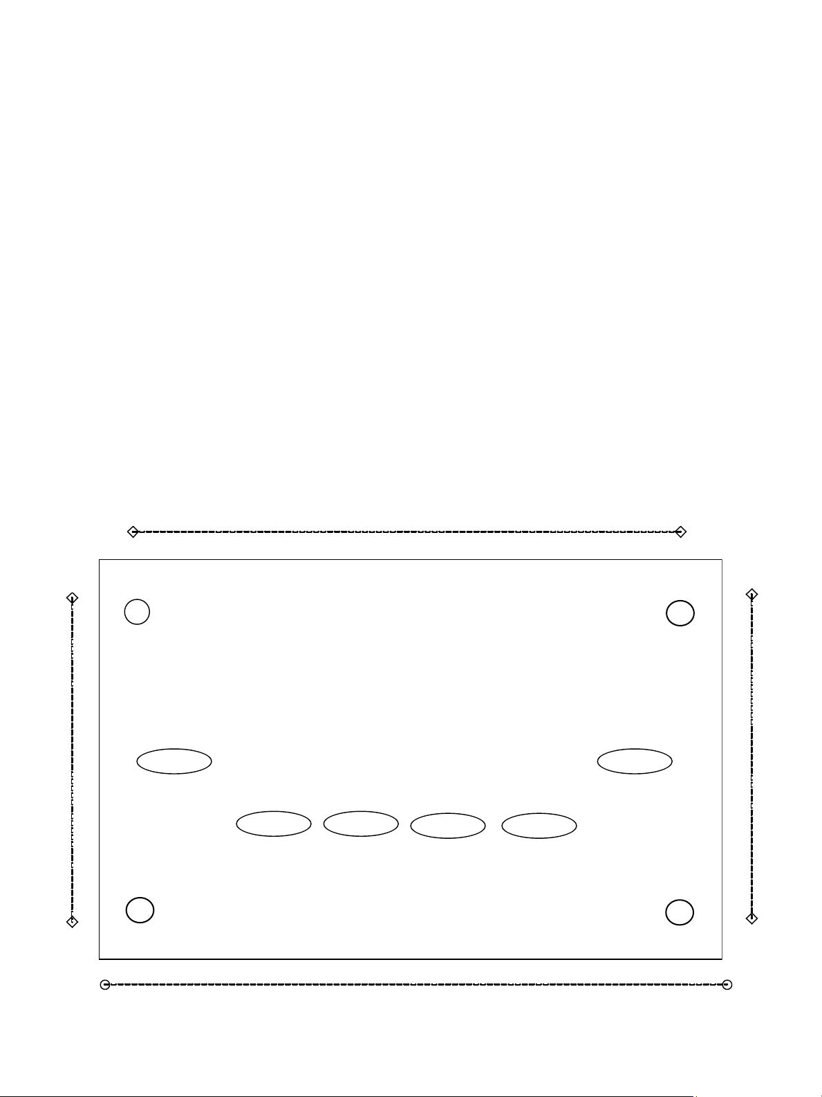
MATE2 Dimensions
location. Connect the CAT5 cable to the source but not to the MATE just yet.
the MATE’s location, but do not connect the cable at this time.
the back cover need not be removed.
(molly bolts, screws, etc.).
MATE and then connect the CAT5 cable to the jack and, if used, the computer serial cable
to the RS-232 port, on the back MATE or MATE2.
into the wall. If installing the MATE2 version, secure its four corners to the wall.
5” between screw holes
4 ½”
3 ½” between screw holes
10
6 1/4”
Page 11

11
Page 12

1 Basic Operation
12
Page 13
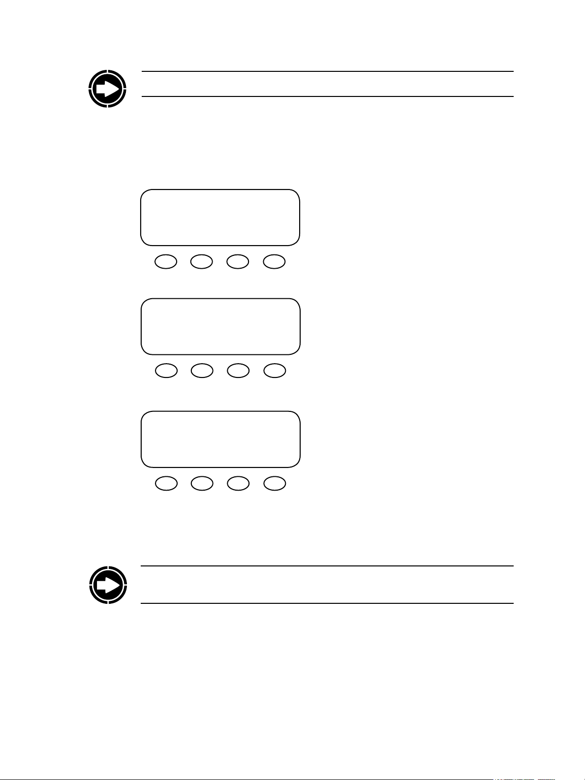
Power Up
NOTE: For a viewing of all MATE screens, please see pages 105-118 at the end of this manual.
A soon as the MATE cable is plugged into a powered OutBack product, the MATE itself will
power-up and display several information screens.
G’day Mate
(C) 2007
OutBack
Power
Systems
Version
Code a.aa
Serial #xxxxxxxx
Screen EE b.bb
First Screen
Second Screen
ird Screen
t “Code” dictates the MATE’s operation and
features*
t Serial #” matches the bar code sticker inside
the MATE on its circuit board
t “Screen EE” refers to the MATE’s menu system
13
NOTE: you will need the code and serial number of the MATE if contacting OutBack Power
Systems regarding its operation
*For an explanation of the diering code versions, see the MATE rmware revisions topic under MATE
Release Notes on the OutBack Power Systems User Forum found at: http://www.outbackpower.com/
forum/viewtopic.php?t=211
Page 14
Searching for Devices
FX Found
Searching for Devices
CC Found
Fourth screen (one of the following):
t e MATE found an FX Series
Inverter/Charger
t e MATE has found a Charge Controller
Searching for Devices
HUB Found
Port Assignment
1> FX 2> FX 3> CC 4> CC
5> 6> 7> 8>
9> 10> 2M>
Searching for Devices
No Devices Found
t e MATE has found the HUB
t Port Assignment screen follows the HUB
Found screen
t Each Port used will show its connected
component.
t e MATE has not found an OutBack
product
14
Page 15
MAIN Screen
No Device Found
Would you like to Retry?
YES NO
NOTE: If the MATE does not nd the connected device, refer to page 124, Troubleshooting
e MAIN screen appears aer the MATE detects
MAIN---------------------------------
12:17:04P
SUM STATUS SETUP ADV
the HUB (and any devices connected to it) or
detects a single device if a HUB is not in use. e
MAIN screen is always the same with the exception of the time display. At the bottom of the
MAIN screen are the four so key commands.
<SUM>
<STATUS>
<SETUP>
<ADV>
SUMMARY shows the direction and amount of
power ow in regard to inverting, charging, selling, and/or pass through. It also shows the voltage
of the battery.
e STATUS screen is the rst step in viewing
the status of either the OutBack Charge Controller or FX Series Inverter/Charger and any of their
meters and conditions.
e SETUP screen leads to additional screens
showing some common set points and parameters
of either the MATE or an FX Series Inverter/
Charger. ese screens allow adjustments to such
features as the MATE’s clock and background
lighting or whether the power input to the FX is
coming from a grid or a generator.
e ADVANCED screen leads to screens for the
FX Series Inverter/Charger, the OutBack Charge
Controller, and the MATE itself that allow for
changing each component’s advanced settings.
15
Page 16
Navigation
MATE Buttons
Press the rst two so keys from any
screen to return to the MAIN screen.
MAIN---------------------------------
MAIN---------------------------
12:17:04P
1:35:04p
SUM STATUS SETUP ADV
is section of the manual will cover how to use the buttons on the MATE to navigate the
menus.
SUM STATUS SETUP ADV
Yellow Status Indicator,
AC Input LED
MAIN---------------------------
AC In
Hot Key
Soft Keys
Six buttons or keys navigate the MATE and change its settings:
HOT KEYS
t Two FX dedicated “hot” keys are
labeled AC IN and INV.
t Pushing the INV hot key will
return to its “hot” screen to control
the FX inverting function.
t Pushing AC IN will return to the
rst of four AC input “hot” screens.
Repeated pushing cycles through
the four AC input screens.
t A beeping noise is made every time
a hot key is pushed.
1:35:04p
SUM STATUS SETUP ADV
SOFT KEYS
t Each so key corresponds to the word on the
screen directly above it unless you are on the
Summary screen.
t e so keys navigate the menus (<UP>,
<DOWN>, <NEXT>, <BACK>, or <TOP>).
t ey can change settings (<OFF>, <AUTO>,
<ON>, <INC> to increase values and <DEC>
to decrease values).
t e so keys perform other functions
depending on the individual menu screen.
t As with the hot keys, a beeping noise occurs
every time a so key is pushed.
Green Status Indicator,
Inverter LED
INV
Hot Key
16
NOTE: Pressing and holding the two lower le keys at the same time will always bring up the
MAIN screen. Pressing one key sooner than the other may lead to a dierent screen.
Page 17
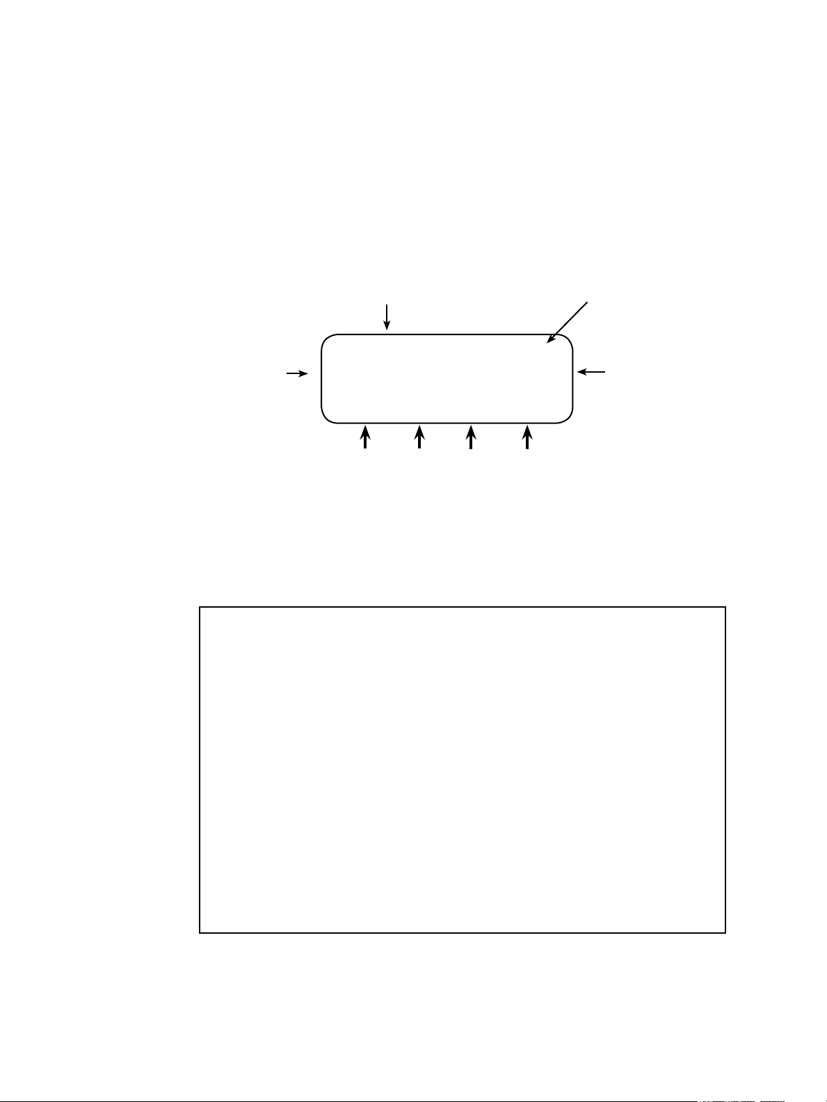
How To Read a MATE Screen
MATE screens will either show values that can be changed or navigate to value screens. e
information on the MATE’s screen is segregated by type or task and distinguished by location
on the screen and the choice of lowercase or uppercase letters. Occasionally it can be misread
by a user. e following example is shown for clarication.
Top line: where you are in the system
and what HUB Port you’re viewing
HUB Port
Left side: shows a
condition, value label,
system feature, or
measurable event
STATUS/FX/METERS----------P01
output 122 VAC
voltage
DOWN UP TOP PORT
Bottom line: soft key commands allowing the
user to change screens or alter a condition,
feature, or event or change ports if using a HUB.
Right side: status,
setting, or measure
of value for whatever
appears on the left side
Soft Key Related Abbreviations
ADV - Advanced INC - Increase
AGS – Advanced Generator Start INV - Inverter
AUX – Auxiliary Output MIN - Minutes
BATT – Battery PG1, PG2, PG3, PG4 - Page One, Page Two, etc.
CAL – Calibration RSET – Reset
CHGR – Charger SETP – Setup
CNT - Contrast SRCH – Search
COMM – Communication STAT – Status
DEC - Decrease SUM or SUMRY - Summary
DISCON – Disconnect TMRS - Timers
EQ – Equalize WARN – Warning
GEN – Generator P01—Master FX
HBX – High Battery Transfer PO2, PO3, etc. - Slave FXs
17
Page 18
t LOCATION—the top line, STATUS/FX/METER-----P01 (the HUB’s rst Port) indicates
STATUS then FX then METER have been selected from the MAIN screen. Pressing the
<DOWN> or <UP> so keys displays the dierent METER screens. Pressing the <PORT>
so key advances the Port number if there are other devices connected to the HUB. If no
HUB is present, this will read “P00”.
t LABEL—the screen’s le side shows a condition, system feature, or measurable event. If the
text forms too long a statement across the screen, the words will be stacked one above the
other such as “output voltage” above. When misread, it’s viewed as “output…122 vac…
voltage” when in fact this screen is stating the output voltage is 122 VAC.
t VALUE SETTING—the right side of this screen states the output voltage at 122 VAC. Some
screens allow adjustment of this value setting when appropriate.
t SOFT KEYS—the bottom line, DOWN UP TOP PORT, are the so key commands which
facilitate either a change of screens in the METER menu using <DOWN>, <UP> or
<TOP> so keys or a change of HUB ports using the <PORT> so key.
In other cases, a MATE navigation screen leads to a screen that can require a user’s action.
e screen below, for instance, asks you to choose a category—HBX, GRIDUSE, AGS, or
ADV. Once chosen, you oen are given the choice to change or alter part of your system’s
functioning, such as the voltage level the batteries must drop to before automatically
recharging or the times the generator runs.
ADV/MATE/PG1-------------------choose category:
On All Screens:
t Lowercase letters normally show a condition or system item that can be altered or
otherwise adjusted.
t Uppercase letters identify a screen’s name or indicate a step to follow to arrive at a screen
with these values.
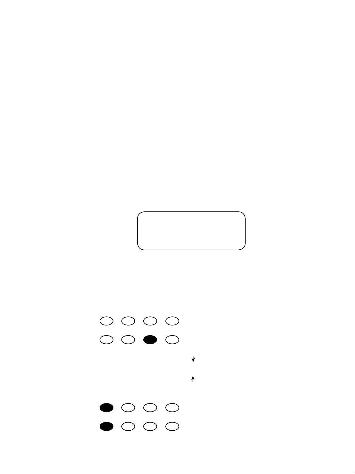
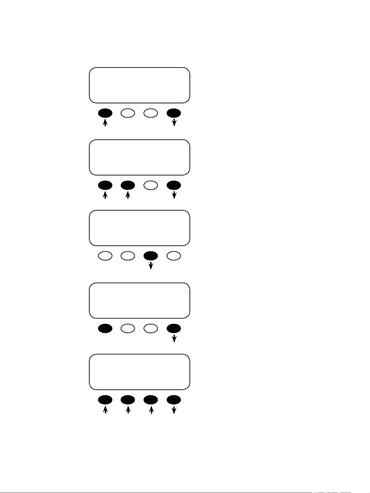
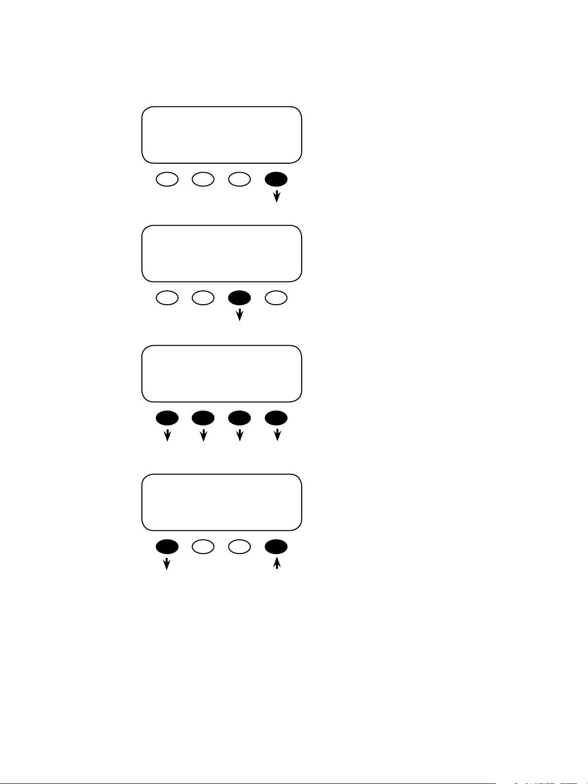
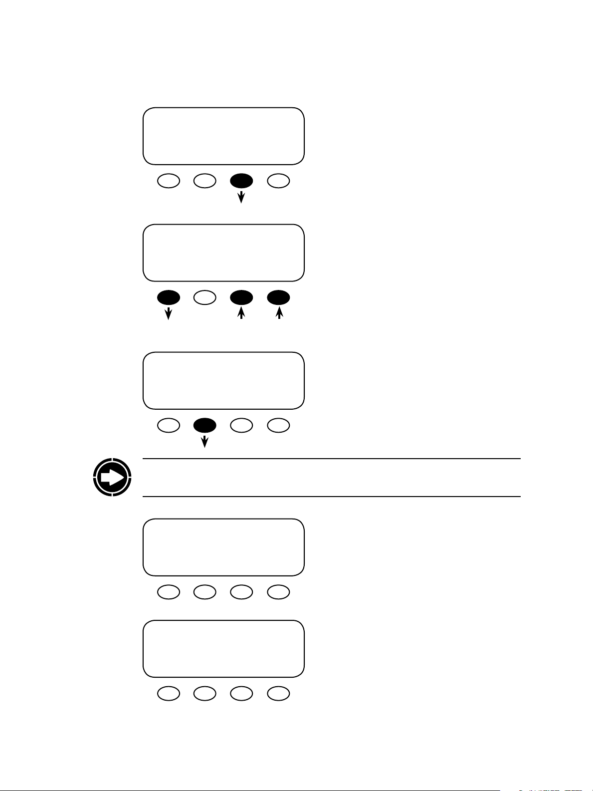
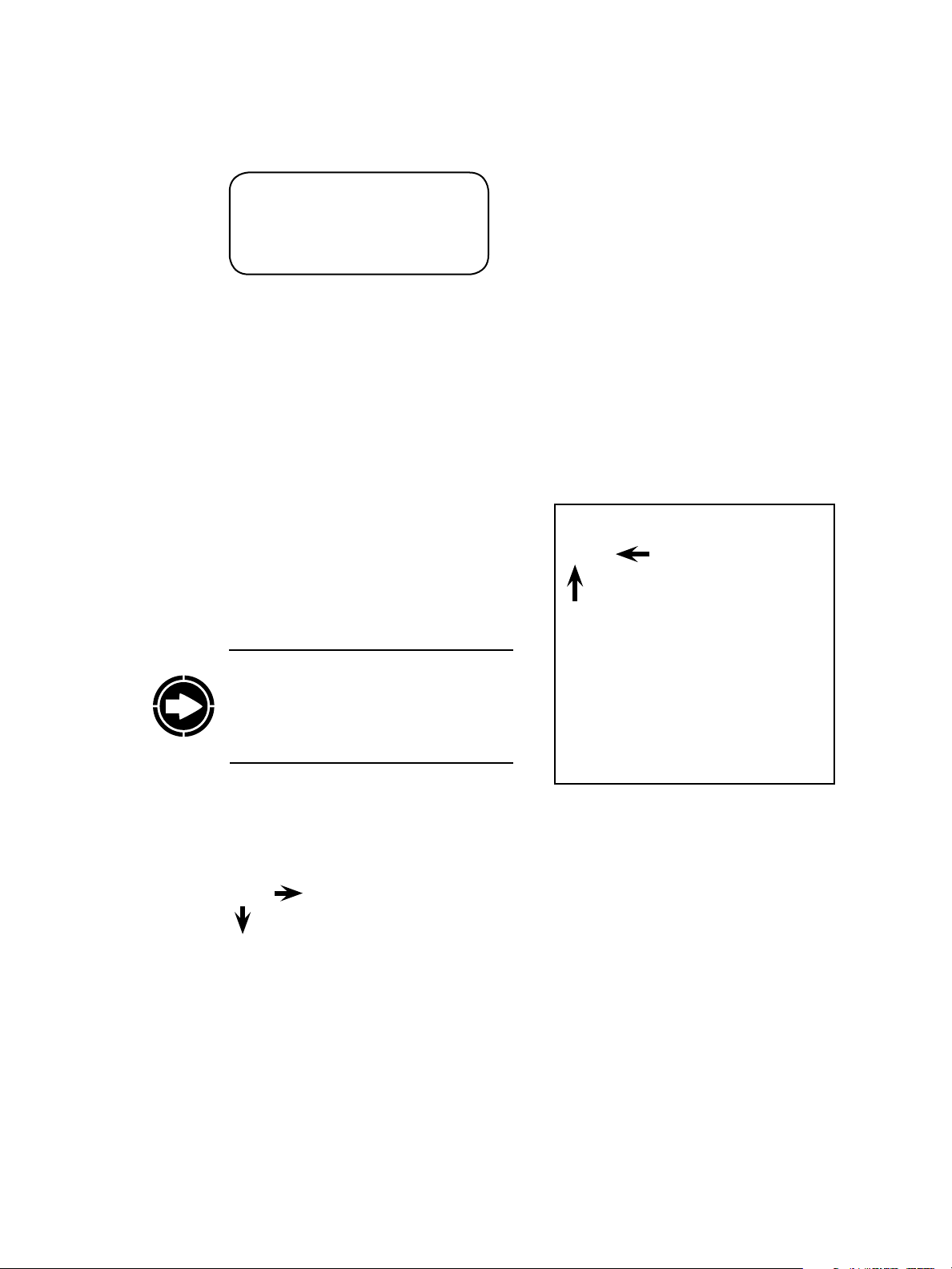
Key to the Example Diagrams
DOWN
HBX GRIDUSE AGS PG2
So keys
Solid black indicates key can be pressed
Down arrow will lead to the next screen
Up arrow points to one or more keys that will
change a value
Pressing <DOWN> leads to the next menu
18
UP
Pressing <UP> leads to the previous menu
Page 19
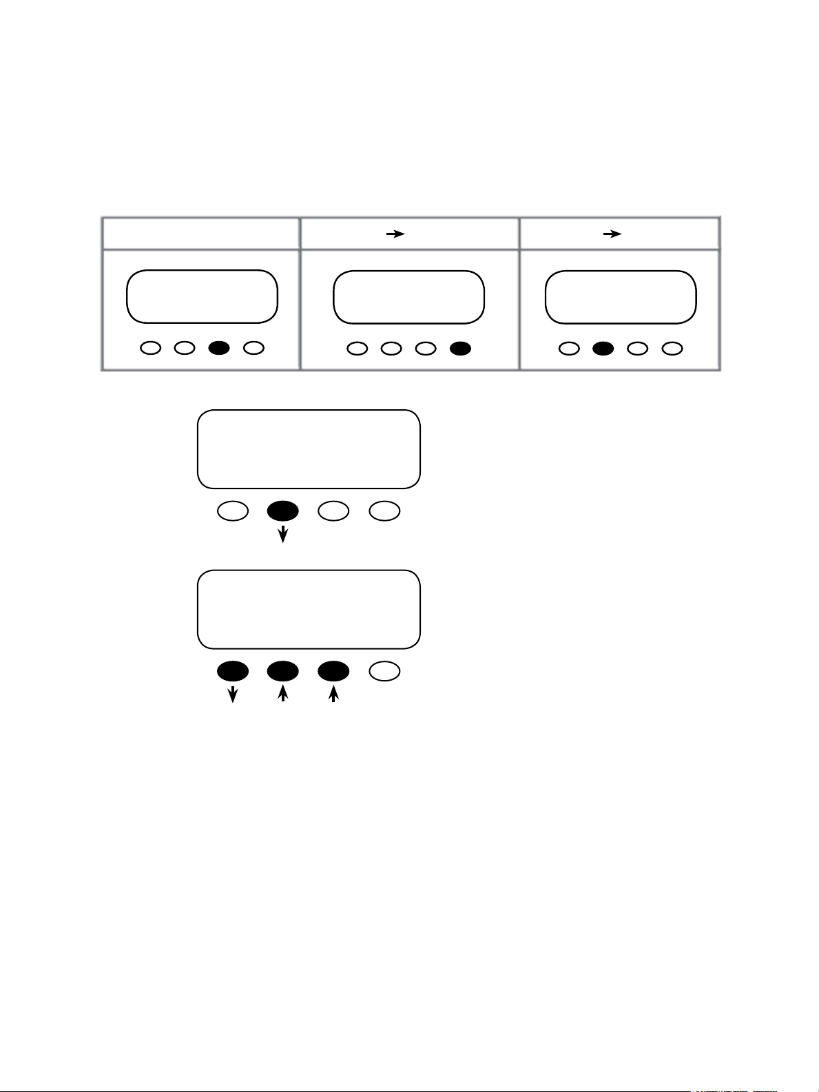
Although the OutBack MATE menu display screens vary depending on the unit’s soware
version, the menu structures and navigation are the same for all versions. e MATE uses a
branching menu structure to display various OutBack products’ operation modes and statuses.
e menus are divided by product type and are categorized by either type of settings or the
information being displayed as shown in the following example.
MAIN---------------------------------
12:17:04P
SUM STATUS SETUP ADV
STATUS SCREEN-----------------choose device:
FX CC DC MAIN
STATUS/FX/PAGE 1---------------choose category:
MODES METER BATT PG2
P00
inv kw zer kw
chg kw buys kw
DOWN STATUS PORT
STATUS/FX/METER–----------P00
output vac
voltage
DOWN UP TOP PORT
All the screens showing the FX’s AC meters are
grouped together in one menu branch allowing
the user to nd the required meter with a minimum of key presses.
19
Page 20

2 MATE Setup
20
Page 21
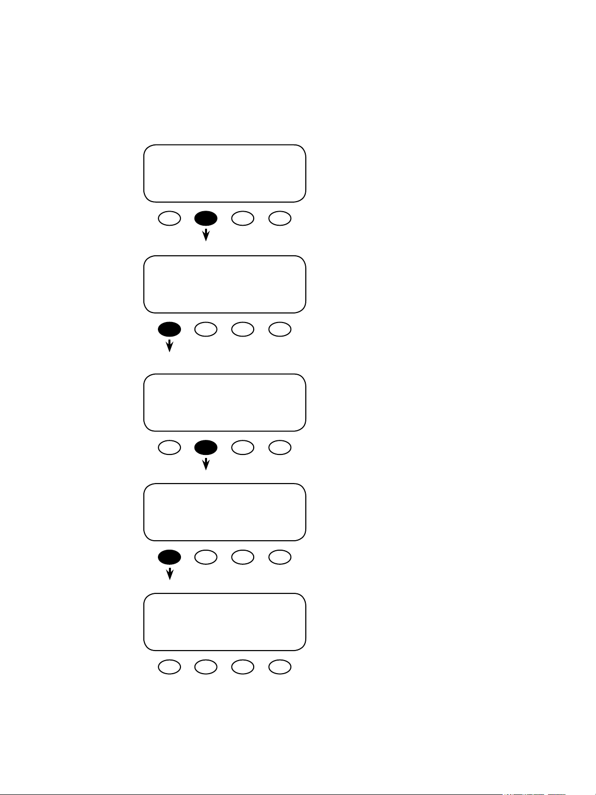
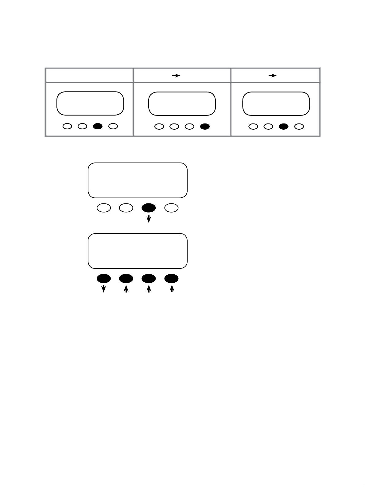
Setup the MATE
MAIN---------------------------------
9:57:32A
SUM STATUS SETUP ADV
SETUP------------------------------choose device:
FX MATE
SETUP/MATE/PAGE 1-------------mate code rev: 402
choose category:
CLOCK CNT GLOW PG2
Start with the <MAIN> screen, which appears
aer the power-up screens, and press the
<SETUP> so key.
Press the <MATE> so key.
is screen displays the MATE’s code version and
some SETUP choices. Press the <PG2> so key
for a second screen of SETUP choices.
21
SETUP/MATE/PAGE2-------------choose category:
PG1 SUMRY COMM PG3
SETUP/MATE/PAGE3-------------choose category:
PG2 BEEP MAIN
Note: To return the MATE to its factory default settings, please see page 96
Press the <PG1> so key to return to the previous
screen, SETUP/MATE/PAGE1.
Page 22
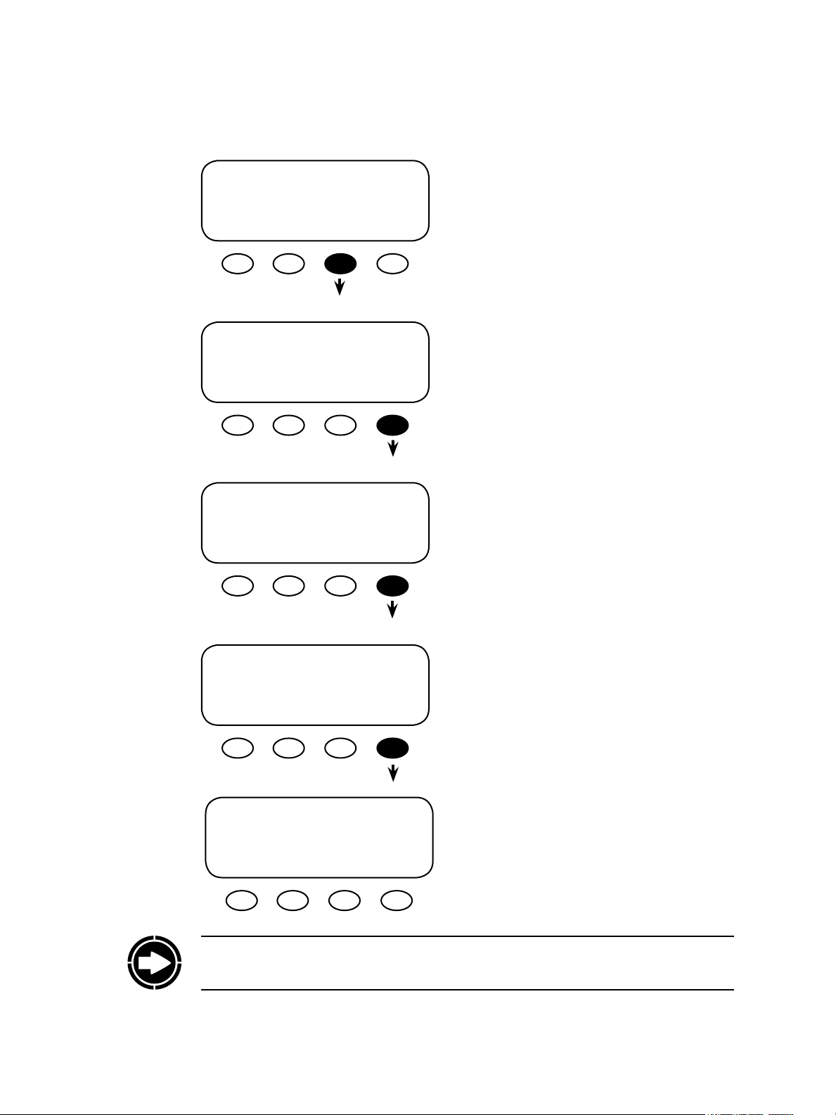
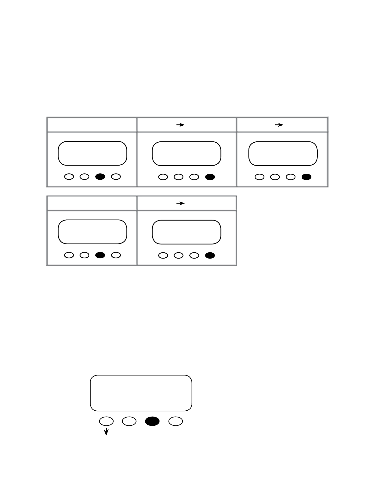
Setting the Clock
Why you want to do it: Certain functions—such as when to use grid-supplied power (Grid-Use
Mode) or generator (Advanced Generator Start Mode)—are dependent on accurate time and
date settings. Otherwise, the system will never work optimally.
SETUP/MATE/PAGE1-------------mate code rev: 402
choose category:
CLOCK CNT GLOW PG2
Choose <CLOCK> from the SETUP/MATE/
PAGE1 SETUP choices screen.
SETUP/MATE/CLOCK--------------
Tu 1/01/03
12:00:00P
BACK DATE TIME
<DATE> and <TIME> adjust the MATE’s clock
and calendar functions. e correct time and date
are required for some MATE Control Modes to
operate correctly. Pushing the <BACK> so key
returns you to the previous screen.
NOTE: e MATE clock does not automatically adjust for daylight savings time or leap year.
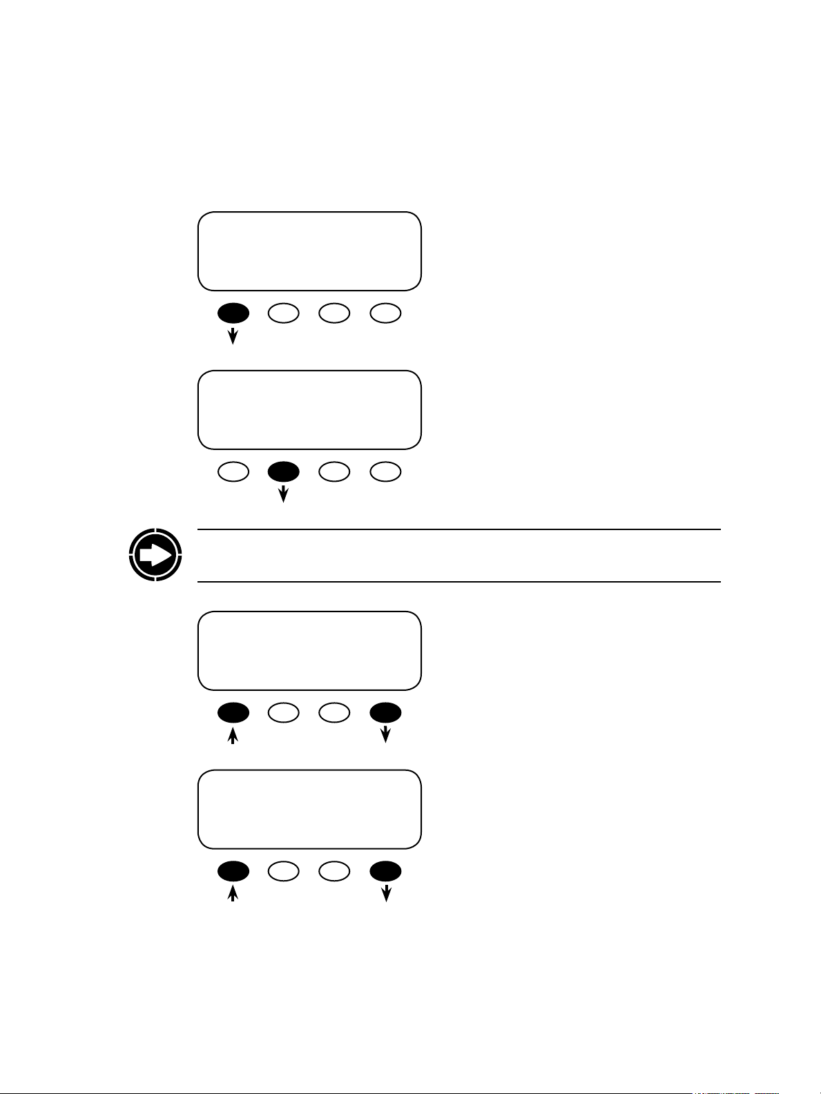
To adjust the date, press the <DATE> so key to
Current Day
bring up the Current Day menu.
Tu 9/26/07
INC SET
DAY MONTH
<INC DAY> changes the day (Monday-Sunday).
Press the <SET MONTH> so key aer
changing the day. e next screen, which shows
automatically aer hitting <SET MONTH>,
ADJUST DAY AND THEN
MONTH
adjusts the month.
22
Current Month
Mo 9/26/07
INC SET
MONTH DATE
ADJUST MONTH AND
THEN DATE
<INC MONTH> changes the month.
Press the <SET DATE> so key aer changing
the month. e next screen adjusts the date.
Page 23
Current Day
Mo 9/26/07
INC SET
DATE YEAR
ADJUST DATE AND THEN YEAR
<INC DATE> changes the day of the month. Press
the <SET YEAR> so key aer changing the date.
e next screen adjusts the year
Current Year
Mo 9/26/07
INC DEC
YEAR YEAR DONE
EITHER
SETUP/MATE/CLOCK------------- Mo 1/01/07
12:00:00P
BACK DATE TIME
Current Hour
12:00:00P
INC SET
HOUR MIN
<INC YEAR> or <DEC YEAR> changes the year
setting. Press the <DONE> so key aer the date
change is nal. is returns the MATE to the
SETUP/MATE/CLOCK screen.
<TIME> sets the MATE’s time. Pressing the
<TIME> so key leads to the Current Hour
screen.
<INC HOUR> sets the correct hour. Press the
<SET MIN> so key when nished to return to
the Current Minute screen.
23
Current Minute
12:00:00P
INC DEC RESET
MIN MIN SEC DONE
Adjust the minutes by pressing the <INC MIN>
or <DEC MIN> so keys as needed. Pressing the
<RESET SEC> so key begins the seconds count
at zero. Pressing the <DONE> so key returns the
MATE to the SETUP/MATE/CLOCK screen.
Page 24
Contrast Adjustment
Why you want to do it: Everyone has dierent eyesight and ambient lighting varies with every
location of a MATE. Like any other monitor, you may want to adjust the lighting and contrast
for easier reading.
PATH
MAIN------------------------------------
9:57:32A
SUM STATUS SETUP ADV
SETUP/MATE/PAGE1-------------mate code rev: 402
choose category:
CLOCK CNT GLOW PG2
SETUP/MATE/CNT-----------------contrast: 30%
BACK INC DEC
SETUP------------------------------choose device:
FX MATE
Press the <CNT> (CONTRAST) so key from the
<SETUP/MATE/PAGE > Setup choices screen.
<CNT> sets the desired contrast level.
<INC> increases the contrast level and <DEC>
decreases the contrast level. Aer adjusting the
contrast, press the <BACK> so key to return to
the previous SETUP/MATE/PAGE 1 screen.
SETUP/MATE/PAGE1---------------mate code rev: 402
choose category:
CLOCK CNT GLOW PG2
24
Page 25
Backlight Adjustment
PATH
MAIN------------------------------------
9:57:32A
SUM STATUS SETUP ADV
Choose <GLOW> from the SETUP/MATE/PAGE 1 Setup choices screen:
SETUP/MATE/PAGE1-------------mate code rev: 402
Choose Category
CLOCK CNT GLOW PG2
SETUP/MATE/GLOW-------------backlight controls
BACK LEVEL MODE TIME
SETUP------------------------------choose device:
FX MATE
On the SETUP/MATE/GLOW screen, pressing
the <GLOW> so key brings up three backlight
settings:
t LEVEL
t MODE
t TIME
<LEVEL> controls the backlight brightness and
is adjustable from 0% to 100% using <INC> and
<DEC> so keys.
<MODE> allows user to set the backlight to al-
ways o, auto-o aer a time, or always on by selecting <OFF>, <AUTO>, or <ON>, respectively.
SETUP/MATE/PAGE1-------------mate code rev: 402
choose category:
CLOCK CNT GLOW PG2
25
<TIME> sets the auto-o time limit from 1 to 60
minutes using <INC> and <DEC> so keys. is
is how long the MATE waits aer the last button
press to turn o the backlight. Once the backlight
has turned o, any button press on the MATE will
turn it back on.
<BACK> returns to the previous screen(s) and
back to the SETUP/MATE/PAGE 1 screen.
Page 26

3 MATE Communications Options
26
Page 27
Communications Options
Why you want them: e MATE communicates commands to dierent components. It needs
to be aware of any newly added or moved devices so it can recognize them. An error reading
doesn’t mean the system is failing, but that the MATE is looking for a component that has been
moved from one HUB Port to another or has been disconnected completely. e MATE is
trying to account for the system components.
PATH
MA IN- --- --- -- --- --- --- --- --- ---- 9:57: 32 A
SUM STATUS SETUP ADV
PATH
SE TUP /MATE/ PAGE2- --- --- --- -ch oos e c ate go ry:
PG1 SUMRY COMM MAIN
Press the <COMM> so key from the <PAGE 2> Setup choices screen for MATE
communications options:
t <REPOLL> forces the MATE to “rediscover” all the OutBack devices it is connected to.
SE TUP --- --- -- --- --- --- --- --- --Ch oos e p rod uct:
FX MATE
SETUP/MATE/PAGE2---------------choose category:
BACK REPOLL PC DEBUG
SE TUP /MATE/ PAGE1- --- --- --- ma te cod e r ev: 402
ch oos e c ate go ry:
CLOCK CNT GLOW PG2
is must be used any time an OutBack device is moved or added to a HUB.
27
t <PC> will allow you to enable or disable the MATE’s RS232 communications port. is
setting must be enabled if you use any third party logging or control soware.
t <DEBUG> tracks communication errors involving the OutBack HUB.
SETUP/MATE/PAGE2-------------choose category:
From the SETUP/MATE/PAGE2 screen, press the
<COMM> so key.
PG1 SUMRY COMM MAIN
Page 28
SETUP/MATE/PAGE2-------------choose category:
BACK REPOLL PC DEBUG
To debug the system, press the <DEBUG> so
key.
SETUP/MATE/COMM-------------comm errors:
BACK VIEW RSET
00:000 01:000 02:000
03:000 04:025 05:001
06:001 07:001 08:001
09:001 10:001 2M:001
SETUP/MATE/COMM-------------comm errors:
BACK VIEW RSET
On the DEBUG screen, rst press the <VIEW>
so key to bring up a list of HUB ports with a
count of communications errors for each port;
<RESET> allows you to reset the error counting
display (see next screen).
is is a typical VIEW screen showing the HUB
Ports and any communication errors in the
system. e numbered port with more than one
error will need correcting. Aer the errors are
corrected, all the used ports will return to 000
or 001 values aer pushing the <RSET> so key.
Press any so key to return to the SETUP/MATE/
COMM screen. To correct errors, please see “Errors and Debugging” in the section that follows. If
no errors are present, pressing any so key returns
to the previous SETUP/MATE/COMM screen.
Press the <RSET> so key to clear the errorcounting display. Press the <BACK> so key
to return to the “choose category” screen. Press
<VIEW> to return to the previous screen.
28
Page 29
SETUP/MATE/PAGE2-------------choose category:
BACK REPOLL PC DEBUG
Press the <PC> so key to enable or disable the
MATE’s RS232 communications port.
SETUP/MATE/PAGE2-------------PC communications: OFF
BACK OFF ON
In the PC communications screen, choose ON or
OFF by pressing the respective so key. Press the
<BACK> so key to return to the choose category
screen.
SETUP/MATE/PAGE2-------------choose category:
Press the <REPOLL> so key aer a device is
added to, moved, or removed from the HUB.
BACK REPOLL PC DEBUG
NOTE: Disconnecting the MATE’s CAT5 cable and then reconnecting it also performs the
re-poll task, but the cable can be inconvenient to remove from a mounted MATE.
29
Searching for Devices
HUB Found
Port Assignment
1> FX 2> FX 3> CC 4> CC
5> 6> 7> 8>
9> 10> 2M>
e MATE has found the HUB and will automatically go to the Port Assignment screen.
Aer displaying the devices connected to each
Port, the MATE returns to the choose category
screen on its own.
Page 30
Communication Errors
--A COMM ERROR HAS
OCCURED
VIEW
DEBUG
Errors and Debugging
Communication errors (COMM ERR) that occur with OutBack Power Systems components
are oen the result of loose, damaged, or unplugged cables. ey can also occur if AGS (Advanced Generator Start) Mode is used and the wrong port is designated for the generator or if
the system is damaged by a lightning strike. When a communication error occurs, the COMM
ERR message will appear on any MATE screen in view.
A sample DEBUG screen looks like this:
00:000 01:000 02:000
03:000 04:025 05:001
06:001 07:001 08:001
09:001 10:001 2M:001
NOTE:
t Port 00 is a MATE connected directly to
an FX, no HUB is used.
t Port 2M is the “2nd MATE” Port and is
inoperable.
MORE
INFO
e A COMM (communication) ERROR
HAS OCCURRED screen appears when a
communication error among the components
occurs.
Explanation of Ports
01:000 Port Status
Port Number
• Port 00 is the MATE Port
• Port 2M is inoperable.
• 01—10: FX or CC Ports
• 000: a device is present.
• 001: no device present.
• Any other status number means a
device was previously present and lost
contact, resulting in errors.
30
Here’s how to read the DEBUG screen:
01:000 Number of errors (zero in this case) present at this port.
Port 01
An unused port will show one error:
09:001 Port 09 has no component; the single error is the system default.
A port with a large number of errors requires action. In this example, Port 4 needs attention.
04:025 Port 04 shows 25 errors.
Page 31

Advancing errors (the count is increasing on the DEBUG screen) mean the HUB is not nding
a device that was previously there. In order, try the following:
1. Check that the device’s DC breaker is on and operating correctly, that the device itself is on,
and that the CAT5 cable connecting the device to the HUB is plugged in at both ends. en
re-poll the system (SETUP MATE PG2 COMM REPOLL, see page 29)
2. Check the DEBUG screen to conrm the problem is solved.
3. Swap HUB ports with another device, each using its own CAT5 cable. Re-poll the system
and check for errors on each port. If the error moved, the problem is with the device or
the cable between the Port and the device. If the error remains on the same Port, then the
problem is with the HUB.
4. Try connecting the MATE directly to the device. If the MATE recognizes the device, the
problem could lie with the cable connecting the device to the HUB or with the HUB port
itself. An unrecognized device could itself be damaged.
31
Page 32

4 MATE Summary Screens
32
Page 33

Summary Screens
e Summary screens provided by the MATE:
• Summarize the current status of any FX, OutBack Charge Controller and/or FLEXnet DC
connected to it.
• Can be accessed from the <MAIN> screen by pressing the <SUM> so key and can be set
to pop up like a screen saver aer a delay (See Summary Screen Options on the next page
for more setup information).
Any MATE so key pressed while the Summary screen is being displayed returns you to the
screen that was active before the Summary screen was displayed. Pressing the two lower le
so keys at the same time opens the MAIN Menu screen.
MAIN--------------------------------
12:00:30P
SUM STATUS SETUP ADV
If the MATE has a FLEXnet DC connected to it,
an initial FLEXnet DC screen will be displayed
as the Summary default screen.
E F
Battery Discharging
State of Charge 100%
DC Now 25.4V 100%
In 0.1A 0.000 kW
Out 0.4A 0.010kW
Bat -0.3A 0.010kW
DC TODAY minSOC 97%
In 102AH 2.70 kWH
Out 93AH 2.44kWH
Bat 9AH 0.26kWH
Pressing the second so key brings up the next
three FLEXnet DC summary screens as well as the
FX and Charge Controller summary screens.
e FLEXnet DC summary screens display
the battery state of charge, including the day’s
minimum, the current DC voltage, and the in
and out kilowatt hours and amp hours.
33
DC BAT 25.4V 100%
Bat -0.3A -0.010kW
Net 0AH 0.00kWH
Days Since Full
1.1
Page 34

FX Summary Screen
FX Total 12.6V 97%
Inverting 0.000kW
AC Loads 0.000kW
Buying $ 0.000kW
OutBack Charge Controller Summary Screen
If the MATE has one or more FXs connected to
it and does not have a FLEXnet DC as part of the
system, an FX Summary screen will be displayed
as the Summary default screen. Otherwise, it will
follow the FLEXnet DC summary screens.
e FX summary screen’s values summarize
power ow in an FX system as well as the nontemperature compensated battery voltage.
CC TOTALS 13.3V
Output 0A 0.000kW
Today 0.0kWh
0 AH
e CC summary applies to all OutBack Charge
Controller. Its screen shows the voltage level of
the battery (also non-temperature-compensated)
and the amount of power (1.5kw) being supplied
to the battery. is screen is the default Summary
screen if the Charge Controller is directly
connected to the HUB. e AH value applies only
to the FLEXmax 80 Charge Controller
Summary Screen Options
Why you might want them: Summary screens show the current status of one or more FXs or
Charge Controllers. Given that each user and system is dierent, the MATE oers the choice of
viewing the status of either component as well as the timing of those displays.
PATH
PATH
MAIN------------------------------------
9:57:32A
SUM STATUS SETUP ADV
SETUP/MATE/PAGE2-------------choose category:
PG1 SUMRY COM MAIN
SETUP------------------------------choose device:
FX MATE
SETUP/MATE/PAGE1-----------------mate code rev: 402
choose category:
CLOCK CNT GLOW PG2
SETUP/MATE/PAGE2----------------choose category:
PG1 SUMRY COMM PG3
Press the <SUMRY> so key from the <SETUP
MATE/PAGE2> Setup choices screen.
34
SETUP/MATE/SUMMARY---------summary control
BACK TYPE DELAY ROLL
Pressing the <SUMRY> so key brings up the
SETUP/MATE/SUMMARY (summary control)
screen options <TYPE> and <TIME>.
Page 35

SETUP/MATE/SUMMARY--------summary control
BACK TYPE DELAY ROLL
To choose the SUMMARY screen you want to
view automatically and also view via the MAIN
menu, press the <TYPE> so key on the SETUP/
MATE/SUMMARY screen.
SETUP/MATE/SUMMARY/TYPE--summary Roll
screen type
BACK INC DEC
Press either <INC> or <DEC> up to six
times to change Summary screen
SETUP/MATE/SUM/TYPE--------summary None
screen type
BACK INC DEC
SETUP/MATE/SUM/TYPE--------summary FXOnly
screen type
BACK INC DEC
Press either the <INC> and <DEC> so keys to
change the summary screen
Roll—switches between FX and CC (Charge Controller) summary screens automatically if both
are connected to the MATE through an OutBack
Power Systems HUB.
None—disables the SUMMARY screen from
automatically opening; the SUMMARY screen can
still be accessed via the <SUM> so key on the
MAIN screen.
FX Only—displays the FX SUMMARY screen.
35
Page 36

SETUP/MATE/SUM/TYPE---------summary CC Only
screen type
BACK INC DEC
CC Only—displays the CC SUMMARY screen.
Pressing the <INC> opens the DC Only summary
screen.
SETUP/MATE/SUM/TYPE---------summary DC Only
screen type
BACK INC DEC
SETUP/MATE/SUM/TYPE--------summary DC OnlySimple
screen type
BACK INC DEC
SETUP/MATE/SUMMARY---------summary control
BACK TYPE DELAY ROLL
DC Only—displays the DC SUMMARY screen.
Pressing the <INC> so key opent the DC Only
Simple screen.
From the DC OnlySimple screen, press the
<BACK> so key to return to the summary con-
trol screen.
36
NOTE: An Charge Controller or FX must be connected to the MATE or HUB to have “CC
Only” or “FX Only” modes.
Having chosen a Summary type—None, Roll, FX Only, CC Only, DC Only or DCSimple:
1. Aer exiting that screen, the SUMMARY type will automatically appear whenever the
MATE has been inactive for the <TIME> set point (very much like a screensaver on a
computer monitor).
2. e chosen SUMMARY type will also be the SUMMARY manually called up by pushing
the <SUM> so key on the MAIN menu.
3. If the MATE is connected to a HUB with both Charge Controller and FX components, it
will switch between the CC and FX SUMMARY screens every 20 seconds when in “Roll”
mode.
4. If you choose “None,” the MATE continues to display the last active screen viewed; if you
press the <SUM> so key on the MAIN menu when “None” is chosen, the FX SUMMARY
screen appears.
Page 37

PATH
PATH
MAIN--------------------------------
9:57:32A
SUM STATUS SETUP ADV
Pressing the <SUM> so key in the MAIN menu
brings up your chosen SUMMARY screen or, if
None is chosen, it will bring up the FX SUMMARY screen as a default. To adjust the timing of the
SUMMARY screen display, see the next section.
MAIN-----------------------------------
9:57:32A
SUM STATUS SETUP ADV
SETUP/MATE/SUMMARY---------summary control
BACK TYPE DELAY ROLL
SETUP/MATE/SUMMARY/TYPE-sum screen 19 minutes
delay time
BACK INC DEC
SETUP-------------------------------
choose device:
FX MATE
SETUP/MATE/PAGE1----------------mate code rev: 402
choose category:
CLOCK CNT GLOW PG2
SETUP/MATE/PAGE2----------------choose category:
PG1 SUMRY COMM MAIN
In the SETUP/MATE/SUMMARY screen, press
the <DELAY> so key; this will take you to
the sum screen delay time screen. Pressing the
<ROLL> so key leads to the sum screen roll rate
screen.
SETUP/MATE/SUMMARY/TYPE-sum screen 10 seconds
roll rate
BACK INC DEC
37
<DELAY> in SUMMARY mode shows
how long it takes for a SUMMARY
screen to be automatically displayed.
is time can be increased or decreased
by pressing the <INC> and <DEC> so
keys. Aer the SUMMARY screen delay
time is chosen, press the <BACK> so
key to return you to the SETUP/MATESUMMARY screen.
e roll rate is how oen the MATEswitches between the FX and CC summary screens. e rate
can be adjusted with the <INC> and <DEC> so
keys. Pressing the <BACK> so key returns to the
SETUP/MATESUMMARY screen.
Page 38

5 MATE Status Screens
38
Page 39

STATUS Screens
Why you want them: Status screens give the user a breakdown of individual activities of the FX
Series Inverter/Charger(s) and the Charge Controller(s), including AC and DC voltage and AC
current meters. It is these individual readings that combine to produce the Summary screens
noted earlier and allow monitoring of the system operation.
MAIN---------------------------------
9:57:32A
SUM STATUS SETUP ADV
STATUS ----------------------------choose device:
FX CC DC MATE
NOTE: Not all STATUS screens are applicable to all FX models. e screens dier by product
type and revision. See the Menu Map at the end of the manual for locations of all of the status
screens available. Consult your specic OutBack product owner manual for an explanation of
all the operating modes and meters.
Press <STATUS> on the Main menu to access the
STATUS menu. STATUS contains all the meters
and mode displays for OutBack products connected to the MATE.
e STATUS menu is divided rst by product and
then into menu categories, such as meter, modes,
and statuses.
39
STATUS/CC/PAGE 1--------------
MODE METER SETP PG2
Typical CC Status Screen Typical FX Status Screen
NOTE: Other than oering manual on/o control of its AUX relay, the MATE has no control
over the workings of the CC Charge Controller except when the system is undergoing a global
EQ charger mode. At this time, the system uses both the FX and the Charge Controller(s) to
charge the batteries.
STATUS/FX/PAGE 1---------------choose category
MODE METER BATT PG2
Page 40

Reading a STATUS Screen
STATUS/FX/PAGE1--------------choose catagory
MODES METER BATT PG2
• MODE: a functioning condition or state of operation
• METER: displays inverter and charger activity, including output and input AC voltage, and
AC inverter, charger, and input current
• BATT: displays the battery temperature, voltage and the various set points for the dierent
recharging cycles as well as the time remaining to complete any of those cycles
• PG2: pressing the <PG2> so key opens the next selection of STATUS screens
• ERROR: various FX errors and their causes; an error can shut the FX down
• WARN(ING): FX warning situations; warnings will not shut the FX down
• PG3: Pressing the <PG3> so key opens the last STATUS screen
• DISCON: lists the reasons the FX disconnects from an AC source
• SELL: displays a number representing the reason the FX stops selling power to the grid; this
number is used by technicians for troubleshooting grid-tied FX units
STATUS/FX/PAGE2--------------choose catagory
PG1 ERROR WARN PG3
STATUS/FX/PAGE3--------------choose catagory
PG2 DISCON SELL MAIN
e second line
indicates the FX
or Charge Controller MODE
STATUS/FX/MODE----------- P00
inv control: ON
CHANGE
DOWN STAT MODE PORT
Pressing the <CHANGE MODE> so key
changes the operation of the mode shown
on the screen; it does not change to another
mode altogether. To change modes, press the
<DOWN> so key.
e status of
“inv(erter)
control” is “ON.”
To choose an FX
on a specic Port,
press the <PORT>
so key.
40
Page 41

FX STATUS MODE Screens
STATUS/FX/PAGE1-----------------choose category:
MODES METER BATT PG2
STATUS/FX/MODE------------P00
chr control: ON
CHANGE
DOWN UP MODE PORT
STATUS/FX/MODE------------P00
inv control: ON
CHANGE
DOWN STAT MODE PORT
Push <STAT> to return to the
choose category STATUS page.
STATUS/FX/PAGE1-------choose category:
MODES METER BATT PG2
Pressing the <METER> so key
brings up the rst METER screen.
STATUS/FX/MODE------------P00
inv control: ON
CHANGE
DOWN STAT MODE PORT
STATUS/FX/MODE-------------P00
aux control: AUTO
CHANGE
DOWN UP MODE PORT
MODE Screens
• Pressing the <CHANGE MODE> so key on any
MODE screen allows the user to change the operation
of that individual mode, i.e., activate the function, shut
it o, etc. Aer changing the operation (or leaving it
alone), the user presses the <OK> so key to return to
the MODE screen whose operation was changed. Press
the <DOWN> so key to view the next mode.
• inv control: shows the status of the inverter function*
• AC in control: the FX accepts or drops an AC source*
• chr control: shows charger activity*
• aux control: controls 12 VDC and 0.7 ADC loads
which can be used to run a fan, activate an alarm, signal a generator start and other low-power functions*
• eq enabled: shows status of the equalize recharging
cycle and allows user to start or stop the cycle*
* ese modes can be controlled and adjusted in greater
detail in the INVERTER, CHARGER, and AUXILIARY
menus and through the AC IN hot key respectively.
STATUS/FX/MODE-----------P00
ac in control: USE
CHANGE
DOWN UP MODE PORT
STATUS/FX/MODE-------------P00
eq enabled: No
CHANGE
UP MODE PORT
Push <UP> until the inv
control screen appears.
41
Page 42

FX STATUS METER Screens
Charge P00
inv 0.0kw zer 0.0kw
chg 0.0kw buy 0.0 kw
DOWN STATUS PORT
STATUS/FX/METER------------P00
inverter 0.0 aac
current
DOWN UP TOP PORT
STATUS/FX/METER----------P00
sell 0.0 aac
current
DOWN UP TOP PORT
STATUS/FX/METER----------P00
sell 0.0 aac
current
DOWN UP TOP PORT
STATUS/FX/METER---------P00
output 117 vac
voltage
DOWN UP TOP PORT
STATUS/FX/METER----------P00
charger 0.0 aac
current
DOWN UP TOP PORT
STATUS/FX/METER---------P00
FX rmware 61
revision
DOWN UP TOP PORT
STATUS/FX/METER---------P00
input 118 vac
voltage
DOWN UP TOP PORT
STATUS/FX/METER--------P00
input 0.0 aac
current
DOWN UP TOP PORT
STATUS/FX/METER--------------end of meter menu
UP TOP STATUS
Push <UP> to
return to the rst
METER screen.
Push <STAT>
to return to the
“choose category”
STATUS screen.
42
Pressing the <BATT> so key brings
up the rst FX BATT screen.
e rst Meter screen shows what the
inverter is doing at the time this screen
is viewed. A grid-tied FX will also
show any target activity. e lists below
show the possible activities and target
activities. An o-grid FX will only show
the current activity.
Activity
O
Search
On
Charge
Silent
Float
EQ
Chr O
Support
Sell
Passthru
Target Activity
Sell
RE
Float
Bulk EQ
METER Screens
e METER screens display current and voltage
measure-ments and the version of FX soware.
• charge: the current FX mode
• output voltage: available AC at the FX AC output
• input voltage: available AC at the FX AC input,
normally from a utility or a generator
• inverter current: available current at FX AC output
terminals when the inverter is ON and no AC
source is connected
• charger current: shows the amount of AC current
used by the FX charger
• input current: AC current owing into the FX AC
input
• sell current: AC current being sold to the grid
• FX rmware: current FX soware version
e METER MODE values cannot be changed in the
STATUS screens.
Page 43

FX STATUS Batt(ery) Screens
STATUS/FX/MODE-------------P00
battery 13.6 vdc
actual
DOWN STATUS PORT
STATUS/FX/BATT---------------P00
absorb 00.0 hrs
time remaining
DOWN UP TOP PORT
STATUS/FX/BATT---------------P00
reoat 12.5 vdc
set point
DOWN UP TOP PORT
STATUS/FX/BATT---------------P00
batt temp. 255
(not in degree C/F)
DOWN UP TOP PORT
STATUS/FX/MODE-------------P00
battery 13.6 vdc
temp compensated
DOWN UP TOP PORT
STATUS/FX/BATT---------------P00
oat 13.6 vdc
set point
DOWN UP TOP PORT
STATUS/FX/BATT---------------P00
equalize 14.4 vdc
set point
DOWN UP TOP PORT
STATUS/FX/BATT--------------------end of battery menu
UP TOP STATUS
STATUS/FX/METER-------------P00
battery 14.4 vdc
set point
DOWN UP TOP PORT
STATUS/FX/BATT---------------P00
oat 24.0 hrs
time remaining
DOWN UP TOP PORT
STATUS/FX/BATT---------------P00
equalize 00.0 hrs
time remaining
DOWN UP TOP PORT
STATUS/FX/PAGE1------------------choose catagory:
MODES METER BATT PG2
43
Pressing the <PG2> so key
brings up more STATUS
categories.
BATT(ERY) Screens
• battery actual: battery voltage as measured by the FX
• battery temp compensated: the Remote Temperature Sensor (RTS) must be connected to this value to be
measured
• absorb set point: charger set point for absorb recharging cycle
• absorb time remaining: time remaining in absorb recharging cycle
• oat set point: battery set point for oat recharging cycle
• reoat set point: at this battery voltage, the charger restarts the oat recharging cycle
• equalize set point: charger set point for equalize recharging cycle
• equalize time remaining: time remaining in equalize recharging cycle
• batt temp: this value, which reects the battery temperature, is used by the charger when an RTS is connected
to the FX
e BATT MODE values cannot be changed in the STATUS screens.
Page 44

FX STATUS ERROR Screens
STATUS/FX/PAGE1------------------choose category:
MODES METER BATT PG2
STATUS/FX/ERROR----------P00
stacking No
error detected
DOWN UP TOP PORT
STATUS/FX/ERROR----------P00
phase loss No
error
DOWN UP TOP PORT
STATUS/FX/ERROR---P00 ac output
No
backfeed
DOWN UP TOP PORT
STATUS/FX/PAGE2------------------choose category:
PG1 ERROR WARN PG3
STATUS/FX/ERROR----------P00
inverter No
overtemp
DOWN UP TOP PORT
STATUS/FX/ERROR----------P00
high battery No
voltage
DOWN UP TOP PORT
STATUS/FX/ERROR----------------- end of error menu
UP TOP STATUS
STATUS/FX/ERROR-----------P00
Low ac output No
voltage
DOWN STATUS PORT
STATUS/FX/ERROR----------P00
low battery No
voltage
DOWN UP TOP PORT
STATUS/FX/ERROR----------P00
ac output No
shorted
DOWN UP TOP PORT
STATUS/FX/PAGE2----------------choose category:
PG1 ERROR WARN PG3
44
Push <STAT> to return to the “choose
category” STATUS /FX/PAGE2
Push <WARN> to see
the WARN(ING) Menu.
ERROR Screens
• low ac output voltage: inverter could not supply enough AC voltage to meet demand
• stacking error detected: communication problem among stacked FXs
• inverter overtemp: FX has reached its maximum allowed operating temperature
• low battery voltage: battery voltage is below the LOW BATTERY CUT-OUT VOLTAGE set point (this is a
common error and will light up even with low AC out or AC shorted)
• phase loss error: not operational
• high battery voltage: battery voltage rose above the safe high battery voltage level for 10 seconds
• ac output shorted: inverter reached its maximum current and shutdown
• ac output backfeed: usually indicates another AC power source was connected to the FX’s AC output
ERROR screens can only display errors; they do not oer any means to correct them. ese are hard faults.
e LED is solid and the inverter must be turned o and then on to reset.
Page 45

FX STATUS WARN(ING) Screens
STATUS/FX/PAGE2----------------choose category:
PG1 ERROR WARN PG3
STATUS/FX/WARN--------------P00
acin voltage No
too high
DOWN UP TOP PORT
STATUS/FX/WARN-------------P00
temperature No
sensor fault
DOWN UP TOP PORT
STATUS/FX/WARN------------P00
airtemp 190
STATUS/FX/WARN-------------P00
acin freq No
too high
DOWN STATUS PORT
STATUS/FX/WARN-------------P00
acin voltage No
too low
DOWN UP TOP PORT
STATUS/FX/WARN-------------P00
internal comm No
error detected
DOWN UP TOP PORT
STATUS/FX/WARN-----------P00
fettemp 184
STATUS/FX/WARN-------------P00
acin freq No
too low
DOWN UP TOP PORT
STATUS/FX/WARN-------------P00
acin input No
current exceeds max
DOWN UP TOP PORT
STATUS/FX/WARN--------------P00
internal fan No
failure detected
DOWN UP TOP PORT
STATUS/FX/WARN-----------P00
captemp 186
DOWN UP PORT
STATUS/FX/WARN-----------------end of warnings menu
UP TOP STATUS
DOWN UP PORT
STATUS/FX/PAGE2-----------------choose category:
PG1 ERROR WARN PG3
DOWN UP PORT
STATUS/FX/PAGE3----------------choose category:
PG2 DISCON SELL MAIN
Push <DISCON> to view
the DISCONNECT Menu.
WARN(ING) Screens
• acin freq too high: AC source is above 66 Hz (upper limit) and will be dropped if frequency gets much higher
• acin freq too low: AC source is under 54 Hz (lower limit) and will be dropped if frequency gets much lower
• acin voltage too high: AC source’s voltage is over 140 VAC (default limit) and risks loss of FX connection
• acin voltage too low: AC source’s voltage is under 108 VAC (default limit) and risks loss of FX connection
• acin input current exceeds max: AC loads are drawing more current than the rating of the FX allows
• temperature sensor fault: an internal FX temperature sensor is malfunctioning
• internal comm. error detected: there is a communication problem between the MATE and the FX
• internal fan failure detected: the FX’s internal cooling fan is not operating properly
• airtemp: displays a numeric value representing the air temperature around the FX*
• fettemp: displays a numeric value representing the temperature of the FETs (Field Eect Transistors)*
• captemp: displays a numeric value representing the temperature of the ripple capacitors*
*ese values are used for troubleshooting purposes. e higher the numerical value, the cooler the temperature.
45
Page 46

DISCON(NECT) Screens
STATUS/FX/DISCON-----------P00
acin freq No
too high
DOWN STATUS PORT
STATUS/FX/DISCON-----------P00
acin voltage No
< min
DOWN UP TOP PORT
STATUS/FX/DISCON----------P00
acin freq No
too low
DOWN UP TOP PORT
STATUS/FX/DISCON---------------end of DISCON menu
UP TOP STATUS
STATUS/FX/DISCON-----------P00
acin voltage No
> max
DOWN UP TOP PORT
STATUS/FX/PAGE3---------------choose category:
PG2 DISCON SELL MAIN
DISCON(NECT) Screens
• acin freq too high: screen displays “Yes” if the AC source exceeds 69 Hz and the FX disconnects from
the source
• acin freq too low: displays “Yes” if the FX disconnects from an AC source below 51 Hz
• acin voltage > max: the source of the AC voltage exceeds the FX maximum of 140 VAC(default value)
• acin voltage < min: the source of the AC voltage falls below the FX minimum of 108 VAC (default)
STATUS/FX/PAGE3----------------choose category:
PG2 DISCON SELL MAIN
STATUS/FX/SELL------------- stop
sell 15
reason
STATUS PORT
STATUS/FX/PAGE3----------------choose category:
PG2 DISCON SELL MAIN
46
Press STATUS to return to the
MAIN Menu.
FX SELL Screen
• stop sell reason: displays a numerical value
(15 in sample screen shown here) indicating
a reason a grid-tied FX has stopped selling
power to the utility grid; this screen is used
for troubleshooting by OutBack Power System
technicians.
Press MAIN to return to the
STATUS Menu
Stop SELL Reasons
0
1
2 Island-detected wobble
3
4
5 Charge diode battery volt fault
6
7 Silent command
8 Save command
9 R60 o at go fast
10 R60 of at do relays
11 Current limit sell
12 Current limit charge
13
14 Back feed
15 Brute sell charge VAC over
Page 47

OUTBACK CHARGE CONTROLLER STATUS MODE Screens
To view the CC STATUS screens, return to the MAIN Menu, press the <STATUS> so key and then choose
the CC on the STATUS choose product screen. e STATUS screens include MODE, METER, and SET (SET
POINT). In STATUS Mode, these Charge Controller functions can be viewed by the MATE, but not changed.
MAIN--------------------------------
12:00:30P
SUM STATUS SETUP ADV
STATUS/CC/MODE-------------P00
charger mode: Silent
DOWN STATUS PORT
STATUS/CC/MODE----------------end of mode menu
UP TOP STATUS
NOTE: All OutBack Charge Controller screens are displayed as CC screens on a MATE with
soware code revision 402 and higher.
STATUS------------------------------choose device:
FX CC DC MAIN
STATUS/CC/MODE-------------P00
aux relay mode:
Low Batt
DOWN UP TOP PORT
STATUS/CC---------------------------
MODE METER SETP MAIN
STATUS/CC/PAGE1------------------
MODE METER SETP MAIN
STATUS/CC/MODE------------P00
aux relay state: ON
DOWN UP TOP PORT
Press <METER> to view
the CC METER screens.
47
CHARGE CONTROLLER MODE Screens
• charger mode: displays one of ve charging stages (Bulk, Absorption, Float, Silent, or Equalization)
• aux relay mode: displays one of eight Charge Controller AUX modes (Vent Fan, PV Trigger, ERROR
OUTPUT, Night Light, Float, Diversion:Relay, Diversion:Solid St, Low Batt(ery) Disconnect, or
Remote)
• aux relay state: indicates if the AUX is ON or OFF
Page 48

OUTBACK CHARGE CONTROLLER STATUS METER Screens
To view the CC STATUS screens, return to the MAIN Menu, press the <STATUS> so key and then choose
the CC on the STATUS choose product screen. e STATUS screens include MODE, METER, and SET (SET
POINT). In STATUS Mode, these Charge Controller functions can be viewed by the MATE, but not changed.
mode: Silent P00
in 33.2 vdc 0 adc
out 38.8 vdc 0 adc
DOWN STATUS PORT
STATUS/CC/METER-------------P00
charger +000 adc
amps dc
DOWN UP TOP PORT
STATUS/CC/METER--------------end of meter menu
UP TOP STATUS
NOTE: All OutBack Charge Controller screens are displayed as CC screens on the MATE.
STATUS/CC/METER-----------P00
charger 0 w
watts
DOWN UP TOP PORT
STATUS/CC/METER-----------P00
battery 38.7 vdc
voltage
DOWN UP TOP PORT
STATUS/CC-----------------
MODE METER SETP MAIN
STATUS/CC/METER----------P00
charger .0 kwh
kwhrs
DOWN UP TOP PORT
STATUS/CC/METER-----------P00
panel 33 vdc
voltage
DOWN UP TOP PORT
Press <SETP> to view the
SET POINT screens
48
CHARGE CONTROLLER METER Screens
• Mode/pv/in/bat/out: displays the charger mode, the PV array voltage, the incoming PV amps, the
battery voltage, and the outgoing amps to the battery
• charger watts: charger output measured in watts
• charger kwhrs: kilowatt hours produced in the last 60 minutes by the Charge Controller
• charger amps dc: the amount of amperage the Charge Controller is sending to the battery
• battery voltage: current battery voltage
• panel voltage: current voltage from the PV array
Page 49

OUTBACK CHARGE CONTROLLER STATUS SETP(OINT) Screens
STATUS/CC/SETPT------------P00
Absorb 28.8 VDC
DOWN STATUS PORT
STATUS/CC/SETPT------------P00
Float 27.2 VDC
DOWN UP TOP PORT
STATUS/CC/METER----------------end of set point
menu
UP TOP STATUS
Press the rst two so keys
simultaneously to return to the MAIN
Menu or press <STATUS> and then
press <MAIN> on the STATUS screen.
NOTE: All OutBack Charge Controller screens are displayed as CC screens on the MATE.
CHARGE CONTROLLER SETP(OINT) Screens
• Absorb: displays the voltage that initiates and maintains the Absorb cycle
• Float: displays the voltage that begins the Float cycle and is maintained during this cycle
49
Page 50

6 MATE Hot Keys
50
Page 51

HOT KEYS
INV Hot Key
e INV “hot” key takes you to the INVERTER CONTROL screen allowing direct control of
the FX’s inverter from anywhere in the menu system.
MAIN------------------------ 1:35:04p
SUM STATUS SETUP ADV
e green LED indicator above the INV has three modes:
u Flashing—the inverter is either in the search or power save modes
u Continuously On—DC battery power is converted to AC power and the FX is supplying
loads or selling to the grid
u O—the inverter is not converting DC power to AC power or when the AC input source
is powering the loads
INV
Hot
INVERTER CONTROL
Currently: ON
OFF SRCH ON OK
PRESS ONCE:
<OFF> —turns o all the FX inverters connected
to the MATE
<SRCH> —the inverter begins search mode if the
AC load connected is smaller than allowed by the
programming of the search function.
<ON> —turns on all the FX inverters connected
to the MATE.
<OK> —returns to the point in the menu system
where you entered the INVERTER CONTROL
screen.
INV
51
Page 52

AC IN Hot Key
e AC IN “hot” key allows direct control of the AC input from anywhere in the menu system.
MAIN--------------------------
INV
Hot
e yellow LED indicator above the AC IN “hot” key has three settings:
u Flashing - an AC source is available, but not connected
u Continuously On - the AC source is connected and in use
u O - no AC source is present
e number of AC IN key presses determines which menu is called up.
1:35:04p
SUM STATUS SETUP ADV
AC INPUT CONTROL
currently: USE
DROP USE OK
PRESS ONCE:
• e AC INPUT CONTROL screen is
called up, allowing the user to connect or
disconnect the FX to an AC input source.
• If a HUB is employed, AC INPUT
CONTROL only aects the Master FX
connected to PORT 1; the Master FX then
gives the same command to the Slave FXs
<USE> enables the FX to connect to an AC input source.
<DROP> disconnects the AC input source but will allow it to be reconnected if the “low
battery cut-o set point” occurs or the FX is overloaded.
<OK> returns to the point in the menu system before you entered the AC INPUT CONTROL
menu cycle.
If HBX Mode is enabled, the AC INPUT CONTROL will read:
AC INPUT CONTROL
currently: DROP-HBX
DROP USE OK
AC INPUT CONTROL
currently: USE-HBX
or
DROP USE OK
52
Page 53

AC INPUT CONTROL
currently: USE
DROP USE OK
• When an OutBack HUB is employed, the GEN START CONTROL only aects the FX
programmed as the AGS PORT in the AGS setup. is is the HUB Port connected to the
FX with the generator start relay.
<OFF> manually overrides AGS mode. Pressing <OFF> brings up MAN-OFF indicating the
user manually shut o the generator.
<AUTO> allows the MATE to automatically start and stop the generator according to the
settings programmed in the AGS menu. Pressing <AUTO> brings up either AUTO-OFF or
AUTO-ON depending on the FX programming.
PRESS TWICE:
• e GEN START CONTROL screen allows
changes to the Advanced Generator Start
(AGS) mode.
• e AGS settings only take eect when
Advanced Generator Start is enabled (See the
AGS Mode section for more information).
NOTE: is does not control the GenAlert
function.
<ON> manually overrides AGS mode. Pressing it brings up MAN-ON indicating the user
manually turned the generator ON)
<OK> Returns to the point in the menu system where you entered the GEN START
CONTROL screen.
NOTE: To reset an AGS error, press <OFF> and then press <AUTO>.
CHARGER CONTROL
currently: OFF
OFF AUTO ON OK
PRESS THREE TIMES:
• e CHARGER CONTROL screen appears.
• is allows the operation of the FX battery
charger to be preset for an available AC source.
• When an OutBack HUB is employed, the
CHARGER CONTROL only aects the Master
FX connected to PORT 1. e Master FX then
gives the same command to all slave FXs.
53
Page 54

NOTE: e charger’s operation is independent of the inverter. With the inverter in OFF mode,
the charger can be set to come on when AC is available, but have the inverter stay o when AC
is disconnected.
<OFF> disables all charger functions in the FX.
<AUTO> enables automatic battery charging, silent, and “re-oat” when an AC input source is
connected.
<ON> also recharges the batteries, but eventually remains in the “oat” charging stage (and
eliminates silent mode) until the AC input is disconnected.
<OK> returns to the point in the menu system where you entered the CHARGER CONTROL
screen.
CHARGER MODE CONTROL
global charger mode
BULK EQ OK
NOTE: Global commands apply to the Charge Controllers and FXs connected to a HUB.
BULK CONTROL
START STOP OK
BULK CONTROL
bulk charge started
OK MAIN
PRESS FOUR TIMES:
• e CHARGER MODE CONTROL screen
appears allowing the MATE to issue system
(global) recharging commands.
• Pressing <BULK> brings up the BULK
CONTROL screen and starts a new recharging
cycle. Please see the FX and Charge Controller
product manuals for more information.
BULK CONTROL
bulk charge stopped
OK MAIN
e BULK CONTROL
screen allows the user to
manually start or stop a bulk
charge cycle by pressing the
<START> or <STOP> so
keys respectively.
54
NOTE: Both Outback Charge Controller and FX products connected to the HUB will respond
to global EQ and BULK charger commands.
Page 55

EQUALIZE CONTROL
eq enabled
START STOP OK
Pressing <EQ> on the CHARGER MODE
CONTROL screen brings up the EQUALIZE
CONTROL screen
When <STOP> has been selected, the EQ charge
has stopped.
EQUALIZE CONTROL
eq charge stopped
OK MAIN
EQ parameters must be set in
ADV/FX menu. follow mauf.
Recommendations
MORE
When <START> has been selected, two
informational screens are displayed. e user
must push the <MORE> so key before an
equalizing cycle can begin.
NOTE : EQ (EQUALIZE) is not an automatic
part of the FX’s charge cycle. With the AC input
already connected to the FX system, an EQ charge
must be manually started from this menu. e
EQ cycle ends aer the time it takes to charge the
batteries to the EQ voltage and the EQ time limit
or by manually stopping the EQ charge from this
menu.
NOTE: Start the generator or check that the grid
is connected before starting an EQ cycle. e AC
IN status LED on the FX must be solid yellow.
55
For EQ settings ac source must be
connected to start EQ cycle
EQ ENABLED: No
are you sure you wish to start an
EQ cycle?
YES EXIT
MORE
e EQ ENABLED screen allows an equalize
charging cycle or an exit. Press the <YES> so key
to enable and then press <EXIT>.
Page 56

To stop an equalizing process, return to the EQUALIZE CONTROL screen and press the
<STOP> so key. To return to the EQUALIZE CONTROL screen:
• Press the <AC IN> hot key four times.
• Press the <EQ> so key.
• Press the <STOP> so key on the EQUALIZE CONTROL screen.
AC INPUT CONTROL
Hot Key
MAIN------------------------- 1:35:04p
SUM STATUS SETUP ADV
CHARGER MODE CONTROL
Global charger mode
BULK EQ OK
NOTE: For a global charger command to work, all of the OutBack products must be connected
to a HUB. e CHARGER MODE CONTROL aects both FX Series Inverters/Chargers
and OutBack Charge Controllers. is requires that the FX and OutBack Charge Controller
rmware versions support this feature (See page 124, Troubleshooting, if this command fails to
function).
EQUALIZE CONTROL
eq enabled Yes
START STOP OK
56
Page 57

7 Advanced MATE Menus
57
Page 58

MATE Control Modes
e MATE, when connected to at least one FX Series Inverter/Charger, oers more sophisticated controls than basic debugging and system displays. With the MATE, you can:
• Program when an FX connects to an AC source based on time, battery voltage, or time-ofday grid usage
• Start a generator using Advanced Generator Start (AGS) Mode
• Control auxiliary AC or DC loads such as cooling fans and relays
• Sell power back to the utility grid
• Set up the stacking of multiple FXs, the FLEXmax 80, and the FLEXnet DC
e following chapters detail the MATE Control Modes. Please note whenever a password is
called for, the system password is:
e following chapters detail the MATE Control Modes.
Please note whenever a password is called for, the system password is:
141
58
Page 59

The ADVANCED Menus
e MATE must be connected to an OutBack system for the Advanced features to function.
MAIN---------------------------------- 9:57:32 A
SUM STATUS SETUP ADV
ADV/SETTINGS/WARNING
changes made could
adversely effect
system performance
ADV/PASSWORD---------------------
enter the password
132
ENTER INC DEC EXIT
To access the MATE’s Advanced Mode settings, go
to the MAIN menu and push the <ADV> so key.
e next screen is a warning screen intended to
keep those unfamiliar with an OutBack system
from altering the settings. Push any key to
advance to the next screen to input the password
(141).
e screen displays <132>. Push the <INC> so
key until it scrolls to 141.
59
ADV/PASSWORD-----------------------
enter the password
141
ENTER INC DEC EXIT
With the password 141 on the screen, push the
<ENTER> so key.
Page 60

ADV-----------------------------------choose device:
FX CC DC MATE
In the ADV menu, push the <MATE> so key to
view the Advanced MATE functions.
HBX Mode
ADV/MATE/PG1----------------------choose category:
HBX GRIDUSE AGS PG2
What it does: HBX Mode allows control over the use of grid-supplied power based on userdetermined battery voltage and time set points. A user can maximize renewable energy use and
minimize the use of grid-supplied power through careful HBX usage.
e OutBack default values* for HBX (24V system) are the following:
• High voltage—26 volts
• Low voltage—24 volts
• Time for both high and low settings—one hour
* Double these values for a 48V system; divide them by one half for a 12V system. ese
values are not temperature compensated.
From the ADV/MATE screen, a Control Mode
is chosen. Press the <HBX> so key to view the
HBX screens.
60
When the battery voltage remains at 26 volts for one hour, the FX will disconnect from the
grid and the system will run on battery-supplied power. If the battery voltage falls to 24 volts
for one hour, the FX connects to the grid. During this connected period, the grid-supplied AC
current will power the loads and recharge the batteries unless the user manually shuts o the
FX charging function o. With the charger o, the grid will only power the loads, allowing
renewable energy sources to recharge the batteries. is avoids running the loads from the
batteries and repeatedly charging and discharging them using more expensive utility power.
To shut the charger function o:
• Press the <AC IN> hot key three times until the CHARGER CONTROL screen appears.
• Press the <OFF> so key.
Page 61

HBX Mode:
• Stands for high battery transfer
• Is used with grid-connected FX Series Inverter/Chargers that have utility power as their AC
input
• Is a mode primarily used in applications that have enough renewable energy (RE) power
production to meet the needs of the loads most of the time
• Allows the FX to connect to an AC source if the battery voltage has fallen below a program-
mable set point for a user congurable amount of time (MATE will then allow the FX to
remain connected to the AC source until the battery voltage has risen above a second set
point for a programmable amount of time)
e MATE detects when the battery is truly low and needs charging as opposed to a sudden
and momentary drop caused by a sizable demand for power from a device such as a motor.
At these times, the MATE directs the FX to use AC power until the battery is fully charged
again. e user programs in the amount of time a battery can be below the low voltage and
the amount of time aer it’s fully charged before the MATE starts issuing its commands. e
MATE uses these times to switch back and forth between AC and battery power. Additionally,
in HBX mode, the FX charging function can be shut o to allow the alternative energy source
to recharge the batteries while the loads are powered by the utility grid.
Press <INC> until 141, then press enter
MAIN----------------------------------8:25:04A
SUM STATUS SETUP ADV
ADV---------------------------------choose a product:
FX CC DC MATE
ADV/MATE/HBX -------------------hbx-use 01.0 hrs
grid delay
DOWN UP INC DEC
ADV/MATE/HBX --------------------end of HBX menu
UP TOP ADV
ADV/SETTINGS/WARNING
changes made could
adversely affect
system performance
ADV/MATE/PG1-------------------choose category
HBX GRIDUSE AGS PG2
ADV/MATE/HBX -------------------hbx-drop 26.0 vdc
grid set point
DOWN UP INC DEC
Press <INC> and <DEC> so keys as
needed to change set points
ADV/PASSWORD-------------- enter the password
132
ENTER INC DEC EXIT
ADV/MATE/HBX------------------hbx-use 24.0 vdc
griduse point
DOWN ADV INC DEC
ADV/MATE/HBX ------------------Hbx-drop 01.0 hrs
grid delay
DOWN UP INC DEC
61
Page 62

NOTE: HBX Mode will control the Master FX Series Inverter/Charger in Port 1 of a HUB-4
or HUB-10. e Master will then instruct any stacked Slaves to USE or DROP the AC input
source (please see appropriate the FX programming manual for stacking instructions).
Before starting HBX Mode, set or reset the established values on the four MATE set point
modes shown on the following screens:
• e rst screen, HBX-USE GRID SET POINT appears when the HBX so key is pressed on
• Each successive screen appears by pressing the <DOWN> key on the previous menu.
• With these screens, the user sets the battery voltages and the amount of time these voltages
HBX-Use Grid Set Point
the previous ADV/MATE screen.
must remain in order for the grid-supplied AC power to both recharge the battery and to
disconnect. Since power demand surges can briey aect a battery’s voltage level, establishing voltage and time limits can prevent a premature or inappropriate connection to grid-supplied AC power that can occur due to a momentary change.
HBX-Use Grid Delay
ADV/MATE/HBX-------------------hbx-use 24.0 vdc
grid set point
DOWN ADV INC DEC
ADV/MATE/HBX---------------------hbx-use 01.0 hrs
grid delay
DOWN UP INC DEC
is is the voltage set point that allows the FX to
connect to (USE) AC power. e battery voltage must remain below the voltage listed on the
screen—24.0 vdc in this case—for the amount
of time programmed by the HBX-USE GRID
DELAY (see next screen) before a USE command
is issued. Use the <INC> and <DEC> so keys to
change the voltage set point. Press the <DOWN>
so key to proceed to the next screen.
is set point—01.0 hrs in this example—is the
amount of time the battery voltage must remain
below the HBX-USE GRID SET POINT (above)
before a USE command is sent. It can range from
00.1 hrs to 24.0 hrs in 0.1 hour increments. Times
are adjusted using the <INC> and <DEC> so
keys. Press the <DOWN> so key to proceed to
the next screen.
62
Page 63

HBX-Drop Grid Set Point
HBX-Drop Grid Delay
AC Input Control
ADV/MATE/HBX--------------------hbx-drop 26.0 vdc
grid set point
DOWN UP INC DEC
ADV/MATE/HBX--------------------hbx-drop 01.0 hrs
grid delay
DOWN UP INC DEC
ADV/MATE/HBX--------------------ac input USE
control
DOWN UP CHANGE
is set point shows the voltage—26.0 VDC
is the default for a 24V system—at which the
FX will DROP its AC input source. e battery
voltage must remain above this voltage for the
amount of time set by HBX-DROP GRID DELAY
(next screen) for a DROP to be issued. Press the
<DOWN> so key to proceed.
is set point is the amount of time—01.0 hrs in
this case—battery voltage must remain above the
HBX-DROP GRID SET POINT (see previous
screen) before a DROP command is sent. It can
range from 00.1 hrs to 24.0 hrs in 0.1 hour increments. ese increments are adjusted using the
<INC> and <DEC> so keys. Press the <DOWN>
so key to proceed.
With this screen, HBX Mode can be enabled or
disabled. Pressing <CHANGE> allows you to
change the current mode in the next screen.
63
ADV/MATE/HBX--------------------ac input USE
control
DROP USE HBX DONE
NOTE: Before enabling HBX Mode, make sure the
FX is in DROP mode by pressing the <DROP>
so key. e screen will indicate DROP mode,
allowing the MATE to reset the HBX values.
Page 64

Disable HBX
ADV/MATE/HBX---------------------ac input DROP
control
DROP USE HBX DONE
ADV/MATE/HBX---------------------ac input DROP-HBX
control
DROP USE HBX DONE
Enable HBX by pressing the <HBX> so key. e
screen now indicates the MATE is running in
HBX mode by displaying the current state, USE or
DROP followed by HBX.
ADV/MATE/HBX------------ac input DROP-HBX
control
DROP USE HBX DONE
ADV/MATE/HBX---------------------ac input DROP
control
DROP USE HBX DONE
ADV/MATE/HBX--------------------ac input DROP
control
DOWN UP CHANGE
To disable HBX Mode, press the <HBX> so key
again. Aer disabling HBX, the system remains in
whichever state—DROP or USE—it was in while
HBX Mode was active. Be sure to reset the DROP
or USE to the desired state once it’s out of HBX
Mode.
Pressing the <DONE> so key returns to the last
HBX activated USE menu.
Press either the <UP> or <DOWN> so keys to
return to the ADVANCED menu.
64
Page 65
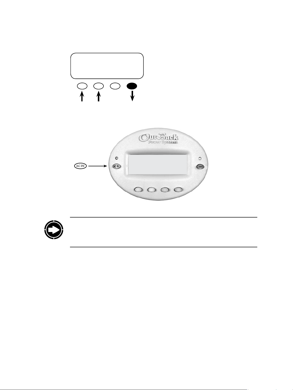
AC INPUT CONTROL
Currently:USE
DROP USE OK
MAIN------------------ 1:35:04p
SUM STATUS SETUP ADV
Push the <AC IN> hot key to view the AC status
and change to USE or DROP as needed. Pressing
the <OK> so key means you accept the conditions or mode shown on the screen.
NOTE: Even with HBX enabled, the user can issue manual DROP or USE commands using the
AC INPUT CONTROL found under the ACIN hot key. Once a manual command is issued,
the system will remain in that chosen command until the next HBX scheduled cycle normally
occurs.
Because GRID-USE Mode uses the DROP and USE commands, it cannot be enabled at the
same time as HBX Mode. Enabling GRID-USE will automatically disable HBX Mode
65
Page 66

Advanced Generator Start (AGS) Mode
is section applies to o-grid systems which regularly use generator-supplied power.
Why you may want it: Some systems include fuel-powered generators for either back-up or
regular usage. Advance Generator Start Mode sets the conditions under which a generator will
automatically start and stop, eliminating inconvenient manual starts and stops. If a user isn’t at
home or near the system, the generator will run anyway, in some cases keeping vital appliances
and motors running.
Advanced Generator Start (AGS) Mode utilizes the auxiliary (AUX) output found on each FX
and is compatible with any two- wire start generator. AGS oers a variety of conditions that
will start a generator by energizing the FX AUX output or the FLEXnet DC relay output.
AGS starts the generator anytime one or more of the Gen Start conditions are true and will
stop the generator only when all of the conditions are false except during a programmed Quiet
Time (normally at night when a noisy generator would be disturbing).
NOTE: Low Battery Cut Out overrides Quiet Time.
GenAlert is another way to automatically start a generator, but it does not oer the range of
programming options as AGS. AGS is a function of the MATE while GenAlert is a function of
the FX, which is programmed using the MATE. Information on the GenAlert function can be
found in the FX programming and operations manual.
NOTE: Choose either AGS or Gen Alert to automatically start your generator. Enabling AGS
overrides all AUX control functions of that particular inverter.
AGS can start a generator under the following variety of settings:
• Voltage Start
• Load Start
• Must Run
• State of Charge % Start (FLEXnet DC)
• Exercise
SAFETY WARNING: AGS can cause severe damage if the generator and battery bank are
not properly maintained.
66
Page 67

AGS Setup
To enter the AGS setup, go to the <ADV/MATE> screen:
MAIN-----------------------------------
9:57:32 A
SUM STATUS SETUP ADV
ADV----------------------------------
choose device:
FX CC DC MATE
ADV/SETTINGS/WARNING
changes made could
adversely affect
system performance
Press <INC> until 141 and
then press <ENTER>
ADV/PASSWORD------------- enter the password
132
ENTER INC DEC EXIT
ADV/MATE/PG1----------------------choose category:
HBX GRIDUSE AGS PG2
ADV/MATE/AGS-----------------------choose category:
QUIET VOLT
SETUP TIME START PG2
Press the <AGS> so key.
Press the <SETUP> so key.
67
Page 68

AGS Port
e AGS Setup menu contains the following general settings that dene the AGS routines.
e MATE uses the AUX output of an FX or FLEXnet DC relay to control the generator. e
MATE is connected to this FX either directly or through a HUB.
If a HUB is used:
• Use the <INC> and <DEC> so keys to set the AGS Port value to the HUB FX or FLEXnet
DC Port controlling the generator
If no HUB is used and the MATE is directly plugged into an FX, then the AGS Port needs to be
set to 0 (zero).
Example:
MATE/AGS/SETUP----------------ags port: 0
DOWN AGS INC DEC
MATE/AGS/SETUP------------------ags port: 3
DOWN AGS INC DEC
A MATE is connected to a HUB-10 that has four
FXs and three Charge Controllers connected to it.
e FXs are plugged into Ports 1 – 4, as labeled on
the HUB, and the Charge Controllers are plugged
into Ports 5 – 7. Any FX can have its AUX output
wired to a relay whose contacts are wired to the
starting circuitry of the generator. e AGS Port
must be set to the port of the chosen FX.
Aer setting the AGS Port, press the <DOWN>
so key. e next screen allows you to enable the
AGS Mode.
68
Page 69

AGS Enabled
AGS Control
ADV/MATE/AGS/SETUP------------
AGS enabled: NO
DOWN UP NO YES
ADV/MATE/AGS/SETUP-------------
AGS enabled: YES
DOWN UP NO YES
ADV/MATE/AGS/SETUP-------------
AGS control: MAN-OFF
DOWN UP CHANGE
is is the overall control for the AGS Mode. If
AGS is not enabled, none of the AGS settings
or controls will work. Enable the AGS rst by
pressing the YES so key and then establish your
settings.
Aer enabling the AGS Mode, press the
<DOWN> so key to continue to the AGS Control menu.
is screen allows the AGS Mode to be changed.
Pressing <CHANGE> brings up a screen that
allows the user to switch choose from three AGS
control modes sown below.
GEN START CONTROL
currently: MAN-OFF
OFF AUTO ON OK
is screen oers three options for AGS control:
• OFF manually de-energizes the FX AUX or
FLEXnet DC relay output and stops the generator regardless of any AGS setting; this is
displayed as MAN – OFF.
• AUTO allows AGS settings to start and stop the
generator automatically and is displayed as either AUTO – ON (when the AUX is activated),
or AUTO – OFF (when the AUX is deactivat-
ed).
• ON will manually energize the FX AUX output
and start the generator regardless of any AGS
setting; this is displayed as MAN – ON.
• OFF and ON are considered “manual” selections, hence the MAN-OFF and MAN-ON
screen displays.
69
Page 70
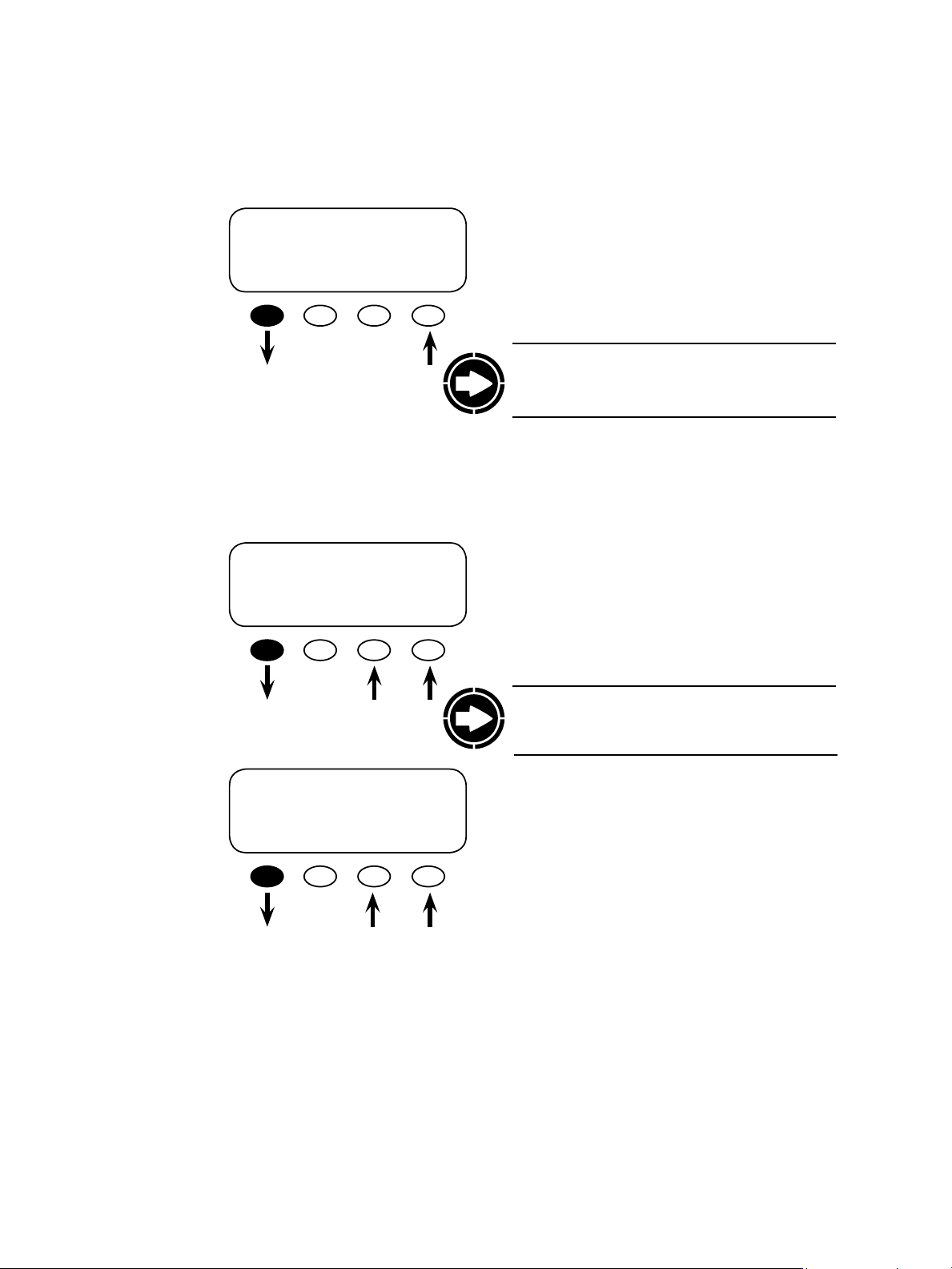
DC Genset
VDC Genstop
ADV/MATE/AGS/SETUP
dc genset NO
DOWN UP NO YES
ADV/MATE/AGS/SETUP-----
vdc genstop: 38.0 vdc
DOWN UP INC DEC
In this screen, YES means a DC generator is
present and the AGS routine, which normally
stops the generator upon the FX going to Float or
Silent, will instead stop the generator when the
vdc genstop setting is reached.
NOTE: If you have a generator that produces AC
voltage, maintain the NO status shown on this
screen.
Press the <DOWN> so key to go to the vdc
genstop screen.
is voltage setting will terminate a Voltage Start
command when the battery voltage remains above
it for 15 minutes regardless of the DC Genset
setting. e setting can be adjusted using the
<INC> and <DEC> so keys. Press the <DOWN>
so key to view the AGS fault time screen.
ADV/MATE/AGS/SETUP----AGS fault time 17
minutes
DOWN UP INC DEC
NOTE: e vdc genstop will turn o a generator
even if the dc genset on the previous screen says
<NO>.
AGS Fault Time is the period the generator is
given to connect to the FX system aer the AUX
output has been activated. If the generator fails
to connect and provide AC current, the MATE
displays an AGS error. e user can set this time
anywhere from 5-30 minutes by pressing the
<INC> and <DEC> so keys. Press the <DOWN>
so key to reach the cool down time screen.
70
Page 71

ADV/MATE/AGS/SETUP----cool down time 0
minutes
DOWN UP INC DEC
Aer the FX charging has been disabled, the cool
down time screen allows the user to adjust the
number of minutes the generator will cool down
before being shut o. is time should follow
the manufacturer’s recommendations. Press the
<DOWN> key to view the warm up time screen
ADV/MATE/AGS/SETUP----warm up time 0
minutes
DOWN UP INC DEC
End of AGS SETUP
UP TOP AGS
menu
e warm up time screen allow the user to
adjust the number of minutes the generator
will warm up before the FX charging begins.
is time should follow the manufacturer’s
recommendations. Press the <DOWN> key to
view the End of AGS SETUP time screen
NOTE: Cool down and warm up times are not
used when DC generator (dc genset) is selected.
NOTE: Cool down and warm up times are not
used when DC generator (dc genset) is selected.
In the End of the AGS SETUP screen Press
the <menu AGS> so key for more AGS
programming.
71
Page 72

Generators are an integral part of many renewable energy systems. Setting a generator’s start
and stop times and voltage set points can be confusing. e following test helps assure your
generator is properly functioning and the programming is accurate (AGS must be set up rst in
order to perform this test).
Before any further programming, conrm that the generator is working properly by manually
turning it on and then shutting it o.
Advanced Generator Start (AGS) Test
Quiet Time
GEN START CONTROL
currently: AUTO
OFF AUTO ON OK
e AGS test conrms the AGS function works and the generator has been enabled during
the AGS programming. Sometimes the GEN ALERT set points and properties get confused
with AGS and this test conrms the correct set points are used. GEN ALERT set points
should not be used as AGS set points. ese are two separate methods for starting a generator
automatically.
Why do you might want it: If Quiet Time Mode is set, the MATE will not allow most AGS
settings to start the generator during the Quiet Time window. is is usually set up during
night time when a running generator would be an annoyance. Quiet Times can be set
individually for weekday and weekend, and consist of a Quiet Time Start and a Quiet Time Stop.
PRESS TWICE:
• Brings up the GEN START CONTROL screen.
• Press the <ON> so key and wait for the
generator to go on.
• Press the <OFF> so key to shut the generator
o.
• Press the <AUTO> so key to put the generator
in AUTO mode
• Press the <OK> so key to return to the ADV/
MATE/AGS screen.
72
NOTE: e 2-minute Voltage set point (see page 78) will override Quiet Time settings. is is
necessary to prevent the battery from falling below an unacceptable voltage.
As with GRID-USE settings, if you set the START and STOP modes for the same time (for
example, 12:00 a.m. for each), each will be ignored. To program Quiet Time Mode, go to the
advanced MATE menu.
Page 73

PRESS <INC> UNTIL 141 AND THEN PRESS ENTER
MAIN-----------------------------------
9:57:32A
SUM STATUS SETUP ADV
ADV----------------------------------
choose device:
FX CC DC MATE
ADV/MATE/PG1---------------------
choose category
HBX GRIDUSE AGS PG2
ADV/SETTINGS/WARNING
changes made could
adversely affect
system performance
Go to the ADV/MATE screen and press the
<AGS> so key.
ADV/PASSWORD--------------------enter the password
ENTER INC DEC EXIT
131
Weekday Start
ADV/MATE/AGS---------------------choose category:
QUIET VOLT
SETUP TIME START PG2
ADV/MATE/AGS/QT-----------------weekday 12:00A
quiet time start
DOWN AGS CHANGE
Next, press the <QUIET TIME> so key.
weekday quiet time start is the beginning of the
Monday-Friday quiet time period. Most AGS
start conditions will be stopped during this
time. <CHANGE> adjusts the hour and minutes
settings.
73
Page 74

WEEKDAY QT START--------------adj hour 12:00A
DOWN INC DEC
<INC> and <DEC> adjust the weekday start
hours. When nished, press the <DOWN> so
key.
Weekday Stop
WEEKDAY QT START---------------adj min 12:00A
DOWN INC DEC
ADV/MATE/AGS/QT-----------------weekday: 12:00A
quiet time start
DOWN AGS CHANGE
ADV/MATE/AGS/QT-----------------weekday 12:00A
quiet time stop
DOWN AGS CHANGE
<INC> and <DEC> adjust the weekday start minutes. When nished, press the <DONE> so key.
is will return you to the ADV/MATE/AGS/QT
weekday quiet time start menu.
Press the <DOWN> so key to go to the weekday
quiet time stop screen.
weekday quiet time stop is the end of the quiet
time period for Monday-Friday. To change the
time, press the <CHANGE> so key and adjust
the hour and minute settings on the next screens
using the <INC> and <DEC> so keys. Proceed
through the adj hour and adj min screens in the
same manner described in the Weekday Start
section. Press the <DOWN> so key on the nal
ADV/MATE/AGS/QT weekday quiet time stop
screen to open the weekend screens.
74
Page 75

Weekend Start
ADV/MATE/AGS/QT-----------------weekend: 12:00A
quiet time start
DOWN UP CHANGE
weekend quiet time start is the beginning of the
quiet time period for Saturday and Sunday. Most
AGS start conditions will be stopped during this
time. Press the <CHANGE> so key to adjust the
hour and minutes settings.
WEEKEND QT START--------------adj hour 12:00A
DOWN INC DEC
WEEKEND QT START---------------adj min 12:00A
INC DEC DONE
ADV/MATE/AGS/QT-----------------weekend: 12:00A
quiet time start
DOWN UP CHANGE
<INC> and <DEC> adjust the hourly setting for
the WEEKEND QT START. Press the <DOWN>
so key when nished.
<INC> and <DEC> adjust the minutes setting for
the WEEKEND QT START. Press the <DONE>
so key when nished.
If you are satised with the weekend quiet time
start settings, press the <DOWN> so key and go
to the weekend stop screen.
75
Page 76
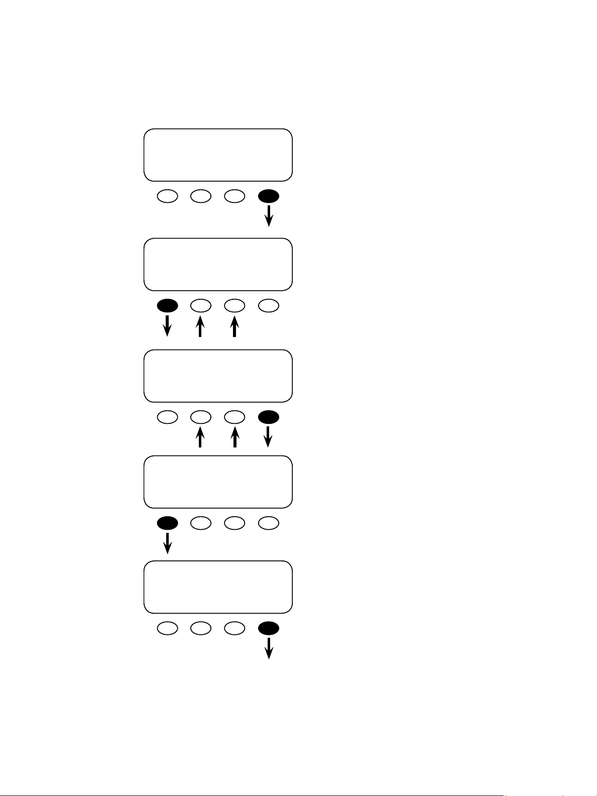
Weekend Stop
ADV/MATE/AGS/QT-----------------weekend 12:00A
quiet time stop
DOWN UP CHANGE
WEEKEND QT STOP----------------adj hour 12:00A
DOWN INC DEC
WEEKEND QT STOP----------------
adj min 12:00A
INC DEC DONE
weekend quiet time stop is the end of the quiet
time period for Saturday & Sunday. <CHANGE>
adjusts the hour and minutes settings.
<INC> and <DEC> adjust the hourly setting for
the WEEKEND QT STOP. Press the <DOWN>
so key when nished.
<INC> and <DEC> adjust the minute setting for
the WEEKEND QT STOP. Press the <DONE>
so key when nished.
76
ADV/MATE/AGS/QT--------------weekend 12:00A
quiet time stop
DOWN UP CHANGE
ADV/MATE/QUIET TIME-----------
end of QUIET TIME
menu
UP TOP AGS
If you are satised with the weekend quiet time
stop settings, press the <DOWN> so key and go
to the end of the quiet time menu.
Press the <AGS> so key to return to ADV/
MATE/AGS screen.
Page 77

Voltage Start
ere are three voltage start set points in AGS Mode that the user can adjust. Aer a generator
is started due to a Voltage Start setting, it will be stopped when the FX completes the absorb
charge or based on the VDC Genstop setting in the AGS Setup menu previously explained.
NOTE: If the DC Genset is set to YES, the generator will only stop aer the battery voltage has
reached the VDC Genstop voltage for 15 minutes.
ADV/MATE/AGS-----------------------Choose category:
QUIET VOLT
SETUP TIME START PG2
24-Hour Voltage Set Point
ADV/MATE/AGS/VSTART----------volt start 24.4 vdc
24 hr setting
DOWN AGS INC DEC
2-Hour Voltage Set Point
ADV/MATE/AGS/VSTART-----------volt start 23.6 vdc
2 hr setting
DOWN UP INC DEC
To get to the Voltage Start screen, press the
<VOLT START> so key on the ADV/MATE/
AGS screen.
If the battery voltage falls below this set point, a 24
hour timer starts counting down. Upon reaching
zero, a start command is sent to the generator
unless it is currently Quiet Time. To change the
default settings, use the <INC> and <DEC> so
keys. When nished, press the <DOWN> so key
to go to the volt start 2 hr setting screen.
If the battery voltage falls below this set point, a 2
hour timer starts to count down. Aer reaching
zero, a start command is sent to the generator
unless it is currently Quiet Time. To change the
default settings, use the <INC> and <DEC> so
keys. When nished, press the <DOWN> so key
to go to the volt start 2 min setting screen.
77
Page 78

2-Minute Voltage Set Point
Load Start
ADV/MATE/AGS/VSTART----------volt start 22.0 vdc
2 min setting
DOWN UP INC DEC
If the battery voltage falls below this set point, a
2-minute timer starts to count down. Upon reaching zero, a start command is sent to the generator
even if it is currently Quiet Time. Use the <INC>
and <DEC> so keys to change the default settings. When nished, press the <DOWN> so key
to go to the end of VOLTAGE START menu.
ADV/MATE/AGS/VSTART----------end of VOLTAGE START menu
UP TOP AGS
Press the <AGS> so key to return to ADV/
MATE/AGS
Why you might want it: Instead of the generator starting only at preset times or according to
battery voltage conditions, Load Start allows it to start because the demand for electricity is
high. is should prevent the batteries from being depleted. As soon as the demand decreases
and the batteries can adequately fulll it, the generator will shut o.
Load Start will start a generator whenever the total system AC Load exceeds the set point for
the programmed amount of time. e generator will then be stopped when the AC load has
dropped below a Load Stop set point for a programmed amount of time.
When the generator is running because of Load Start, the FX system will charge the batteries.
is charge might not be completed if the generator is disconnected because of Load Stop.
NOTE: Large instantaneous loads can still overcurrent the inverter prior to the generator
starting and getting in sync with the inverter.
78
Page 79

To open the Load Start screen:
Load Start KW
ADV/MATE/AGS----------------------choose category
QUIET VOLT
SETUP TIME START PG2
ADV/MATE/AGS/PG2---------------choose category
LOAD MUST
PG1 START RUN PG3
ADV/MATE/AGS/LS------------------
load start 0 kw
DOWN AGS INC DEC
Go to the ADV/MATE/AGS screen and press the
<P2> so key.
At the ADV/MATE/AGS/PG2 screen, press the
<LOAD START> so key.
In the load start kw screen, an AGS start
command will be issued when the total AC load
of all the FXs connected to the MATE exceeds
this setting for the load start delay (next screen)
time. A zero value disables any load start function.
<INC> and <DEC> adjusts this setting between
1 – 50kW. Aer the value has been set, press the
<DOWN> so key to get to the load start delay
screen.
79
Load Start Delay
ADV/MATE/AGS/LS-----------------load start 1 min
delay
DOWN UP INC DEC
is setting is the delay time that the total system
AC load must remain above the load start kw
setting (see previous screen), before the generator
is started. It is adjustable from 1 to 240 minutes
using the <INC> and <DEC> so keys. Aer
making any adjustments to the delay time, press
the <DOWN> so key to go to the load stop kw
screen.
Page 80

Load Stop KW
Load Stop Delay
ADV/MATE/AGS/LS-----------------
load stop 0 kw
DOWN UP INC DEC
ADV/MATE/AGS/LS---------------load stop 1 min
delay
DOWN UP INC DEC
ADV/MATE/AGS/LS--------------end of the LOAD START menu
An AGS stop command will be issued when the
total AC load of all the FXs connected to the
MATE falls below this setting for the amount of
time set with load stop delay (next screen) as long
as the generator was started due to Load Start.
is setting excludes any FX charger current
for its AC load calculation. e setting can be
changed using the <INC> and <DEC> so keys.
Pressing the <DOWN> so key leads to the load
stop delay screen.
is setting is the delay time the total system AC
load must remain below the Load Stop kw before
the generator is stopped. It is adjustable from 1 to
240 minutes using the <INC> and <DEC> keys.
Pressing the <DOWN> so key leads to the end of
the VOLTAGE START menu screen.
Pressing the <AGS> so key returns the ADV/
MATE/AGS/PG2 screen
UP TOP AGS
80
Page 81

Must Run
Why you might want it: In time, a user can determine patterns in energy usage and demands
on batteries. Must Run times the generator usage to the heaviest user demands during a day,
thus avoiding depleting the batteries or requiring a long recharging period. is might happen
in the mornings or early evenings when a family’s power demand is higher.
Must Run Time is a daily time period when the MATE commands the generator to run. Must
Run Times can be set individually for weekdays and weekends and consist of a must run start
time and a must Run stop time. Setting must run start and stop times to the same time disables
the Must Run function. To go to the Must Run screens, press the <Must Run> so key on the
ADV/MATE/AGS/P2 screen.
Weekday Start
ADV/MATE/AGS/PG2--------------choose category
LOAD MUST
PG1 START RUN PG3
ADV/MATE/AGS/MR---------------weekday 12:00A
must run start time
DOWN AGS CHANGE
WEEKDAY MR START
adj hour 12:00A
DOWN INC DEC
From the ADV/MATE/AGS/PG2 screen, press
the <MUST RUN> so key and open the ADV/
MATE/AGS/MR weekday must run start time
screen.
weekday must run start time is the beginning of
the time period Monday-Friday that the generator
will be forced to run. Press <CHANGE> to adjust
the hour and minutes settings using the <INC>
and <DEC> so keys.
Adjust the weekday must run start time minutes
with the <INC> and <DEC> so keys. Press the
<DOWN> so key to view the adj min screen.
81
WEEKDAY MR START
adj min 12:00A
INC DEC DONE
Aer the minutes have been set, press the
<DONE> so key to return to the ADV/MATE/
AGS/MR weekday must run start time screen.
Page 82

Weekday Stop
ADV/MATE/AGS/MR---------------weekday: 12:00A
must run start time
DOWN AGS CHANGE
weekday must run stop time is the end of the Must
Run time period for Monday-Friday. Press the
<DOWN> so key to go to the weekday must run
stop screen.
ADV/MATE/AGS/MR-----------------weekday: 12:00A
must run stop time
DOWN UP CHANGE
WEEKDAY MR STOP
adj hour 12:00A
DOWN INC DEC
WEEKDAY MR STOP
adj min 12:00A
INC DEC DONE
To adjust the start time hour and minute settings,
press the <CHANGE> so key.
Adjust the hours using the <INC> and <DEC>
so keys. When nished, press the <DOWN> so
key to adjust the minutes.
Adjust the minutes using the <INC> and <DEC>
so keys. When nished, press the <DONE> so
key to return to the ADV/MATE/AGS/MR week-
day must run stop time screen.
82
Page 83

Weekend Start
ADV/MATE/AGS/MR---------------weekday 12:00A
must run stop time
DOWN UP CHANGE
ADV/MATE/AGS/MR----------------weekend 12:00A
must run start time
DOWN UP CHANGE
WEEKEND MR START
adj hour 12:00A
DOWN INC DEC
Press the <DOWN> so key in the ADV/MATE/
AGS/MR screen to adjust the weekend must run
start time.
weekend must run start time is the beginning
of the time period, Saturday and Sunday, that
the generator will be forced to run. To adjust
the weekend must run start time, press the
<CHANGE> so key.
Adjust the weekend must run start time hours
using the <INC> and <DEC> so keys. Press the
<DOWN> so key when nished.
83
WEEKEND MR START
adj min 12:00A
INC DEC DONE
Adjust the weekend must run start minutes us-
ing the <INC> and <DEC> so keys. Press the
<DONE> so key to return to the ADV/MATE/
AGS/MR weekend must run stop time screen when
nished.
Page 84

Weekend Stop
ADV/MATE/AGS/MR----------------weekend 12:00A
must run start time
DOWN UP CHANGE
Press the <DOWN> so key to go to the ADV/
MATE/AGS/MR weekend must run stop screen.
ADV/MATE/AGS/MR----------------weekend 12:00A
must run stop time
DOWN UP CHANGE
WEEKEND MR STOP
adj hour 12:00A
DOWN INC DEC
WEEKEND MR STOP
adj min 12:00A
INC DEC DONE
weekend must run stop time is the end of the must
run time period for Saturday and Sunday. Press
<CHANGE> to adjust the hour and minutes
settings.
Adjust the hour settings using the <INC> and
<DEC> so keys. Press the <DOWN> so key
when nished to go to adj min screen to change
the minutes.
Adjust the minutes settings using the <INC>
and <DEC> so keys. When nished, press the
<DONE> so key to return to the ADV/MATE/
AGS/MR weekend: must run stop time screen.
84
ADV/MATE/AGS/MR---------------weekend 12:00A
must run stop time
DOWN UP CHANGE
To proceed to the end of MUST RUN menu, press
the <DOWN> so key.
Page 85

ADV/MATE/AGS/MR-------------- end of MUST RUN menu
UP TOP AGS
To proceed to the ADV/MATE/AGS/PG2 screen,
press the <AGS> so key
ADV/MATE/AGS/PG2----------------choose category
LOAD MUST
PG1 START RUN PG3
ADV/MATE/AGS/PG3---------------choose category
%SOC
PG2 START TIMERS PG4
ADV/MATE/AGS/%SOC-------------%SOC start %
DOWN AGS INC DEC
Press the <P3> so key to access the ADV/MATE/
AGS/PG3 screen which includes the EXERCISE
option.
Press the <%SOC> so key.
With a FLEXnet DC, a user can start a generator
based on a battery state of charge rather than its
voltage, which can be less accurately inteprepeted
depending on loads and surges. Use the <INC>
and <DEC> so keys to adjust this value. Press
the <DOWN> so key to view the %SOC stop
screen.
85
ADV/MATE/AGS/%SOC-------------%SOC stop 90%
DOWN AGS INC DEC
ADV/MATE/AGS/%SOC--------------
end of %SOC
START menu
UP TOP AGS
A user can stop a generator based on the
percentage of the battery’s state of charge using
<INC> and <DEC> so keys.
Press the <AGS> so key to view the ADV/MATE/
AGS/PG3 screen.
Page 86

ADV/MATE/AGS/PG3--------------choose category
%SOC
PG2 START TIMERS PG4
ADV/MATE/AGS/TIMERS-----------agsstate 0
DOWN AGS
ADV/MATE/AGS/TIMERS ----------
agsgenfault 0
DOWN UP
ADV/MATE/AGS/TIMERS---------
24 hr 1440 min
vs time
DOWN UP
Press the <TIMERS> so key to view the
various AGS timer-related screens.
e agsstate screen displays a numeric value
corresponding to why the generator is or is not
running. is is a diagnostic feature for OutBack
troubleshooting purposes. Press the <DOWN>
so key to view the next TIMER screen.
AGS state can be one or more of the following
numbers:
Manual Start 128
Exercise 64
Time of Day 32
Load Start 16
Voltage 24hr/2hr 8
Voltage 2min 4
SOC Start 2
An AGS state of 128 means that AGS is active
because of a manual start. More then one reason
can be true at any one time (e.g., AGS state of 20
would be load start and 2 min voltage timer). e
generator will be running any time AGS state is
greater then 0.
e agsgenfault screen displays three states:
• 0 or no generator fault
• 1 indicates the generator did not start and there
is no AC input aer ve minutes
• 2 indicates the generator started, but then
stopped (e.g., it ran out of fuel)
86
ADV/MATE/AGS/TIMERS---------
2hr vs time 120 min
DOWN UP
ADV/MATE/AGS/TIMERS ---------
2 min 2 min
vs time
DOWN UP
Press the <DOWN> so key to proceed.
e 24 hr vs time screen counts down the minutes,
starting at 1440, of the 24-hour voltage start set
point. Aer the battery voltage has fallen below its
24-hour set point, the timer starts and is displayed
here. Pressing the <DOWN> so key brings up
the 2hr vs time screen.
e 2hr vs time 120 min screen counts down
the 2-hour voltage start set point. Pressing the
<DOWN> so key leads to the 2 min vs time
screen.
e 2 min vs time screen counts down the
2-minute voltage start set point. Pressing the
<DOWN> so key leads to the lsstart timer
screen.
Page 87

ADV/MATE/AGS/TIMERS ---------
lsstart timer 0 min
DOWN UP
is screen displays the load start delay timer
which is adjustable up to 240 minutes, counting
down. e user determines how many minutes
the AC loads must remain above the load start
kw set point before starting the generator. Press
the <DOWN> so key to view the next TIMERS
screen.
ADV/MATE/AGS/TIMERS---------
lsstop timer 0 min
DOWN UP
ADV/MATE/AGS/TIMERS---------
vdcstop timer 0 min
DOWN UP
ADV/MATE/AGS/TIMERS---------
exstop timer 0 min
DOWN UP
e lsstop timer screen counts down the time the
AC load must remain below the load stop kw before the generator stops. Press the <DOWN> so
key to view the vdcstop timer screen.
e vdcstop timer counts down the amount of
time a DC generator is allowed to run. Press
the <DOWN> so key to view the last TIMERS
screen.
e exstop timer screen displays the amount of
time the generator runs during an exercise period
(1-240 minutes). Press the <DOWN> so key to
open the end of TIMERS screen.
87
ADV/MATE/AGS/TIMERS ----------
end of TIMERS
menu
UP TOP AGS
is is the nal TIMERS screen. Press the <AGS>
so key to view the nal AGS screen.
Page 88

Generator Exercise
ADV/MATE/AGS/PG3--------------choose category
Press the <PG4> so key
%SOC
PG2 START TIMERS PG4
ADV/MATE/AGS/PG5-------------choose category
PG2 EXERCISE ADV
Press the <EXERCISE> so key.
is takes you to the ADV/MATE/AGS/EX (exercise) screen for running a lightly used
generator at least one day a month to assure it’s in good working order (see next section).
Why you might want it: Exercising a generator prolongs its life and dependability.
Regularly running a generator keeps engine components lubricated, expels excess moisture,
charges the starting battery, and helps prevent carbon build-up. Consult your generator owner’s
manual to nd the manufacturer’s recommendations for appropriate length and frequency of
exercise periods and what load to run during the exercise periods.
An Exercise time can be set by choosing a day of the week (Sun – Sat), a start time of day
(12AM – 11:59PM), and an exercise period (1 – 240 minutes). e generator will run once a
month at this chosen time during the rst occurrence of the chosen day.
Sample Generator Exercise Schedule
Day: Saturday
Time: 10:00 a.m.
Exercise Period: 15 minutes
A een minute exercise period with loads running
is a good starting point for most generators.
88
Page 89

Exercise Start Day (exstartday)
Ex Start Time
ADV/MATE/AGS/EX----------exstartday
DOWN AGS INC DEC
ADV/MATE/AGS/EX------------------
ex start time 12:00A
DOWN UP CHANGE
EX START TIME
adj hour 12:00A
DOWN INC DEC
Use the <INC> or <DEC> so keys to choose the
day (Sunday-Saturday) of the week to exercise
the generator. To disable the exercise function,
push either the <INC> or <DEC> so keys until a
broken line (--) appears. Press the <DOWN> so
key to go to the EX START TIME screen which
sets the exercise start time.
is setting controls the daily exercise start time.
Press the <CHANGE> so key to adjust the hour
and minute settings using the <INC> and <DEC>
so keys on the hour and minute screens.
Aer adjusting the exercise start time hour, press
the <DOWN> so key and go to the adj min
screen.
EX START TIME
adj min 12:00A
INC DEC DONE
Ajust the minutes and then press the <DONE>
so key to return to the ADV/MATE/AGS/EX ex
start time screen
89
Page 90

Ex Period
ADV/MATE/AGS/EX-----------------ex start time 12:00A
DOWN UP CHANGE
ADV/MATE/AGS/EX------------------
ex period 30 min
DOWN UP INC DEC
ADV/MATE/AGS/EX----------------- end of
exercise menu
UP TOP AGS
Press the <DOWN> so key. is takes you to
the ADV/MATE/AGS/EX ex period screen, which
allows you to set the number of minutes your
generator will run during its exercise period.
e exercise period screen allows you to set the
length of the exercise period using the <INC>
and <DEC> so keys. e MATE oers a range
of 1-240 minutes for this period, but check your
generator manufacturer’s recommendations
before setting this period. Press the <DOWN>
so key to exit this screen and go to the ADV/
MATE/AGS/EX end of exercise menu screen.
90
Page 91

Grid-Use Mode
Why you might want it: Grid-connected systems make use of utility-supplied power. e
MATE’s Grid-Use Mode allows the user to pre-determine the time periods it uses the grid.
NOTE: e FX’s default settings are for a generator-supported system. If your system includes
a utility’s grid, set the FX to Grid by going to SETUP/FX/INPUT ac transfer control and
pressing the <GRID> so key.
MAIN---------------------------------- 8:25:04A
SUM STATUS SETUP ADV
SETUP/FX/INPUT---------------P00
ac transfer Grid
control
DOWN GRID GEN PORT
Grid-Use Mode allows programing the times the FX system connects to an AC input source
and enables the <USE> mode. e time and date must be accurately programmed for Grid-Use
mode to function properly.
Grid-Use Mode is programmed separately for weekday and weekend connect times. Care must
be taken when programming weekday and weekend times that encompass <USE> periods past
midnight (12:00 am). e user must take into account weekday <USE> periods that will end
on a Saturday.
Example #1:
Weekday Start-6:00 p.m. Press <INC> and <DEC> so keys as
needed to change set points
ADV----------------------------------choose a device:
FX CC DC MATE
SETUP/FX------------------------choose category:
SRCH INPUT MAIN
91
Weekend Start-12:00 a.m. Weekend Stop-12:00 a.m.
e weekend USE period has been le at its default (12:00 a.m.). Any time that a Start time
equals a Stop time, no action will be taken and the time period is ignored. e above settings
will have the following results:
• Monday—Friday evenings at 6 p.m., the MATE issues a USE command to the FX allowing
the AC input source to be used.
• Monday-Friday mornings at 6 a.m., a DROP will be issued.
• On Friday evening at 6 p.m., a USE will be issued but since the Weekend Start and Stop times
are equal, the weekend use time is disabled; no DROP will be issued until Monday morning
at 6 a.m.
Page 92

Example #2:
Weekday Start-6:00 p.m. Weekday Stop-6:00 a.m.
Weekend Start-4:00 p.m. Weekend Stop-8:00 a.m.
• Monday—ursday evenings at 6:00 p.m., the MATE will issue a USE command to the FX
allowing the AC input source to be used.
• Monday—Friday at 6:00 a.m., a <DROP> will be issued. On Friday evening at 6:00 p.m., a
USE will be issued.
• e following morning is a weekend (Saturday) so a DROP command will be issued at 8:00
a.m. During Saturday aernoon at 4:00 p.m., the FX will USE again until Sunday morning at
8:00 a.m. On Sunday evening at 4:00 p.m., a USE time period will start, ending on Monday
morning at 6:00 a.m.
NOTE:
• If the battery voltage falls below the FX’s Low Battery Cut-O voltage, the FX will
automatically connect to the AC input source regardless of the GRID-USE time of day setting.
• Because GRID-USE Mode uses the DROP and USE commands, it cannot be enabled at the
same time as HBX Mode. Enabling GRID-USE will automatically disable HBX Mode.
• GRID-USE Mode only allows one Drop and Use per day. GRID-USE can be aected by the
MATE not automatically adjusting its clock for Daylight Savings Time.
• A START time that equals a STOP time disables a change during that period (weekdays
or weekends). If disabled, the current USE or DROP command will continue through the
disabled period. If both the weekday and weekend periods have START and STOP times that
are the same, respectively, the GRID-USE Mode will be completely disabled.
To enter grid use mode:
MAIN
9:57:32 A
SUM STATUS SETUP ADV
ADV/MATE----------------------------choose category:
HBX GRIDUSE AGS PG2
ADV/MATE/GRIDUSE--------------weekend 12:00A
gridusestart
DOWN ADV OFF ON
ADV/SETTINGS/WARNING
changes made could
adversely affect
system performance
ADV/MATE/GRIDUSE---------------griduse enable: Off
DOWN ADV OFF ON
ADV/MATE/GRIDUSE---------------weekend 12:00A
griduse stop
DOWN UP CHANGE
Press until 141 and then press enter.
ADV/PASSWORD----------------- enter the password
132
ENTER INC DEC EXIT
ADV/MATE/GRIDUSE---------------weekday 12:00A
griduse start time
DOWN UP CHANGE
ADV---------------------------------choose device:
FX CC DC MATE
ADV/MATE/GRIDUSE-------------weekday 12:00A
griduse stop time
DOWN UP CHANGE
92
Page 93

ADV-----------------------------------choose device:
FX CC DC MATE
On the ADV menu, push the <MATE> so key.
NOTE: Set all the weekday and weekend timing rst before turning the GRID-USE Mode on.
e GRID-USE settings can be accessed by pressing the <DOWN> so key.
Weekday Grid-Use Start
ADV/MATE-------------------------choose category:
HBX GRIDUSE AGS PG2
ADV/MATE/GRIDUSE--------------griduse enable: Off
DOWN ADV OFF ON
Press the <GRIDUSE> so key on the <ADV/
MATE> screen.
e rst GRID-USE screen to appear is the
griduse enable screen. is screen turns GRIDUSE mode ON or OFF.
93
ADV/MATE/GRIDUSE--------------weekday 12:00A
griduse start time
DOWN UP CHANGE
is setting is the time during the week (Monday–
Friday) that a USE will be issued to the FX system,
allowing it to connect to the AC input source.
e time displayed is the default setting. To
change the time on the adj hour screen, press the
<CHANGE> so key
Page 94

WEEKDAY GRIDUSE START
adj hour 12:00A
DOWN INC DEC
<INC>and <DEC> set the hour to the desired
time. Press <DOWN> to access the adj min
screen.
Weekday Grid-Use Stop
WEEKDAY GRIDUSE START
adj min 12:00A
INC DEC DONE
ADV/MATE/GRIDUSE----------------weekday 12:00A
griduse start time
DOWN UP CHANGE
ADV/MATE/GRIDUSE---------------weekday 12:00A
griduse stop time
DOWN UP CHANGE
<INC> and <DEC> set the minutes to the desired
time. Press the <DONE> so key to return to the
weekday griduse start screen.
Press the <DOWN> so key to access the ADV/
MATE/GRIDUSE weekday grid-use stop screen.
e WEEKDAY GRID-USE STOP setting is the
time during the week (Monday-Friday) that a
DROP will be issued to the FX system, forcing a
disconnect from the AC input source. e time
displayed is the default setting. To change the
time, press the <CHANGE> so key and adjust
the hour and minute settings on the next screens
using the <INC> and <DEC> so keys. Proceed
through the Adjust Hour (adj hour) and Adjust
Minutes (adj min) screens in the same manner
described in the weekday grid-use start section.
94
Page 95
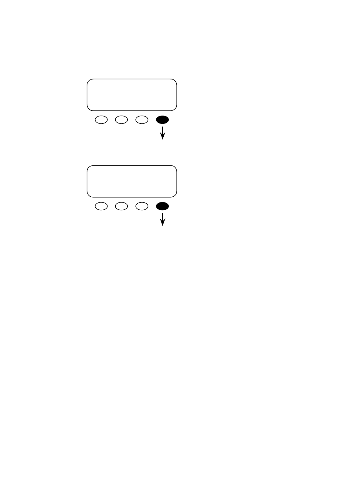
Weekend Grid-Use Start
Weekend Grid-Use Stop
ADV/MATE/GRIDUSE---------------weekend 12:00A
gridusestart
DOWN ADV OFF ON
ADV/MATE/GRIDUSE---------------weekend 12:00A
griduse stop
DOWN UP CHANGE
is setting is the time during the weekend (Saturday and Sunday) that a <USE> will be issued to
an FX system, allowing the FX to connect to the
AC input source. e time displayed is the default
setting. To change the time press the <CHANGE>
so key and adjust the time as you would for a
weekday setting.
is setting is the time during the weekend (Saturday and Sunday) that a DROP will be issued
to the FX system, forcing the FXs to disconnect
from the AC input source. e time displayed is
the default setting. To change the time press the
<CHANGE> so key and adjust the time as you
would for a weekday setting.
Aer setting the START and STOP times, scroll
back to the rst GRID-USE screen using the
<UP> so key. Press the <ON> so key to activate
GRID-USE Mode.
95
Page 96

MATE DEFAULTS
e MATE comes with factory default settings for its various functions. Many of these can be
changed depending on a user’s preferences. To return the MATE to its default settings, go to
the ADV/MATE/DEFAULT screen and press the <RESET> so key. Press the <YES> so key
in the ADV/MATE/RESET ARE YOU SURE? screen to reset the default values.
ADV-------------------------------------
choose device:
FX CC DC MATE
ADV/MATE/DEFAULT----------------reset MATE to
factory default
RESET NO
MATE SETUP Default Values
SETUP/MATE/CNT----------------contrast: 30%
BACK INC DEC
ADV/MATE/PG1--------------------choose category:
HBX GRIDUSE AGS PG2
ADV/MATE/RESET-----------------ARE YOU SURE?
YES NO
SETUP/MATE/GLOW/LEVEL----backlight 100%
BACK INC DEC
ADV/MATE/PG2------------------choose category:
PG1 DEFAULTS ADV
MAIN------------------------------ 9:20:09A
SUM STATUS SETUP ADV
SETUP/MATE/GLOW/MODE----current mode AUTO
BACK OFF AUTO ON
96
SETUP/MATE/GLOW/Time--------glow off 5 mins
time
BACK INC DEC
SETUP/MATE/SUM ROLL---------sum screen: 8 secs
roll rate
BACK INC DEC
SETUP/MATE/SUM/TYPE---------summary Roll
screen type
BACK INC DEC
SETUP/MATE/SUM/TIME---------sum screen: 20 Mins
delay time
BACK INC DEC
Page 97

MATE ADVANCED Default Values
• HBX Menu
ADV/MATE/HBX-------------------hbx-use 12.0 vdc
grid setpoint
DOWN ADV INC DEC
ADV/MATE/HBX--------------------hbx-drop 01.0 hrs
grid delay
DOWN ADV INC DEC
• Griduse Menu
ADV/MATE/GRIDUSE----griduse enable: OFF
DOWN ADV OFF ON
ADV/MATE/HBX-------------------hbx-use 01.0 hrs
grid delay
DOWN ADV INC DEC
NOTE: e MATE’s hbx-use grid setpoint screen vdc value will
equal the battery voltage of the system it’s connected to. In
this case, it reects 12 VDC batteries.
NOTE: For a 24 VDC battery, the hbx-drop grid setpoint is
26.0 vdc; for 32 VDC, the value is 34.7 for 36 VDC, it’s 39.0
vdc; and for 48 VDC, the value will be 52 vdc.
ADV/MATE/GRIDUSE----weekday 12:00A
griduse start time
DOWN UP CHANGE
ADV/MATE/HBX-------------------hbx-drop 13.0 vdc
grid setpoint
DOWN ADV INC DEC
ADV/MATE/GRIDUSE----weekday 12:00A
griduse stop time
DOWN UP CHANGE
ADV/MATE/GRIDUSE----weekend 12:00A
griduse start time
DOWN UP CHANGE
• AGS SETUP Menu
MATE/AGS/SETUP-----------------ags port: 0
DOWN AGS INC DEC
ADV/MATE/AGS/SETUP-------------dc genset:: No
DOWN UP NO YES
ADV/MATE/AGS/SETUP-----------cool down time 0
minutes
DOWN UP INC DEC
ADV/MATE/GRIDUSE----weekend 12:00A
griduse stop time
DOWN UP CHANGE
ADV/MATE/AGS/SETUP-----------AGS enabled: No
DOWN UP NO YES
ADV/MATE/AGS/SETUP-----------vdc genstop 19.0 vdc
DOWN UP INC DEC
ADV/MATE/AGS/SETUP------------warm up time 0
minutes
DOWN UP INC DEC
ADV/MATE/AGS/SETUP-----------AGS control: MAN-OFF
DOWN UP CHANGE
ADV/MATE/AGS/SETUP------------ags fault 17 min
time
DOWN UP INC DEC
97
Page 98
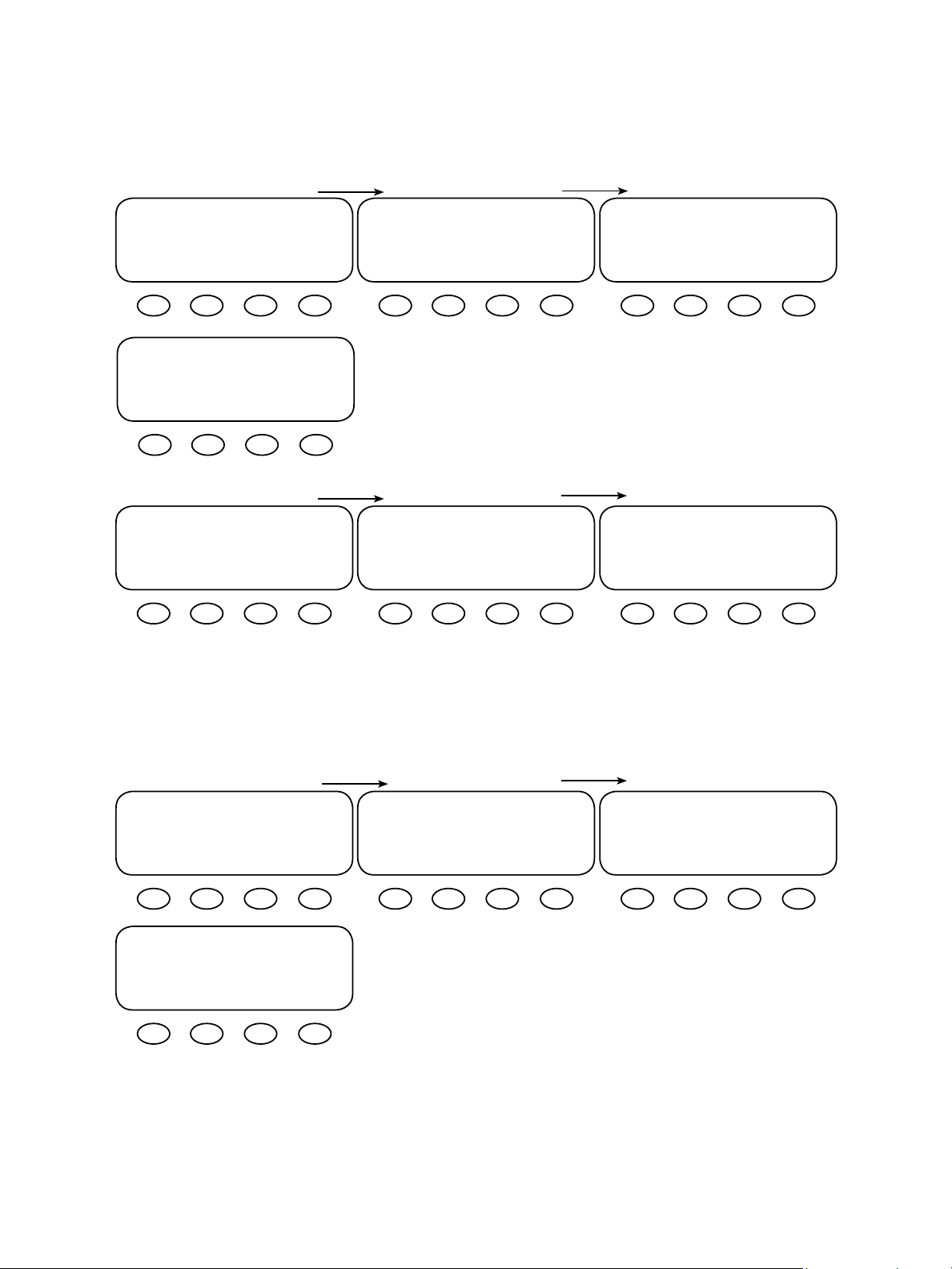
• AGS QUIET TIME Menu
ADV/MATE/AGS/QT---------------weekday 12:00A
quiet time start
DOWN AGS CHANGE
ADV/MATE/AGS/QT-----------------weekend 12:00A
quiet time stop
DOWN UP CHANGE
• AGS VOLT START Menu
ADV/MATE/AGS/VSTART---------volt start 12.2 vdc
24 hr setting
DOWN AGS INC DEC
Volt start 24 hr setting:
24 VDC system = 24.4 vdc
32 VDC system = 32.6 vdc
36 VDC system = 36.6 vdc
48 VDS system = 48.8 vdc
ADV/MATE/AGS/QT---------------weekday 12:00A
quiet time stop
DOWN UP CHANGE
ADV/MATE/AGS/VSTART----------volt start 11.8 vdc
2 hr setting
DOWN AGS INC DEC
Volt start 2 hr setting:
24 VDC system = 23.6 vdc
32 VDC system = 31.5 vdc
36 VDC system = 35.4 vdc
48 VDS system = 47.2 vdc
ADV/MATE/AGS/QT-----------------weekend 12:00A
quiet time start
DOWN UP CHANGE
ADV/MATE/AGS/VSTART-----------volt start 11.0 vdc
2 min setting
DOWN AGS INC DEC
Volt start 2 min setting:
24 VDC system = 22.0 vdc
32 VDC system = 29.3 vdc
36 VDC system = 33.0 vdc
48 VDS system = 44.0 vdc
98
• AGS VOLT START Menu
ADV/MATE/AGS/LS----------------load start 0 kw
DOWN AGS INC DEC
ADV/MATE/AGS/LS----load stop 1 min
delay
DOWN AGS INC DEC
ADV/MATE/AGS/LS----------------load start 1 min
delay
DOWN AGS INC DEC
ADV/MATE/AGS/LS----------------load stop 0 kw
DOWN AGS INC DEC
Page 99

• AGS MUST RUN Menu
ADV/MATE/AGS/MR---------------weekday 12:00A
must run start time
DOWN AGS CHANGE
ADV/MATE/AGS/MR----------------weekend 12:00A
must run stop time
DOWN UP CHANGE
• AGS EXERCISE Menu
ADV/MATE/AGS/EX----------------exstartday ----
DOWN AGS INC DEC
• AGS TIMERS Menu
ADV/MATE/AGS/MR---------------weekday 12:00A
must run stop time
DOWN UP CHANGE
ADV/MATE/AGS/EX----------------ex start time 12:00A
DOWN UP CHANGE
ADV/MATE/AGS/MR---------------weekend 12:00A
must run start time
DOWN UP CHANGE
ADV/MATE/AGS/EX----------------ex period 15 min
DOWN UP INC DEC
ADV/MATE/AGS/TIMERS
agsstate 0
DOWN AGS
ADV/MATE/AGS/TIMERS
24hr vs time 120 min
DOWN UP
ADV/MATE/AGS/TIMERS
1sstop timer 0 min
DOWN AGS
ADV/MATE/AGS/TIMERS
agsgenfault 0
DOWN UP
ADV/MATE/AGS/TIMERS
2 min 2 min
vs time
DOWN UP
ADV/MATE/AGS/TIMERS
vdcstop timer 0 min
DOWN UP
ADV/MATE/AGS/TIMERS
24hr 1440 min
vs time
DOWN UP
ADV/MATE/AGS/TIMERS
1sstart timer 0 min
DOWN UP
ADV/MATE/AGS/TIMERS
exstop timer 0 min
DOWN UP
99
Page 100

8 MATE Menu Map
100
 Loading...