

Page 1
Mate Serial Communications Guide
This guide is only relevant to Mate Code Revs. of 4.00 and greater
For additional information contact matedev@outbackpower.com
Mate Serial Communication Guide Copyright 2007 © OutBack Power Systems, Inc.
19009 62nd Ave NE, Arlington WA 98223 USA
Page 1 of 20 Rev 4.04 10/21/08 Tel 360 435 6030 Fax 360 435 6019
Page 2

Revision History
Revision 2.0:
1. Added revision history.
2. Corrected some typos.
3. Added more typos.
4. Added Hub description to Mate Overview.
5. Added Baud rate description to Hardware section.
6. Changed inverter address description in FX Status Page.
7. Added to FX mode descriptions in FX Status Page.
8. Added to AC mode descriptions in FX Status Page.
9. Changed bit 5 warning mode description in FX Status Page.
10. Added MX Status Page.
11. Changed the description in Commands section.
12. Added information to Command Timing.
Revision 3.0:
1. Added Grid-Tie comm. information to FX Status Page section.
a. Changed FX operational mode bytes to reflect GT info.
b. Removed GT info from AC mode bytes.
Revision 3.01
1. Added to the Misc. byte definition for the FX (pg. 8)
a. Added note to divide all currents by 2 if the Unit has 230VAC output.
Revision 3.02 1. Clarified MX60 chksum calculations. (pg .12)
Revision 4.00 1. Add FLEXnet DC
Revision 4.01 1. Added battery temperature to FLEXnet DC.
2. Added Accumulated AH and kWH for all shunts to FLEXnet DC.
3. Added days since full to FLEXnet DC.
4. Added daily AH field MX.
Revision 4.02 1. Added clarifications for FLEXnet DC status bytes.
Revision 4.03 1. Minor naming convention updates.
2. Fixed reversed FNDC relay mode text.
3. Fixed reversed table entries “Relay State” and “Relay Mode” in Figure 14.
4. Added Net AH and kWH to FNDC extra data stream.
5. Added manual mode value to Figure 10.
Revision 4.04 1. Removed manual mode value from Figure 10.
Mate Serial Communication Guide Copyright 2007 © OutBack Power Systems, Inc.
19009 62nd Ave NE, Arlington WA 98223 USA
Page 2 of 20 Rev 4.04 10/21/08 Tel 360 435 6030 Fax 360 435 6019
Page 3

Mate Serial Communication Guide Copyright 2007 © OutBack Power Systems, Inc.
19009 62nd Ave NE, Arlington WA 98223 USA
Page 3 of 20 Rev 4.04 10/21/08 Tel 360 435 6030 Fax 360 435 6019
Page 4
Introduction
The purpose of this document is to describe the hardware and software protocols required to
communicate with the OutBack Power Systems MateTM remote controller via a PC. This information is
only relevant to Mate Code Revisions 4.00 and greater.
Mate Overview
Power Systems power conversion equipment. The Mate communicates with OutBack products through a
proprietary serial communication link, and receives pre defined status pages from whatever type of
OutBack product it is connected to. The Mate is also capable of issuing commands to OutBack products.
At this point, commands are limited to controlling an FX inverter. The Mate can be directly connected
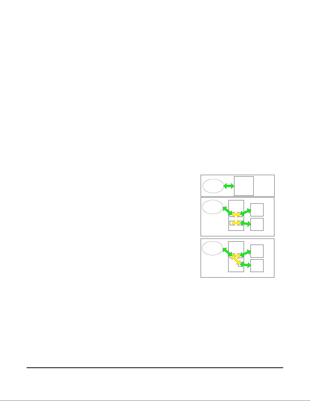
to a single OutBack device, or to multiple devices using an OutBack HUB.
device directly connected to the Mate can be controlled.
STACK board. This is a low cost stacking board that allows the
FX’s to communicate with each other as is required for stacking.
The STACK board also has jacks to connect each device to a Mate.
The Mate can only communicate with the device that is plugged
into a corresponding jack. By manually plugging and unplugging
the Mate, all the devices can be setup and programmed. Plugging
the Mate into the master inverter, allows the Mate to control the
entire system via the master FX. In figure 1B FX1 would be
programmed as the master, and FX 2 as the slave. To control the
system as a whole the Mate would be normally left connected to
FX 1. In this configuration the Mate would only report the status of
FX 1, it does not have any ‘knowledge’ of FX 2. FX 1
communicates with FX 2 directly as a stacked pair, so when the
Mate tells FX 1 to turn on/off or change modes, FX 2 will follow
suit. At this time OutBack offers a STACK2 and a STACK4, for 2
and 4 FX units respectively.
communicate with up to 10 products simultaneously. All products connected to the HUB can report back
status to the Mate, but PC control of all the products is still via the master.
The Mate controller is designed to report status and control the operating modes of OutBack
Figure 1A shows the Mate directly connected to an OutBack FX or MX, obviously only the
Figure 1B shows the Mate connected to an OutBack
A
MATE FX or MX
MATE
B
MATE
C
STACK2
or
STACK4
HUB4or
HUB10
FX 1
FX 2
FX 1
FX 2
Figure 1
Figure 1C shows a Mate connected to an OutBack HUB. The HUB allows the Mate to
Mate Serial Communication Guide Copyright 2007 © OutBack Power Systems, Inc.
19009 62nd Ave NE, Arlington WA 98223 USA
Page 4 of 20 Rev 4.04 10/21/08 Tel 360 435 6030 Fax 360 435 6019
Page 5
Hardware
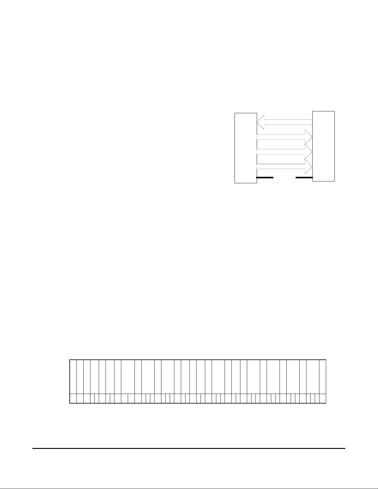
In addition to a LCD and buttons for display and control, an OutBack Mate provides an isolated
RS232 port for PC communication in the form of a female DB9 connector, running at a baud rate of
19200, 8 bits, no parity, 1 stop bit. The Mates’ serial port is optically isolated from the rest of the
OutBack products it is connected too. This isolation requires
that the Mate ‘steals’ power from the PC in order to
RX pin 2 of a DB 9
communicate. Figure 2 shows which lines of a standard PCs’
serial port are used. All pin numbers and names are referenced
from the PC.
The Mate requires that the DTR (pin 4) be driven high
(set) and that RTS (pin 7) be driven low (cleared), in order to
power the port. The Mate transmits data on the RX (pin 2) line,
and listens for commands on the TX (pin 3) line. GND (pin 5)
is ground. No other pins are used by the Mate.
PC Serial
Port
Figure 2
TX pin 3 of a DB 9
DTR pin 4 of a DB 9
RTS pin 7 of a DB 9
GND
Pin 5 of a DB9
Mate Serial
Port
The Mate uses the same USART to communicate with
Outback products that it does to talk to the PC. This requires that all PC to Mate comms must be
initiated by the Mate. Once a second the Mate will transmit a string of ASCII formatted data to the PC.
Simultaneously the Mate will listen for PC sent commands.
Communication Protocol
information dumped from devices connected to the Mate. This scheme will also allow for simple
commands to be passed from the PC to an OutBack product via the Mate. I’ll use the term status page to
indicate the data from a single device. The status pages sent from an FX have a different content then
those from an MX/FM, however the format is the same. I’ll start with describing the FX Status page.
FX Status Page
The status page the Mate emits for each FX connected is 49 Bytes long. Referring to the Figure 3
the byte definitions are as follows:
The only communication protocol supported at this time is an ASCII formatted status
separator
separator
Inverter current
Inverter Address
Start of Status Page
ASCII code
10 X 44 X X 44 X X 44 X X 44 X X X 44 X X X 44 X X 44 X X 44 X X X 44 X X 44 X X X 44 X X X 44 X X X 44 X X X 13
Byte 1 2 3 4 5 6 7 8 9 10 11 12 13 14 15 16 17 18 19 20 21 22 23 24 25 26 27 28 29 30 31 32 33 34 35 36 37 38 39 40 41 42 43 44 45 46 47 48 49
separator
Charger current
separator
Buy current
AC input voltage
separator
AC output voltage
separator
separator
Sell current
separator
FX operational mode
AC mode
separator
Error modes
separator
Battery voltage
Misc
separator
separator
Warning modes
Chksum
separator
end of status page
Figure 3
Mate Serial Communication Guide Copyright 2007 © OutBack Power Systems, Inc.
19009 62nd Ave NE, Arlington WA 98223 USA
Page 5 of 20 Rev 4.04 10/21/08 Tel 360 435 6030 Fax 360 435 6019
Page 6

BYTE
1. ASCII (10) New Line character denoting the start of the status page.
2. This is the Inverter address.
3. ASCII (44) a comma as a data separator.
4. Tens digit of Inverter current.
5. Ones digit of Inverter current.
6. ASCII (44) a comma as a data separator.
7. Tens digit of Charger current..
8. Ones digit of Charger current.
9. ASCII (44) a comma as a data separator.
10. Tens digit of Buy current..
11. Ones digit of Buy current.
12. ASCII (44) a comma as a data separator.
13. Hundreds digit of the AC input voltage.
14. Tens digit of AC input voltage.
15. Ones digit of AC input voltage.
16. ASCII (44) a comma as a data separator.
17. Hundreds digit of the AC output voltage.
18. Tens digit of AC output voltage.
19. Ones digit of AC output voltage.
20. ASCII (44) a comma as a data separator.
21. Tens digit of Sell current.
22. Ones digit of Sell current.
23. ASCII (44) a comma as a data separator.
24. Tens digit of FX operating mode.
25. Ones digit of FX operating mode.
26. ASCII (44) a comma as a data separator.
27. High byte of FX Error mode.
28. Middle byte of FX Error mode.
29. Low byte of FX Error mode.
30. ASCII (44) a comma as a data separator.
31. High byte of FX AC mode.
32. Low byte of FX AC mode
ASCII (44) a comma as a data separator.
33.
34. Tens digit of FX battery voltage.
35. Ones digit of FX battery voltage.
36. Tenths digit of FX battery voltage.
37. ASCII (44) a comma as a data separator.
38. High byte of FX Misc.
39. Middle byte of FX Misc.
40. Low byte of FX Misc.
41. ASCII (44) a comma as a data separator.
42. High byte of FX Warning mode.
43. Middle byte of FX Warning mode.
Mate Serial Communication Guide Copyright 2007 © OutBack Power Systems, Inc.
19009 62nd Ave NE, Arlington WA 98223 USA
Page 6 of 20 Rev 4.04 10/21/08 Tel 360 435 6030 Fax 360 435 6019
Page 7

44. Low byte of FX Warning mode.
45. ASCII (44) a comma as a data separator.
46. Hundreds digit of Chksum.
47. Tens digit of Chksum.
48. Ones digit of Chksum.
49. ASCII (13) carriage return. Denotes end of status page.
Inverter Address: For a directly connected FX this will be a ‘0’ (ASCII (48)). If a HUB is used, the
address will correspond to the port the FX is plugged into. ASCII (49) – ASCII (58) for Ports 1-10.
Inverter current: ‘00’ to ‘99’. This is AC current the FX is delivering to loads in one amp increments.
Charger current: ‘00’ to ‘99’. This is AC current the FX is taking from the AC input and delivering to
the batteries in one amp increments.
Buy current: ‘00’ to ‘99’. This is AC current the FX is taking from the AC input and delivering to the
batteries and pass thru loads in one amp increments
AC input voltage: ‘000’ to ‘256’ The voltage seen at the FXs AC input terminals in one volt increments.
If Misc byte bit 1 set, then this number must be multiplied by 2. See Misc. byte definition below.
AC output voltage: ‘000’ to ‘256’ The voltage on the FXs output AC terminals in one volt increments. If
Misc byte bit 1 set, then this number must be multiplied by 2. See Misc. byte definition below.
Sell current: ‘00’ to ‘99’ This is the AC current the FX is delivering from the batteries to the AC input in
one amp increments
FX operational mode: ‘00’ to ‘99’. Currently reported modes are shown in
figure 4.
Inverter off, search, and on are self explanatory.
Charge refers to a bulk – absorption cycle.
Silent and float correspond to user programmed end of charge behavior.
EQ is a user initiated charge state.
Charger Off means that the user has manually turned the charger off.
NOTE:
(Older Mates reported Errors using a “07”, this is an incompatibility
between older Mates (pre rev 3.30 and newer). Pre 3.30 Mates did not
DATA MODE
"00" Inv Off
"01" Search
"02" Inv On
"03" Charge
"04" Silent
"05" Float
"06" EQ
"07" Charger Off
"08" Support
“09” Sell Enabled
“10” Pass Thru
“90” FX Error
“91” AGS Error
“92” Com Error
Figure 4
actually report any FX mode of greater then “08” even though they were
defined.
Mate Serial Communication Guide Copyright 2007 © OutBack Power Systems, Inc.
19009 62nd Ave NE, Arlington WA 98223 USA
Page 7 of 20 Rev 4.04 10/21/08 Tel 360 435 6030 Fax 360 435 6019
Page 8

Support means that the FX is drawing power from the batteries to support the AC source it is connected
to. Grid-Tie inverters will display support whenever power being removed from the batteries does not
exceed the AC loads of the system. An example would be:
A Grid-Tie FX has a SellRE setting of 25.6VDC and 600W of AC load on its output. DC sources are
contributing 300W to the battery. The GTFX will hold the battery @ 25.6VDC by converting the excess
300W of DC power to AC. The FX Mode would display Support with the Inverter Current meter
showing 300W of production, the Buy Current would show 300W of buying current, for 600W of total
AC Load current. If the AC load is removed the GTFX would have an FX mode of Sell Enabled, and
show 300W of Sell Current.
Support mode is also used to indicate battery power being used to Support a generator when the FX is in
Gen Support mode.
Sell Enabled means that the FX is exporting more power then it has AC loads. This excess power is
flowing out the FXs AC input. Its quantity is measured with the Sell Current meter.
Pass Thru means that the FXs converter is off. The FX is only passing thru the AC from its AC input.
This mode is the result of the FX waiting for some sell criteria (like the five minute timer, or battery
voltage to be > then the SellRE setpoint) before it starts selling.
FX Error means that the FX has shut down for the reason shown in the Error Bytes.
AGS Error means that the Mate has either tried to automatically start the generator in Advanced Gen
Start mode and failed, or that the generator started then stopped unexpectedly.
Comm Error means that the Mate has lost communications with one or more of the OutBack devices
connected to it.
Error modes: ‘000’ to ‘255’ This is an ASCII expression of an 8
bit byte, with each bit representing a different error. Referring to
Figure 5, a returned ‘132’ would be an overtemp and back feed
error. Errors will shut down the FX they occur on, if a master in a
stacked system errors, it will shut the whole system down.
BIT # Value ERROR
1 1 Low VAC output
2 2 Stacking Error
3 4 Over Temp.
4 8 Low Battery
5 16 Phase Loss
6 32 High Battery
7 64 Shorted output
8 128 Back feed
Figure 5
Mate Serial Communication Guide Copyright 2007 © OutBack Power Systems, Inc.
19009 62nd Ave NE, Arlington WA 98223 USA
Page 8 of 20 Rev 4.04 10/21/08 Tel 360 435 6030 Fax 360 435 6019
Page 9

AC mode: ’00’ to ‘99’ This data represents the status of the AC input. No AC is
pretty straight forward, AC Drop means that AC is present but, it is not yet
within valid parameters or the FX has been told not to use it (Drop). AC Use
means AC is present and valid, and the FX will utilize it.
DATA MODE
"00" No AC
"01" AC Drop
"02" AC Use
Figure 6
Battery Voltage: ‘000’ to ‘999’ A 24.8 Vdc battery voltage will be sent as ‘248’. The Resolution of
battery voltage is .1V for 12V systems, .2 for 24V systems, and .4 for 48V systems.
Misc. Byte: ‘000’ to ‘255’ This is an ASCII expression of an 8 bit byte, with each bit representing a
different condition. Only 2 of the bits are used at this time.
Bit 1 indicates a FX with greater than 200 V ac output. If
this bit is set, then AC input and output voltages must be
multiplied by 2 and all currents must be divided by 2.Bit 8
indicates the status of the FX AUX output. A bit value of 1
in the 8th bit means the Aux output is active.
BIT # Value
1 1230V unit
2 2Reserved/used by FX
3 4Reserved/used by FX
4 8Reserved/used by FX
5 16Reserved/used by FX
6 32Reserved/used by FX
7 64Reserved/used by FX
8 128AUX output ON
Figure 7
Mate Serial Communication Guide Copyright 2007 © OutBack Power Systems, Inc.
19009 62nd Ave NE, Arlington WA 98223 USA
Page 9 of 20 Rev 4.04 10/21/08 Tel 360 435 6030 Fax 360 435 6019
Page 10

Warning modes: ‘000’ to ‘255’ This is an ASCII expression of
an 8 bit byte, with each bit representing a different error.
Referring to Figure 8, a returned ‘010’ would be AC input low
voltage and freq. FXs with warnings will continue to operate.
See figure 8.
BIT # Value Warning
1 1 AC Input Freq High
2 2 AC Input Freq Low
3 4 Input VAC High
4 8 Input VAC Low
5 16 Buy Amps > Input size
6 32 Temp sensor failed
7 64 Comm Error
8 128 Fan Failure
Figure 8
Chksum: ‘000’ to ‘999’. This is a simple additive chksum of the decimal values of the Status page.
Example:
0,00,00,00,119,000,00,00,000,01,254,008,000,031
0+0+0+0+0+0+0+1+1+9+0+0+0+0+0+0+0+0+0+0+0+1+2+5+4+0+0+8+0+0+0=031
0,00,00,00,120,000,00,02,000,01,254,008,000,025
0+0+0+0+0+0+0+1+2+0+0+0+0+0+0+0+2+0+0+0+0+1+2+5+4+0+0+8+0+0+0=025
Mate Serial Communication Guide Copyright 2007 © OutBack Power Systems, Inc.
19009 62nd Ave NE, Arlington WA 98223 USA
Page 10 of 20 Rev 4.04 1 0/21/08 Tel 360 435 6030 Fax 360 435 6019
Page 11

MX/FM Status Page
The status page the Mate emits for each MX connected is 49 Bytes long. Referring to the Figure 9 the
byte definitions are as follows:
Start of Status Page
10 X 44 48 48 44 X X 44 X X 44 X X X 44 X X X 44 48 X 44 X X 44 X X X 44 X X 44 X X X 44 X X X X 44 48 48 44 X X X 13
ASCII code
Byte 1 2 3 4 5 6 7 8 9 10 11 12 13 14 15 16 17 18 19 20 21 22 23 24 25 26 27 28 29 30 31 32 33 34 35 36 37 38 39 40 41 42 43 44 45 46 47 48 49
Unused
Separator
Separator
Separator
Separator
MX Address
PV current
Charger current
Separator
PV voltage
Daily KWH
unused
Separator
Separator
Separator
Aux mode
Charger Current tenths
Separator
Error modes
Separator
Battery voltage
MX Charger mode
Daily AH
Separator
Separator
Chksum
Separator
end of status page
Figure 9
1. ASCII (10) New Line character denoting the start of the status page.
2. MX/FM address.
3. ASCII (44) a comma as a data separator.
4. Unused, ASCII (48).
5. Unused, ASCII (48).
6. ASCII (44) a comma as a data separator.
7. Tens digit of Charger current.
8. Ones digit of Charger current.
9. ASCII (44) a comma as a data separator.
10. Tens digit of PV current.
11. Ones digit of PV current.
12. ASCII (44) a comma as a data separator.
13. Hundreds digit of the PV input voltage.
14. Tens digit of PV input voltage.
15. Ones digit of PV input voltage.
16. ASCII (44) a comma as a data separator.
17. Tens digit of Daily kWH.
18. Ones digit of Daily kWH.
19. Tenths digit of Daily kWH.
20. ASCII (44) a comma as a data separator.
21. Unused, ASCII (48).
22. Tenths of amp Charger current (FM80 / FM60 only)
23. ASCII (44) a comma as a data separator.
24. High byte of Aux mode.
25. Low byte of Aux mode.
26. ASCII (44) a comma as a data separator.
27. High byte of Error mode.
28. Middle byte of Error mode.
29. Low byte of Error mode.
30. ASCII (44) a comma as a data separator.
High byte of charger mode.
31.
32. Low byte of charger mode.
33. ASCII (44) a comma as a data separator.
Mate Serial Communication Guide Copyright 2007 © OutBack Power Systems, Inc.
19009 62nd Ave NE, Arlington WA 98223 USA
Page 11 of 20 Rev 4.04 1 0/21/08 Tel 360 435 6030 Fax 360 435 6019
Page 12

34. Tens digit of battery voltage.
35. Ones digit of battery voltage.
36. Tenths digit of battery voltage.
37. ASCII (44) a comma as a data separator.
38. Thousands digit of daily AH.
39. Hundreds digit of daily AH.
40. Tens digit of daily AH.
41. Ones digit of daily AH.
42. ASCII (44) a comma as a data separator.
43. Unused, ASCII (48).
44. Unused, ASCII (48).
45. ASCII (44) a comma as a data separator.
46. Hundredths digit of Chksum.
47. Tens digit of Chksum.
48. Ones digit of Chksum.
49. ASCII (13) carriage return. Denotes end of status page.
MX/FM Address: For directly connected MX/FM this will be an ‘A’ ASCII (65). If a HUB is used, the
address will correspond to the port the MX/FM is plugged into. ASCII (66) – ASCII (75) for Ports 1-10.
Charger current: ‘00’ to ‘99’ This is DC current the MX/FM is delivering to the batteries in one amp
increments.
PV current: ‘00’ to ‘99’ This is DC current the MX/FM is taking from the PV panels in one amp
increments
PV panel voltage: ‘000’ to ‘255’ The voltage seen at the MX/FM PV input terminals in one volt
increments.
*Daily KWH: ‘000’ to ‘999’ Running total of KWatt Hours produced by the PV array. Formatted as
XX.X (999 = 99.9 KWH). This number is reset every morning when the MX/FM wakes up, or every 24
hours in locations with no nightfall.
Charger current tenths of Amp: 0 to 9 (FlexMAX 80 and FlexMAX 60 only)
Add Charger current plus tenths to equal charger current displayed on FM80 or FM60
Mate Serial Communication Guide Copyright 2007 © OutBack Power Systems, Inc.
19009 62nd Ave NE, Arlington WA 98223 USA
Page 12 of 20 Rev 4.04 1 0/21/08 Tel 360 435 6030 Fax 360 435 6019
Page 13

MX60 Aux mode: ‘00’ to ‘99’ This shows what Aux output mode is being
run on the MX. Refer to MX manual for mode descriptions. FLEXmax 80
or FLEXmax 60 the lower 6 bits represent the programmed Aux mode. If
bit 7 is set (data greater than 63) then Aux mode is active.
DATA MODE
"00" Disabled
"01" Diversion
"02" Remote
"03" Manual
"04" Vent Fan
"05" PV Trigger
“06”* Float
“07”* ERROR Output
“08”* Night Light
“09”* PWM Diversion
“10”* Low Battery
*FM80/FM60
Figure 10
Error modes: MX60 Error modes are implemented for MX versions greater than 5.11 and FLEXmax 80
and FlexMAX 60.
Error modes: ‘000’ to ‘255’ This is an ASCII expression of an 8 bit byte, with each bit representing a
different error. Referring to Figure 11, a returned ‘032’ would be shorted battery sensor.
BIT # Value Warning
1 1 unused
2 2 unused
3 4 unused
4 8 unused
5 16 unused
6 32 Shorted Battery Sensor
7 64 Too Hot
8 128 High VOC
Figure 11
MX/FM Charge mode: ’00’ to ‘99’ This data represents the MXs charger mode.
See Figure 12.
DATA MODE
"00" Silent
"01" Float
"02" Bulk
"03" Absorb
“04” EQ
Figure 12
Battery Voltage: ‘000’ to ‘999’, A 24.8 Vdc battery voltage will be sent as ‘248’.
*Daily AH: ‘0000’ to ‘2000’, (FLEXmax 80 and FLEXmax 60 only) Running daily total of amp hours
produced by the charge controller. ‘9999’ is returned if charge controller is MX60
*On FLEXmax 80 and FLEXmax 60 this number is reset at midnight if connected to MATE.
Mate Serial Communication Guide Copyright 2007 © OutBack Power Systems, Inc.
19009 62nd Ave NE, Arlington WA 98223 USA
Page 13 of 20 Rev 4.04 1 0/21/08 Tel 360 435 6030 Fax 360 435 6019
Page 14

Chksum: ‘000’ to ‘999’ this is a simple additive chksum of the decimal values of the Status page.
NOTE: Since the MX address is an alpha character, it’s checksum needs to be calculated
differently then the FX’s numerical address. Addresses reported for the MX/FM will be ‘A” (ASCII 66)
through ‘K” (ASCII 75) corresponding to ports 1-10. The value to use for Chksum calculations should
be the received ASCII value – 48 (For the received character ‘A” the chksum value to be used would be
65-48, or 17.
Example:
A,00,08,06,034,031,00,05,000,02,262,000,000,059
17+0+0+0+8+0+6+0+3+4+0+3+1+0+0+0+5+0+0+0+0+2+2+6+2+0+0+0+0+0+0=059
D,00,07,05,034,031,04,05,000,02,262,000,000,064
20+0+0+0+7+0+5+0+3+4+0+3+1+0+4+0+5+0+0+0+0+2+2+6+2+0+0+0+0+0+0=064
Mate Serial Communication Guide Copyright 2007 © OutBack Power Systems, Inc.
19009 62nd Ave NE, Arlington WA 98223 USA
Page 14 of 20 Rev 4.04 1 0/21/08 Tel 360 435 6030 Fax 360 435 6019
Page 15

FLEXnet DC Status Page
The status page the MATE emits for the FLEXnet DC is 49 bytes long. Referring to the Figure 13 the
byte definitions are as follows:
ASCII code 10 X 44 X X X X 44 X X X X 44 X X X X 44 X X 44 X X X X X 44 X X X 44 X X X 44 X X X 44 X X 44 X X 44 X X X 13
Byte
Figure 13
BYTE
separator
Start of status page
FNDC Address
1 2 3 4 5 6 7 8 9 10 11 12 13 14 15 16 17 18 19 20 21 22 23 24 25 26 27 28 29 30 31 32 33 34 35 36 37 38 39 40 41 42 43 44 45 46 47 48 49
separator
Shunt A Amps
separator
Shunt B Amps
separator
Shunt C Amps
separator
Extra data identifier
separator
Extra data
separator
Battery voltage
separator
State of charge
separator
separator
Status flags
Shunt 1 enable
Shunt 2 enable
Shunt 3 enable
Battery Temperature
1. ASCII (10) New Line character denoting the start of the status page.
2. FLEXnet DC address.
3. ASCII (44) a comma as a data separator.
4. Hundreds digit of shunt ‘A’ current.
5. Tens digit of shunt ‘A’ current.
6. Ones digit of shunt ‘A’ current.
7. Tenths digit of shunt ‘A’ current.
8. ASCII (44) a comma as a data separator.
9. Hundreds digit of shunt ‘B’ current.
10. Tens digit of shunt ‘B’ current.
11. Ones digit of shunt ‘B’ current.
12. Tenths digit of shunt ‘B’ current.
13. ASCII (44) a comma as a data separator.
14. Hundreds digit of shunt ‘C’ current.
15. Tens digit of shunt ‘C’ current.
16. Ones digit of shunt ‘C’ current.
17. Tenths digit of shunt ‘C’ current.
18. ASCII (44) a comma as a data separator.
19. Tens digit of extra data identifier.
20. Ones digit of extra data identifier.
21. ASCII (44) a comma as a data separator.
22. Ten thousands digit of extra data.
23. Thousands digit of extra data.
24. Hundreds digit of extra data.
25. Tens digit of extra data.
26. Ones digit of extra data.
27. ASCII (44) a comma as a data separator.
28. Tens digit of FLEXnet DC battery voltage.
29. Ones digit of FLEXnet DC battery voltage.
30. Tenths digit of FLEXnet DC battery voltage.
31. ASCII (44) a comma as a data separator.
Chksum
separator
end of status page
Mate Serial Communication Guide Copyright 2007 © OutBack Power Systems, Inc.
19009 62nd Ave NE, Arlington WA 98223 USA
Page 15 of 20 Rev 4.04 1 0/21/08 Tel 360 435 6030 Fax 360 435 6019
Page 16

32. Hundreds digit of state of charge.
33. Tens digit of state of charge.
34. Ones digit of state of charge.
35. ASCII (44) a comma as a data separator.
36. Shunt A enabled flag.
37. Shunt B enabled flag.
38. Shunt C enabled flag.
39. ASCII (44) a comma as a data separator.
40. High byte of status flags.
41. Low byte of status flags.
42. ASCII (44) a comma as a data separator.
43. Tens digit of battery temperature.
44. Ones digit of battery temperature.
45. ASCII(44) a comma as a data separator.
46. Hundreds digit of Chksum.
47. Tens digit of Chksum.
48. Ones digit of Chksum.
49. ASCII (13) carriage return. Denotes end of status page.
FLEXnet DC Address: The address will correspond to the HUB port the FLEXnet DC is plugged into.
Ascii(97) – Ascii(106) for Ports 1-10.
Shunt ‘A’ current ‘0000’ to ‘9999’ amps, in tenth amp increments.
Shunt ‘B’ current ‘0000’ to ‘9999’ amps, in tenth amp increments.
Shunt ‘C’ current ‘0000’ to ‘9999’ amps, in tenth amp increments.
Mate Serial Communication Guide Copyright 2007 © OutBack Power Systems, Inc.
19009 62nd Ave NE, Arlington WA 98223 USA
Page 16 of 20 Rev 4.04 1 0/21/08 Tel 360 435 6030 Fax 360 435 6019
Page 17

Extra data identifier: ‘00’ to ‘99’, this is an ASCII expression of a 8 bit byte with bits 1 through 7 being
used.
Bit: 7 extra data numeric sign
0: positive value
1: negative value
Bits: 1-6
0: Accumulated AH shunt ‘A’
1: Accumulated kWH shunt ‘A’
2: Accumulated AH shunt ‘B’
3: Accumulated kWH shunt ‘B’
4: Accumulated AH shunt ‘C’
5: Accumulated kWH shunt ‘C’
6: Days since full
7: Today’s minimum SOC
8: Today’s net input AH
9: Today’s net output AH
10. Today’s net input kWH
11: Today’s net output KWH
12: *Charge factor corrected Net battery AH
13: *Charge factor corrected Net battery kWH
14-35 Reserved
kWH values: ‘00000’ to ‘65535’, 000.00 to 655.35 Kwatts
AH values: ‘00000’ to ‘65535’, 0 to 65535
Days since full output: ‘00000’ to ‘09999’, 0.0 to 999.9
Minimum SOC output: ‘00000’ to ‘00100’, 0 to 100 percent
*MATE version 4.04 and above
FLEXnet DC battery voltage: ‘000’ to ‘999’, A 24.8 Vdc battery voltage will be sent as ‘248’.
Battery State of charge: ‘000’ to ‘100’, 0 to 100 percent.
Mate Serial Communication Guide Copyright 2007 © OutBack Power Systems, Inc.
19009 62nd Ave NE, Arlington WA 98223 USA
Page 17 of 20 Rev 4.04 1 0/21/08 Tel 360 435 6030 Fax 360 435 6019
Page 18

Shunt enable flags: ‘0’ enabled, ‘1’ disabled.
Status Flags: ‘00’ to ‘63’ This is an ASCII expression of an 8 bit byte, with each bit representing a
different flag. Relay state is 1 when relay is closed, 0 if relay is open. Relay mode is 0 if manual mode, 1
if relay control is in automatic mode. Referring to Figure 14, a returned ‘009’ would be charge parms
met and shunt 1 values are negative.
BIT # Value Warning
1 1 Charge parms met
2 2 Relay mode:
3 4 Relay state:
4 8 Shunt A values are negative
5 16 Shunt B values are negative
6 32 Shunt C values are negative
Figure 14
Battery temperature 00 to 70 and 99
99 = out of range or no RTS installed
Battery temperature C = reported battery temperature – 10, Range -10C to 60C
Chksum: ‘000’ to ‘999’ This is a simple additive chksum of the decimal values of the Status page.
NOTE: Since the FLEXnet DC address is an alpha character, its checksum needs to be
calculated differently then the FX’s numerical address. Addresses reported for the FLEXnet DC will be
‘a’ (ASCII 97) through ‘j’ (ASCII 106) corresponding to ports 1-10. The value to use for Chksum
calculations should be the received ASCII value – 48 (For the received character ‘a” the chksum value
to be used would be 97-48, or 49.
Example:
c,0000,0126,0000,02,00023,287,099,001,00,33,109
51+0+0+0+0+0+1+2+6+0+0+0+0+0+2+0+0+0+2+3+2+8+7+0+9+9+0+0+1+0+0+3+3=109
c,0583,0596,0000,05,00000,266,099,001,08,35,141
51+0+5+8+3+0+5+9+6+0+0+0+0+0+5+0+0+0+0+0+2+6+6+0+9+9+0+0+1+0+8+3+5=141
Mate Serial Communication Guide Copyright 2007 © OutBack Power Systems, Inc.
19009 62nd Ave NE, Arlington WA 98223 USA
Page 18 of 20 Rev 4.04 1 0/21/08 Tel 360 435 6030 Fax 360 435 6019
Page 19

Commands
The Mate will accept the following commands for controlling FXs only. The Mate only passes
these commands to the master inverter in a HUB stacked system. The master will change the modes of
all slaved inverters to suit. ON, SEARCH, OFF, USE, DROP, AUX ON, and AUX OFF. ON will turn
the FX to ON mode, if no AC input is being used the inverter will provide a constant output. SEARCH
will place the FX in Search mode, allowing for a pulsed AC output when load levels drop below the
programmed limits for that FX. OFF will not allow the FX to invert. It will still charge and pass through
AC depending on the AC mode. These commands will only be passed onto the master inverter in a HUB
based system. USE will allow the AC input to be used if it meets the programmed limits of the FX.
DROP will not allow AC input to be utilized, unless there is an error. Errors will cause the FX to change
the AC mode to USE. AUX ON energizes the 12V Aux output of the FX, AUX OFF de-energizes it.
AUX control is only available for master inverters on a HUB. For more information on FX operational
modes, download the FX manual at http://www.outbackpower.com/manuals.htm
Commands are sent as ASCII
characters, the same character is sent twice for
error checking. Figure 14 shows a chart of
utilized commands.
Command Timing
DATA ASCII COMMAND
"OO" ASCII(79) ASCII(79) ON
"SS" ASCII(83) ASCII(83) SEARCH
"FF" ASCII(70) ASCII(70) OFF
"UU" ASCII(85) ASCII(85) USE
"DD" ASCII(68) ASCII(68) DROP
"ZZ" ASCII(90) ASCII(90) AUX ON
"XX" ASCII(88) ASCII(88) AUX OFF
Figure 14
The Mate will
send a Status Page for
each FX it is connected
to, either directly or via
a HUB. A Mate
directly connected to a
FX will send out a
single Status Page per
second, if a HUB is
used, Status Pages for
all FXs will be
transmitted once a
second. The Mate
listens for commands
starting with the first
byte it transmits, it will
continue to listen for
~200 to 250 mS after
transmission starts (See
Figure 15
Figure 15).
.
Mate Serial Communication Guide Copyright 2007 © OutBack Power Systems, Inc.
19009 62nd Ave NE, Arlington WA 98223 USA
Page 19 of 20 Rev 4.04 1 0/21/08 Tel 360 435 6030 Fax 360 435 6019
Page 20

If a 2 byte command is received during this ‘Listen Time’, the Mate will cease listening to the PC and
process the received command (See figure 16).
An invalid
command will be ignored
by the Mate. The result of
any valid command will
be shown in the next
seconds’ Status Page.
At this time
commands will only be
sent to the master FX on
any STACK or HUB
stacked system. The slaves
will follow all operational
mode changes of the FX
except AUX ON and
AUX OFF. Only the
masters AUX output can
be controlled at this time.
Figure 16
It is also important to note that a users pressing any of the Mate buttons interrupts both Status
page transmissions and listen time for 2 seconds. A button press will cease all PC communications until
no button has been pressed for 2 seconds.
More Information
Information on FX setup, programming, and operational modes can be found on the OutBack
web site http://www.outbackpower.com/manuals.htm
matedev@outbackpower.com .
. Questions and comments can be directed to
Mate Serial Communication Guide Copyright 2007 © OutBack Power Systems, Inc.
19009 62nd Ave NE, Arlington WA 98223 USA
Page 20 of 20 Rev 4.04 1 0/21/08 Tel 360 435 6030 Fax 360 435 6019
 Loading...