

Page 1
Integrated Battery Rack
Purpose
This document provides instructions for initial assembly and
installation of the OutBack Integrated Battery Rack (IBR).
Scope
Installation Instructions
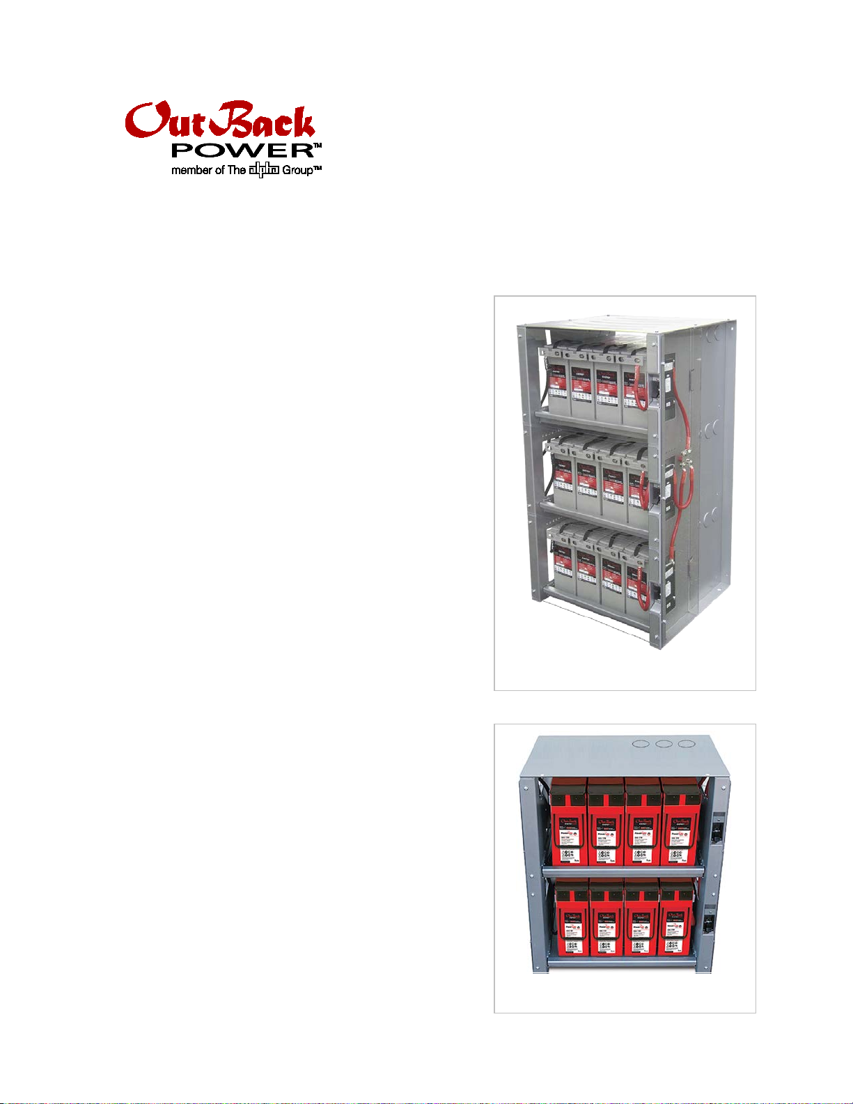
This document applies to
the three-shelf IBR-3-48-175, depicts OutBack EnergyCell RE
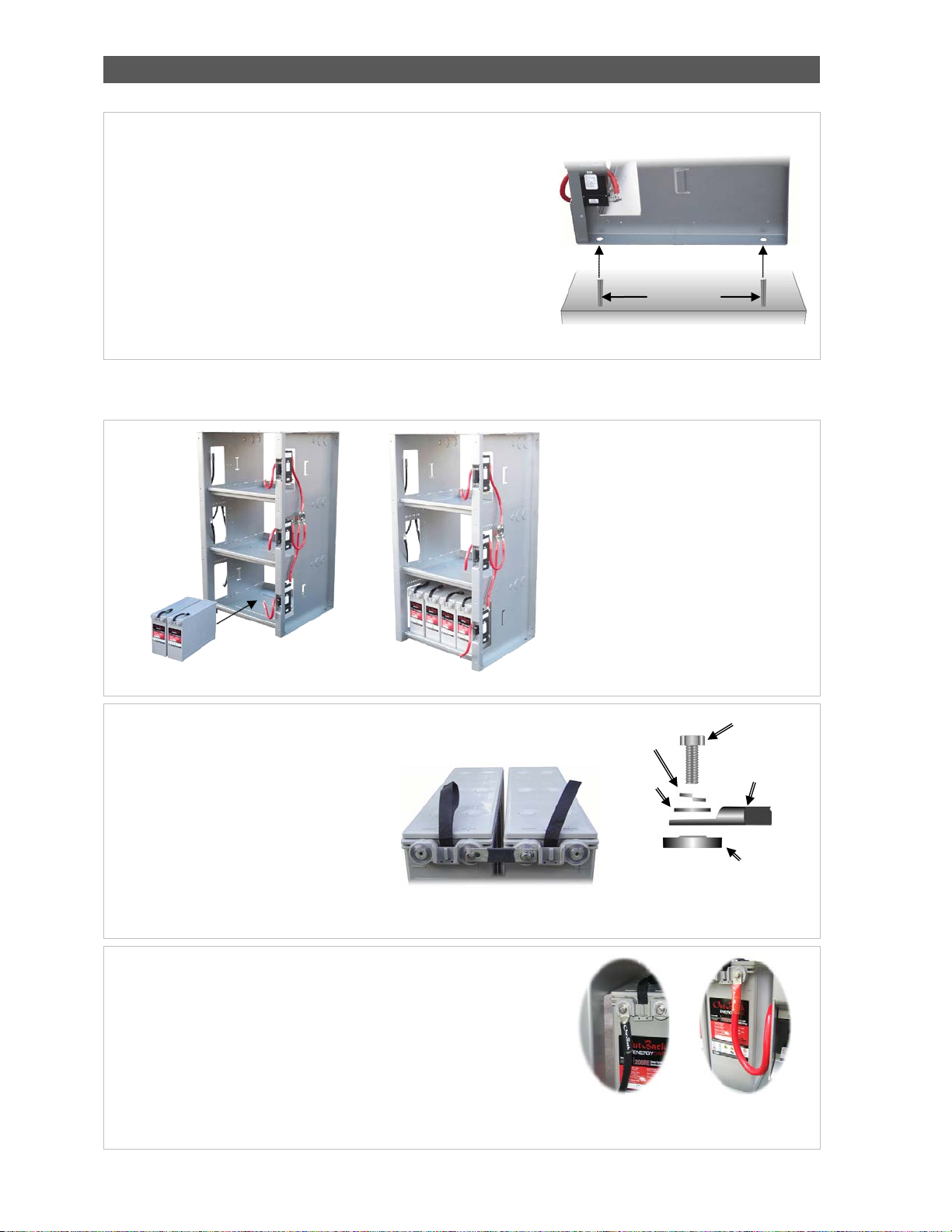
batteries. Figure 2, the two-shelf IBR-2-48-175, depicts
OutBack EnergyCell GH batteries. If other batteries are
used, they must be 12 Vdc batteries which also meet the
following requirements:
AGM valve-regulated lead-acid recombinant type
Maximum discharge 100 cc/hr per battery
Maximum discharging temperature 160°F (60°C)
all models
of the IBR. Figure 1,
Parts Included
Rack assembly
Front protective shields
Side protective shields
Hardware for protective shields
EnergyCell Battery Manual
IBR Installation Instructions (this document)
Figure 1 IBR-3-48-175
Assembly
: If installed in the United States, all wiring methods
NOTE
shall be in accordance with the National Electrical Code
(NFPA 70), Current Edition. If installed in Canada, all wiring
methods shall be in accordance with the Canadian Electrical
Code, C22.1, Current Edition.
Figure 2 IBR-2-48-175
900-0130-01-00 Rev C 1
Page 2
EnergyCell RE Battery Rack Instructions
5. Attach the interconnect bars to place the
manual or instructions.
Flat
Washer
Lock
Battery Cable
Hex Bolt
Mounting Surface
Negative Cable
Positive Cable
To assemble the integrated battery rack:
1.
2.
IMPORTANT
19” (48.3 cm)
Front
Back
NOTE: Slots are present under the
6. The rack is equipped with cables for each shelf (positive on the right,
ring. The cables lead to separate buses on each side of
Install four ½” studs into the mounting surface (concrete or a
similarly reinforced material). From the front to the back, the stud
centers should be spaced 19” (48.3 cm) apart, as shown in
Spacing from left to right should be 25” (63.5 cm) apart.
Lower the battery rack over the four studs as shown in Figure 3 and
settle the rack in place.
Alternately, ½” bolts can be inserted through the mounting holes
into prepared openings.
: The battery rack must be mounted on a level surface.
Figure 3.
Figure 3 Mounting on Floor Studs
3. Secure the studs or bolts with nuts or appropriate hardware. Anchor the rack according to local building codes.
4. Load the batteries into the rack. Load the bottom shelf first to prevent balancing issues. Proceed to the next shelf.
front edge of each shelf for strapping
the batteries down if necessary.
batteries in series. Batteries should be
connected in series as appropriate to
meet the system voltage requirements.
Follow all instructions in the battery
manual and use the recommended
torque values. Install hardware in the
order shown in
hardware in a different order than
shown unless specified by the battery
Figure 5. Do not install
Figure 5 Battery Interconnect Bars and Hardware
negative on the left). Connect each cable to the appropriate side of
Figure 4 Inserting Batteries
each battery st
the rack that place each string in parallel. (See Figure 7.)
Each positive (red) cable is connected to a 175-amp circuit breaker
which protects the batteries on that shelf.
Figure 6 Battery Connections
2 900-0130-01-00 Rev C
Washer
Lug
Page 3

EnergyCell RE Battery Rack Instructions
10. Install the protective shields on the left and right sides of the battery
rack. Each shield has an edge which is designed to slide into a metal
e rack. (See below.) Once the edge of the shield is secured,
the other side can be attached using M6 screws. (See the illustration
1
Install the protective shields on the front of each battery shelf. Make
Machine
Screw
Machine
Machine
Screw
Circuit
Breaker
Shield
NOTE
battery rack does not require
additional ventilation.
Provide adequate ventilation for the
room where the battery rack is installed
7. Connect a ground cable to the battery rack.
8
fourth cable for battery loads (see
complete the circuit,
9. After load cables have been routed inside the enclosure, they should exit
Load Cable
Cable entering
Conduit
Ground
The positive and negative bus bars are marked with “+” and “-“ symbols respectively.
The ground terminal is marked with the
symbol.
The ground terminal is located directly below
the negative bus bar (see right). Make sure to
follow all applicable electrical codes when
grounding the rack.
. The positive and negative bus bars have multiple
attachment points. The battery cables inside the
rack are already attached (see left). The user
should attach a
right). This load cable should be sized
appropriately. As shown to the right, the load
cable must be routed inside the enclosure using
one of the side openings. To
the return load cable should connect to the bus
bar on the other side of the rack and also routed
inside the enclosure.
using one of the conduit openings. The IBR-3-48-175 has six 2” conduit
knockouts on each side of the rack. The IBR-2-48-175 has four 2” conduit
knockouts on either side of the rack and three on top.
For users of the GS Load Center: The top knockouts are designed to
align with the GSLC cabling for ease of installation.
Figure 7 Bus and Load Cabling
Terminal
enclosure
tab on th
to the right.)
1.
certain to orient the shield correctly. The shield has an opening to
allow access to the circuit breaker for each set of batteries. (See the
illustration to the right.) If the shield is oriented incorrectly, it will
block access to the circuit breaker.
: The
Figure 8 Protective Shields (sides and front)
900-0130-01-00 Rev C 3
Screw
.
Page 4

Installing Shunts
Address:
Corporate Headquarters
Arlington, WA 98223 USA
European Office
Schwabach, Germany
Telephone:
+1.360.435.6030
+1.360.435.6019 (Fax)
+49.9122.79889.0
Email:
Support@outbackpower.com
Website:
http://www.outbackpower.com
To Install a Shunt or Shunts:
Up to three shunts may be installed for
FLEXnet
1.
2.
3.
4.
Holes
Twin
the use of a battery monitor such as the
DC. Perform the following steps before step 5 on page 2.
Remove the negative bus bar and cables from the left side of the rack (see right).
Unbolt the individual cables from the bus bar.
Three pairs of holes are located in the area where the bus bar is mounted (below,
left). A shunt can be placed over each set of holes. Each shunt has twin screws
(below, center) which can be used for mounting.
Reinstall the negative bus bar so that it mounts across the inner terminal of each
shunt (below, right). Each negative battery cable must not be bolted to the bus bar,
but should connect to the outer terminal of each shunt. However, the load cable
must connect to the negative bus bar.
The battery monitor’s voltage sensing wires must connect to the bus bars (positive
and negative), not the batteries.
Screws
Contact Information
Notice of Copyright
Integrated Battery Rack Installation Manual © August 2013 by OutBack Power Technologies.
All Rights Reserved.
Date and Revision
August 2013, Revision C
Part Number
900-0130-01-00 Rev C
Figure 9 Installing Shunts
17925 – 59th Avenue N.E.
Suite B
+1.360.618.4363 (Technical Support)
Hansastrasse 8
D-91126
+49.9122.79889.21 (Fax)
 Loading...