

Page 1

Manual de programación
de los INVERSORES/
CARGADORES
GTFX Y GVFX SERIE LA
interactivos con la red
Page 2

Sobre OutBack Power Systems
OutBack Power Systems es líder en tecnología de conversión de energía de avanzada. Nuestros
productos incluyen inversores/cargadores de onda sinusoidal pura, controladores de punto de carga
de energía máxima, componentes de comunicación entre sistemas, así como paneles de interruptores,
interruptores, accesorios y sistemas montados.
Información de contacto
Teléfono: (+1) 360.435.6030 (América del Norte) Fax: (+1) 360.435.6019
(+34) 93.654.9568 (Barcelona, España)
Dirección: América del Norte Ocina de Ventas en Europa
19009 62nd Avenue NE C/ Castelló, 17
Arlington, WA USA 08830 - Sant Boi de Llobregat
BARCELONA, España
Correo electrónico: Support@OutbackPower.com
Web: www.OutBackPower.com
Descargo de responsabilidad
A MENOS QUE SE ACUERDE ESPECÍFICAMENTE POR ESCRITO, OUTBACK POWER SYSTEMS:
(a) NO GARANTIZA LA EXACTITUD, LA SUFICIENCIA NI LA IDONEIDAD DE CUALQUIER INFORMACIÓN
TÉCNICA O DE OTRA CLASE PROVISTA EN SUS MANUALES O EN OTRA DOCUMENTACIÓN.
(b) NO SE RESPONSABILIZA POR LAS PÉRDIDAS O DAÑOS, YA SEAN DIRECTOS, INDIRECTOS,
CONSECUENTES O ACCIDENTALES, QUE PUEDAN SURGIR DEL USO DE TAL INFORMACIÓN. EL USO DE
ESTA INFORMACIÓN SERÁ ENTERA RESPONSABILIDAD DEL USUARIO.
Resumen de la garantía
OutBack Power Systems Inc. garantiza que los productos que elabora no presentarán defectos en
los materiales ni en la mano de obra durante un período de dos (2) años, sujeto a las condiciones
establecidas en el detalle de la garantía que está en la contratapa de este manual.
OutBack Power Systems no se hace responsable de las fallas del sistema, los daños o las lesiones
causados por la instalación indebida de sus productos.
Nota sobre la propiedad intelectual
Manual de programación de los inversores/cargadores GTFX y GVFX SERIE LA interactivos con la red
©OutBack Power Systems, marzo de 2009. Todos los derechos reservados.
Marcas comerciales
OutBack Power es una marca comercial registrada de OutBack Power Systems.
Fecha y revisión
Mayo de 2009, revisión A
Page 3

TABLA DE CONTENIDOS
Bienvenido al sistema inversor/cargador GTFX y GVFX SERIE LA de OutBack Power Systems ....................2
Seguridad ............................................................................................................................................................................................. 2
Programación del inversor/cargador
Inquietudes ......................................................................................................................................................................................... 3
Opciones .............................................................................................................................................................................................. 3
Componentes y conexiones ............................................................................................................................................................. 4
Opciones de apilamiento .................................................................................................................................................................... 7
Apilamiento y asignación de estados de FX ........................................................................................................................... 8
Programación de los FX ........................................................................................................................................................................ 9
Maestro y esclavo clásico .........................................................................................................................................................12
Maestro trifásico y esclavo trifásico ....................................................................................................................................13
Niveles de almacenamiento de energía ..................................................................................................................................14
Ajustes de venta ......................................................................................................................................................................................14
Encendido (ON) de CA ........................................................................................................................................................................15
Funciones auxiliares (AUX) ................................................................................................................................................................17
Lista de funciones auxiliares (AUX).....................................................................................................................................20
Funciones ajustables de salida auxiliar (AUX) ..............................................................................................................20
Carga de baterías ....................................................................................................................................................................................23
Mantenimiento ........................................................................................................................................................................................23
Valores predeterminados del FX ...................................................................................................................................................24
Garantía ........................................................................................................................................................................................................26
Registro del producto ..........................................................................................................................................................................28
GTFX y GVFX SERIE LA............................................................................................. 3
1
Page 4

BIENVENIDO AL SISTEMA INVERSOR/CARGADOR GTFX Y GVFX SERIE LA
INTERACTIVOS CON LA RED DE OUTBACK POWER SYSTEMS
Los inversores/cargadores serie GTFX y GVFX (también conocidos como serie FX) ofrecen un completo sistema de
conversión de energía —CC a CA, carga de baterías y conmutador de transferencia de CA— que presta un completo
servicio interactivo con la red. También pueden usarse en aplicaciones autónomas o de respaldo. Estos sistemas están
diseñados para interiores o lugares cerrados.
Los inversores/cargadores GTFX y GVFX SERIE LA generan un voltaje de salida de 127 V CA por inversor. Estos inversores se
han programado para que este voltaje de las fuentes de CA resulte óptimo. En este manual, suele decirse que el voltaje es
de “120 V CA”. No obstante, este valor nominal hace referencia al valor real de 127 V CA.
NOTA: Este producto no conforma con UL 1741 o ETL. No se puede usar en EEUU, Canadá
o Puerto Rico.
OutBack Power Systems hace todo lo posible para garantizar que los componentes adquiridos funcionen de manera
adecuada y segura, siempre que se los instale respetando los códigos eléctricos locales y nacionales. Lea todas las instrucciones siguientes y las instrucciones de cualquier otro componente de OutBack que forme parte del sistema de suministro
de energía.
en el Manual de instalación de los inversores/cargadores GTFX y GVFX SERIE LA interactivos con la red.
Instrucciones para la conexión a tierra: Cada FX debe conectarse a un sistema de cableado permanente con conexión a tierra. Para la mayoría de las instalaciones, el conductor negativo de la batería debe estar enlazado al sistema de
conexión a tierra en un solo punto del sistema de CC. Todas las instalaciones deben cumplir con todos los códigos y
reglamentos locales y nacionales. La conexión a tierra del sistema es responsabilidad del instalador del sistema.
Puede consultar más instrucciones sobre ajustes individuales de los sistemas FX y conjuntos de sistemas
La conexión a tierra del equipo está identicada con este símbolo:
El Manual de programación de los inversores/cargadores GTFX y GVFX SERIE LA interactivos con la red cubre los aspectos
de seguridad y la programación o “apilamiento” de varios FX con el MATE de OutBack Power Systems.
NOTA:
• Se necesita un MATE de OutBack para programar los FX con valores diferentes a los predeterminados.
• Si se usa un controlador de carga de OutBack, asegúrese de leer el manual para que funcione de manera óptima con el FX.
• Al encenderse, el GTFX/GVFX detecta automáticamente la presencia de una red de distribución de energía eléctrica y se
conecta a ella tras una demora de 30 segundos. Se produce una demora adicional de 12 segundos hasta que comienza la
carga de baterías. El inversor puede vender energía a la red una vez que las baterías estén cargadas.
INSTRUCCIONES IMPORTANTES DE SEGURIDAD
Precauciones generales
1. Sea precavido al trabajar con corrientes eléctricas, componentes eléctricos y baterías. El contacto con la electricidad
puede producir al instalador o usuario descargas, quemaduras, lesiones o incluso la muerte.
2. Lea todas las instrucciones y señales de precaución del FX y las baterías, y todas las secciones pertinentes de este
manual y los manuales de otros componentes antes de usar el sistema.
3. Asegúrese de que cada unidad se instale de manera segura, según lo indicado en el Manual de instalación de los
inversores/cargadores GTFX y GVFX SERIE LA interactivos con la red.
4. Cumpla todos los códigos eléctricos locales y nacionales al instalar los equipos y componentes de OutBack.
2
Page 5

PROGRAMACIÓN DEL INVERSOR/CARGADOR SERIE FX INTERACTIVO CON LA RED
NOTA: Consulte el
para instalar, cablear y conectar cada inversor/cargador serie FX. En este manual de programación, se
presupone que todos los FX ya se han instalado y están listos para programar según el cableado. Para
familiarizarse con los conceptos de programación, lea todo el manual antes de programar el sistema.
• El apilamiento de unidades FX no se reere a colocar los FX físicamente uno encima del otro.
Se reere a la manera en la que están cableados dentro del sistema y programados para su
funcionamiento. El apilamiento permite que los FX funcionen en conjunto como un sistema único.
• El apilamiento asigna a los FX para que alimenten ramas individuales del sistema y funcionen en
determinados momentos; este orden se asigna mediante el dispositivo MATE.
NOTA
: Sólo los dispositivos MATE de OutBack con una revisión de código de 3.30 o superior pueden
reconocer y permitir la programación de FX interactivos con la red. Si se usan varios FX, a cada uno se
le debe asignar un estado, maestro o esclavo (al menos un FX debe ser maestro).
• El FX maestro es la unidad primaria y la que más se usa. El FX esclavo asiste durante la carga o la
venta, cuando el maestro no puede con toda la energía.
• Este proceso se da de forma ordenada, siempre y cuando el usuario haya asignado cada FX
correctamente. Para esto, bastará con prestar atención al número de puerto de cada FX al programar
con el MATE.
Manual de instalación de los inversores/cargadores GTFX y GVFX SERIE LA interactivos con la red
Inquietudes de apilamiento
Los FX deben apilarse y conectarse correctamente con el sistema de suministro de energía individual.
Puede haber problemas en estos casos:
• Si un FX está mal cableado.
• Si un FX enchufado a un puerto del HUB se programa erróneamente (se le asigna el estado
equivocado) o se identica de manera incorrecta.
Una regla fácil de recordar es que todo FX conectado a una fase o rama especíca debe programarse
para esa fase.
Opciones de apilamiento
• Los inversores/cargadores serie FX interactivos con la red pueden apilarse en serie clásica o en tres
fases. El apilamiento en serie no admite más de dos inversores por sistema. El apilamiento en tres
fases no admite más de tres inversores por sistema.
• Debe incluirse un HUB-4 o HUB-10 para apilar FX interactivos con la red. El FX interactivo con la red
no puede realizar ventas según hora del día.
• Si falla la red de distribución de energía eléctrica, el GTFX o GVFX transere las cargas al banco de
baterías sin interrupciones. Cuando se restablece la conexión con la red de distribución de energía
eléctrica, el FX interactivo con la red recarga automáticamente el banco de baterías por si ocurren
más cortes de energía en un futuro.
NO TA:
El transformador automático FW-X240 no puede apilarse con un sistema FX interactivo con la red. El
FW-X240 sí puede usarse para aumentar la salida de CA de un solo sistema FX interactivo con la red.
3
Page 6
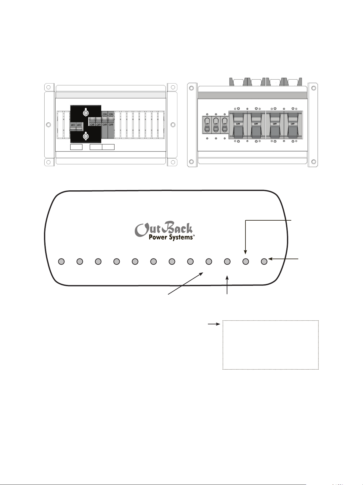
Componentes y conexiones:
BYPASS OUTPUT INPUT
1. Con todos los interruptores de CA y CC en posición de apagado (OFF), conecte todos los FX al HUB con tramos
individuales de cable CAT 5.
Interruptores de CA en posición de apagado (OFF) Interruptores de CC en posición de apagado (OFF)
El puerto
POWER HUB
“2nd MATE”
(2.º MATE)
no está en
condición
operable
El MATE
10 9 8 7 6 5 4 3 2 1
nd
2
Mate
st
1
Mate
se conecta
al puerto
“1st MATE”
(1.º MATE)
Los FX esclavos se enchufan en los puertos 02 en adelante.
El FX conectado al puerto 01 siempre
se programa como el maestro.
Los controladores de carga de OutBack se pueden
enchufar en cualquier puerto, una vez que se haya
conectado el último FX.
• El FX maestro siempre se considera
la Rama n.º 1 o la fase L-1.
a) Conecte el MATE de OutBack después de haber conectado
y encendido todos los otros componentes, incluidos los
controladores de carga de OutBack.
b) Si se instalan componentes después de haber encendido el
sistema, se deberá repetir la secuencia de sondeo inicial del MATE
(consulte la página 8).
c) Con el dispositivo MATE, el usuario asigna un estado y un valor de
apilamiento al FX de cada puerto. Estas asignaciones de estado
y valor pueden modicarse en cualquier momento, siempre
y cuando el FX maestro esté enchufado al puerto 01 del HUB.
NOTA: Preste atención al número de puerto de la pantalla. Asegúrese de estar modicando el estado
y el valor de apilamiento del FX indicado.
4
Page 7
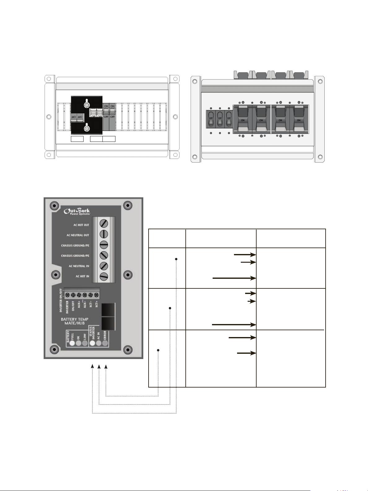
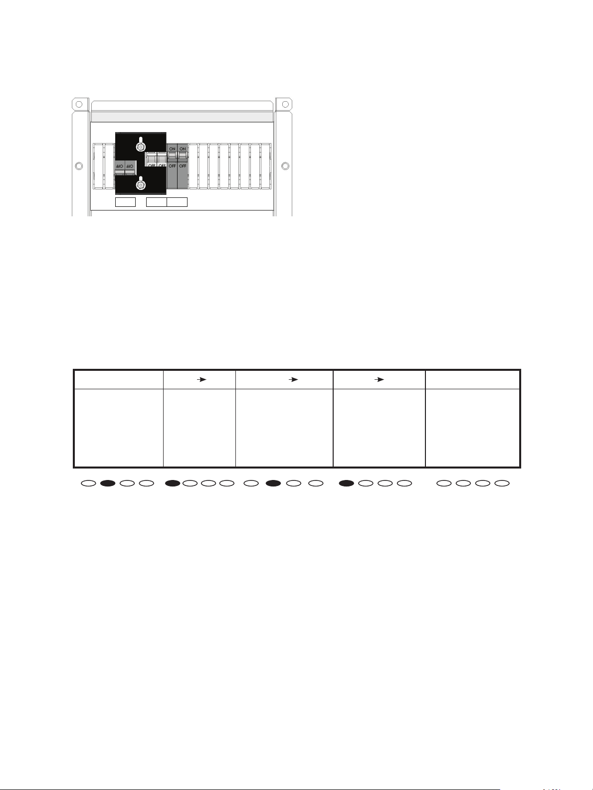
2. Con los FX conectados al HUB, ubique solamente los interruptores de CC en la posición de encendido (ON)
BYPASS OUTPUT INPUT
y encienda los componentes. Todos los interruptores de CA deben permanecer en la posición de apagado (OFF).
Interruptores de CA en posición de apagado (OFF) Interruptores de CC en posición de encendido (ON)
Color de LED Estado de LED LED indica
Verde VERDE continuo Inversor encendido
VERDE intermitente
alimentación esclava
Modo de búsqueda o
Apagado Inversor apagado
Amarillo AMARILLO continuo Fuente de CA conectada
AMARILLO
intermitente
Entrada de CA energizada,
en espera de conexión al
FX
Apagado Sin entrada de CA
Rojo ROJO continuo Error: Mensaje de error,
se muestra en el MATE
ROJO intermitente Advertencia: Falla no
crítica en el FX. El MATE
puede obtener acceso
a esta información
NO TA: Al encender los FX, puede parpadear la luz de
estado “ERROR”. Después de 5 a 10 segundos, deben
encenderse la luz verde “INVERTER” (inversor) y apagarse las
luces “ERROR” y “AC IN” (entrada de CA). En ese momento, el
FX comenzará a producir voltaje de salida de CA.
5
Page 8
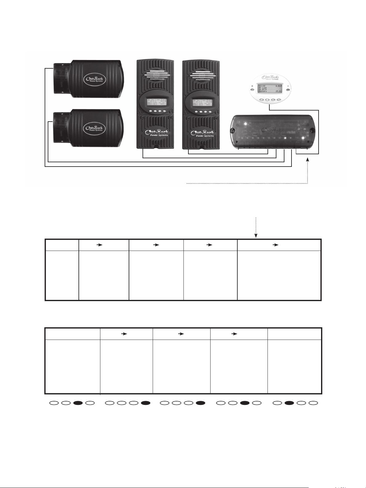
3. Una vez encendidos los componentes, conecte el MATE al HUB.
a) Enchufe el MATE en el puerto “1st MATE” del HUB.
b) El MATE se encenderá y debería reconocer a todos los componentes conectados al HUB.
c) A continuación, el MATE podrá usarse para programar los FX.
d) La quinta pantalla del MATE, “Port Assignment” (asignación de puertos), debe mostrar todos los FX
y controladores de carga de Outback del sistema.
Pantallas del MATE
RUTA
G’day Mate (C) 2008 Version Searching Port Assignment
OutBack Code a.aa for Devices 1> FX 2> FX 3> CC 4> CC
Power 5> 6> 7> 8>
Systems Serial #xxxxxxxx HUB Found 9> 10> 2M>
Screen EE b.bb
4. Para comprobar que el MATE reconozca todos los FX y controladores de carga de OutBack conectados al HUB,
desconecte el MATE y, a continuación: (a) vuelva a conectar el MATE para ver la secuencia de arranque y sondeo
inicial; o (b) siga esta ruta para ejecutar la secuencia de sondeo inicial manualmente:
RUTA
M
AIN------------------- SETUP----------------- SETUP/MATE/PAGE1 SETUP/MATE/PAGE2 SETUP/MATE/COMM
12.15:30p mate code rev: 4.1.6 choose category: choose category:
choose device: choose category:
SUM STATUS SETUP ADV FX MATE CLOCK CNT GLOW PG2 PG1 SUMRY COMM MAIN BACK REPOLL PC DEBUG
Los FX estarán listos para programarse según las opciones de apilamiento descritas en la sección siguiente.
6
Page 9
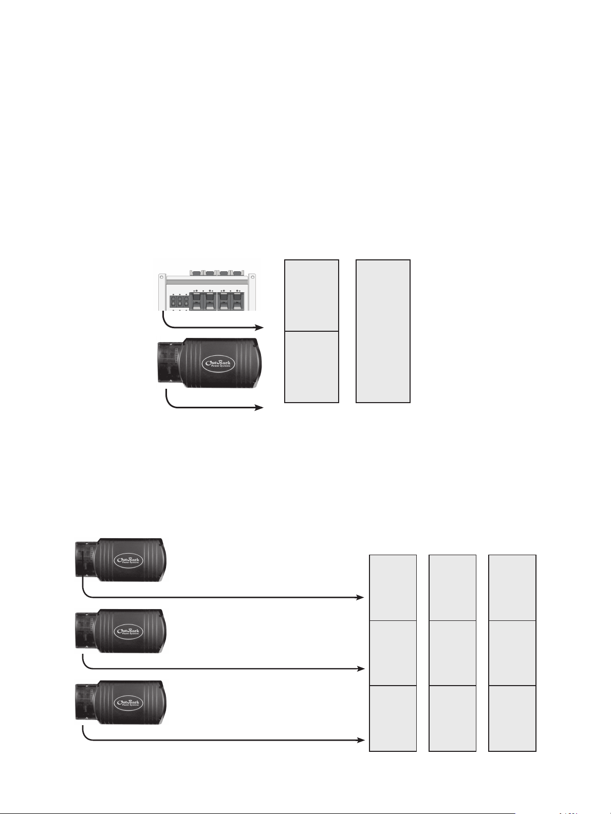
OPCIONES DE APILAMIENTO
Los FX interactivos con la red de OutBack sólo pueden apilarse en serie o en tres fases.
EN SERIE
• Se conectan dos FX a dos ramas de salida de 120 V CA, que producen 240 V CA entre las dos.
• Cada FX alimenta una rama y actúa de forma independiente, pero ambos se combinan si una carga
exige 240 V CA.
• La entrada de CA debe ser de 240 V AC de fase dividida.
CARGA
3 kW
120 V CA
Rama 2
3 kW 120 V CA
3 kW
120 V CA
Rama 2
o
6 kW
240 V CA
Rama 1
y
Rama 2
3 kW 120 V CA
EN TRES FASES
• Se conectan tres (y sólo tres) FX, uno con cada rama de salida de 120 V CA, que producen un voltaje
nominal de 208 V CA entre dos ramas cualesquiera del sistema. (Los voltajes exactos son de 127 V CA por
rama y de 220 V CA entre dos ramas).
• La entrada de CA (generador o red) debe provenir de una fuente trifásica de 120 V CA/208 V CA.
CARGA
3 kW 120 V CA
3 kW 120 V CA
Fase A
120 V CA
3 kW
Fase B
120 V CA
3 kW
Dos ramas
cualesquiera*
208 V CA
6 kW
*A y B
A y C
o
B y C
En tres fases,
las tres
ramas, 9 kW
o
3 kW 120 V CA
Fase C
120 V CA
3 kW
7
Page 10

APILAMIENTO Y ASIGNACIÓN DE ESTADOS DE FX
Use el dispositivo MATE para establecer el orden o la jerarquía de todos los FX del sistema, asignándole
a cada FX una de las siguientes categorías (se presentan en el orden en que aparecen en el MATE):
• Master (maestro), para apilamiento en serie o en tres fases
• Classic Slave (esclavo clásico), para apilamiento en serie
• 3p Classic B (fase B clásica en tres fases), para apilamiento en tres fases
• 3p Classic C (fase C clásica en tres fases), para apilamiento en tres fases
También se mostrarán otras opciones, pero éstas no son compatibles con este modelo de FX.
Master
• Esta categoría es la predeterminada para todos los FX.
• Se debe establecer un FX maestro en todos los sistemas de varios FX. Esto es válido para los sistemas
de una, dos y tres fases.
• Todos los FX interactivos con la red pueden ser maestros, siempre y cuando cada uno esté
conectado a una batería separada y a una rama de salida de CA separada (tanto los conectores
neutros como los con corriente).
• Si un FX interactivo con la red se designa como único maestro del sistema, siempre se lo considera la
fase Rama 1.
Classic Slave
• La categoría de esclavo clásico designa al segundo FX de un sistema de dos inversores y de fase
dividida que produce 240 V CA.
• Este FX se enchufa en el puerto 02 del HUB y se lo considera la fase L2.
3p Classic B
• En el apilamiento en tres fases, la unidad enchufada al puerto 02 del HUB (fase B) se considera la fase
B clásica en tres fases.
3p Classic C
• En el apilamiento en tres fases, la unidad enchufada al puerto 03 del HUB (fase C) se considera la fase
C clásica en tres fases.
8
Page 11
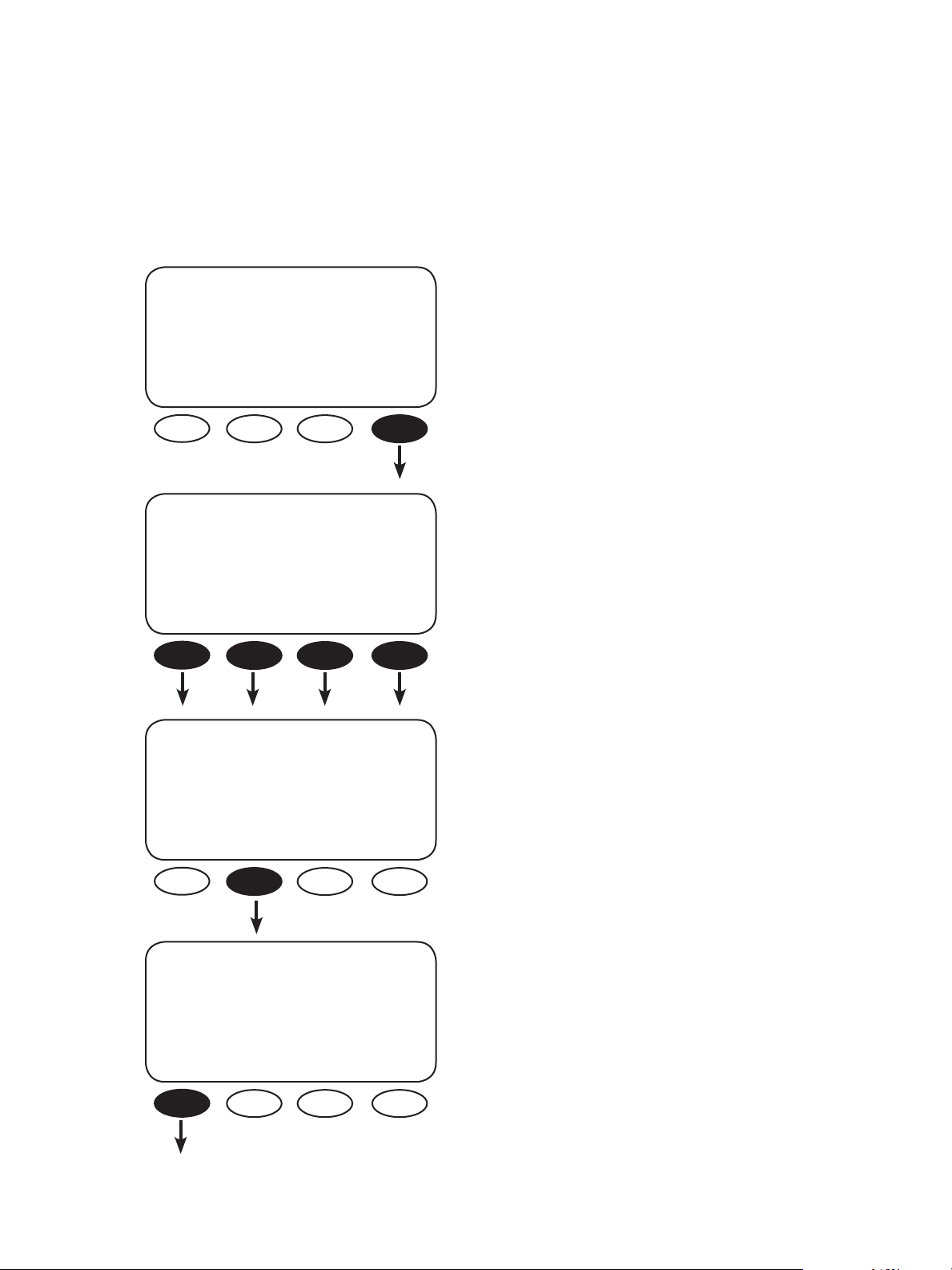
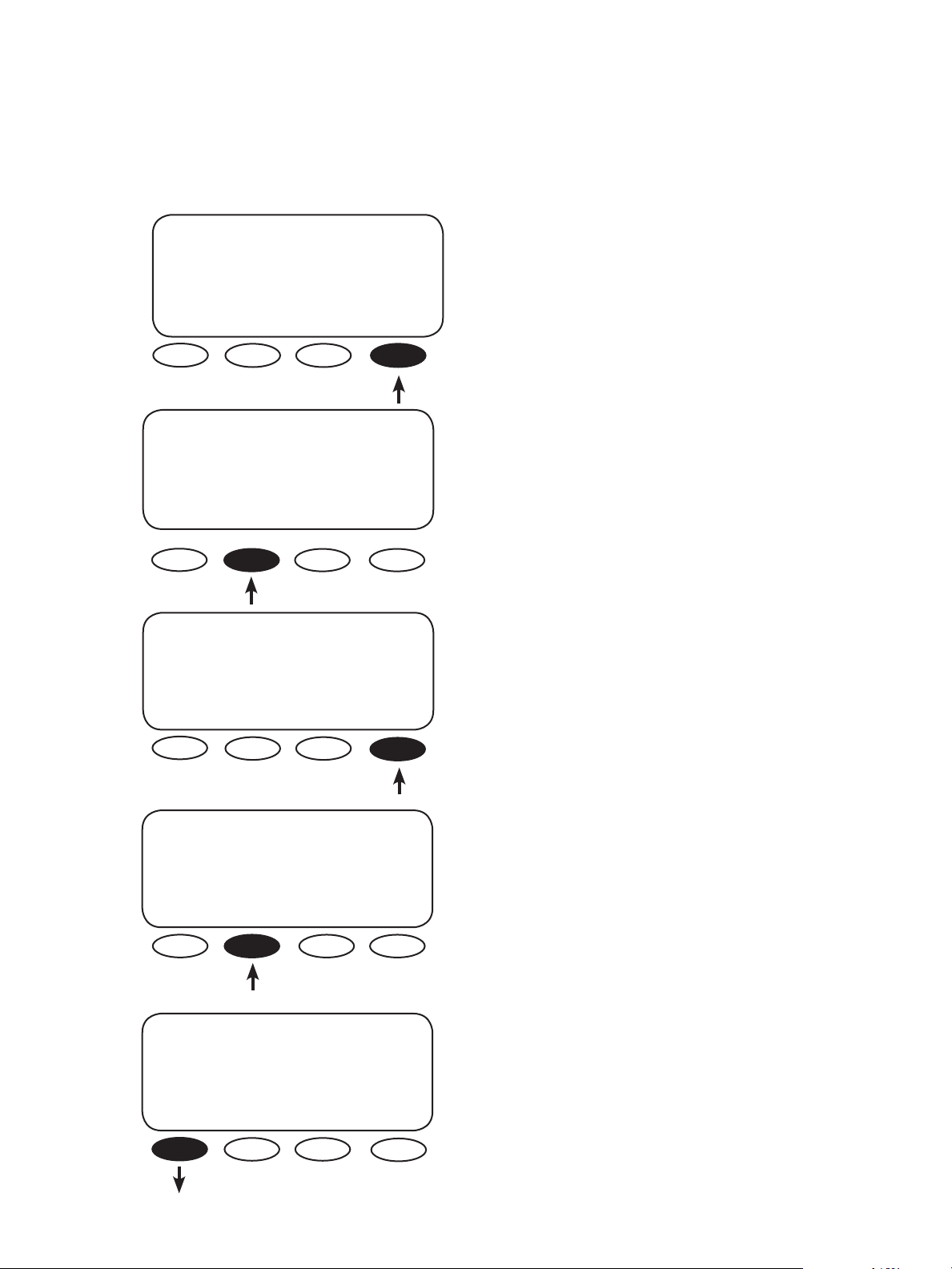
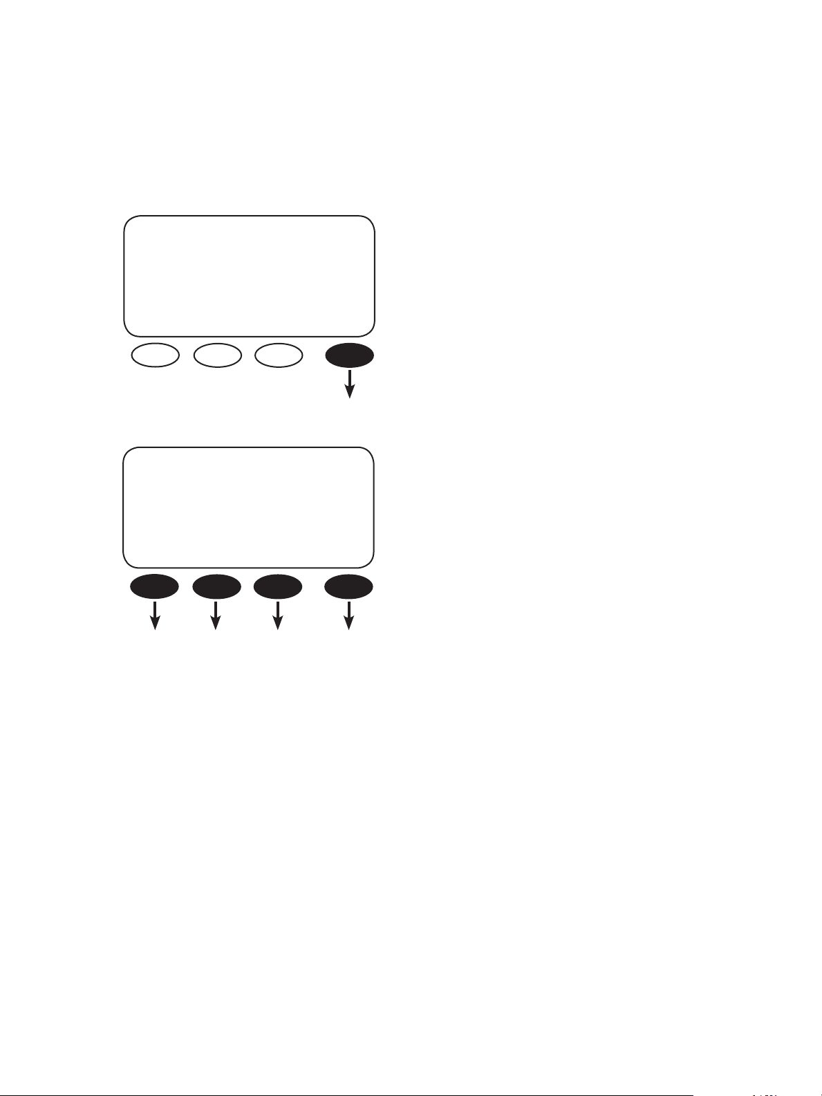
PROGRAMACIÓN DE LOS FX
Una vez que el MATE haya reconocido todos los FX (y los controladores de carga de OutBack),
mantenga presionadas simultáneamente las dos primeras teclas programables para volver al menú
principal. Para programar los FX, siga estos pasos para ir al menú ADV/FX/STACK del MATE:
MAIN--------------------------
• Presione la tecla programable <ADV>.
12:12:16A
NOTA: Si mantiene presionadas en simultáneo las
SUM STATUS SETUP ADV
ADV/SETTINGS/WARNING
dos primeras teclas programables, siempre saldrá
al menú principal.
changes made could adversely aect
system performance
ADV/PASSWORD
enter the password
132
ENTER INC DEC EXIT
ADV/PASSWORD
enter the password
141
• Presione cualquier tecla programable en la pantalla
ADV/SETTINGS/WARNING para pasar a la pantalla
ADV/PASSWORD.
• La pantalla mostrará <132>. Presione el botón
<INC> hasta llegar a la contraseña, 141.
• Presione la tecla programable <ENTER>.
ENTER INC DEC EXIT
9
Page 12
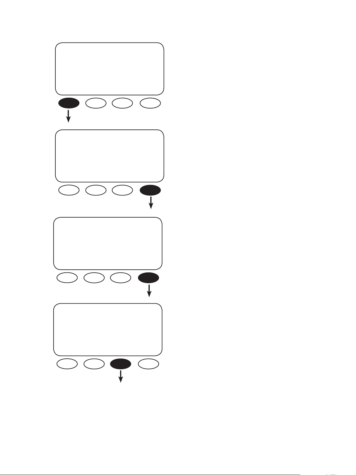
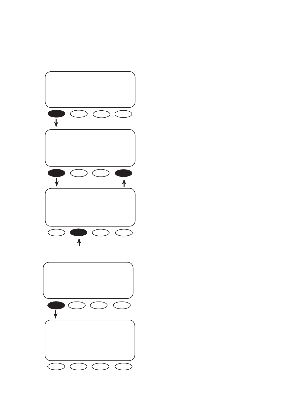
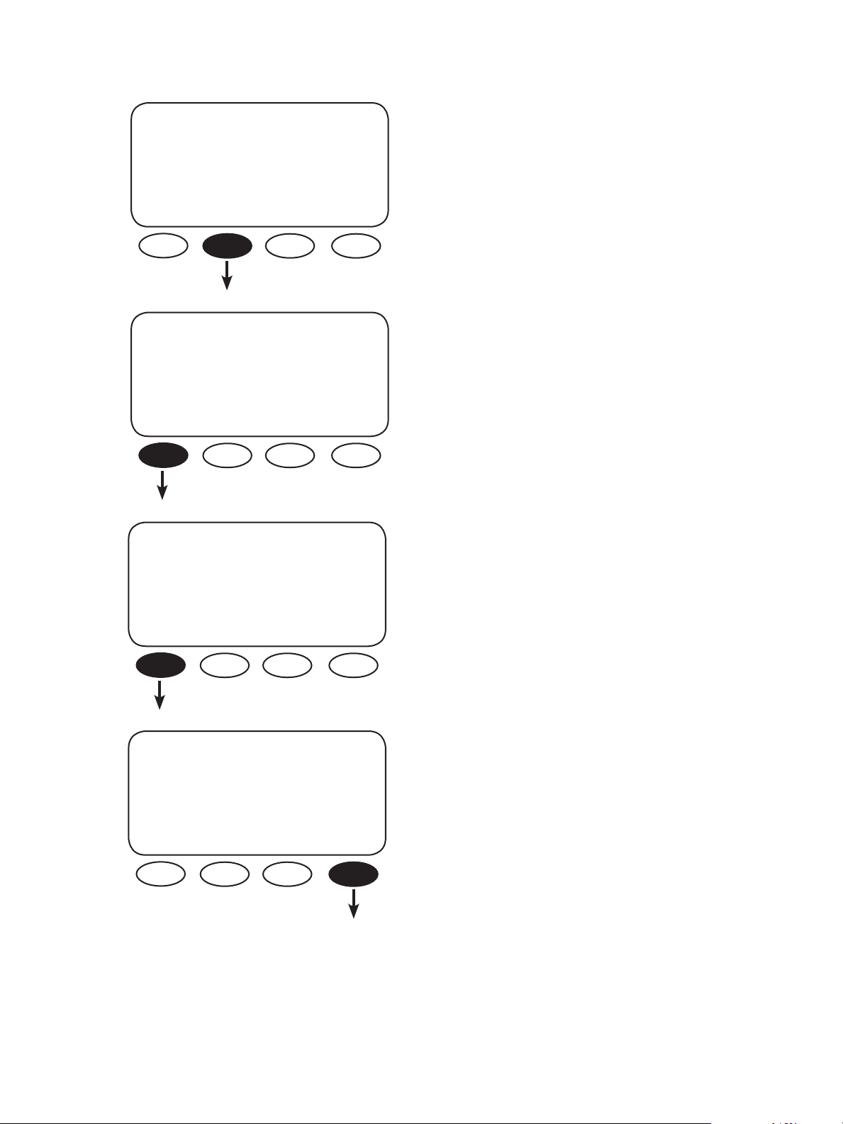
ADV
choose device:
FX CC DC MATE
ADV/FX/PAGE 1----------------
choose category:
ADV INV CHGR PG2
• En el menú ADV, presione la tecla programable <FX>.
• En la pantalla ADV/FX/PAGE 1, presione la tecla
programable <PG2> para pasar a la pantalla ADV/
FX/PAGE2.
ADV/FX/PG2-------------------
choose category:
PG1 GRID GEN PG3
ADV/FX/PAGE3----------------
choose category:
PG2 AUX STACK PG4
• Presione la tecla programable <PG3> para ir
a la pantalla ADV/FX/PAGE3.
• En la pantalla ADV/FX/PAGE3, presione la tecla
programable <STACK>.
10
Page 13
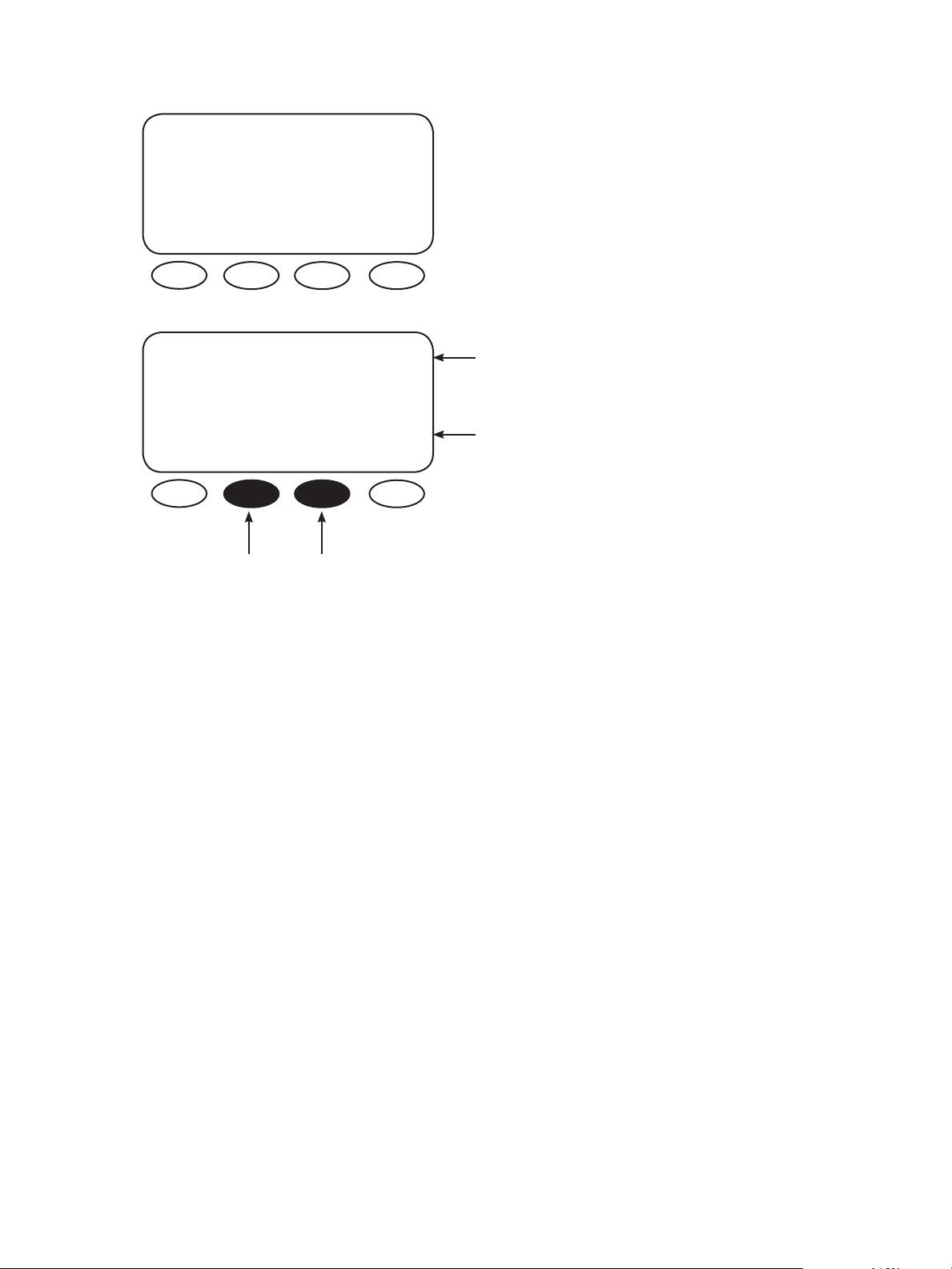
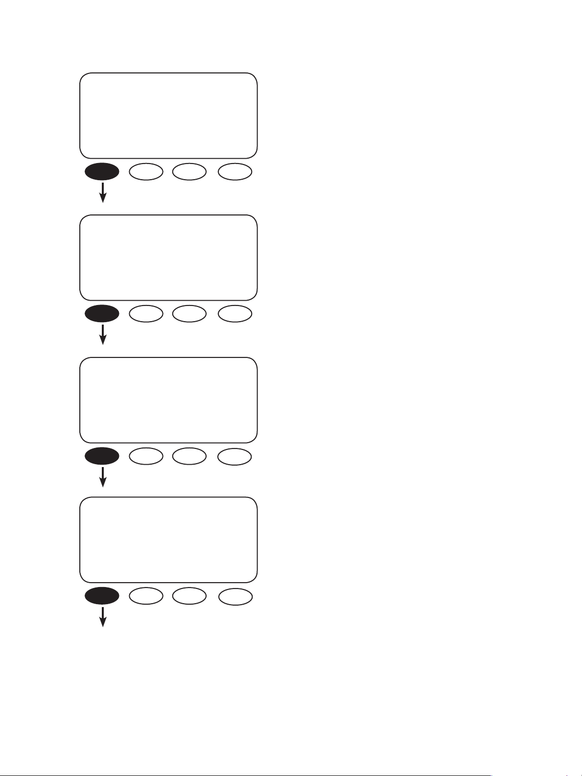
ADV/FX/STACK--------P01
stack Master
phase
DOWN INC DEC PORT
• El apilamiento de los inversores/cargadores
FX comienza en esta pantalla. Consulte los
procedimientos especícos de apilamiento en la
sección siguiente.
ADV/FX/STACK----------P01
stack Master
phase
DOWN INC DEC PORT
Al presionar las teclas programables <INC>
o <DEC>, se cambia la fase de apilamiento.
• El FX conectado al puerto 01 siempre se ajusta
como maestro.
• Presione la tecla programable <PORT> hasta llegar
al puerto del HUB cuyo valor se desee ajustar.
11
Page 14
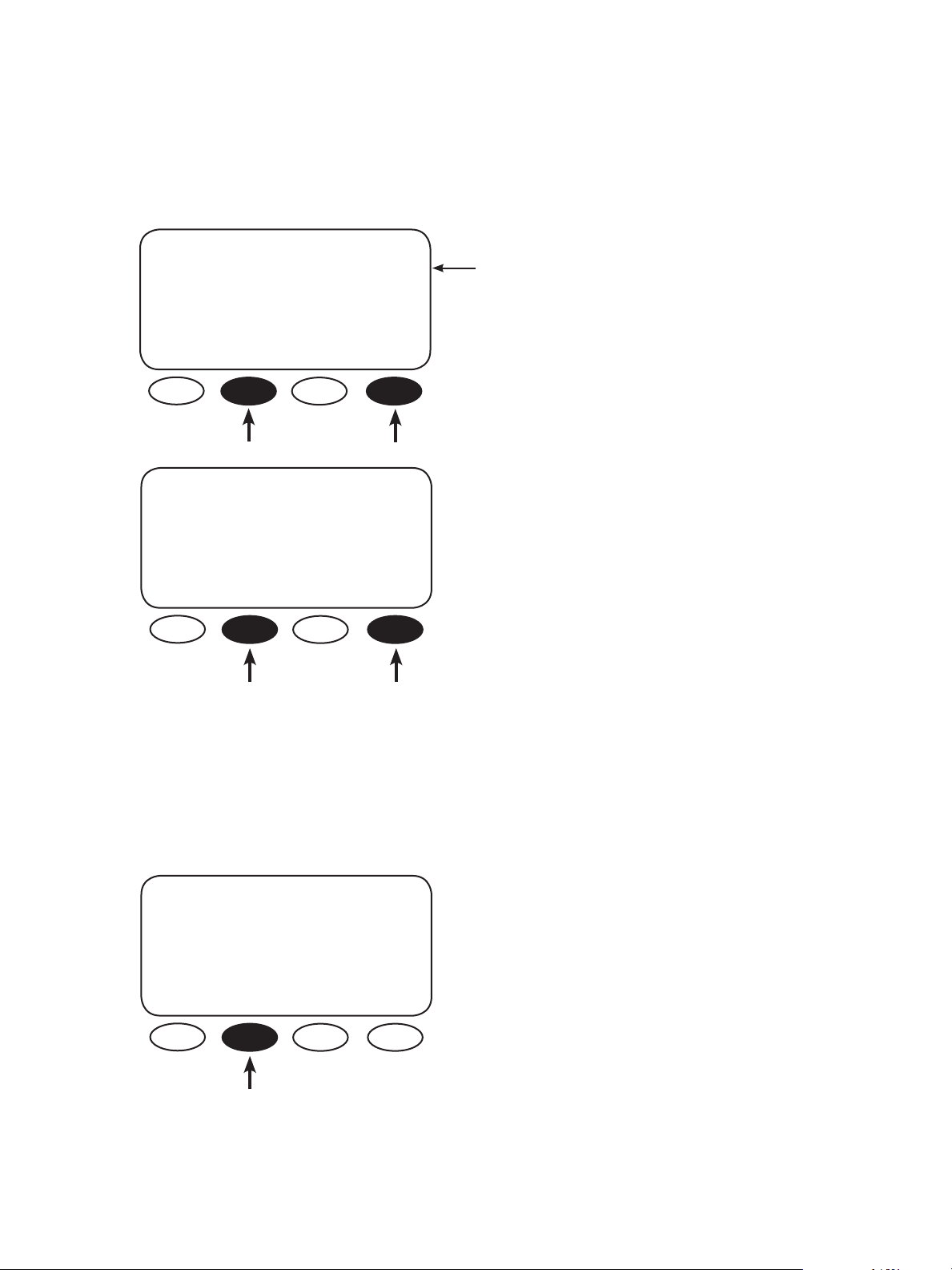
MAESTRO
Una vez que el FX del puerto 01 esté congurado como maestro, presione la tecla programable
<PORT> para cambiar los otros puertos y designar los otros FX como esclavos. La pantalla del MATE
para el puerto 02 se verá así:
ADV/FX/STACK--------P02
stack Master
phase
DOWN INC DEC PORT
ADV/FX/STACK---------P02
stack Master
phase
DOWN INC DEC PORT
• El MATE ya quedará listo para programar el FX
enchufado en el puerto 02 del HUB.
• La categoría de maestro es el valor predeterminado
para todos los FX interactivos con la red.
• Al presionar la tecla programable <INC>, la
pantalla del MATE se mantendrá en el puerto
02, pero se cambiará la fase de apilamiento a la
pantalla Classic Slave. En consecuencia, el puerto
02 quedará asignado como esclavo clásico. Puede
cambiar la fase de apilamiento si presiona las
teclas programables <INC> o <DEC>, y pasar a
otros puertos si presiona continuamente la tecla
programable <PORT>.
NOTA: No hay comandos tipo <ACEPTAR> o <LISTO> en el menú de apilamiento. El valor que se
muestre en la pantalla del MATE (Master o Classic Slave) quedará asignado al puerto y al FX elegidos
al salir de la pantalla. Es importante controlar el número de puerto en la esquina superior derecha de
cada pantalla, para asegurarse de haberle asignado el estado deseado.
ESCLAVO CLÁSICO
ADV/FX/STACK---------P02
stack Classic Slave
phase
• El puerto P02 quedará asignado como esclavo clásico.
DOWN INC DEC PORT
12
Page 15
FASE B CLÁSICA EN TRES FASES
• Asegúrese de que los dos inversores esclavos estén en los puertos 02 y 03 del HUB. El inversor del
puerto 02 del HUB se considera la fase B.
El inversor del puerto 03 del HUB se considera la fase C
ADV/FX/STACK----------P01
stack Master
phase
• En la pantalla Master, presione la tecla programable
<PORT> hasta que aparezca P02.
DOWN INC DEC PORT
ADV/FX/STACK-----------P02
stack Master
phase
DOWN INC DEC PORT
ADV/FX/STACK----------P02
stack 3p Classic B
phase
DOWN INC DEC PORT
ADV/FX/STACK----------P03
stack Master
phase
DOWN INC DEC PORT
• Todas las pantallas de puertos nuevos se abrirán
en el menú de apilamiento con el ajuste Master en
pantalla. Para cambiar la opción de apilamiento,
presione la tecla programable <INC> hasta que
aparezca 3p Classic B.
• Después de establecer el puerto 02 en 3p Classic B,
presione la tecla programable <PORT> para pasar al
puerto 03.
• Al igual que el anterior, el puerto 03 se abrirá con
el ajuste Master en pantalla. Presione la tecla
programable <INC> hasta que aparezca 3p Classic C.
ADV/FX/STACK----------P03
stack 3p Classic C
phase
DOWN INC DEC PORT
• Una vez que haya terminado, presione la tecla
programable <DOWN>. Esto permitirá observar los
niveles de almacenamiento de energía o salir al menú.
13
Page 16
NIVELES DE ALMACENAMIENTO DE ENERGÍA
En los modelos interactivos con la red, los niveles de almacenamiento de energía afectan las funciones de
venta y carga. El inversor maestro se congura con el nivel de almacenamiento de energía más bajo, lo que
implica que siempre entrará en acción primero. Los esclavos deben congurarse con niveles más altos, para
que ayuden al maestro según sea necesario durante la carga o la venta de energía.
ADV/FX/STACK------------P01
(CUALQUIER PANTALLA DE LA
FASE DE APILAMIENTO)
DOWN INC DEC PORT
ADV/FX/STACK-----------P01
power save level 0
master adjust only
DOWN INC DEC PORT
ADV/FX/STACK---------P02
power save level 2
slave adjust only
DOWN INC DEC PORT
• Presione la tecla programable <DOWN> una vez
para ver la pantalla “power save level master adjust
only” (ajustar solamente el nivel de almacenamiento
de energía del maestro).
• El valor predeterminado para el inversor maestro
es de 0. Este valor no debe modicarse. Presione
la tecla programable <DOWN> para ver la pantalla
“power save level slave adjust only” (ajustar
solamente el nivel de almacenamiento de energía
del esclavo). A continuación, presione la tecla
programable <PORT> para ver el inversor esclavo,
P02 (y P03 si está presente).
• Presione la tecla programable <INC> para cambiar el
nivel de almacenamiento de energía de los inversores
esclavos. P02 debe congurarse en 1. Si el P03 está
presente, repita estos pasos y congúrelo en 2.
14
AJUSTES DE VENTA
ADV/FX/SELL-----------P01
sell re 26.0 vdc
volts
DOWN INC DEC PORT
ADV/FX/SELL-----------P01
grid tie USER
window
DOWN IEEE USER PORT
Hay dos ajustes importantes en el menú SELL (venta).
• “sell re volts” (vender voltios de energía renovable)
representa el nivel de voltaje al que el inversor/
cargador vende energía renovable (RE, por sus siglas
en inglés) a la red. Se recomienda que este ajuste
sea menor que los ajustes de la fuente de energía
renovable, pero que sea lo sucientemente alto
como para mantener bien la batería.
• La pantalla “grid tie window” (ventana de conexión
a la red) muestra dos opciones, pero el ajuste IEEE
no está disponible para este modelo de inversor. El
ajuste USER (usuario) es el único disponible.
Page 17
BYPASS OUTPUT INPUT
ENCENDIDO DE CA
• Una vez terminada la programación, ubique los
interruptores de salida de CA en la posición de
encendido (ON), con la opción BYPASS de CA del
panel del interruptor de CA en la posición NORMAL.
NOTA: Si usará el transformador automático FW-X240 para aumentar la salida, encienda el interruptor del
transformador en este momento. De lo contrario, pase a la etapa siguiente.
Compruebe la salida de voltaje de CA del MATE mediante esta ruta:
RUTA
MAIN------- SETUP------------ STATUS/FX/PAGE1---------- Invert Bulk P00 STATUS/FX/METER--P00
12.15:30p choose device: choose category: inv 0.0Kw zer 0.0kw output 127 vac
chg 0.0kw buy 0.0kw voltage
SUM STATUS SETUP ADV
FX CC DC MAIN MODES METER BATT PG2 DOWN STATUS PORT DOWN UP TOP PORT
15
Page 18
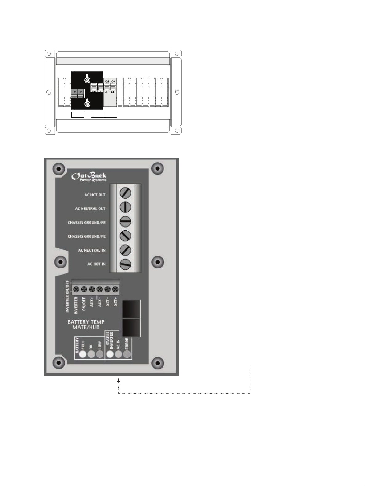
• Coloque los interruptores de entrada de CA en la
BYPASS OUTPUT INPUT
posición de encendido (ON).
16
Si la fuente de CA del FX está disponible, la luz amarilla
de estado “AC IN” parpadeará. El FX se conectará a la
red de distribución de energía eléctrica cuando el
voltaje sea de 100 V CA a 140 V CA y la frecuencia de
58 Hz a 62 Hz. Después de unos 30 segundos, la luz “AC
IN” debe dejar de parpadear y permanecer encendida.
Después de 12 segundos más, el FX podrá cargar una
batería con la energía de CA disponible.
Page 19
FUNCIONES AUXILIARES AUX
La salida auxiliar genera una salida máxima de 12 V CC, 0,7 A CC en los terminales auxiliares, para controlar las
cargas de CC o las cargas externas de CA si se usa un relé controlado por CC. Las cargas típicas incluyen el envío
de una señal de alarma por falla o la alimentación de un pequeño ventilador para enfriar el FX.
MAIN--------------------------
• Presione la tecla programable <ADV>.
12:12:16A
SUM STATUS SETUP ADV
ADV/SETTINGS/WARNING
changes made could
adversely aect
system performance
NOTA: Si mantiene presionadas en simultáneo las dos
primeras teclas programables, siempre saldrá al menú
principal.
• Presione cualquier tecla programable en la pantalla
ADV/SETTINGS/WARNING para pasar a la pantalla
ADV/PASSWORD.
17
Page 20
ADV/PASSWORD--------------
enter the password
132
ENTER INC DEC EXIT
ADV/PASSWORD----------------
enter the password
141
ENTER INC DEC EXIT
• La pantalla mostrará <132>. Presione el botón
<INC> hasta llegar a la contraseña, 141.
• Presione la tecla programable <ENTER>.
ADV------------------------------
choose device:
FX CC DC MATE
ADV/FX/PAGE 1----------------
choose category:
ADV INV CHGR PG2
• En el menú ADV, presione la tecla programable <FX>.
• En la pantalla ADV/FX/PAGE 1, presione la tecla
programable <PG2> para pasar a la pantalla
ADV/FX/PAGE2.
18
Page 21

ADV/FX/PAGE2------------------
choose category:
PG1 GRID GEN PG3
ADV/FX/PAGE3-----------------
choose category:
PG2 AUX STACK PG4
ADV/FX/AUX---------------P00
aux output AUTO
control
DOWN INC DEC PORT
• Presione la tecla programable <PG3> para ir a la
pantalla ADV/FX/PAGE3.
• En la pantalla ADV/FX/PAGE3, presione la tecla
programable <AUX> para congurar los puntos de
ajuste y el funcionamiento de la salida auxiliar.
Con las teclas programables <INC> o <DEC> se
puede cambiar el modo auxiliar.
• AUTO permite que se ejecute una función “aux
output function” (función de salida auxiliar) en el
modo auxiliar, que se puede elegir en las pantallas
siguientes.
OFF desactiva la salida auxiliar.
ON activa la salida auxiliar, independientemente de
la función seleccionada.
• Presione la tecla programable <DOWN> para
seleccionar una opción de “aux output function”.
ADV/FX/AUX--------------P00
aux output Cool Fan
function
DOWN INC DEC PORT
Al presionar las teclas programables <INC> o
<DEC>, se cambia la función auxiliar de salida.
Se pueden elegir nueve opciones diferentes en la
pantalla “aux output function”:
• Remote (remoto)
• Load Shed (depósito de carga)
• GenAlert (alerta de generador)
• Fault (falla)
• Vent Fan (ventilador de escape)
• Cool Fan (ventilador de enfriamiento)
• Divert DC (desviar CC)
• Divert AC (desviar CA)
• AC Drop (caída de CA)
Al presionar las teclas programables <INC> o <DEC>, se
pasará a otra función de la pantalla “aux output function”.
19
Page 22

LISTA DE FUNCIONES AUXILIARES AUX
• Cool Fan activa el turboventilador estándar que enfría el FX.
• Divert DC y Divert AC permiten a la salida auxiliar desviar el exceso de energía renovable a una carga de
CC o CA, respectivamente. Esto permite controlar fuentes de energía, como turbinas eólicas o generadores
hidroeléctricos. Si se usa la función Divert AC, la salida auxiliar se cerrará si el inversor se sobrecarga.
• AC Drop se activa cuando se desconecta una fuente de energía de CA del FX. Un indicador (como una
alarma) conectado a la salida auxiliar advierte al usuario que la energía de CA ya no está disponible.
• Vent Fan genera 0,7 amperios para alimentar un ventilador de 12 V CC, a n de eliminar el hidrógeno del
compartimiento de las baterías. Vent Fan puede activarse automáticamente cuando se supere el valor
establecido en “ventfan on setpoint” (punto de ajuste de encendido de ventilador de escape) o puede
activarse de manera intermitente mediante el ajuste “ventfan o period” (período de apagado de ventilador
de escape).
• En el modo Fault, la salida auxiliar puede enviar una señal de alarma mediante un dispositivo de radio,
localizador o teléfono cuando se produce un error en el FX. El modo Fault también puede usarse para
registrar errores mediante la activación de un dispositivo de registro de eventos.
• GenAlert, mediante un relé de 12 V CC, indicará al sistema que arranque un generador bilar cuando
el voltaje de la batería sea menor que el punto de ajuste seleccionado. GenAlert puede ajustarse según
el voltaje insuciente de la batería, el tiempo transcurrido a este voltaje, el voltaje recargado y el tiempo
transcurrido a este voltaje antes de que se desactive GenAlert.
• Load Shed activa la salida auxiliar para reducir la demanda de carga en las baterías y el inversor, y así
convertirse en un sistema de administración de cargas.
• Si la salida auxiliar se congura en Remote, se podrá enviar un mensaje por el puerto en serie del MATE para
encender y apagar la salida auxiliar.
NO TA: El uso de Arranque avanzado por generador (AGS) anula cualquier función auxiliar programada.
FUNCIONES AJUSTABLES DE SALIDA AUXILIAR AUX
El usuario puede ajustar cuatro de las funciones auxiliares:
• Diversion
• Vent Fan
• GenAlert
• Load Shed
Todos los ajustes de voltaje proporcionados hacen referencia a un inversor de 24 voltios.
ADV/FX/AUX-------------P00
aux output Remote
function
DOWN INC DEC PORT
• En la pantalla “Remote aux output function”
(función de salida auxiliar remota), presione la tecla
programable <DOWN>.
20
Page 23
ADV/FX/AUX-------------P00
aux output Remote
function
DOWN INC DEC PORT
• En la pantalla “Remote aux output function”, presione
la tecla programable <DOWN>. Aparecerá la primera
de varias pantallas que permitirán ajustar el modo
elegido para la función auxiliar.
ADV/FX/AUX---------------P00
genalert 23.0vdc
on setpoint
DOWN INC DEC PORT
ADV/FX/AUX---------------P00
loadshed 22.0 vdc
o setpoint
DOWN INC DEC PORT
ADV/FX/AUX---------------P00
ventfan 13.0 vdc
on setpoint
DOWN INC DEC PORT
• Las funciones de genalert on setpoint (punto de
ajuste de encendido de alerta de generador) suelen
usarse con los FX interactivos con la red. Presione la
tecla programable <DOWN> tres veces para pasar a
la pantalla “loadshed o setpoint” (punto de ajuste
de apagado de depósito de carga).
• La función loadshed o setpoint representa el voltaje
de la batería que activa la salida auxiliar para reducir
las cargas del inversor y la batería. Cuando el voltaje
de la batería esté por debajo de este valor durante tres
segundos, la salida auxiliar alimentará un relé de bobina
de CC para que desconecte una carga de CA. Una vez
activada esta función, el depósito de carga permanece
encendido por un mínimo de tres minutos. La función
loadshed o setpoint puede tener un valor de 20 V CC a
28 V CC, que se ajusta en incrementos de 0,1 V CC con las
teclas programables <INC> y <DEC>. Presione la tecla
programable <DOWN> para pasar a la pantalla “ventfan
on setpoint” (punto de ajuste de encendido de ventilador
de escape).
• Cuando la salida auxiliar se congura en la opción
“ventfan on setpoint”, un ventilador de escape hace
circular aire por el compartimiento para baterías. La
función ventfan on setpoint establece el voltaje de la
batería que activa la salida auxiliar y alimenta el ventilador
durante un minuto. El voltaje puede congurarse con un
valor de 20 V CC a 32 V CC, que se ajusta en incrementos
de 0,1 V CC con las teclas programables <INC> y <DEC>.
La recarga hace que las baterías emitan principalmente
gas hidrógeno; a mayores voltajes de recarga, se emite
mayor cantidad de gas. Presione la tecla programable
<DOWN> para pasar a la pantalla “ventfan o period”.
21
Page 24

ADV/FX/AUX---------------P00
ventfan o 5 min
period
DOWN INC DEC PORT
ADV/FX/AUX---------------P00
diversion 14.6 vdc
on setpoint
DOWN INC DEC PORT
• Si el ventilador de escape se necesita sólo de manera
intermitente, la función ventfan o period apaga el
ventilador por un período determinado por el usuario,
antes de volver a encenderse por un minuto si el voltaje
de la batería supera el valor de la función “ventfan on
setpoint”. Este período de apagado puede congurarse
con un valor de 0 a 30 minutos, que se ajusta en
incrementos de un minuto con las teclas programables
<INC> y <DEC>. Si este período se congura en cero,
el ventilador permanecerá encendido todo el tiempo
mientras el voltaje de la batería sea lo sucientemente
alto como para activar el ventilador de escape. Si se lo
congura en cinco minutos, el ventilador funcionará por
un minuto y se apagará por cinco minutos, hasta que el
voltaje de la batería descienda y el ventilador ya no sea
necesario. Presione la tecla programable <DOWN> para
pasar a la pantalla “diversion on setpoint” (punto de ajuste
de encendido de desviación).
• Si se elige la función Divert DC o Divert AC, la pantalla
“diversion on setpoint” servirá para elegir el voltaje
que activará esta función auxiliar de salida. Esta función
puede tener un valor de 24 V CC a 32 V CC, que se ajusta
en incrementos de 0,1 V CC con las teclas programables
<INC> y <DEC>. Presione la tecla programable
<DOWN> para pasar a la pantalla “diversion o delay”
(demora de apagado de desviación).
ADV/FX/AUX--------------P00
diversion 30 sec
o delay
DOWN INC DEC PORT
• La función diversion o delay determina el período que
permanecerá activada la salida auxiliar una vez que el
voltaje de la batería que provocó la desviación sea menor
que el valor de la función diversion on setpoint. Esta
demora puede tener un valor de 0 a 240 segundos, que
se ajusta en incrementos de un segundo con las teclas
programables <INC> y <DEC>.
22
Page 25

INSTRUCCIONES PARA CARGAR BATERÍAS
Es muy importante mantener el banco de baterías cargado. Los bancos de baterías pueden durar
muchos años si están bien cuidados, pero pueden arruinarse en poco tiempo si se los descuida.
Puntos de ajuste de carga de baterías
Para preservar las baterías, siga siempre las recomendaciones del fabricante de las baterías con respecto a
la siguiente información:
• Voltaje de absorción
• Voltaje de mantenimiento
• Voltaje de carga y ecualización
• Nivel de descarga (ND) recomendado de las baterías
Estos puntos de ajuste del voltaje de absorción, mantenimiento, y carga y ecualización deben
programarse en el FX con el MATE (consulte el manual del usuario del MATE).
MANTENIMIENTO
Comuníquese con el servicio técnico de OutBack Power Systems si el FX debe repararse por mal
funcionamiento o daños. Para las tareas de mantenimiento de rutina que pueda realizar el usuario:
• Desconecte todos los interruptores de circuito y las conexiones eléctricas relacionadas antes de
limpiar o realizar ajustes.
• Los módulos solares pueden producir voltajes peligrosos al exponerse a la luz; cúbralos con material
opaco antes de realizar el mantenimiento de cualquier equipo conectado.
• Si se utiliza un sistema de arranque remoto, desactive el circuito automático de arranque mientras
realiza mantenimiento, para evitar que se ponga en marcha accidentalmente.
23
Page 26

Sistema de 12 V CC
PREDETERMINADO
MÍNIMO
MÁXIMO
Voltaje de mantenimiento
Voltaje de absorción
Voltaje de carga y ecualización
Voltaje de mantenimiento repetido
LBCO
LBCI
Venta de energía renovable
GenAlert (alerta de generador)
Punto de ajuste de apagado
Punto de ajuste de encendido
Punto de ajuste de apagado de depósito de carga
Punto de ajuste de encendido de ventilador de
escape
Punto de ajuste de encendido de desviación
Tiempo de absorción
Tiempo de carga y ecualización
Tiempo de mantenimiento
Demora de transferencia CA2/Gen (ciclos de CA)
Sensibilidad de búsqueda
Límite inferior de red
Límite superior de red
Demora de conexión a red
Caída o uso
Cargador apagado/automático/encendido
Opción de salida auxiliar
Demora de encendido de alerta de generador
Demora de apagado de alerta de generador
Demora de apagado de ventilador de escape
Límite inferior de ventana del generador
Límite superior de ventana del generador
Demora de transferencia CA1/Red (ciclos de CA)
Ajuste de control auxiliar
Pulsos de búsqueda
Separación de pulsos de búsqueda (ciclos de CA)
Fase de apilamiento
Selección de entrada
Tasas de carga de unidades con ventilación
de 24 V CC y 48 V CC
Tasas de carga de unidades selladas
de 24 V CC y 48 V CC
Ajustes de entrada de red
Ajustes de entrada de generador
Ajuste de V CA
13,6 V CC
14,4 V CC
14,6 V CC
12,5 V CC
10,5 V CC
12,5 V CC
13,0 V CC
14 V CC
11 V CC
11 V CC
13 V CC
14,6 V CC
1 hora
1 hora
1 hora
10 ciclos
6 vatios
114 V CA
140 V CA
0,5 min
USE (uso)
AUTO (automático)
COOL FAN
(ventilador de
enfriamiento)
4 min
9 min
5 min
114 V CA
140 V CA
6
AUTO (automático)
8
60
Master (maestro)
Grid (red)
18 A de CA
14 A de CA
50 A
30 A
127 V CA
12 V CC
13 V CC
14 V CC
12 V CC
9 V CC
10 V CC
10 V CC
12 V CC
10 V CC
10 V CC
10 V CC
12 V CC
0 horas
0 horas
0 horas
0 ciclos
0
100 V CA
130 V CA
0,2 min
N/C
0 min
0 min
0 min
100 V CA
130 V CA
0
2
4
0 A de CA
0 A de CA
5 A
2 A
110 V CA
15 V CC
16 V CC
17 V CC
13 V CC
12 V CC
14 V CC
15 V CC
18 V CC
14 V CC
14 V CC
16 V CC
16 V CC
24 horas
24 horas
24 horas
240 ciclos
50 vatios
120 V CA
140 V CA
15 min
N/C
240 min
240 min
30 min
120 V CA
140 V CA
240
20
120
20 A de CA
16 A de CA
60 A
60 A
130 V CA
24
Factor de corrección
24 V CC: Multiplicar por
2 los valores de 12 V CC
48 V CC: Multiplicar por
4 los valores de 12 V CC
Valores predeterminados del FX (pueden cambiar con las mejoras del FX)
Page 27

25
Page 28

INFORMACIÓN SOBRE LA GARANTÍA LIMITADA POR DOS AÑOS
Inversores/cargadores serie FX
OutBack Power Systems, Inc. (“OutBack”) proporciona una garantía limitada por dos (2) años (“Garantía”) contra
defectos en los materiales y la mano de obra para los inversores/cargadores serie FX/VFX (“Productos”) que se
instalen en aplicaciones de ubicación ja.
El plazo de esta Garantía comienza en la fecha de fabricación de los Productos o en la fecha inicial de compra que
aparece en la tarjeta de registro de garantía enviada a OutBack, la que sea posterior. Esta Garantía se otorga al
comprador original de los Productos de OutBack, y es transferible sólo si los Productos permanecen instalados en
el lugar original de uso. La Garantía no abarca los Productos o piezas de Productos que hayan sido modicados o
dañados por las siguientes causas:
• Instalación o desinstalación.
• Alteración o desmontaje.
• Desgaste por uso normal.
• Accidente o uso indebido.
• Corrosión.
• Rayos.
• Tareas de reparación o mantenimiento realizadas en un centro de reparación no autorizado.
• Incumplimiento de las instrucciones de operación del fabricante del producto.
• Incendios, inundaciones o casos fortuitos.
• Envío o transporte.
• Daños accidentales o consecuentes ocasionados por otros componentes del sistema de suministro de energía.
• Cualquier producto cuyo número de serie haya sido alterado, destruido o quitado.
• Cualquier otro evento que no sea previsible para OutBack.
26
La responsabilidad de OutBack por cualquier Producto o pieza de Producto defectuosos se limitará a la reparación o el
reemplazo del Producto, a criterio de OutBack. OutBack no garantiza la mano de obra de ninguna persona o empresa
que instale sus Productos. Esta Garantía no cubre los costos de instalación, desinstalación, envío (excepto lo descrito a
continuación) o reinstalación de los Productos.
Revisión 2008-04-01
Page 29

Para solicitar mantenimiento en garantía, debe comunicarse con el servicio técnico de OutBack al (360) 435-6030
o a support@outbackpower.com dentro del período de vigencia de la garantía. El servicio técnico de OutBack
intentará localizar la falla para validar si está relacionada con el Producto. Si se debe realizar mantenimiento en
garantía, OutBack emitirá un número de Autorización de devolución de material (RMA). Para solicitar un número
de RMA, se debe proporcionar la totalidad de los siguientes datos:
1. Comprobante de compra, que puede ser una copia de la factura o recibo original de compra del Producto,
donde conste el número de modelo y el número de serie del Producto.
2. Descripción del problema.
3. Dirección postal del equipo que deberá repararse o reemplazarse.
Una vez recibido el número de RMA, embale los Productos autorizados para la devolución, junto con una copia
de la factura original de compra, en los contenedores de envío originales de los Productos o en embalajes
que ofrezcan un nivel de protección equivalente, e identique el exterior claramente con el número de RMA.
El remitente debe pagar por adelantado todos los costos de envío a la dirección convenida con OutBack
Power Systems, y asegurar el envío o asumir el riesgo de pérdida o daños durante el envío. OutBack no se hace
responsable de los daños que puedan producirse durante el envío por un embalaje incorrecto de los Productos,
ni de las reparaciones que estos daños puedan requerir, ni de los costos de estas reparaciones. Si, tras recibir los
Productos, OutBack determina que están defectuosos y que los defectos están cubiertos por los términos de esta
Garantía, OutBack recién entonces reparará o reemplazará los Productos y los enviará al comprador mediante un
ete sin urgencia pagado por adelantado, con la empresa de transporte que OutBack elija, si corresponde.
El período de garantía de cualquier Producto reparado o reemplazado será de doce (12) meses a partir de la
fecha de envío de OutBack, o corresponderá al porcentaje restante del plazo inicial de garantía, lo que sea mayor.
ESTA GARANTÍA LIMITADA ES LA ÚNICA GARANTÍA QUE CUBRE LOS PRODUCTOS DE OUTBACK. OUTBACK
NIEGA EXPRESAMENTE TODA OTRA GARANTÍA EXPRESA O IMPLÍCITA DE SUS PRODUCTOS, INCLUIDAS, ENTRE
OTRAS, LAS GARANTÍAS IMPLÍCITAS DE COMERCIALIZACIÓN E IDONEIDAD PARA UN PROPÓSITO DETERMINADO.
OUTBACK TAMBIÉN LIMITA EXPRESAMENTE SU RESPONSABILIDAD, EN CASO DE DEFECTOS EN LOS PRODUCTOS,
A LA REPARACIÓN O EL REEMPLAZO SEGÚN LOS TÉRMINOS DE ESTA GARANTÍA LIMITADA Y EXCLUYE TODA
RESPONSABILIDAD POR DAÑOS ACCIDENTALES O CONSECUENTES, INCLUIDA SIN LIMITACIONES CUALQUIER
RESPONSABILIDAD POR LA IMPOSIBILIDAD DE USAR LOS PRODUCTOS O EL LUCRO CESANTE O LA PÉRDIDA
DE INGRESOS, INCLUSO SI SE LE NOTIFICA DE ESTOS POSIBLES DAÑOS. ES POSIBLE QUE ALGUNOS ESTADOS O
JURISDICCIONES NO PERMITAN LA EXCLUSIÓN O LIMITACIÓN DE GARANTÍAS O DAÑOS, DE MODO QUE LAS
LIMITACIONES O EXCLUSIONES ANTERIORES PUEDEN NO APLICARSE EN SU CASO.
Revisión 2008-02-26
27
Page 30

GARANTÍA LIMITADA
REGISTRO
Garantía limitada y envíelo a la siguiente dirección:
Outback Power Systems Inc.
19009 62nd Ave. NE
Arlington, WA 98223
NOTA: Envíe una copia (no el original) de la factura de compra del Producto, para conrmar la fecha
y el lugar de compra, el precio abonado y el modelo y número de serie del Producto.
Complete este formulario para solicitar una
Registro de garantía limitada por dos años del FX
Propietario del sistema
Nombre: ______________________________ País: __________________________________
Dirección: _____________________________ Teléfono: ______________________________
Ciudad, estado, código postal: ____________ Correo electrónico: ______________________
Producto
Número de modelo de los Productos: _______ Vendedor: _____________________________
Número de serie de los Productos: _________ Fecha de compra:
Marque con un círculo los tres factores principales que inuyeron en su compra:
• Precio • Reputación del producto • Características del producto
• Reputación de OutBack Power Systems • Valor _______________________________
Sistema
Fecha de instalación o puesta en marcha del sistema:
Salida de CA nominal total del sistema en kW:___________________
Voltaje de CA nominal del sistema: __________________________________________________
Tamaño del banco de baterías del sistema (A/hora):______________
Tipo de baterías: ______________________
__________________________________
¿Se usa un generador con este sistema? (marque una opción con un círculo): Sí No
Si la respuesta es “Sí”, indique la marca y el modelo:_____________________________________
Si la respuesta es “Sí”, la salida del generador es de (marque una opción con un círculo): CA CC
__________________________________
______________________
_______________________
________
Instalador
Nombre (si corresponde): ________________ Dirección: _____________________________
Ciudad, estado, código postal: _____________ Correo electrónico: ______________________
Número de contratista: __________________
*Garantía extendida
OutBack Power Systems ofrece una extensión opcional de tres (3) años para la Garantía limitada estándar de dos
(2) años para el producto Inversor/cargador serie FX/VFX. Si desea solicitar una extensión de 3 años para la Garantía
limitada y contar con un período de vigencia total de la garantía de cinco (5) años, incluya un cheque o giro postal por
USD 300 a nombre de OutBack Power Systems, Inc. junto con el registro de garantía.
Revisión 2008-04-01
28
Revisión 2008-04-01
Page 31

29
Page 32

30
Ocina corporativa
19009 62nd Avenue NE
Arlington, WA USA
(+1) 360-435-6030
www.outbackpower.com
Ocina de Ventas en Europa
C/ Castelló, 17
08830 - Sant Boi de Llobregat
BARCELONA, España
+34.93.654.9568
900-0041-02-00 REV A
Page 33

GTFX AND GVFX
LA SERIES Grid-Interactive
INVERTER/CHARGER
Programming Manual
31
Page 34

About OutBack Power Systems
OutBack Power Systems is a leader in advanced energy conversion technology. Our products include
true sine wave inverter/chargers, maximum power point charge controllers, system communication
components, as well as breaker panels, breakers, accessories, and assembled systems.
Contact Information
Telephone: (+1) 360.435.6030 (North America) Fax: (+1) 360.435.6019
(+34) 93.654.9568 (Barcelona, Spain)
Address: North America European Sales Oce
19009 62nd Avenue NE C/ Castelló, 17
Arlington, WA USA 08830 - Sant Boi de Llobregat
BARCELONA, España
E-mail: Support@OutbackPower.com
Web: www.OutBackPower.com
Disclaimer
UNLESS SPECIFICALLY AGREED TO IN WRITING, OUTBACK POWER SYSTEMS:
(a) MAKES NO WARRANTY AS TO THE ACCURACY, SUFFICIENCY OR SUITABILITY OF ANY TECHNICAL OR
OTHER INFORMATION PROVIDED IN ITS MANUALS OR OTHER DOCUMENTATION.
(b) ASSUMES NO RESPONSIBILITY OR LIABILITY FOR LOSS OR DAMAGE, WHETHER DIRECT, INDIRECT,
CONSEQUENTIAL OR INCIDENTAL, WHICH MIGHT ARISE OUT OF THE USE OF SUCH INFORMATION. THE
USE OF ANY SUCH INFORMATION WILL BE ENTIRELY AT THE USER’S RISK.
Warranty Summary
OutBack Power Systems Inc. warrants that the products it manufactures will be free from defects in
materials and workmanship for a period of two (2) years subject to the conditions set forth in the
warranty detail found inside the back cover of this manual.
OutBack Power Systems cannot be responsible for system failure, damages, or injury resulting from
improper installation of their products.
Notice of Copyright
GTFX and GVFX LA Series Grid-Interactive Inverter/Charger Programming Manual
©March 2009 by OutBack Power Systems. All Rights Reserved.
Trademarks
OutBack Power is a registered trademark of OutBack Power Systems.
Date and Revision
May 2009, Revision A
32
Page 35

TABLE OF CONTENTS
Welcome to the OutBack Power Systems FX Series Inverter/Charger System ................................................34
Safety ....................................................................................................................................................................................................34
FX Series Inverter/Charger Programming ...............................................................................................................................35
Concerns ............................................................................................................................................................................................35
Options ................................................................................................................................................................................................35
Components and Connections .....................................................................................................................................................36
Stacking Options ....................................................................................................................................................................................39
Stacking And Assigning FX Status ...............................................................................................................................................40
Programming the FXs ..........................................................................................................................................................................41
Master & Classic Slave .................................................................................................................................................................44
3PH Master & 3PH Slave ............................................................................................................................................................45
Power Save Levels ..................................................................................................................................................................................46
Sell Settings ................................................................................................................................................................................................46
AC ON ........................................................................................................................................................................................................47
Auxiliary (AUX) Functions ..................................................................................................................................................................49
List of AUX Functions ..................................................................................................................................................................52
Adjustable AUX Output Functions .....................................................................................................................................52
Battery Charging .....................................................................................................................................................................................55
Maintenance .............................................................................................................................................................................................55
FX Default Values ....................................................................................................................................................................................56
Warranty .......................................................................................................................................................................................................58
Product Registration .............................................................................................................................................................................60
33
Page 36

WELCOME TO THE OUTBACK POWER SYSTEMS GTFX AND GVFX LA SERIES
GRIDINTERACTIVE INVERTER/CHARGER SYSTEM
The GTFX and GVFX Series Inverter/Chargers (also referred to as the FX series) oer a complete power conversion
system—DC to AC, battery charging, and an AC transfer switch—which provide complete grid-interactive service.
They can also be used in a stand-alone or back-up application. These systmems are designed for indoor or
enclosed locations.
The GTFX and GVFX LA series produces an output voltage of 127 VAC per inverter. These inverters have been
programmed to accept this voltage as the optimal amount from an AC source. This manual often refers to the
voltage as “120 VAC”. However, this is a nominal reference to the true level of 127 VAC.
NOTE: This product does not carry a UL1741 or ETL listing. It is not to be used in the United States,
Canada or Puerto Rico.
OutBack Power Systems does everything possible to assure the components you purchase will function properly
and safely when installed as instructed according to local and national electrical codes. Please read all of the following instructions and the instructions that come with any other OutBack components that make up your power
system.
GTFX and GVFX LA Series Grid-Interactive Inverter/Charger Installation Manual.
Grounding Instructions – Each FX should be connected to a grounded, permanent wiring system. For most
installations, the negative battery conductor should be bonded to the grounding system at one (and only
one) point in the DC system. All installations must comply with all national and local codes and ordinances.
System grounding is the responsibility of the system installer.
Further instructions on individual FX set-ups as well as systems assemblies are included with the
The equipment ground is marked with this symbol:
The GTFX and GVFX LA Series Grid-Interactive Inverter/Charger Programming Manual covers safety and the
programming or “stacking” of multiple FXs using the OutBack Power Systems MATE.
NOTE:
• An OutBack MATE is required to program the FXs beyond their default values.
• If an OutBack Charge Controller is in use, be sure to read its manual for optimum operation with the FX.
• When powered up, the GTFX/GVFX will automatically sense if a utility grid is present and then connect to it after a
30-second delay. There is an extra 12-second delay before battery charging starts. The inverter can sell power to the
grid after the batteries are charged.
IMPORTANT SAFETY INSTRUCTIONS
General Precautions
1. Use caution whenever working around electricity, electrical components, and batteries. There is always a potential
for shocks, burns, injury, and even death if an installer or user comes in contact with electricity.
2. Read all instructions and cautionary markings on the FX, the batteries and all appropriate sections of this manual as
well as other component manuals before using the system.
3. Be sure each unit is securely installed according to the
Installation Manual.
4. Follow all local and national electrical codes when installing OutBack equipment and components.
GTFX and GVFX LA Series Grid-Interactive
Inverter/Charger
34
Page 37

GRIDINTERACTIVE FX SERIES INVERTER/CHARGER PROGRAMMING
NOTE: Please see the GTFX and GVFX LA Series Grid-Interactive
wire, and connect each FX Series Inverter/Charger. This programming manual assumes all FXs have
been installed and are ready to program according to the way they were wired. To familiarize yourself
with the programming concepts, please read through the entire manual before programming your
system.
• Stacking FXs does not refer to physically placing one FX on top of another. It refers to how they are
wired within the system and then programmed for operation. Stacking allows all the FXs to work
together as a single system.
• Stacking assigns the FXs to power individual legs of the system and to operate at certain times; this
order is assigned using the MATE.
: An OutBack MATE with a code revision of 3.30 or higher is required to recognize and program
NOTE
Grid-Interactive FXs. When multiple FXs are used, each needs to be assigned a status—Master or Slave
(at least one FX must be a Master).
• The Master FX is the primary and most heavily used unit. A Slave FX assists during charging or selling,
when the Master cannot handle all of the power..
• This is an orderly process as long as the user assigns each FX correctly. This is mainly a matter of
paying attention to the Port number for each FX when programming with the MATE.
Inverter/Charger Installation Manual
to install,
Stacking Concerns
FXs should be wired and stacked appropriately to their individual power system. Problems can occur
when:
• An FX is incorrectly wired.
• An FX plugged into a HUB Port is mistakenly programmed (assigned the wrong status) or
misidentied.
An easy rule to remember is any FX wired to a specic phase or leg must be programmed to that
phase.
Stacking Options
• The Grid-Interactive FX Series Inverter/Chargers can be stacked in Classic Series, or in Three-Phase.
Series stacking allows no more than two inverters in a system. Three-Phase stacking allows no more
than three inverters in a system.
• A HUB-4 or HUB-10 must be included to stack grid-interactive FXs. The Grid-Interactive FX cannot do
time-of-day selling.
• If the utility grid fails, the GTFX or GVFX seamlessly transfers the loads to the battery bank. When
the utility grid reappears, the Grid-Interactive FX automatically recharges the battery bank in case of
future power outages.
The FW-X240 Auto Transformer cannot be used for stacking with a Grid-Interactive FX system.
NOTE:
The FW-X240 can be used to step-up the AC output of a single Grid-Interactive FX system, however.
35
Page 38

Components and Connections:
BYPASS OUTPUT INPUT
1. With all AC and DC breakers OFF, connect all FXs to the HUB with individual lengths of CAT5 cable.
AC Breakers O DC Breakers O
POWER HUB
10 9 8 7 6 5 4 3 2 1
Slave FXs plug into Ports 02 and higher
The FX connected to Port
01 is always programmed
OutBack Charge Controllers plug into any
ports after the last FX is connected.
as the Master.
a) Connect the OutBack MATE after all other components,
including any OutBack Charge Controllers, have been
connected and powered up.
b) Components installed after powering up the system will
require repolling the MATE (please see page 8).
c) With the MATE, a user assigns a status and stacking value to
the FX on each Port. These status and value assignments can
be changed at any time as long as the Master FX is plugged
into HUB Port 01.
nd
2
MATE
port is not
operable
MATE
ND
2
Mate
st
1
Mate
connects
at 1st MATE
port
• The Master FX is always considered to
be the Leg #1 or L-1 phase.
NOTE: Pay attention to the Port number on the screen! Be sure the FX whose status and stacking value
you’re changing is the one you mean to change.
36
Page 39

2. With the FXs connected to the HUB, turn only the DC breakers ON and power up the components. All AC
BYPASS OUTPUT INPUT
breakers should be OFF.
AC Breakers O DC Breakers On
LED Color LED Action LED Indicates
Green Solid GREEN Inverter ON
Flashing GREEN
Search Mode or Slave Power
Off Inverter OFF
Yellow Solid YELLOW AC Source is Connected
Flashing YELLOW
AC Input Live-Waiting to
Connect to the FX
Off No AC Input Present
Red Solid RED Error: Error Message, dis-
plays on the MATE
Flashing RED Warning: Non-critical FX
fault. The MATE can access
this information
NOTE: Powering up the FXs can cause the red ERROR
STATUS light to blink. After 5-10 seconds, the green
INVERTER light should be bright and the ERROR and
AC IN lights dark. The FX is now producing AC output
voltage.
37
Page 40

3. After powering up the components, connect the MATE to the HUB.
a) Plug the MATE into the 1st MATE Port on the HUB.
b) The MATE will power up and should recognize any component connected to the HUB.
c) The MATE can then program the FXs.
d) The fth MATE screen (“Port Assignment”) should display all the FXs and any OutBack Charge Controllers in
the system.
MATE Screens
PATH
G’day Mate (C) 2008 Version Searching Port Assignment
OutBack Code a.aa for Devices 1> FX 2> FX 3> CC 4> CC
Power 5> 6> 7> 8>
Systems Serial #xxxxxxxx HUB Found 9> 10> 2M>
Screen EE b.bb
4. To verify the MATE recognizes each HUB connected FX and OutBack Charge Controller, disconnect and then
either (a) reconnect the MATE to view its boot-up and repoll sequence or (b) follow this path to manually repoll:
PATH
M
AIN------------------- SETUP----------------- SETUP/MATE/PAGE1 SETUP/MATE/PAGE2 SETUP/MATE/COMM
12.15:30p mate code rev: 4.1.6 choose category: choose category:
choose device: choose category:
SUM STATUS SETUP ADV FX MATE CLOCK CNT GLOW PG2 PG1 SUMRY COMM MAIN BACK REPOLL PC DEBUG
38
The FXs are now ready to be programmed according to the stacking options described in the next
section.
Page 41

STACKING OPTIONS
OutBack Grid-Interactive FXs can be stacked in Series or Three-Phase only.
SERIES
• Two FXs are wired to two 120 VAC output legs producing 240 VAC between them.
• Each FX powers one leg and acts independently of the other, but both combine when 240 VAC is
required for a load.
• The AC input must be 240 split phase VAC.
LOAD
3 kW
120 VAC
Leg 2
3 kW 120 VAC
3 kW
120 VAC
Leg 2
or
6 kW
240 VAC
Leg 1
and
Leg 2
3 kW 120 VAC
3-PHASE
• Three—and only three— FXs are connected, one to each of three 120 VAC output legs that produce
a nominal 208 VAC between any two legs of the system. (The precise voltages are 127 VAC per leg,
and 220 VAC between legs.)
• The AC input source (generator or grid) must be a 120 VAC/208 VAC 3-phase source.
LOAD
3 kW 120 VAC
3 kW 120 VAC
Phase A
120 VAC
3kW
Phase B
120 VAC
3kW
or
Any two
legs*
208 VAC
6kW
*A&B
A&C
B&C
3-phase, all
three legs,
9kW
or
3 kW 120 VAC
Phase C
120 VAC
3kW
39
Page 42

STACKING AND ASSIGNING FX STATUS
Use the MATE to establish the order or hierarchy of all the system FXs by designating each one of the
following (in order as they appear on the MATE):
• Master (series stacking or 3-phase stacking)
• Classic Slave (series stacking)
• 3p Classic B (3-phase stacking)
• 3p Classic C (3-phase stacking)
Other options will be displayed, but they are not supported on this FX model.
Master
• This is the default ranking of every FX.
• One Master FX is established for every multiple FX system. It applies to one-phase, two-phase or
three-phase systems.
• Each Grid-Interactive FX can be a Master as long as each is connected to a separate battery and a
separate AC output leg (both HOT and NEUTRAL).
• If one Grid-Interactive FX is designated as the system’s only Master, it is always considered to be the
Leg 1 phase.
Classic Slave
• Classic Slave is the designation of the second FX in a two-inverter, split-phase system that produces
240 VAC.
• This FX is plugged into Port 02 of the HUB and is considered to be the L2 phase.
3p Classic B
•
In 3-phase stacking, the unit which is plugged into HUB Port 02 (phase B) is designated as 3p Classic B.
3p Classic C
•
In 3-phase stacking, the unit which is plugged into HUB Port 03 (phase C) is designated as 3p Classic C.
40
Page 43

PROGRAMMING THE FXS
Once the MATE recognizes each FX (and OutBack Charge Controller), push and hold the rst two soft
keys simultaneously to return to the MAIN menu. To program the FXs, go to the ADV/FX/STACK menu
on the MATE navigating with the following steps:
MAIN--------------------------
• Press the <ADV> soft key.
12:12:16A
NOTE: Pressing and holding the rst two soft keys
SUM STATUS SETUP ADV
ADV/SETTINGS/WARNING
at the same time will always bring up the Main
Menu screen.
changes made could adversely aect
system performance
ADV/PASSWORD
enter the password
132
ENTER INC DEC EXIT
ADV/PASSWORD
enter the password
141
• Push any soft key on the ADV/SETTINGS/WARNING
screen and go to the ADV/PASSWORD screen.
• The screen displays <132>. Press the <INC> button
until it scrolls to the password 141.
• Push the <ENTER> soft key.
ENTER INC DEC EXIT
41
Page 44

ADV
choose device:
FX CC DC MATE
ADV/FX/PAGE 1----------------
choose category:
ADV INV CHGR PG2
• In the ADV menu, press the <FX> soft key.
• On the ADV/FX/PAGE 1 screen, press the <PG2>
soft key and go to the ADV/FX/PAGE2 screen.
ADV/FX/PG2-------------------
choose category:
PG1 GRID GEN PG3
ADV/FX/PAGE3----------------
choose category:
PG2 AUX STACK PG4
• Press the <PG3> soft key which leads to the
ADV/FX/PAGE3 screen.
• On the ADV/FX/PAGE3 screen, press the
<STACK> soft key.
42
Page 45

ADV/FX/STACK--------P01
stack Master
phase
DOWN INC DEC PORT
• Stacking the FX Inverter/Chargers begins on this
screen. See specic stacking procedures in the next
section.
ADV/FX/STACK----------P01
stack Master
phase
DOWN INC DEC PORT
Pressing the <INC> or <DEC> soft keys
changes the stacking phase.
• Port 01 always takes the Master FX.
• Pressing the <PORT> soft key changes the HUB
Port whose value you wish to adjust.
43
Page 46

MASTER
With the Port 01 FX as the Master, press the <PORT> soft key to change the remaining Ports and
designate the remaining FXs as Slaves. The MATE screen for Port 02 will look like this:
ADV/FX/STACK--------P02
stack Master
phase
DOWN INC DEC PORT
ADV/FX/STACK---------P02
stack Master
phase
DOWN INC DEC PORT
• The MATE is now ready to program the FX plugged
into Port 02 of the HUB.
• Master is the factory default value for each grid-inter-
active FX.
• Pressing the <INC> soft key will keep the MATE’s
attention on Port 02, but will change the stack phase
to Classic Slave screen. Port 02 will then be assigned
as a Classic slave. You can change the stacking phase
by pressing the <INC> or <DEC> soft keys and
change to a dierent port by continuously pushing
the <PORT> soft key.
NOTE: There are no <OK> or <DONE> commands in the stacking menu. Whichever value—Master or
Slave—shows up on the MATE screen will be assigned to the chosen Port (and FX) upon leaving that
screen. It’s important to watch the Port number in the top right corner of each screen to be sure you’ve
assigned it the desired status.
CLASSIC SLAVE
ADV/FX/STACK---------P02
stack Classic Slave
phase
• PO2 is now assigned as a Classic Slave.
DOWN INC DEC PORT
44
Page 47

3P CLASSIC B
• Make sure the two slave inverters are in Ports 02 and 03 of the HUB. The inverter on HUB Port 2 is
considered phase B. The inverter on HUB Port 3 is considered phase C.
ADV/FX/STACK----------P01
stack Master
phase
• From the Master screen, press the <PORT> soft key
until P02 appears.
DOWN INC DEC PORT
ADV/FX/STACK-----------P02
stack Master
phase
DOWN INC DEC PORT
ADV/FX/STACK----------P02
stack 3p Classic B
phase
DOWN INC DEC PORT
ADV/FX/STACK----------P03
stack Master
phase
• Each new Port screen in the stacking menu will
open with Master displayed. To change the stacking
designation, press the <INC> soft key until 3p Classic
B appears.
• After establishing P02 as a 3p Classic B, press the
<PORT> soft key to switch to P03.
• As before, P03 will open with Master displayed.
Press the <INC> soft key until 3p Classic C appears.
DOWN INC DEC PORT
ADV/FX/STACK----------P03
stack 3p Classic C
phase
DOWN INC DEC PORT
• Press the Press the <DOWN> soft key when nished.
This will allow you to observe the power save levels,
or exit the menu.
45
Page 48

POWER SAVE LEVELS
In grid-interactive models, the power save levels aect the selling and charging functions. The master
inverter is set at the lowes power save level, which means it always acts rst. The slaves should be set
at higher levels, causing them to assist the master as necessary when selling power or charging.
ADV/FX/STACK------------P01
(ANY SCREEN IN STACK PHASE)
DOWN INC DEC PORT
ADV/FX/STACK-----------P01
power save level 0
master adjust only
DOWN INC DEC PORT
ADV/FX/STACK---------P02
power save level 2
slave adjust only
DOWN INC DEC PORT
• Press the <DOWN> soft key once to view the power
save level master adjust only screen.
• The master setting is defaulted at 0. This should not
be changed. Press the <DOWN> soft key to view
the power save level slave adjust only screen. Next,
press the <PORT> soft key to view the slave inverter,
P02 (and P03 if present).
• Press the <INC> soft key to change the power save
level for the slave inverters. P02 should be set to 1. If
P03 is present, repeat these steps and set it to 2.
46
SELL SETTINGS
ADV/FX/SELL-----------P01
sell re 26.0 vdc
volts
DOWN INC DEC PORT
ADV/FX/SELL-----------P01
grid tie USER
window
DOWN IEEE USER PORT
Two settings in the SELL menu are signicant.
• “sell re volts” stands for the voltage level at which the
inverter/charger sells renewable energy (RE) back to
the grid. This setting is recommended to be lower
than the settings for your renewable energy source,
but high enough to maintain the battery sucientliy.
• The grid tie window has two options displayed on
the screen, but the IEEE setting is not available for
this model of inverter. USER is the only setting that
is available.
Page 49

BYPASS OUTPUT INPUT
AC ON
• With the programming completed, turn the AC
output breakers ON with the AC BYPASS on the AC
breaker panel switched to NORMAL.
NOTE: If you are using the FW-X240 Auto Transformer for step-up functioning, turn on its breaker now.
Otherwise, go to the next step.
Verify the AC voltage output through the MATE following path:
PATH
MAIN------- SETUP------------ STATUS/FX/PAGE1---------- Invert Bulk P00 STATUS/FX/METER--P00
12.15:30p choose device: choose category: inv 0.0Kw zer 0.0kw output 127 vac
chg 0.0kw buy 0.0kw voltage
SUM STATUS SETUP ADV
FX CC DC MAIN MODES METER BATT PG2 DOWN STATUS PORT DOWN UP TOP PORT
47
Page 50

• Turn the AC input breakers ON.
BYPASS OUTPUT INPUT
48
If the FX’s AC source is available, the yellow AC IN
STATUS light will blink. The FX will connect to the utility
grid when the voltage is within 100-140 VAC and the
frequency between 58-62 Hz. After about 30 seconds,
the AC IN light should stop blinking and stay lit. After
an additional 12 seconds, the FX can then perform a
battery charge using the available AC.
Page 51

AUXILIARY AUX FUNCTIONS
The AUX output provides a 12 VDC, 0.7 ADC max output at the AUX terminals to control DC loads, or
AC external loads, if a DC-controlled relay is used. Typical loads include sending a fault alarm signal or
running a small fan to cool the FX.
MAIN--------------------------
• Press the <ADV> soft key.
12:12:16A
SUM STATUS SETUP ADV
ADV/SETTINGS/WARNING
changes made could
adversely aect
system performance
NOTE: Pressing and holding the rst two soft keys at the
same time will always bring up the Main Menu screen.
• Push any soft key on the ADV/SETTINGS/WARNING
screen and go to the ADV/PASSWORD screen.
49
Page 52

ADV/PASSWORD--------------
enter the password
132
ENTER INC DEC EXIT
ADV/PASSWORD----------------
enter the password
141
ENTER INC DEC EXIT
• The screen displays <132>. Press the <INC> button
until it scrolls to the password 141.
• Push the <ENTER> soft key.
ADV------------------------------
choose device:
FX CC DC MATE
ADV/FX/PAGE 1----------------
choose category:
ADV INV CHGR PG2
• In the ADV menu, press the <FX> soft key.
• On the ADV/FX/PAGE 1 screen, press the <PG2>
soft key and go to the ADV/FX/PAGE2 screen.
50
Page 53

ADV/FX/PAGE2------------------
choose category:
PG1 GRID GEN PG3
ADV/FX/PAGE3-----------------
choose category:
PG2 AUX STACK PG4
ADV/FX/AUX---------------P00
aux output AUTO
control
DOWN INC DEC PORT
• Press the <PG3> soft key which leads to the ADV/
FX/PAGE3 screen.
• On the ADV/FX/PAGE3 screen, press the <AUX>
soft key to adjust the AUX output set points and
operation.
Selecting the <INC> or <DEC> soft keys changes
the mode of the AUX.
• AUTO allows the AUX to perform a selected AUX
OUTPUT FUNCTION, determined in the following
screens.
• OFF disables the AUX.
• ON activates the AUX regardless of the selected
function.
• Press the <DOWN> soft key to select on an AUX
OUTPUT FUNCTION.
ADV/FX/AUX--------------P00
aux output Cool Fan
function
DOWN INC DEC PORT
Pressing the <INC> or <DEC> soft keys
changes the aux output function.
There are nine AUX OUTPUT FUNCTIONS:
• Remote
• Load Shed
• GenAlert
• Fault
• Vent Fan
• Cool Fan
• Divert DC
• Divert AC
• AC Drop
Pressing either the <INC> or <DEC> soft key will
bring up another AUX OUTPUT FUNCTION.
51
Page 54

LIST OF AUX FUNCTIONS
• Cool Fan activates the standard TurboFan which cools the FX.
• Divert DC and Divert AC allows the AUX to divert excess renewable energy to a DC or AC load,
respectively. This allows control of energy sources such as wind turbines or hydro-generators. When
using Divert AC, the AUX output will shut o if the inverter is overloaded.
• AC Drop is activated when an AC power source disconnects from an FX. An indicator, such as an
alarm, connected to the AUX warns a user that AC power is no longer available.
• Vent Fan provides 0.7 amps to run a 12 VDC fan for removing hydrogen from the battery
compartment. Vent Fan can operate automatically when the VENTFAN ON voltage set point is
exceeded or it can operate intermittently by adjusting the VENTFAN OFF PERIOD.
• In Fault mode, the AUX can send an alarm signal via radio, pager, or telephone device when the FX
enters into an error condition. Fault mode can also be used to log error conditions by triggering an
event recording device.
• GenAlert, through a 12 VDC relay, will tell the system to start a two-wire type generator when
the battery voltage falls below a certain set point. GenAlert can be adjusted according to the
shortfallbattery voltage, the amount of time spent at this voltage, the recharged voltage and amount
of time at this voltage before GenAlert is de-energized.
• Load Shed energizes the AUX to reduce the load demand on the batteries and the inverter function,
thus acting as a load management system.
• Setting the AUX to Remote allows a message sent through the serial port on the MATE to switch the
AUX on and o.
NOTE: Using Advanced Generator Start (AGS) overrides any programmed AUX function.
ADJUSTABLE AUX OUTPUT FUNCTIONS
There are four AUX functions whose settings can be adjusted by the user:
• Diversion
• Vent Fan
• GenAlert
• Load Shed
All voltage settings are given for a 24-volt inverter.
ADV/FX/AUX-------------P00
aux output Remote
function
DOWN INC DEC PORT
•From the Remote aux output function screen, press
the <DOWN> soft key.
52
Page 55

ADV/FX/AUX-------------P00
aux output Remote
function
DOWN INC DEC PORT
• From the Remote aux output function screen, press
the <DOWN> soft key. This will bring up the rst of
several screen used to adjust which ever mode you
have chosen for the AUX function.
ADV/FX/AUX---------------P00
genalert 23.0vdc
on setpoint
DOWN INC DEC PORT
ADV/FX/AUX---------------P00
loadshed 22.0 vdc
o setpoint
DOWN INC DEC PORT
ADV/FX/AUX---------------P00
ventfan 13.0 vdc
on setpoint
DOWN INC DEC PORT
• The genalert on setpoint functions are typically used
with grid-interactive FXs. Press the <DOWN> soft
key three times to view the loadshed o setpoint
screen.
• The loadshed o setpoint is the battery voltage
which triggers the AUX to reduce the inverter and
battery loads. When the battery voltage drops below
this value for three seconds, the AUX powers a DC
coil relay to disconnect an AC load. Once triggered,
loadshed remains on for at least three minutes. The
loadshed o setpoint is adjustable from 20 VDC to
28 VDC in 0.1 VDC increments using the <INC> and
<DEC> soft keys. Press the <DOWN> soft key to
bring up the ventfan on setpoint.
• When the AUX is set to ventfan, a fan ventilates
a battery enclosure. The ventfan on setpoint
establishes the battery voltage which energizes the
AUX and thus the fan for a one minute period. The
voltage setting has a range of 20.0 VDC to 32.0 VDC
in 0.1 VDC increments using the <INC> and <DEC>
soft keys. Recharging causes batteries to emit mostly
hydrogen gas; higher recharging voltages emit more
gas. Press the <DOWN> soft key to view the ventfan
o period screen.
53
Page 56

ADV/FX/AUX---------------P00
ventfan o 5 min
period
DOWN INC DEC PORT
• If a ventilation fan is only needed intermittently,
the ventfan o period shuts the fan o for a userdetermined time before starting up again for a oneminute period when the battery voltage exceeds
the ventfan on setpoint. This o period can be set
from 0-30 minutes in one-minute increments using
the <INC> and <DEC> soft keys. Setting this period
to zero will keep the fan running the entire time
the battery voltage is high enough to activate the
ventfan function. Setting it to ve minutes means the
fan will run for one minute and then shut o for ve
minutes until the battery voltage drops and the fan
is no longer needed. Press the <DOWN> soft key to
view the diversion on setpoint screen.
ADV/FX/AUX---------------P00
diversion 14.6 vdc
on setpoint
DOWN INC DEC PORT
ADV/FX/AUX--------------P00
diversion 30 sec
o delay
DOWN INC DEC PORT
• After deciding on Divert DC or Divert AC, use the
diversion on setpoint screen to choose the voltage
which will activate this AUX OUTPUT FUNCTION.
This value can range from 24.0 VDC to 32.0 VDC and
can be adjusted in 0.1 VDC increments using the
<INC> and <DEC> soft keys. Press the <DOWN>
soft key to view the diversion o delay screen.
• The diversion o relay determines how long the AUX
will be energized after the battery voltage which
caused the diversion falls below the diversion on
setpoint. This delay can range from 0-240 seconds in
one-second increments as adjusted with the <INC>
and <DEC> soft keys.
54
Page 57

BATTERY CHARGING INSTRUCTIONS
Keeping your battery bank energized is very important. Although a battery bank can last for many
years if properly cared for, it can also be ruined in a short period of time if neglected.
Battery Charging Setpoints
To preserve your batteries always follow your battery manufacturer’s recommendations using the
following information:
• Absorb Voltage
• Float Voltage
• Equalize Voltage
• Recommended Depth of Discharge (DOD) of the batteries
These Absorb, Float, and Equalize voltage set points should be programmed into the FX through the
MATE (see MATE User Manual).
MAINTENANCE
Please contact OutBack Power Systems Technical Services for any FX repairs due to malfunctions or
damage. For routine, user-approved maintenance:
• Disconnect all circuit breakers and related electrical connections before doing any cleaning or
adjustments.
• Solar modules may produce hazardous voltages when exposed to light; cover them with opaque
material before servicing any connected equipment.
• If a remote start system is used, disable the automatic starting circuit while servicing it to prevent
starting while servicing.
55
Page 58
12 VDC system
Float Voltage
Absorb Voltage
EQ Voltage
ReFloat
LBCO
LBCI
Sell RE
GenAlert
O Set Point
On Set Point
Load Shed o Set Point
Vent Fan ON set Point
Diversion On Set Point
Absorb Time
EQ Time
Float Time
AC2/Gen Transfer Delay (Cycles for AC)
Search Sensitivity
Grid Lower Limit
Grid Upper Limit
Grid Connect Delay
Drop or Use
Charger O/Auto/On
Aux Output Option
Gen Alert On Delay
Gen Alert O Delay
Vent Fan O Delay
Gen Window Lower Limit
Gen Upper Window Limit
Ac 1/Grid Transfer Delay (Cycles of AC)
Set AUX Control
Search Pulses
Search Pulse Spacing (Cycles AC)
DEFAULT
13.6 VDC
14.4 VDC
14.6 VDC
12.5 VDC
10.5 VDC
12.5 VDC
13.0 VDC
14 VDC
11 VDC
11 VDC
13 VDC
14.6 VDC
1.0 hours
1.0 hours
1.0 hours
10 cycles
6 watts
114 VAC
140 VAC
.5 min
USE
AUTO
COOL FAN
4 min
9 min
5 min
114 VAC
140 VAC
6
AUTO
8
60
MINIMUM
12 VDC
13 VDC
14 VDC
12 VDC
9 VDC
10 VDC
10 VDC
12 VDC
10 VDC
10 VDC
10 VDC
12 VDC
0.0 hours
0.0 hours
0.0 hours
0 cycles
0
100 VAC
130 VAC
.2 min
N/A
0 min
0 min
0 min
100 VAC
130 VAC
0
2
4
MAXIMUM
15 VDC
16 VDC
17 VDC
13 VDC
12 VDC
14 VDC
15 VDC
18 VDC
14 VDC
14 VDC
16 VDC
16 VDC
24.0 hours
24.0 hours
24.0 hours
240 cycles
50 watts
120 VAC
140 VAC
15.0 min
N/A
240 min
240 min
30 min
120 VAC
140 VAC
240
20
120
Stacking Phase
InPut Select
Charge Rates for Vented 24 & 48 VDC
Charge Rates for Sealed 24 & 48 VDC
Grid Input Settings
Gen Input Settings
Set VAC
Master
Grid
18 Amp AC
14 Amp AC
50 Amp
30 Amp
127 VAC
0 Amp AC
0 Amp AC
5 Amp
2 Amp
110 VAC
FX Default Values (subject to change with FX upgrades)
20 Amp AC
16 Amp AC
60 Amp
60 Amp
130 VAC
Correction Factor
24 VDC: Multiply 12 VDC
values by 2
48 VDC: Multiply 12 VDC
values by 4
56
Page 59

57
Page 60

TWO YEAR LIMITED WARRANTY INFORMATION
FX Series Inverter/Charger Products
OutBack Power Systems, Inc. (“OutBack”) provides a two year (2) limited warranty (“Warranty”) against defects
in materials and workmanship for its FX/VFX Series Inverter/Charger products (“Product(s)”) if installed in xed
location applications.
The term of this Warranty begins on the Product(s) date of manufacture or the initial purchase date as indicated
on the warranty registration card submitted to OutBack, whichever is greater. This Warranty applies to the
original OutBack Product(s) purchaser, and is traansferable only if the Product(s) remains installed in the original
use location. The warranty does not apply to any Product(s) or Product(s) part that has been modied or
damaged by the following:
• Installation or Removal;
• Alteration or Disassembly;
• Normal Wear and Tear;
• Accident or Abuse;
• Corrosion;
• Lightning;
• Repair or service provided by an unauthorized repair facility;
• Operation contrary to manufacturer product instructions;
• Fire, Floods or Acts of God;
• Shipping or Transportation;
• Incidental or consequential damage caused by other components of the power system;
• Any product whose serial number has been altered, defaced or removed; or
• Any other event not foreseeable by OutBack.
58
OutBack’s liability for any defective Product(s), or any Product(s) part, shall be limited to the repair or
replacement of the Product(s), at OutBack’s discretion. OutBack does not warrant or guarantee workmanship
performed by any person or rm installing its Product(s). This Warranty does not cover the costs of installation,
removal, shipping (except as described below), or reinstallation of Product(s).
Revision.2008-04-01
Page 61

To request warranty service, you must contact OutBack Technical Services at (360) 435-6030 or support@
outbackpower.com within the eective warranty period. OutBack Technical Support will attempt to troubleshoot
the product and validate that the failure is product related. If warranty service is required, OutBack will issue
a Return Material Authorization (RMA) number. A request for an RMA number requires all of the following
information:
1. Proof-of-purchase in the form of a copy of the original Product(s) purchase invoice or receipt conrming the
Product(s) model number and serial number;
2. Description of the problem; and
3. Shipping address for the repaired or replacement equipment.
After receiving the RMA number, pack the Product(s) authorized for return, along with a copy of the original
purchase invoice, in the original Product(s) shipping container(s) or packaging providing equivalent protection
and mark the outside clearly with the RMA number. The sender must prepay all shipping charges to the agreed
upon OutBack Power Systems location, and insure the shipment, or accept the risk of loss or damage during
shipment. OutBack is not responsible for shipping damage caused by improperly packaged Products, the repairs
this damage might require, or the costs of these repairs. If, upon receipt of the Product(s), OutBack determines
the Product(s) is defective and that the defect is covered under the terms of this Warranty, OutBack will then
and only then ship a repaired or replacement Product(s) to the purchaser freight prepaid, non-expedited, using a
carrier of OutBack’s choice, where applicable.
The warranty period of any repaired or replacement Product is twelve (12) months from the date of shipment
from OutBack, or the remainder of the initial warranty term, which ever is greater.
THIS LIMITED WARRANTY IS THE EXCLUSIVE WARRANTY APPLICABLE TO OUTBACK PRODUCTS. OUTBACK
EXPRESSLY DISCLAIMS ANY OTHER EXPRESS OR IMPLIED WARRANTIES OF ITS PRODUCTS, INCLUDING BUT
NOT LIMITED TO ANY IMPLIED WARRANTIES OF MERCHANTABILITY OR FITNESS FOR A PARTICULAR PURPOSE.
OUTBACK ALSO EXPRESSLY LIMITS ITS LIABILITY IN THE EVENT OF A PRODUCT DEFECT TO REPAIR OR
REPLACEMENT IN ACCORDANCE WITH THE TERMS OF THIS LIMITED WARRANTY AND EXCLUDES ALL LIABILITY
FOR INCIDENTAL OR CONSEQUENTIAL DAMAGES, INCLUDING WITHOUT LIMITATION ANY LIABILITY FOR
PRODUCTS NOT BEING AVAILABLE FOR USE OR LOST REVENUES OR PROFITS, EVEN IF IT IS MADE AWARE OF SUCH
POTENTIAL DAMAGES. SOME STATES (OR JURISDICTIONS) MAY NOT ALLOW THE EXCLUSION OR LIMITATION OF
WARRANTIES OR DAMAGES, SO THE ABOVE EXCLUSIONS OR LIMITATIONS MAY NOT APPLY TO YOU.
Revision.2008-02-26
59
Page 62

LIMITED WARRANTY
REGISTRATION
Complete this form to request a Limited Warranty,
and return it to:
Outback Power Systems Inc.
19009 62nd Ave. NE
Arlington, WA 98223
NOTE: Please submit a copy (not the original) of the Product purchase invoice, which conrms the date
and location of purchase, the price paid, and the Product Model and Serial Number.
Two Year Limited FX Warranty Registration
System Owner
Name: _______________________________ Country: ______________________________
Address: ______________________________ Telephone Number: ______________________
City, State, Zip Code: ____________________ E-mail: ________________________________
Product
Product(s) Model Numbet(s): ______________ Sold by: _______________________________
Product(s) Serial Number(s):_______________ Purchase Date:__________________________
Please circle the three most important factors aecting your purchase decision:
• Price • Product Reputation • Product Features
• Reputation of OutBack Power Systems • Value
System
System Install/Commission Date: __________ Total Nominal System AC Output in KW:______
Nominal System AC Voltage: ______________ System Battery Bank Size (Amp Hours):_______
Type of Batteries: _______________________
Are you using a generator with this system? (Circle One): Yes No
If yes, please list the make and model: _______________________________________________
If yes, is the generator’s output is (Circle One): AC DC
Installer
Name (If Applicable): ____________________ Address: ______________________________
City, State, Zip: _________________________ E-mail: ________________________________
Contractor Number:_____________________
*Extended Warranty
OutBack Power Systems oers an optional three (3) year extension to the standard two (2) year Limited Warranty for the
FX/VFX Series Inverter/Charger product. To request a 3-year Limited Warranty extension for a total eective warranty
coverage period of ve (5) years; include a check or money order in the amount of $300USD payable to OutBack Power
Systems, Inc. along with your Warranty Registration.
Revision.2008-04-01
60
Revision.2008-04-01
Page 63

61
Page 64

Corporate Oce
19009 62nd Avenue NE
Arlington, WA USA
(+1) 360-435-6030
European Sales Oce
C/ Castelló, 17
08830 - Sant Boi de Llobregat
BARCELONA, España
+34.93.654.9568
www.outbackpower.com
900-0041-02-00 REV A
 Loading...