

Page 1
GS Load Center
Installation Manual
Page 2

Address:
Corporate Headquarters
Arlington, WA 98223 USA
European Office
Schwabach, Germany
Telephone:
+1.360.435.6030
+1.360.435.6019 (Fax)
+49.9122.79889.0
Email:
Support@outbackpower.com
Website:
http://www.outbackpower.com
About OutBack Power Technologies
OutBack Power Technologies is a leader in advanced energy conversion technology. OutBack products include true sine
wave inverter/chargers, maximum power point tracking charge controllers, and system communication components, as well
as circuit breakers, batteries, accessories, and assembled systems.
Grid/Hybrid™
As a leader in off-grid energy systems designed around energy storage, OutBack Power is an innovator in Grid/Hybrid system
technology, providing the best of both worlds: grid-tied system savings during normal or daylight operation, and off-grid
independence during peak energy times or in the event of a power outage or an emergency. Grid/Hybrid systems have the
intelligence, agility and interoperability to operate in multiple energy modes quickly, efficiently, and seamlessly, in order to
deliver clean, continuous and reliable power to residential and commercial users while maintaining grid stability.
Contact Information
17825 – 59th Avenue N.E.
Suite B
+1.360.618.4363 (Technical Support)
Hansastrasse 8
D-91126
+49.9122.79889.21 (Fax)
Disclaimer
UNLESS SPECIFICALLY AGREED TO IN WRITING, OUTBACK POWER TECHNOLOGIES:
(a) MAKES NO WARRANTY AS TO THE ACCURACY, SUFFICIENCY OR SUITABILITY OF ANY TECHNICAL OR OTHER
INFORMATION PROVIDED IN ITS MANUALS OR OTHER DOCUMENTATION.
(b) ASSUMES NO RESPONSIBILITY OR LIABILITY FOR LOSS OR DAMAGE, WHETHER DIRECT, INDIRECT, CONSEQUENTIAL OR
INCIDENTAL, WHICH MIGHT ARISE OUT OF THE USE OF SUCH INFORMATION. THE USE OF ANY SUCH INFORMATION WILL BE
ENTIRELY AT THE USER’S RISK.
OutBack Power Technologies cannot be responsible for system failure, damages, or injury resulting from improper
installation of their products.
Information included in this manual is subject to change without notice.
Notice of Copyright
GS Load Center Installation Manual © 2012 by OutBack Power Technologies. All Rights Reserved.
Trademarks
OutBack Power, the OutBack Power logo, FLEXpower ONE, and Grid/Hybrid are trademarks owned and used by OutBack
Power Technologies, Inc. The ALPHA logo and the phrase “member of the Alpha Group” are trademarks owned and used by
Alpha Technologies Inc. These trademarks may be registered in the United States and other countries.
Date and Revision
February 2014, Revision C
Part Number
900-0123-01-00 Rev C
Page 3

Table of Contents
Introduction ......................................................................................................... 5
Welcome to OutBack Power Technologies ................................................................................................................. 5
GSLC – Components ........................................................................................................................................................... 7
GSLC175-120/240 – Components .................................................................................................................................. 8
GSLC175-230 – Components ........................................................................................................................................... 9
GSLC175-PV-120/240 – Components ........................................................................................................................ 10
GSLC175-PV-230 – Components ................................................................................................................................. 11
GSLC175PV1-120/240 – Components ....................................................................................................................... 12
GSLC175PV1-230 – Components ................................................................................................................................ 13
Planning ............................................................................................................ 15
Tools Required .................................................................................................................................................................... 15
Materials Required ............................................................................................................................................................ 15
Location/Environmental Requirements .................................................................................................................... 15
Installation ......................................................................................................... 17
Hardware Options ............................................................................................................................................................. 17
Remove Top Cover ............................................................................................................................................................ 18
Remove Front Door .......................................................................................................................................................... 18
Remove Interior Cover ..................................................................................................................................................... 19
Installing the Internal Hardware .................................................................................................................................. 19
Assembling DC Positive (+) Cable Plate (Bus Bar) .................................................................................................................. 20
Installing Inverter Positive Bus Bars ............................................................................................................................................. 21
Installing Inverter Main DC Disconnects ................................................................................................................................... 22
Installing DC Shunts .......................................................................................................................................................................... 23
Installing PV and AC Circuit Breakers and GFDI ...................................................................................................................... 24
Mounting on the Inverter .......................................................................................................................................................................... 25
Mounting FLEXmax Charge Controller ...................................................................................................................................... 27
Mounting the HUB Communications Manager ...................................................................................................................... 28
Wiring .................................................................................................................................................................................... 29
Grounding ............................................................................................................................................................................................. 29
Bonding ........................................................................................................................................................................................................... 30
DC Wiring ............................................................................................................................................................................................... 31
Inverter Wiring .............................................................................................................................................................................................. 31
Battery Wiring ............................................................................................................................................................................................... 31
Installing the FLEXnet DC .......................................................................................................................................................................... 33
DC Devices ..................................................................................................................................................................................................... 34
PV and Charge Controller Wiring ............................................................................................................................................................ 34
AC Wiring ............................................................................................................................................................................................... 37
Split-Phase Wiring ........................................................................................................................................................................................ 37
Single-Phase Wiring .................................................................................................................................................................................... 39
Wiring the AC Bypass Assembly .............................................................................................................................................................. 41
Multiple-Inverter Installations (Stacking Inverters) ........................................................................................................................... 42
Bypass Switches ............................................................................................................................................................................................ 42
Wiring Diagrams ................................................................................................................................................................................. 45
900-0123-01-00 Rev C 1
Page 4

Table of Contents
Specifications ..................................................................................................... 51
Electrical Specifications ................................................................................................................................................... 51
Mechanical Specifications .............................................................................................................................................. 51
Regulatory Specifications ............................................................................................................................................... 51
Definitions ............................................................................................................................................................................ 52
Index ................................................................................................................. 53
List of Tables
Table 1 Size and Torque Requirements for Circuit Breakers and Bus Bars .................................... 19
Table 2 Terminal Bus Bar (TBB) Wire Size and Torque Requirements ............................................. 29
Table 3 Electrical Specifications ................................................................................................................... 51
Table 4 Mechanical Specifications .............................................................................................................. 51
Table 5 Terms and Definitions ..................................................................................................................... 52
List of Figures
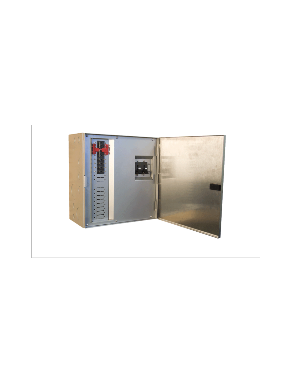
Figure 1 GS Load Center (GSLC) ................................................................................................................. 5
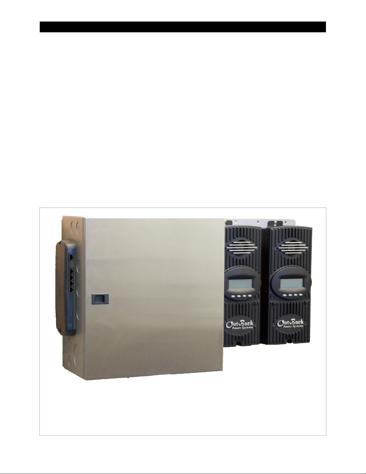
Figure 2 GS Load Center with Devices ..................................................................................................... 6
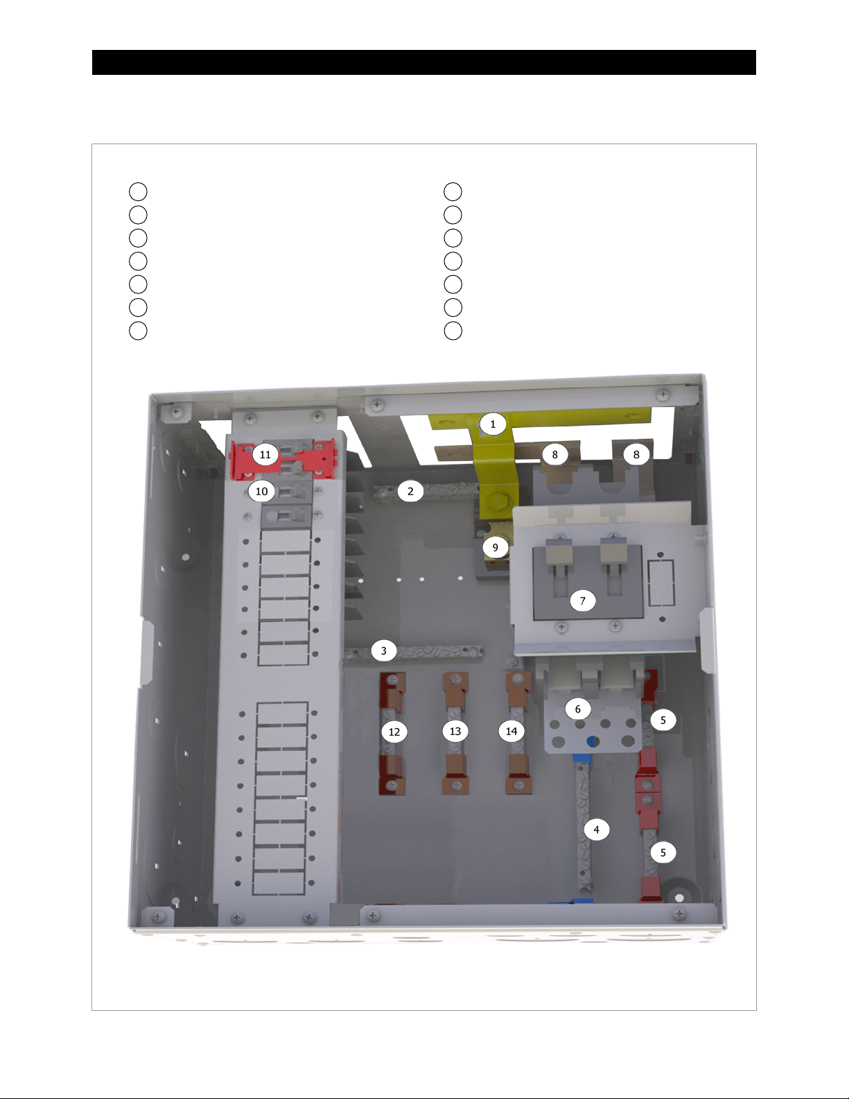
Figure 3 GSLC Components ......................................................................................................................... 7
Figure 4 GSLC175-120/240 Components ................................................................................................ 8
Figure 5 GSLC175-230 Components ......................................................................................................... 9
Figure 6 GSLC175-PV-120/240 Components ....................................................................................... 10
Figure 7 GSLC175-PV-230 Components ................................................................................................ 11
Figure 8 GSLC175PV1-120/240 Components ...................................................................................... 12
Figure 9 GSLC175PV1-230 Components ............................................................................................... 13
Figure 10 Dimensions ..................................................................................................................................... 15
Figure 11 Knockouts and Mounting Holesfor Devices ....................................................................... 16
Figure 12 GSLC – Additional Components .............................................................................................. 17
Figure 13 GSLC175-120/240 and GSLC175-230 – Additional Components ................................ 17
Figure 14 Removing the Top Cover from the GSLC ............................................................................. 18
Figure 15 Removing the Front Door from the GSLC ............................................................................ 18
Figure 16 Removing the Interior Cover from the GSLC ...................................................................... 19
Figure 17 DC Positive Cable Plate (FW-BBUS) ........................................................................................ 19
Figure 18 Assembling the DC Positive (+) Cable Plate ........................................................................ 20
Figure 19 Inverter Bus Bars ........................................................................................................................... 21
Figure 20 Inverter Main DC Disconnects .................................................................................................. 22
Figure 21 DC Shunts ....................................................................................................................................... 23
Figure 22 Circuit Breakers ............................................................................................................................. 24
Figure 23 Mounting the GSLC ..................................................................................................................... 25
Figure 24 Mounting the Charge Controller to the GSLC Enclosure ................................................ 27
Figure 25 Mounting the HUB Product to the GSLC Enclosure .......................................................... 28
Figure 26 Grounding....................................................................................................................................... 29
Figure 27 Removing Bonding Connections ............................................................................................ 30
Figure 28 Battery Connections .................................................................................................................... 32
2 900-0123-01-00 Rev C
Page 5

Table of Contents
Figure 29 FN-DC and Wiring Block ............................................................................................................. 33
Figure 30 Installing the FLEXnet DC .......................................................................................................... 33
Figure 31 PV Connections in the GSLC ..................................................................................................... 35
Figure 32 PV Connections in the FLEXmax Charge Controller ......................................................... 35
Figure 33 AC Terminal Bus Bars (split-phase) ......................................................................................... 37
Figure 34 Inverter AC Connections (split-phase) .................................................................................. 38
Figure 35 AC Terminal Bus Bars (single-phase) ...................................................................................... 39
Figure 36 Inverter AC Connections (single-phase) ............................................................................... 40
Figure 37 Maintenance Bypass Wiring (split-phase) ............................................................................ 41
Figure 38 Maintenance Bypass Wiring (single-phase)......................................................................... 42
Figure 39 Bypass Switches ............................................................................................................................ 43
Figure 40 OutBack Bypass (split-phase) ................................................................................................... 43
Figure 41 Bypass Switching for Multiple Inverters (split-phase) ...................................................... 44
Figure 42 Wiring Diagram – GSLC175-120/240 ..................................................................................... 45
Figure 43 Wiring Diagram – GSLC175-PV-120/240 with FNDC ........................................................ 46
Figure 44 Wiring Diagram – GSLC175PV1-120/240 with FNDC ....................................................... 47
Figure 45 Wiring Diagram – GSLC175-230 .............................................................................................. 48
Figure 46 Wiring Diagram – GSLC175-PV-230 with FNDC ................................................................. 49
Figure 47 Wiring Diagram – GSLC175PV1-230 with FNDC ................................................................ 50
900-0123-01-00 Rev C 3
Page 6

Table of Contents
This page intentionally left blank.
4 900-0123-01-00 Rev C
Page 7
Introduction
Welcome to OutBack Power Technologies
Thank you for purchasing a GS Load Center (GSLC) from OutBack Power Technologies. The GSLC is
part of an OutBack Grid/Hybrid™ system. It is a balance-of-systems enclosure intended to work with
Radian Series (GS) inverter/chargers, FLEXmax Charge Controllers, and an OutBack HUB
Communications Manager.
The removable front cover allows for opening from either side of the enclosure.
Figure 1 GS Load Center (GSLC)
The product is designed in the following configurations:
900-0123-01-00 Rev C 5
– GS Load Center for Radian Series. Recommended for custom-built systems. Recommended for use
GSLC
with multiple Radian inverters (one GSLC per inverter). Can be used with other inverter models. The term
“GSLC” is also used to refer generically to the product line.
Intended for any Radian model.
∼
GSLC175-120/240
inverter circuit breakers, dual AC inputs, and 120/240 Vac maintenance bypass assembly. Recommended for
systems which have a single Radian inverter and an AC source, but can be customized in other ways.
Intended for Radian models GS8048 and GS8048A.
∼
GSLC175-230
inverter circuit breakers, dual AC inputs, and 230 Vac maintenance bypass assembly. Recommended for
systems which have a single Radian inverter and an AC source, but can be customized in other ways.
Intended for Radian model GS7048E.
∼
– GS Load Center for AC applications (split-phase). Factory-prepared with dual 175 Adc
– GS Load Center for AC applications (single-phase). Factory-prepared with dual 175 Adc
Page 8
Introduction
The enclosure provides mounting holes for the HUB Communications Manager on the left.
Manual for more information.
GSLC175-PV-120/240
– GS Load Center for PV and AC applications (split-phase). Factory-prepared with
dual 175 Adc inverter circuit breakers, dual AC inputs, 120/240 Vac maintenance bypass assembly, PV GFDI,
and two PV array inputs, FLEXnet DC battery monitor and three shunts. Intended as a “plug-and-play”
solution for systems with a single inverter, two FLEXmax charge controllers, and battery monitoring.
Intended for Radian models GS8048 and GS8048A.
∼
GSLC175-PV-230
inverter circuit breakers, dual AC inputs, 230 Vac maintenance bypass assembly, PV GFDI, two PV array inputs, FLEXnet
DC battery monitor, and three shunts. Intended as a “plug-and-play” solution for systems with a single inverter, two
FLEXmax charge controllers, and battery monitoring.
Intended for Radian model GS7048E.
∼
GSLC175PV1-120/240
inverter circuit breaker, dual AC inputs, 120/240 Vac maintenance bypass assembly, PV GFDI, one PV array input,
FLEXnet DC battery monitor, and two shunts. Intended as a “plug-and-play” solution for systems with a single inverter,
one FLEXmax charge controller, and battery monitoring.
Intended for Radian model GS4048A.
∼
GSLC175PV1-230
inverter circuit breakers, dual AC inputs, 230 Vac maintenance bypass assembly, PV GFDI, one PV array input, FLEXnet DC
battery monitor, and two shunts. Intended as a “plug-and-play” solution for systems with a single inverter, one FLEXmax
charge controller, and battery monitoring.
Intended for Radian model GS3548E.
– GS Load Center for PV and AC applications (single-phase). Factory-prepared with dual 175 Adc
— GS Load Center for PV and AC applications (split-phase). Factory-prepared with one 175 Adc
— GS Load Center for PV and AC applications (single-phase). Factory-prepared with one 175 Adc
On the right, the enclosure has mounting holes for brackets to mount up to two FLEXmax charge controllers.
NOTE: OutBack FLEXmax Extreme charge controllers do not mount directly to the GSLC and do not require
additional mounting brackets. They are mounted beside the inverter or the GSLC. See the Radian Series Installation
Figure 2 GS Load Center with Devices
6 900-0123-01-00 Rev C
Page 9

Introduction
GSLC – Components
Inverter Negative (–) DC Bus Bars
NOTE: The installed Neutral TBB has white insulators
Legend
Negative (–) Terminal Bus Bar (TBB-WHITE)
Ground TBB (TBB-GROUND)
Neutral TBB (TBB-WHITE)
PV Positive (+) TBB (TBB-RED)
Shunt (FW-SHUNT500)
(TBB-WHITE). A set of blue insulators (TBB -BLUE) is included
in the kit for locations where blue is standard.
The DC Positive (+) Bus Plate (FW-BBUS) and the other
inverter positive (+) DC bus bars are also included in the kit.
900-0123-01-00 Rev C 7
Figure 3 GSLC Components
Page 10

Introduction
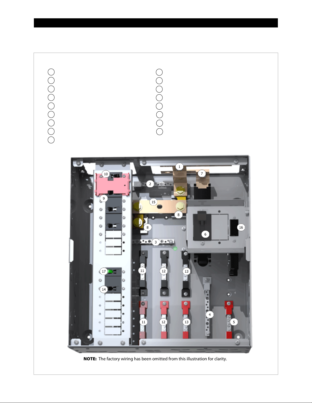
GSLC175-120/240 – Components
Inverter Negative (–) DC Bus Bar
Inverter Positive (+) DC Bus Bar
Legend
12
11
1
2
3 4 5 6 7
8
9
101413
NOTE: The factory wiring has been omitted from this illustration for clarity.
Negative (–) Terminal Bus Bar (TBB-WHITE)
Ground TBB (TBB-GROUND)
Neutral TBB (TBB-WHITE)
PV Positive (+) TBB (TBB-RED)
DC Positive (+) Cable Plate (FW-BBUS)
Main Inverter Disconnect(s) (PNL-175-DC)
Shunt (FW-SHUNT500)
AC Input Circuit Breakers (PNL-50D-AC-120/240V)
Maintenance Bypass Interlock
AC TBB (Inverter Output) L1, L2 (STBB-RED or BLACK)
AC TBB (Grid) L1, L2 (STBB-RED or BLACK)
AC TBB (Generator) L1, L2 (STBB-RED or BLACK)
8 900-0123-01-00 Rev C
Figure 4 GSLC175-120/240 Components
Page 11
Introduction
GSLC175-230 – Components
Inverter Negative (–) DC Bus Bar
Main Inverter Disconnect(s) (PNL-175-DC)
Inverter Positive (+) DC Bus Bar
Legend
12
11
1
2 3 4
5 6 7 8 9
10
14
13
NOTE:
Negative (–) Terminal Bus Bar (TBB-WHITE)
Ground TBB (TBB-GROUND)
Neutral TBB (TBB-BLUE)
PV Positive (+) TBB (TBB-RED)
DC Positive (+) Cable Plate (FW-BBUS)
Shunt (FW-SHUNT500)
AC Input Circuit Breakers (PNL-50-AC-230V)
Maintenance Bypass Interlock
AC TBB (Inverter Output) (TBB-BROWN)
AC TBB (Grid) (TBB-BROWN)
AC TBB (Generator) (TBB-BROWN)
900-0123-01-00 Rev C 9
The factory wiring has been omitted from this illustration for clarity.
Figure 5 GSLC175-230 Components
Page 12

Introduction
GSLC175-PV-120/240 – Components
Inverter Negative (–) DC Bus Bar
Legend
NOTE:
1 2 3
4
5 6 7
8
9
AC Input Circuit Breakers (PNL-50D-AC-120/240V)
12111014131615
18
17
Negative (–) Terminal Bus Bar (TBB-WHITE)
Ground TBB (TBB-GROUND)
Neutral TBB (TBB-WHITE)
PV Positive (+) TBB (TBB-RED)
DC Positive (+) Cable Plate (FW-BBUS)
Main Inverter Disconnect(s) (PNL-175-DC)
Inverter Positive (+) DC Bus Bar
Shunt (FW-SHUNT500)
Maintenance Bypass Interlock
AC TBB (Inverter Output) L1, L2 (STBB-RED or BLACK)
AC TBB (Grid) L1, L2 (STBB-RED or BLACK)
AC TBB (Generator) L1, L2 (STBB-RED or BLACK)
PV Input Disconnects (PNL-80-DC)
Shunt Bus (GS-SBUS)
Battery Monitor (FN-DC)
PV Ground Fault Detector/Interrupter
(PNL-GFDI-80D)
Figure 6 GSLC175-PV-120/240 Components
10 900-0123-01-00 Rev C
The factory wiring has been omitted from this illustration for clarity.
Page 13
Introduction
GSLC175-PV-230 – Components
Inverter Negative (–) DC Bus Bar
Legend
NOTE:
1 2 3 4 5
6 7 8
9
AC Input Circuit Breakers (PNL-50-AC-230V)
(PNL-GFDI-80D)
121110
141316
15
18
17
Negative (–) Terminal Bus Bar (TBB-WHITE)
Ground TBB (TBB-GROUND)
Neutral TBB (TBB-BLUE)
PV Positive (+) TBB (TBB-RED)
DC Positive (+) Cable Plate (FW-BBUS)
Main Inverter Disconnect(s) (PNL-175-DC)
Inverter Positive (+) DC Bus Bar
Shunt (FW-SHUNT500)
Maintenance Bypass Interlock
AC TBB (Inverter Output) (TBB-BROWN)
AC TBB (Grid) (TBB-BROWN)
AC TBB (Generator) (TBB-BROWN)
PV Input Disconnects (PNL-80-DC)
Shunt Bus (GS-SBUS)
Battery Monitor (FN-DC)
PV Ground Fault Detector/Interrupter
900-0123-01-00 Rev C 11
The factory wiring has been omitted from this illustration for clarity.
Figure 7 GSLC175-PV-230 Components
Page 14
Introduction
GSLC175PV1-120/240 – Components
Inverter Negative (–) DC Bus Bar
Legend
NOTE:
1 2 3
4
5 6 7
8
9
Maintenance Bypass Interlock
12111014131615
17
Negative (–) Terminal Bus Bar (TBB-WHITE)
Ground TBB (TBB-GROUND)
Neutral TBB (TBB-WHITE)
PV Positive (+) TBB (TBB-RED)
Main Inverter Disconnect (PNL-175-DC)
Inverter Positive (+) DC Bus Bar
Shunt (FW-SHUNT500)
AC Input Circuit Breakers (PNL-50D-AC-120/240V)
AC TBB (Inverter Output) L1, L2 (STBB-RED or BLACK)
AC TBB (Grid) L1, L2 (STBB-RED or BLACK)
AC TBB (Generator) L1, L2 (STBB-RED or BLACK)
PV Input Disconnect (PNL-80-DC)
Shunt Bus (GS-SBUS)
Battery Monitor (FN-DC)
PV Ground Fault Detector/Interrupter
(PNL-GFDI-80)
12 900-0123-01-00 Rev C
The factory wiring has been omitted from this illustration for clarity.
Figure 8 GSLC175PV1-120/240 Components
Page 15

Introduction
GSLC175PV1-230 – Components
Inverter Negative (–) DC Bus Bar
Legend
NOTE:
1 2 3
4
5 6 7
8
9
Maintenance Bypass Interlock
12111014131615
17
Negative (–) Terminal Bus Bar (TBB-WHITE)
Ground TBB (TBB-GROUND)
Neutral TBB (TBB-WHITE)
PV Positive (+) TBB (TBB-RED)
Main Inverter Disconnect (PNL-175-DC)
Inverter Positive (+) DC Bus Bar
Shunt (FW-SHUNT500)
AC Input Circuit Breakers (PNL-50-AC-230V)
AC TBB (Inverter Output) (TBB-BROWN)
AC TBB (Grid) (TBB-BROWN)
AC TBB (Generator) (TBB-BROWN)
PV Input Disconnect (PNL-80-DC)
Shunt Bus (GS-SBUS)
Battery Monitor (FN-DC)
PV Ground Fault Detector/Interrupter
(PNL-GFDI-80D)
900-0123-01-00 Rev C 13
The factory wiring has been omitted from this illustration for clarity.
Figure 9 GSLC175PV1-230 Components
Page 16

Introduction
This page intentionally left blank.
14 900-0123-01-00 Rev C
Page 17
Planning
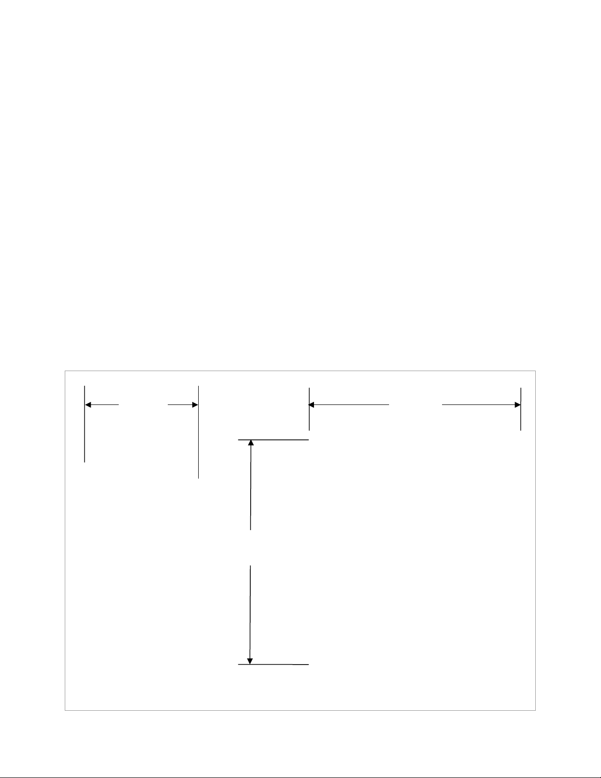
8½" (21.6 cm) deep
Side View
17"
high
16" (40.6 cm) wide
Front View
Tools Required
Open-ended wrenches (9/16" and13 mm)
Wire cutters/strippers
Torque wrenches
Assorted insulated screwdrivers
Digital Voltmeter (DVM) or regular voltmeter
Materials Required
Conductors for wiring
Conduits
Location/Environmental Requirements
Indoor mount only
(43.2 cm)
Figure 10 Dimensions
900-0123-01-00 Rev C 15
Page 18
Planning
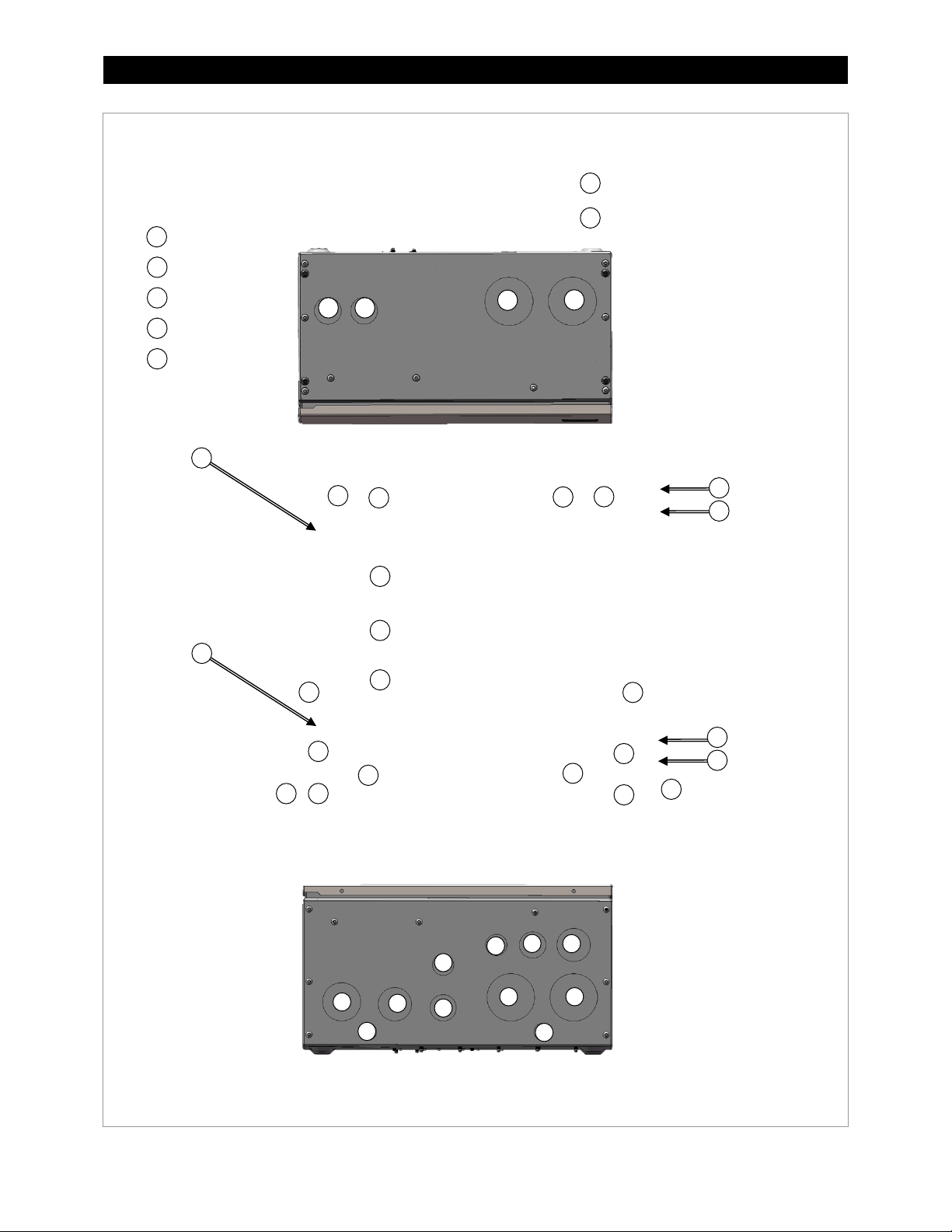
Legend
Mounting holes for FW-CCB
and FW-CCB2 brackets
2” or 63 mm
1¼” or 40 mm
½” or 20 mm
1½” or 50 mm
1” or 32 mm
1
2 3 4
5
Top View
1
1
4 4 7
8
Cable Knockouts
Mounting holes for HUB product
Side View
4
4 7 4
Side View
4
4
8 8 4 4 1 5 7
4
4
1 4 4 5 1
8 8 1
Bottom View
4 4 1 1 2 3 3
4
3 5 5
(U.S. Trade Size or Metric Trade Size)
16 900-0123-01-00 Rev C
Figure 11 Knockouts and Mounting Holesfor Devices
Page 19

Installation
The following components are sold separately
The following components are sold separately for the GSLC:
Hardware Options
The seven versions of the GSLC come with different components already installed.
, the “basic” or “empty” version, requires almost all components to be installed if they are needed.
GSLC
Instructions for this product begin on page 19.
GSLC175-120/240
and GS7048E. They have hardware for Radian inverter AC and DC connections. Battery monitoring or PV
capability must be installed as needed. Installation for these items begins with the DC shunts on page 23.
GSLC175-PV-120/240
GS8048A, and GS7048E. They have all options already present and need only to have external wiring and
devices added. Users with either of these versions can skip to the wiring section on page 29.
GSLC175PV1-120/240
and GS3548E. They have all options already present and need only to have external wiring and devices
added. Users with either of these versions can skip to the wiring section on page 29.
and
GSLC175-230
and
and
GSLC175-PV-230
GSLC175PV1-230
are the “inverter only” versions for Radian models GS8048, GS8048A,
are the “fully-loaded” versions for Radian models GS8048,
are the “fully-loaded” versions for Radian models GS4048A
Additional AC and DC circuit breakers are available for installation on all models.
The following pages describe the installation of individual items, including the removal of the GSLC
covers. Page 19 lists the hardware requirements for these items.
Instructions for Radian inverter mounting (along with other devices) begin on page 25.
Instructions for installing the FLEXnet DC battery monitor begin on page 33.
Instructions for installing the AC input-output bypass (IOB) assembly begin on page 42.
Inverter Main Disconnects (required for inverter installations)
AC Maintenance Bypass Assembly
AC Terminal Bus Bars (TBB)
PV Ground Fault Detector-Interrupter (GFDI)
FLEXnet DC Battery Monitor (FN-DC); see page 32
Additional DC shunts and GS-SBUS
PV Disconnect 80-amp circuit breaker (PNL-80-DC)
Figure 12 GSLC – Additional Components
for the GSLC175-120/240 and GSLC175-230:
PV Ground Fault Detector-Interrupter (GFDI)
FLEXnet DC Battery Monitor (FN-DC);
see page 32
Additional DC shunts and GS-SBUS
PV Disconnect 80-amp circuit breaker
(PNL-80-DC)
Figure 13 GSLC175-120/240 and GSLC175-230 – Additional Components
900-0123-01-00 Rev C 17
Page 20

Installation
Remove Top Cover
To Remove the Top Cover:
Enclosure with
Top Removed
Lift up to remove.
To Remove the Front Door:
Open to 90 degrees
1. Remove the four screws; one in each corner.
2. Lift the top off the enclosure.
Figure 14 Removing the Top Cover from the GSLC
Remove Front Door
1. Open the door to about 90 degrees.
2. Lift the hinges out of the slots at the
inside edge.
18 900-0123-01-00 Rev C
(shown partly open)
Figure 15 Removing the Front Door from the GSLC
Page 21

Assembly
Remove Interior Cover
Item
Terminal/Bolt Size
Torque Requirements
To Remove the Interior Cover:
Remove (x3)
Remove (x3)
Interior
Cover
Top Holes
Bottom Holes
0.5" (12.7 mm)
0.31" (8 mm)
0.4" (10 mm)
NOTE: The DC Positive (+) Cable
cannot be used with these models.
In order to make any wiring connections or to install components, the interior cover must be removed
to expose the interior of the enclosure. (This cover is sometimes called the “dead front.”)
1. Remove the three screws along the top of the enclosure
(with one star washer).
2. Remove the three screws along the bottom of the
enclosure (with one star washer).
3. Lift the front cover off the enclosure.
Figure 16 Removing the Interior Cover from the GSLC
Installing the Internal Hardware
Table 1 Size and Torque Requirements for Circuit Breakers and Bus Bars
Inverter Positive (+) Bus Bars M8 60 in-lb (6.8 Nm)
Shunt Bolts 3/8" 60 in-lb (6.8 Nm)
DC Positive (+) Cable Plate Top Holes (x3) 60 in-lb (6.8 Nm)
Bottom Holes (x7) 50 in-lb (5.7 Nm)
Circuit Breaker Studs M8 20 in-lb (2.3 Nm)
1/4" 35 in-lb (4.0 Nm)
5/16" 50 in-lb (5.7 Nm)
3/8" 225 in-lb (25.5 Nm)
900-0123-01-00 Rev C 19
Plate (FW-BBUS) is not included
with model GSLC175PV1-120/240
or model GSLC175PV1-230. It
Figure 17 DC Positive Cable Plate (FW-BBUS)
Page 22

Installation
Assembling DC Positive (+) Cable Plate (Bus Bar)
The bottom of each DC disconnect
: These instructions are not used with model GSLCPV1-120/240 and models GSLC175PV1-230.
NOTE
If using either of these models, proceed to page 21 or the next appropriate instruction.
(circuit breaker) is bolted to a metal
plate (bus bar) which receives the
inverter’s positive (+) battery cables.
To assemble the DC Positive Plate:
1. Remove the nuts and other hardware
(washer, lock washer, hex nut) from the
bottom terminal in the back of each DC
disconnect.
2. Place the two DC disconnects side
by side.
3. Orient the DC positive plate so that the
three largest holes are at the top. These
holes have a diameter of 0.50" (1.3 cm).
Insert the studs on each disconnect
through the first and third holes.
4. Replace the disconnect hardware
(washer, lock washer, hex nut). Tighten
the nuts to the values shown in Table 1
on page 19. The plate will hold the two
circuit breakers together as a set.
20 900-0123-01-00 Rev C
Figure 18 Assembling the DC Positive (+) Cable Plate
Page 23

Assembly
Installing Inverter Positive Bus Bars
A
B
To assemble the Inverter Positive (+) Bus Bars:
B
A
Top Bar
A
The GSLC parts kit contains two bus bars, A and B, which attach
to the tops of the DC disconnects. These bus bars make the
connections with the Radian inverter’s positive DC terminals.
Although they have similar shapes, the bus bars are not
interchangeable.
:
NOTE
model GSLC175PV1-230. When these models are in use, begin
the instructions with step 2.
1. Attach bus bar B to the top terminal of the
DC disconnect on the right, using the stud and
hardware on the back of the DC disconnect.
Tighten the nuts to the values shown in
Table 1 on page 19.
is not included with model GSLC175PV1-120/240 or
B
3. Mount bus bar A and the top bar to the top
terminal of the DC disconnect on the left.
Tighten to the value shown in Table 1 on page 19.
900-0123-01-00 Rev C 21
2. The GSLC’s hardware kit contains a top bar which attaches
to bus bar A. Attach these two bars together using a 5/16"
flat washer, a 5/16" lock washer, and an M8 nut (included in
hardware kit). Tighten to the value shown in
page 19.
Figure 19 Inverter Bus Bars
Table 1 on
Page 24

Installation
Installing Inverter Main DC Disconnects
To mount the inverter main DC disconnects:
in Table 1 on page 19.
These instructions assume that the GSLC has not yet been mounted to the Radian
Premounted bracket
Negative Top Bar
1. If the negative top bar is installed, loosen or remove it.
2. Slide the disconnect assembly through the opening in the
top of the GSLC and place it behind the premounted
bracket. Center the disconnect assembly so that the raised
area around the switch protrudes through the bracket. It
may be necessary to hold the assembly in place by hand.
3. Take the mounting screws provided with the circuit
breaker and insert them from the outside into the GSLC
bracket.
4. Tighten until secure, but do not over-tighten.
5. Reattach the negative top bar. Tighten to the value shown
inverter and that the top is open. If the GSLC’s top is closed or inaccessible, remove the
premounted bracket. Attach the disconnect assembly to it. Finally, re-install the bracket.
Figure 20 Inverter Main DC Disconnects
22 900-0123-01-00 Rev C
Page 25

Assembly
Installing DC Shunts
A single 500 Adc/50 mV shunt is included
Mounting Holes for
Pre-installed Shunt
Additional Shunt Placement
with the GSLC. Up to two more shunts
can be installed as needed. These shunts
are used in conjunction with the FLEXnet
DC battery monitor. See page
more instructions on wiring.
To mount DC Shunts:
1. Four mounting holes are located to the
lower left of the first shunt. Center each
shunt across one pair of mounting holes.
These should line up with the mounting
holes built into each shunt.
2. Using the screws included with the shunt,
attach each shunt to the GSLC enclosure.
3. Tighten the screws until secure, but do
not over-tighten.
31 for
Additional Shunts
NOTE: The GS-SBUS can be purchased
and installed to connect the
three shunts together. See
Figure 30 on page 33.
Figure 21 DC Shunts
900-0123-01-00 Rev C 23
Page 26

Installation
Installing PV and AC Circuit Breakers and GFDI
To mount circuit breakers:
NOTES
1. It may be necessary to remove the knockout
from the location where the circuit breaker is
to be placed to make room for the circuit
breaker to be installed. Be sure to remove
any debris that may occur from removing the
knockout.
2. Place each circuit breaker behind the
premounted rail. Center the device so that
the raised area around the switch protrudes
through the bracket. It may be necessary to
hold the device in place by hand.
2. When the circuit breaker is in place, insert the
screws included with each breaker through
the holes in the mounting rail.
3. Tighten the screws until secure, but do not
over-tighten.
Although there are no specific designations, the upper end of the mounting rail is generally used for AC
A PV ground-fault device may be required. The OutBack GFDI is pre-installed on some models. With other
Some installations may require an AC maintenance bypass. This is referred to as the Input-Output Bypass
24 900-0123-01-00 Rev C
devices (including the maintenance bypass). The lower end is generally used for DC devices, including the
GFDI. The preassembled GSLC models follow this convention.
models it can be purchased separately for manual installation. (See page 17.) The GFDI mounts the same
way as other circuit breakers. Once mounted, see page 34 and the GFDI manual for wiring instructions.
(Note that the GFCI usually requires multiple rail slots.)
or IOB. The bypass comes prewired for a single Radian inverter in some GSLC versions. It can also be
purchased separately. See page 37 and the GS-IOB manual for mounting and wiring instructions.
Figure 22 Circuit Breakers
Page 27

Assembly
Mounting on the Inverter
IMPORTANT:
strengthen the wall surface if required.
To mount the GSLC to the Radian inverter:
Bottom Screws
Mounting Feet
Holes (x4)
14"
12.5"
Continued on the next page....
Keyhole Slots
Keyhole Slots
The Radian inverter and GSLC are intended for indoor use only. Ensure that the
mounting surface is strong enough to support the full weight of the Radian
inverter/charger and the GSLC. Use a minimum 3/4" (19 mm) sheet of plywood to
1. Install the Radian inverter on the mounting bracket.
Remove knockouts from the bottom of the Radian inverter
if necessary and install bushings.
2. Back out bottom screw(s) approximately 1/4" (0.6 cm) to
3/16" (0.5 cm).
3. Remove the front and interior covers from the GSLC if
necessary (as described on page 18).
4. Align the GSLC along the bottom of the inverter and slide
the bottom screws into the keyhole slots.
5. Hanging the GSLC from the screws and holding it flush
against the bottom of the inverter, mark the spots for the
holes for the mounting feet. These are located in the rear
of the GSLC and are marked below.
6. If using wall anchors (included): Remove the GSLC. Using a
3/8" (10 mm) drill bit, drill leader holes for the hardware to
be used to secure the GSLC to the surface. Install the wall
anchors. If mounting on a solid surface like plywood, this
step can be skipped.
900-0123-01-00 Rev C 25
(35.6 cm)
Figure 23 Mounting the GSLC
Page 28

Installation
7. Realign the GSLC along the bottom of the inverter and slide the mounting screws into the keyhole slots.
Bottom Screws
Keyhole Slots
Keyhole Slots
...continued from the previous page.
8. Secure the enclosure to the mounting surface using all four mounting feet holes.
9. Using the bolts provided on the Radian inverter’s battery terminals, connect the terminals to the GSLC’s
inverter bus bars. Tighten to the value shown in Table 1 on page 19. For more information on the Radian
terminals, see the Radian Series Inverter/Charger Installation Manual.)
10. Leave the door and interior cover removed until all components have been installed and all wiring is
complete.
Figure 23 Mounting the GSLC (continued)
26 900-0123-01-00 Rev C
Page 29

Assembly
To mount the FLEXmax Charge
Dual Charge
(FW-CCB2)
4. Secure to the bottom bracket.
NOTE: This illustration shows only brackets for a
FW-CCB and FW-CCB2 are similar.
Mounting FLEXmax Charge Controller
The GSLC enclosure accommodates up to two FLEXmax charge controllers and a HUB
Communications Manager.
: The following instructions are for the FLEXmax 60 or FLEXmax 80 only. The FLEXmax Extreme
NOTE
charge controller connects directly to the wall and does not need additional brackets.
controller to the side of the GSLC
enclosure:
1. Align the brackets to the
mounting holes and secure the
brackets to the sides of the
enclosure with the hardware
provided with the brackets.
2. Note the location of knockouts on
both the charge controller and the
GSLC. (See page 16.) The holes
will align when the brackets are
used. Remove knockouts if
necessary and insert bushings.
3. Align the charge controller with
the center hole on each bracket
and secure with the hardware
provided with the brackets.
single charge controller (FW-CCB). Dual
charge controller brackets (FW-CCB2) are also
available. The installation instructions for
Controller Bracket
Figure 24 Mounting the Charge Controller to the GSLC Enclosure
900-0123-01-00 Rev C 27
Page 30

Installation
To mount the HUB Communications Manager to the side of the GSLC enclosure:
Mounting
Screw
Mounting
Screw
Mounting the HUB Communications Manager
The GSLC provides mounting holes to support a HUB Communications Manager.
1. Locate the mounting holes on the side of the GSLC enclosure as shown in Figure 11 on page 16.
2. Remove the knockouts and add bushings.
3. Align the HUB (vertically) over the mounting holes with the HUB product’s ports facing forward.
4. Insert the mounting screws from the outside into the GSLC enclosure. The mounting screws are provided
with the HUB product.
5. Tighten until secure, but do not over-tighten.
6. Install CAT5 cabling as needed.
7. Install the protective shield for the HUB product.
Figure 25 Mounting the HUB Product to the GSLC Enclosure
28 900-0123-01-00 Rev C
Page 31

Wiring
Wiring
WARNING: Shock Hazard
WARNING: Shock Hazard
IMPORTANT:
The GSLC’s grounding terminal bus bar ( TBB), which is
Ground TBB
Table 2 Terminal Bus Bar (TBB) Wire Size and Torque Requirements
Conductor Size Torque Requirements
AWG mm² In-lb Nm
#14 – #10 2.5 – 4 20 2.3
#8 6 – 10 25 2.8
#6– #3 16 – 25 35 4.0
#2 35 40 4.5
#1 – 1/0 50 50 5.7
Grounding
The unit must be connected to a permanent wiring system that is grounded
Make sure that no more than one bond is present in the AC system at any time.
For safety, the neutral and ground conductors should be mechanically bonded.
Some generators have a neutral-ground bond. When establishing a single bond
For all installations, the negative (–) battery conductor should be bonded to the
grounding system at only one point.
ground bond.
can provide the bond. See page 30.
Most OutBack products are not designed for use in a positive-grounded system. If it is
necessary to build a positive-grounded system with OutBack products, contact OutBack
Technical Support at
online forum at
discussed extensively.
according to the IEC 60364 TN standard.
Some codes require the bond to be made at the main panel only.
The GS Load Center (GSLC) is equipped with a neutral-ground bond. If bonding is
required to be in another location, the bond in the GSLC may need to be removed.
elsewhere, it may be necessary to check for a generator bond.
The GSLC comes equipped with a negative-
This bond may need to be disconnected. If the OutBack GFDI is present, it
+1.360.618.4363
www.outbackpower.com/forum/
before proceeding. Additionally, consult the
, where this subject has been
bonded to the GSLC chassis, is located to the lower left of
the main inverter disconnect. It accepts conductor sizes
from 1/0 to #14 AWG (50 mm down to 2.5 mm).
This TBB accepts ground connections from the Radian
inverter, FLEXmax charge controllers, the OutBack GFDI, the
Grounding Electrode Conductor (GEC) or external earth
ground, and other equipment.
See the Radian Series Inverter/Charger Installation Manual for
recommendations on ground conductor sizing. Once the
size is determined, see Table
2 for required torque values.
900-0123-01-00 Rev C 29
Figure 26 Grounding
Page 32

Installation
Bonding
WARNING: Shock Hazard
with the OutBack GFDI do not have a bond between negative and ground.
The GSLC’s neutral bus bar is located in
To remove either of the bond connections:
The GSLC’s negative (–) bus bar is located
NOTES:
Screw
TBB
Mount
TBB
Mount
Neutral-Ground Bond
Negative-Ground Bond
Bottom of GSLC
Standoff
Standoff
Inverter
Negative (
Bus Bar
Top of GSLC
Screw
All GSLC models are equipped with a mechanical bond between AC
neutral
and ground.
All models that do not include the GFDI are also equipped with a mechanical bond between DC
negative
and ground. These can be useful in stand-alone systems where no other bond is provided.
If other bonds are present, or if the GFDI is installed later, the GSLC bonds need to be removed.
If the GFDI is manually installed (see page 24 and the GFDI manual), the negative-ground
bond on the GSLC must be removed. This must also be done if any other PV ground-fault
device is present that establishes its own negative-ground bond. GSLC models purchased
the lower right portion of the GSLC.
The neutral-ground bond is established
at one end of the bar, near the base of
the GSLC.
near the top of the GSLC. It is attached to
the inverter negative (–) bus and its shunt.
–)
1. Using a Phillips screwdriver, remove the screw
shown above.
2. Remove the metal standoff beneath the bus
bar. The screw and bus bar provide the
mechanical bond to the chassis ground.
`
3. Rotate the TBB mount. Insert the bus bar into
the open end of the TBB mount so that the TBB
mount supports the bus bar. It may be
necessary to loosen the TBB mount screw
before rotating it.
4. Retighten the screw to secure the TBB mount.
Figure 27 Removing Bonding Connections
30 900-0123-01-00 Rev C
If the TBB is connected directly to
the enclosure by a screw, then the
bond is connected.
If the TBB is held by the TBB mount
and the TBB mount is secured to the
enclosure, the bond is disconnected.
The installed Neutral TBB has white
insulators. A second Neutral TBB with
blue insulators is included in the kit
for locations where blue is standard.
Page 33

Wiring
WARNING: Shock Hazard
before connecting any wires.
CAUTION: Fire Hazard
loss of contact area for current flow. This may allow dangerous levels of heat to build up.
GSLC175-PV-120/240
GSLC175-PV-230
GSLC175-120/240
DC Wiring
Ensure all circuit breakers or disconnect devices are turned off or disconnected
Never install extra washers or hardware between the mounting surface and the battery
cable lug. When installing multiple ring terminals or lugs, stack them on the mounting
surface so that the largest conductor is in direct contact. Smaller ring terminals should be
placed next in decreasing size order. Stacking the hardware in any order can result in a
Inverter Wiring
The DC disconnects are connected directly to the inverter using bus bars during the process of
mounting. See page 26 for more information.
Battery Wiring
Consult the Radian Series Inverter/Charger Installation Manual for appropriate recommendations for
cable number, sizing, and length. When using these recommendations, some models only require
one set of battery cables while other models require two sets of cables. (A single set of larger
conductors can be used if sized correctly.)
See Table 1 on page 19 for required torque values.
Ensure DC disconnects are turned to the OFF position and
DC sources are disconnected (unbolt the
all
battery end of the wires) before proceeding.
See the inverter’s installation manual for additional information on battery wiring.
Battery Positive (+) Cable
Follow the instructions below when connecting battery positive (+) cables to these models:
GSLC175-230
Connect the positive (+) cables to the DC positive (+) wiring plate. This plate is located directly
beneath the main inverter disconnects. It is intended for several ring lugs to be bolted to it.
The smaller holes have a diameter of 0.31" (8 mm).
∼
The larger holes have a diameter of 0.4" (10 mm).
∼
See item B in Figure 28 for an illustration of hardware installation order on the positive (+) plate.
Follow the instructions below when connecting battery positive (+) cables to these models:
GSLC175PV1-120/240
GSLC175PV1-230
Connect the positive (+) cable directly to the DC disconnect, which uses an M8 stud. See item A in
Figure 28 for an illustration of hardware installation order on the DC disconnect.
Follow the appropriate instructions when connecting to an “empty” GSLC which has been
assembled with similar features to one of the models above.
900-0123-01-00 Rev C 31
Page 34

Installation
Battery Negative (–) Cable
Shunt
Battery
Cable Lug
Flat Washer
Lock Washer
Shunt
Battery
Cable Lug
DC Disconnect
Flat Washer
Lock
Nut
Charge Controller
Battery
Monitor Ring
Shunt Plate
(if present)
3/8” Hex Bolt
Hardware Connection
to DC Disconnect
Flat Washer
Lock Washer
M8 -1.25 Hex Bolt
Flat
Nut
Hardware Connection
to DC Positive (+) Plate
Hardware Connection
to Shunt
DC positive (+)
cable plate (bus bar)
Battery
A
C
B
The battery negative (–) cables connect to the pre-installed shunt. This shunt is located to the upper
left of the main inverter disconnect. It is designed for several ring lugs to be bolted to it, with
openings of 3/8" (10 mm) diameter.
See item
in Figure 28 for an illustration of hardware installation order on the shunt. The shunt plate
C
(GS-SBUS) may or may not be present.
: Do not install hardware in a different order from the illustrations in Figure 28. In all cases the
NOTE
battery cable lug must be the first item installed. It must make solid contact with the surface.
Ring Terminal
Cable Lug
Figure 28 Battery Connections
32 900-0123-01-00 Rev C
Page 35

Wiring
Installing the FLEXnet DC
HUB port
Wiring block
To install the FN-DC :
When connecting sensing wires: The end of the shunt
FLEXnet DC
GS-SBUS
Shunt
screws
Shunt screws
Mounting
Mounting
The OutBack FLEXnet DC (FN-DC), or a similar battery monitor, may be added to the GSLC for
observing DC current flow and providing battery state-of-charge information.
`
Figure 29 FN-DC and Wiring Block
1. Assemble the FN-DC wiring as shown
in the manual for the FN-DC.
Attach sense wires to FN-DC wiring
block and plug it into the FN-DC.
Plug the CAT5 cable into the port
labeled HUB.
2. Connect FNDC wiring to the GSLC.
The positive (+) and negative (-)
battery voltage sense conductors
should connect directly to the
battery bank.
The shunt sensing wires should
connect to the screws on each
shunt. It may be necessary to
remove the GS-SBUS to reach
the screws.
3. Mount the FN-DC by inserting it into
the opening to the right of the
inverter disconnects. It may be
necessary to hold it in place.
4. Secure the FN-DC with mounting
screws above and below. Tighten
until secure, but do not over-tighten.
`
screws
screws
connected to the GS-SBUS is the negative (–) battery
connection and should be wired accordingly. The other
end of the shunt is the “device” or “load” end and should be
wired accordingly.
See the FLEXnet DC manual for more information on these
connections. See Figure 46 on page 49 for an example of
typical system wiring.
Figure 30 Installing the FLEXnet DC
900-0123-01-00 Rev C 33
Page 36

Installation
DC Devices
In addition to inverter or PV connections, other devices may be connected to the GSLC, such as DC
loads or sources. The wiring on these devices will vary with the application. In most cases the device
will have a separate circuit breaker which is mounted on the rail as shown on page 24. It will be wired
into the battery system using the existing bus bars or shunts. The number and location of these
connections will vary with the options or accessories installed.
PV and Charge Controller Wiring
When wiring the FLEXmax, FLEXmax Extreme, or another charge controller to the GSLC, a number of
elements are involved. These elements include the PV or RE source, the battery connections, the
disconnect circuit breaker, the PV ground-fault device, and the charge controller.
These instructions are written for a PV source which uses the OutBack FLEXmax (or FLEXmax Extreme)
charge controller and the GFDI. Other applications will be similar.
: In GSLC models designated as “PV”, many of the connections below are already provided. The
NOTE
only connections necessary are those for external wiring to the charge controller.
To make PV and charge controller connections:
1. Connect the PV positive wire to the GSLC’s PV positive (+) TBB (see Figure 31).
2. Connect the PV negative wire to the charge controller’s PV negative (–) terminal (see Figure 32).
3. Install a wire from the PV TBB to the PV disconnect circuit breaker (see Figure 31).
4. Install a wire from the PV disconnect to the charge controller’s PV positive (+) terminal.
5. Install a wire from the GSLC’s DC positive (+) cable plate to one pole of the GFDI.
6. Install a wire from the GFDI to the charge controller’s positive (+) battery terminal.
7. Install a wire from the charge controller’s negative (–) battery terminal to the GSLC’s negative TBB.
If the FLEXnet DC or another battery monitor is in use, this wire should connect to the shunt which
monitors that charge controller.
8. Repeat all steps for a second charge controller, if necessary.
NOTES:
Each TBB accepts conductors from 1/0 AWG (70 mm
for required torque values.
For other GSLC required torque values (such as shunts and circuit breakers), see Table 1 on page 19.
For torque values, wire sizes, and other information concerning the FLEXmax charge controller, see the
FLEXmax Series Charge Controllers Owner’s Manual.
For more information on specific wiring of the GFDI, see the GFDI manual.
A diagram that shows typical wiring for a PV system, including the FLEXnet DC, GFDI, and other elements of
the system, is shown on page 49.
A fully-assembled GSLC diagram with the elements mentioned above (as well as the AC system) is shown on
page 49.
2
) to #14 AWG (2.5 mm2) in size. See Table 2 on page 29
34 900-0123-01-00 Rev C
Page 37

Wiring
PV Positive (+) TBB
DC Positive (+) cable
plate (bus bar)
Shunt
PV Disconnect
Negative TBB
GFDI
BAT–
BAT+
PV Negative (–)
Battery Negative (–)
PV Positive (+)
Battery Positive (+)
PV+
PV–
`
Figure 31 PV Connections in the GSLC
`
Figure 32 PV Connections in the FLEXmax Charge Controller
900-0123-01-00 Rev C 35
Page 38

Installation
NOTES:
36 900-0123-01-00 Rev C
Page 39

Wiring
AC Wiring
WARNING: Shock Hazard
before wiring.
AC Output
Grid
Generator
Neutral
To make the external AC connections to the
1 2 3 4 5 6 7
Ensure all circuit breakers or disconnect devices are turned off or disconnected before
wiring. Make certain the inverter and other active devices are turned off or disabled
Split-Phase Wiring
The GSLC can have multiple terminal bus bars for multiple AC connections. Because the Radian
inverter possesses two sets of AC input connections and one set of output connections, up to three
TBB sets are available. Each set of bus bars are paired in red and black, for the 120/240 Vac
connections required by the Radian inverter.
The TBB set on the left is generally used for the inverter’s AC output connections. The central TBB set
is for utility grid connections and the right TBB set is for a generator. The preassembled GSLC models
follow this convention.
Each TBB accepts conductors from 1/0 (70 mm
required torque values.
If steps are inappropriate for a given system (such as instructions for a generator when none is
present), they can be ignored.
2
) to #14 AWG (2.5 mm2). See Table 2 on page 29 for
split-phase GSLC:
1. Connect the L1 wire from the AC load panel
to black TBB 1 (AC OUT - HOT LEG 1).
Connect the L2 wire from the AC load panel
to red TBB 2 (AC OUT - HOT LEG 2).
2. Connect the neutral wire from the AC load
panel to neutral TBB
3. Connect the L1 wire from the utility grid
panel (if present) to black TBB
(GRID IN - HOT LEG 1). Connect the L2 wire
from the utility grid panel to red TBB 5
(GRID IN - HOT LEG 2).
4. Connect the neutral wire from the utility
grid panel (if present) to neutral TBB 3.
5. Connect the L1 wire from the generator
(if present) to black TBB
LEG 1). Connect the L2 wire from the
generator to red TBB
6. Connect the neutral wire from the generator
(if present) to neutral TBB
NOTE: Remove the neutral-ground bond if
necessary. See page 30.
3.
4
6 (GEN IN - HOT
(GEN IN - HOT LEG 2).
7
3.
900-0123-01-00 Rev C 37
Figure 33 AC Terminal Bus Bars (split-phase)
Page 40

Installation
Bypass Assembly
To make the connections to the Radian inverter:
GRID
GEN
AC Output
Disconnects
8 2 3
4
5
6 7 1
Bypass switching can be used when the inverter is shut down for maintenance. This topic is discussed
more beginning on page 42. The GSLC can be equipped with the GS-IOB-120/240VAC bypass
assembly. The instructions on this page are for making external connections to the bypass assembly
after installation. (The installation wiring for the GS-IOB-120/240VAC is described on page 41.)
If no bypass assembly is used, connections should be made directly to each TBB from the circuit
breakers for the inverter, AC sources, and loads. These connections are designated in Figure 33.
Wiring diagrams for an assembled 120/240 Vac system are shown beginning on page 45.
1. Designate the top AC circuit breaker as the
inverter AC output disconnect. Install a wire from
the black AC output TBB (as shown in Figure 33. to
the disconnect marked by
2. Install a wire from the red AC output TBB to the
disconnect marked by
3. Install wires on the left side of the disconnect as
marked by
appropriate L1 and L2 output terminals on
the Radian inverter.
4. Designate the third AC circuit breaker from the
top as the disconnect for one AC source (GRID or
GEN). Install a wire from the black source circuit
TBB (as shown in Figure 33) to the disconnect
marked by 5.
5. Install a wire from the red source circuit TBB to
the disconnect marked by
6. Install wires on the right side of the disconnect
as marked by
appropriate L1 and L2 input terminals on the
Radian inverter (the terminals labeled either GRID
or GEN).
7. If a second AC source is present, repeat steps 4
through 6 using the bottom circuit breaker.
3 and 4. Connect these wires to the
7 and 8. Connect these wires to the
2.
1.
6.
8. Install a wire on the inverter’s NEU terminal and
connect it to the GSLC’s neutral TBB (as shown in
Figure 33). Only one neutral connection is required.
and
inputs
Figure 34 Inverter AC Connections (split-phase)
38 900-0123-01-00 Rev C
Page 41

Wiring
Single-Phase Wiring
AC Output
Grid
Generator
Neutral
To make external AC connections to the
1
2 3 4
The GSLC allows multiple terminal bus bars (TBB) for multiple AC connections. Because the Radian
inverter possesses two sets of AC input connections and one set of output connections, three terminal
bus bars are available for hot connections, as well as one neutral bus bar. The hot bus bars use brown
insulators in 230 Vac models. The neutral bus bar uses blue insulators in 230 vac models.
The TBB on the left is generally used for the inverter’s AC output connections. The central TBB is for
utility grid connections and the right TBB is for a generator. The preassembled GSLC models follow
this convention.
2
Each TBB accepts conductors from 70 mm
for required torque values.
If steps are inappropriate for a given system (such as instructions for a generator when none is
present), they can be ignored.
single-phase GSLC:
1. Connect the hot wire from the AC load
panel to brown TBB 1 (AC Output).
(1/0 AWG) to 2.5 mm2 (#14 AWG). See Table 2 on page 29
2. Connect the neutral wire from the AC
load panel to neutral TBB
3. Connect the hot wire from the utility grid
panel (if present) to brown TBB 3 (Grid).
4. Connect the neutral wire from the utility
grid panel (if present) to neutral TBB 2.
5. Connect the hot wire from the generator
(if present) to brown TBB 4 (Generator).
6. Connect the neutral wire from the
generator (if present) to neutral TBB 2.
NOTE: Remove the neutral-ground bond
if necessary. See page 30.
The neutral insulator in Figure 35 is in the
position which opens the bond.
2.
Figure 35 AC Terminal Bus Bars (single-phase)
900-0123-01-00 Rev C 39
Page 42

Installation
Bypass Assembly
To make the connections to the
GRID and GEN inputs
AC output
Disconnects
2
4
1
3
Bypass switching can be used when the inverter is shut down for maintenance. This topic is discussed
more beginning on page 42. The GSLC can be equipped with the GS-IOB-230VAC bypass assembly.
The instructions on this page are for making external connections to the bypass assembly after
installation. (The installation wiring for the GS-IOB-230VAC is described on page 42.)
If the GSLC has no bypass assembly, connections should be made directly to each TBB from the circuit
breakers for the inverter, AC sources, and loads. These connections are designated in Figure 35.
Wiring diagrams for an assembled 230 Vac system are shown beginning on page 48.
Radian inverter:
1. Designate the topmost AC circuit breaker
as the inverter AC output disconnect.
Install a wire from the AC output circuit TBB
(as shown in Figure 35) to that disconnect
as marked by 1.
2. Install a wire on the left side of the
disconnect as marked by
wire to the appropriate output terminals on
the Radian inverter.
3. Designate the third AC circuit breaker as
the disconnect for one AC source (GRID or
GEN). Install a wire from the TBB of the
appropriate source circuit (as shown in
Figure 35) to the left side of that disconnect
as marked by
3.
2. Connect the
4. Install a wire on the right side of the source
disconnect as marked by
wire to the appropriate input terminal on
the Radian inverter (the terminal labeled
either GRID or GEN).
5. If a second AC source is present, repeat
steps 3 and 4.
6. Install a wire on the inverter’s NEU terminal
and connect it to the GSLC’s neutral TBB
(as shown in Figure 35). Only one neutral
connection is required.
4. Connect the
40 900-0123-01-00 Rev C
Figure 36 Inverter AC Connections (single-phase)
Page 43

Wiring
Wiring the AC Bypass Assembly
To wire the GS-IOB-120/240VAC
Output
Inverter
1 2 4
3
5
6
AC
8
7
All models other than the “empty” GSLC are equipped with a maintenance bypass assembly. As
needed, the GSLC can be equipped with a bypass assembly using the GS-IOB-120/240VAC or GS-IOB230VAC accessory kit as appropriate. The accessory kit should be installed according to its own
instructions. Once installed, it can be wired by following the steps shown in Figure 37 or Figure 38 .
The operation of the bypass assembly is discussed on page 42. A series of GSLC diagrams with the
bypass wiring (as well as the rest of both the AC and DC systems) are shown beginning on page 48.
These drawings show the utility grid circuit connected to the bypass assembly. This is the method
used during factory installation. However, either the grid or the generator circuit may be used. A
prewired assembly may be changed. Remove the first source from the bypass assembly and then wire
the second according to the instructions. Connect the first source directly to the terminals as shown in
the drawings beginning on page 45.
: Only one AC source may be bypassed with this assembly, even if two sources are present.
NOTE
WARNING: Shock Hazard or Equipment Damage
Bypassing multiple sources will usually connect the sources to each other, which may
damage one or both sources. It can otherwise result in power being routed to
inappropriate places.
The internal GSLC bypass assembly cannot be used if multiple inverters are in use.
See page 42.
after installation:
1. On the disconnect for the AC
source that will be used during
bypass, install a wire from the
upper pole as shown by
Connect it to the upper pole of
the inverter bypass switch as
shown by
2. From the same disconnect,
install a wire on the lower pole
as shown by
the lower pole of the inverter
bypass switch as shown by 4.
3. On the right side of the inverter
bypass switch, install a wire on
the lower pole as shown by
Connect it to the right side of
the lower pole on the output
switch
between the upper poles of
each switch as shown by
8.
and
1.
2.
3. Connect it to
5.
6. Install a second wire
7
Bypass
Source
Figure 37 Maintenance Bypass Wiring (split-phase)
900-0123-01-00 Rev C 41
Page 44

Installation
To wire the GS-IOB-230VAC
after installation:
Output
Inverter Bypass
AC Source
1 2 3
4
1. On the disconnect for the AC
source that will be used during
bypass, install a wire from the
left side as shown by
Connect it to the input bypass
switch as shown by 2.
2. Install a wire on the right side of
the input bypass switch as
shown by
right side of the output switch
as shown by 4.
3. Connect it to the
Figure 38 Maintenance Bypass Wiring (single-phase)
1.
Multiple-Inverter Installations (Stacking Inverters)
When multiple Radian inverters are stacked for additional power, the basic wiring is repeated for each
inverter. However, several factors need to be considered.
One GSLC is required for each Radian inverter. A single GSLC cannot be sized to handle the requisite current
for multiple Radian inverters.
If more than two Radian inverters are installed, it is recommended to install a separate distribution panel to
distribute incoming power to each GSLC individually. It may be advisable to install separate AC distribution
panels to distribute input and output power to each GSLC.
The GSLC maintenance bypass assemblies cannot be used when more than one Radian inverter is stacked.
See the next section.
Bypass Switches
Inverter systems are often equipped with maintenance bypass switches or interlocks. If the inverter
system ever needs to be shut down or removed, its AC sources and loads must be disconnected. A
bypass device allows the AC source to “bypass” the inverter and deliver power directly to the loads.
This can minimize disruption to the system and it avoids the need for extensive rewiring.
WARNING: Shock Hazard or Equipment Damage
Bypassing multiple sources will usually connect the sources to each other, which may
damage one or both sources. It can otherwise result in power being routed to
inappropriate places.
The bypass assembly does not disconnect the inverter’s AC input. Even with the
inverter bypassed, any AC input source may be a shock hazard unless disconnected.
42 900-0123-01-00 Rev C
Page 45

Wiring
In Figure 39, when Switch 1 is on (normal operation), the inverter’s output sends power to the loads.
AC Loads
Switch 1
Switch 2
Inverter Output
Bypass AC Source
Switch 1 and Switch 2 are prevented
The inverter may use an AC
AC Source
AC Loads
GSLC Bypass
Disconnected
Input Wiring
Output Wiring
Switch 2 is off, preventing the inverter from sending power back to the AC source (backfeeding).
When Switch 2 is on (bypass operation), the AC source sends power directly to the loads. Switch 1 is
off, removing the inverter’s output from the loads. This also prevents the AC source from backfeeding
the inverter. With the inverter removed from the circuit, maintenance can be performed as necessary.
source which powers the
inverter’s output. The bypass
assembly does not disconnect
the inverter’s input.
from being on at the same time by the
Mechanical Interlock. Although both
switches can be off, only one can be on.
In OutBack bypass assemblies, circuit
breakers are used instead of standard
switches.
Figure 39 Bypass Switches
The GSLC can be ordered with bypass circuit breakers for this purpose, or it has a bypass option (the
GS-IOB-120/240VAC or GS-IOB-230VAC) which can be installed.
Radian
Inverter
Figure 40 OutBack Bypass (split-phase)
In a new system with multiple Radian inverters, the basic GSLC should be used in conjunction with an
external assembly of this kind, as shown in Figure 41. The GS-IOB kits should not be installed, or if
previously installed, should be removed and all wires disconnected.
OutBack does not offer a solution for bypassing multiple inverters. However, electrical suppliers offer
both manual and automatic double-pole, double-throw bypass switches in a range of sizes and
options. These are highly recommended for systems larger than a single inverter.
IMPORTANT:
If multiple Radian inverters are stacked in a single system, then these devices
cannot be used. The bypass function must be simultaneous for all inverters. The
GSLC bypass kits operate independently, not simultaneously.
900-0123-01-00 Rev C 43
WARNING: Shock Hazard or Equipment Damage
Using independent bypass devices on multiple inverters can result in power being routed
to inappropriate places. This could lead to an electric shock or to equipment damage.
Page 46

Installation
AC Source
AC Loads
Output Wiring
Inactive Radian Inverters
Input Wiring
GSLC Bypass Devices
External Bypass Device
111
1
Figure 41 Bypass Switching for Multiple Inverters (split-phase)
(must be removed if
installed previously)
44 900-0123-01-00 Rev C
Page 47

Wiring
Wiring Diagrams
This GSLC model has a neutral-ground bond
and a negative-ground bond which are added
during construction. They are not depicted
here. The bonds can be removed if necessary.
See page
30.
900-0123-01-00 Rev C 45
Figure 42 Wiring Diagram – GSLC175-120/240
Page 48

Installation
This GSLC model has a neutral-ground bond which is added during construction. It is not depicted
here. The bond can be removed if necessary. See page 28.
Figure 43 Wiring Diagram – GSLC175-PV-120/240 with FNDC
46 900-0123-01-00 Rev C
Page 49

Wiring
This GSLC model has a neutral-ground bond which is added during construction. It is not depicted
here. The bond can be removed if necessary. See page 28.
Figure 44 Wiring Diagram – GSLC175PV1-120/240 with FNDC
900-0123-01-00 Rev C 47
Page 50

Installation
This GSLC model has a neutral-ground bond
and a negative-ground bond which are added
during construction. They are not depicted
here. The bonds can be removed if necessary.
See page 28.
48 900-0123-01-00 Rev C
Figure 45 Wiring Diagram – GSLC175-230
Page 51

Wiring
This GSLC model has a neutral-ground bond which is added during construction. It is not depicted
here. The bond can be removed if necessary. See page 28.
Figure 46 Wiring Diagram – GSLC175-PV-230 with FNDC
900-0123-01-00 Rev C 49
Page 52

Installation
This GSLC model has a neutral-ground bond which is added during construction. It is not depicted
here. The bond can be removed if necessary. See page 28.
Figure 47 Wiring Diagram – GSLC175PV1-230 with FNDC
50 900-0123-01-00 Rev C
Page 53

Electrical Specifications
Specification
Measurement
Maximum Input Voltage
600 Volts
Maximum Input Current
500 Amps
Operating Frequency Range
50/60 Hz to DC
Specification
Measurement
Dimensions (H x W x D)
17" x 16" x 8.5" (43.2 cm x 40.6 cm x 21.6 cm)
Shipping Dimensions (L x W x H)
23.25" x 20.5" x 13.25" (59.1 cm x 52.1 cm x 33.7 cm)
Weight
26 lb (11.8 kg) minimum — varies with options
Shipping Weight
34 lb (15.4 kg) minimum — varies with options
Enclosure Type
Indoor
Table 3 Electrical Specifications
Mechanical Specifications
Table 4 Mechanical Specifications
Specifications
Regulatory Specifications
UL 1741, 2
Power Systems
Canadian Electrical Code, Part I (CSA C22.2 No. 107.1-01 (R2006)
nd
Edition, Revised January 28, 2010, Static Inverter and Charge Controllers for Use in Photovoltaic
900-0123-01-00 Rev C 51
Page 54

Specifications
Definitions
Table 5 Terms and Definitions
Term
Definition
The following is a list of initials, terms, and definitions used in conjunction with this product.
AC Alternating Current; refers to voltage produced by the inverter, utility grid, or generator
AUX One of several auxiliary outputs on the GS inverter/charger.
CSA Canadian Standards Association; establishes Canadian national standards and the Canadian
Electrical Code, including C22.1 and C22.2
DC Direct Current; refers to voltage produced by the batteries or renewable source
DVM Digital Voltmeter
FNDC OutBack battery monitor; used to measure battery state of charge
GFDI Ground Fault Detector Interrupter; a safety device for PV systems
PV Photovoltaic
RE Renewable Energy
UL Underwriters Laboratories; refers to a set of safety standards governing electrical products
52 900-0123-01-00 Rev C
Page 55

A
AC Bypass Assembly ..................................... 38, 40, 41, 42
AC Circuit Breakers ............................................................. 24
AC Terminal Bus Bars ........................................................ 37
AC Wiring ........................................................................ 37, 45
120/240 Vac ............................................................. 37, 45
Additional Components .................................................. 17
AUX .......................................................................................... 52
B
Bonding .................................................................................. 30
Brackets .................................................................................. 16
Bypass Switches .................................................................. 42
Bypass Switching for Multiple Inverters .................... 44
Index
F
Features .................................................................................... 5
FLEXmax Charge Controller ................................ 6, 27, 34
FLEXnet DC ............................................................................ 33
Front Door ............................................................................. 18
Functions .................................................................................. 5
FW-CCB ................................................................................... 16
FW-CCB2 ................................................................................. 16
G
GFDI .......................................................................................... 24
Grid Interface Protection ................................
Grounding ............................................................................. 29
.................. 51
C
Charge Controller .................................................... 6, 27, 34
Components
Basic GSLC .......................................................................... 7
GSLC175-120/240 ......................................... 8, 9, 10, 11
GSLC175PV1-120/240 ................................................. 12
GSLC175PV1-230 .......................................................... 13
Conduit Sizes ........................................................................ 16
CSA ........................................................................................... 51
D
DC Devices ............................................................................ 34
DC Disconnects ................................................................... 22
DC Positive Cable Plate (Bus Bar)
Assembling ..................................................................... 20
DC Shunts .............................................................................. 23
DC Wiring ............................................................................... 31
Dead Front ............................................................................ 19
Definitions ............................................................................. 52
Dimensions ........................................................................... 15
DVM ......................................................................................... 52
E
Environmental Requirements........................................ 15
H
HUB Communications Manager ................................... 28
I
Input Modes ............................................................................ 5
Interior Cover ........................................................................ 19
Internal Hardware ............................................................... 19
Inverter Main Disconnects ............................................... 22
Inverter Positive Bus Bars ................................................. 21
K
Knockouts .............................................................................. 16
M
Materials Required.............................................................. 15
Model Descriptions ....................................................... 5, 17
Modes ........................................................................................ 5
Mounting
Charge Controller.......................................................... 27
GSLC ................................................................................... 25
HUB ..................................................................................... 28
Inverter .............................................................................. 25
Mounting Holes ................................................................... 16
900-0123-01-00 Rev C 53
Page 56

Index
N
Negative-Ground Bonding ............................................. 30
Neutral-Ground Bonding ................................................ 30
O
Optional Hardware ............................................................ 17
P
Positive Bus Hardware ............................................... 20, 21
PV Circuit Breakers ............................................................. 24
PV Wiring ............................................................................... 34
R
Regulatory ............................................................................. 51
S
Specifications
Electrical ........................................................................... 51
Mechanical ...................................................................... 51
Regulatory ....................................................................... 51
Stacking Inverters ............................................................... 42
T
Terminal .................................................................................. 19
Terms and Definitions ....................................................... 52
Tools Required ..................................................................... 15
Top Cover ............................................................................... 18
Torque Requirements ....................................................... 19
U
UL .............................................................................................. 51
W
Wire Size and Torque Requirements ........................... 29
Wiring
120/240 Vac .............................................................. 37, 45
AC ................................................................................. 37, 45
Bonding ............................................................................ 30
Charge Controller.......................................................... 34
DC ........................................................................................ 31
FLEXnet DC ...................................................................... 33
Grounding ........................................................................ 29
PV ........................................................................................ 34
54 900-0123-01-00 Rev C
Page 57

This page intentionally left blank.
Page 58

This page intentionally left blank.
900-0123-01-00 Rev C
Page 59

This page intentionally left blank.
Page 60

Masters of the Off-Grid.™ First Choice for the New Grid.
Corporate Headquarters
+1.360.435.6030
European Office
+49.9122.79889.0
17825 – 59th Avenue N.E.
Suite B
Arlington, WA 98223 USA
900-0123-01-00 Rev C
Hansastrasse 8
D-91126
Schwabach, Germany
 Loading...