

Page 1
Radian Series Inverter/Charger
GS8048
Installation Manual
Page 2

Address:
Corporate Headquarters
Arlington, WA 98223 USA
European Office
Schwabach, Germany
Telephone:
+1.360.435.6030
+1.360.435.6019 (Fax)
+49.9122.79889.0
Email:
Support@outbackpower.com
Website:
http://www.outbackpower.com
About OutBack Power Technologies
OutBack Power Technologies is a leader in advanced energy conversion technology. OutBack products include
true sine wave inverter/chargers, maximum power point tracking charge controllers, and system communication
components, as well as circuit breakers, accessories, and assembled systems.
Contact Information
17825 – 59th Avenue N.E.
Suite B
+1.360.618.4363 (Technical Support)
Hansastrasse 8
D-91126
+49.9122.79889.21 (Fax)
Disclaimer
UNLESS SPECIFICALLY AGREED TO IN WRITING, OUTBACK POWER TECHNOLOGIES:
(a) MAKES NO WARRANTY AS TO THE ACCURACY, SUFFICIENCY OR SUITABILITY OF ANY TECHNICAL OR OTHER
INFORMATION PROVIDED IN ITS MANUALS OR OTHER DOCUMENTATION.
(b) ASSUMES NO RESPONSIBILITY OR LIABILITY FOR LOSS OR DAMAGE, WHETHER DIRECT, INDIRECT,
CONSEQUENTIAL OR INCIDENTAL, WHICH MIGHT ARISE OUT OF THE USE OF SUCH INFORMATION. THE USE OF
ANY SUCH INFORMATION WILL BE ENTIRELY AT THE USER’S RISK.
Warranty Summary
OutBack Power Technologies Inc. warrants that the products it manufactures will be free from defects in
materials and workmanship for a period of five (5) years subject to the conditions set forth in the warranty detail,
found in the Radian Series Inverter/Charger Operator’s Manual.
OutBack Power Technologies cannot be responsible for system failure, damages, or injury resulting from
improper installation of their products.
Notice of Copyright
Radian Series Inverter/Charger Installation Manual © 2011 by OutBack Power Technologies. All Rights Reserved.
Trademarks
OutBack Power and the OutBack Power logo are trademarks owned and used by OutBack Power Technologies,
Inc. The ALPHA logo and the phrase “member of the Alpha Group” are trademarks owned and used by Alpha
Technologies Inc. These trademarks may be registered in the United States and other countries.
Date and Revision
October 2013, Revision B
Part Number
900-0021-01-00 Rev B
Page 3
Important Safety Instructions
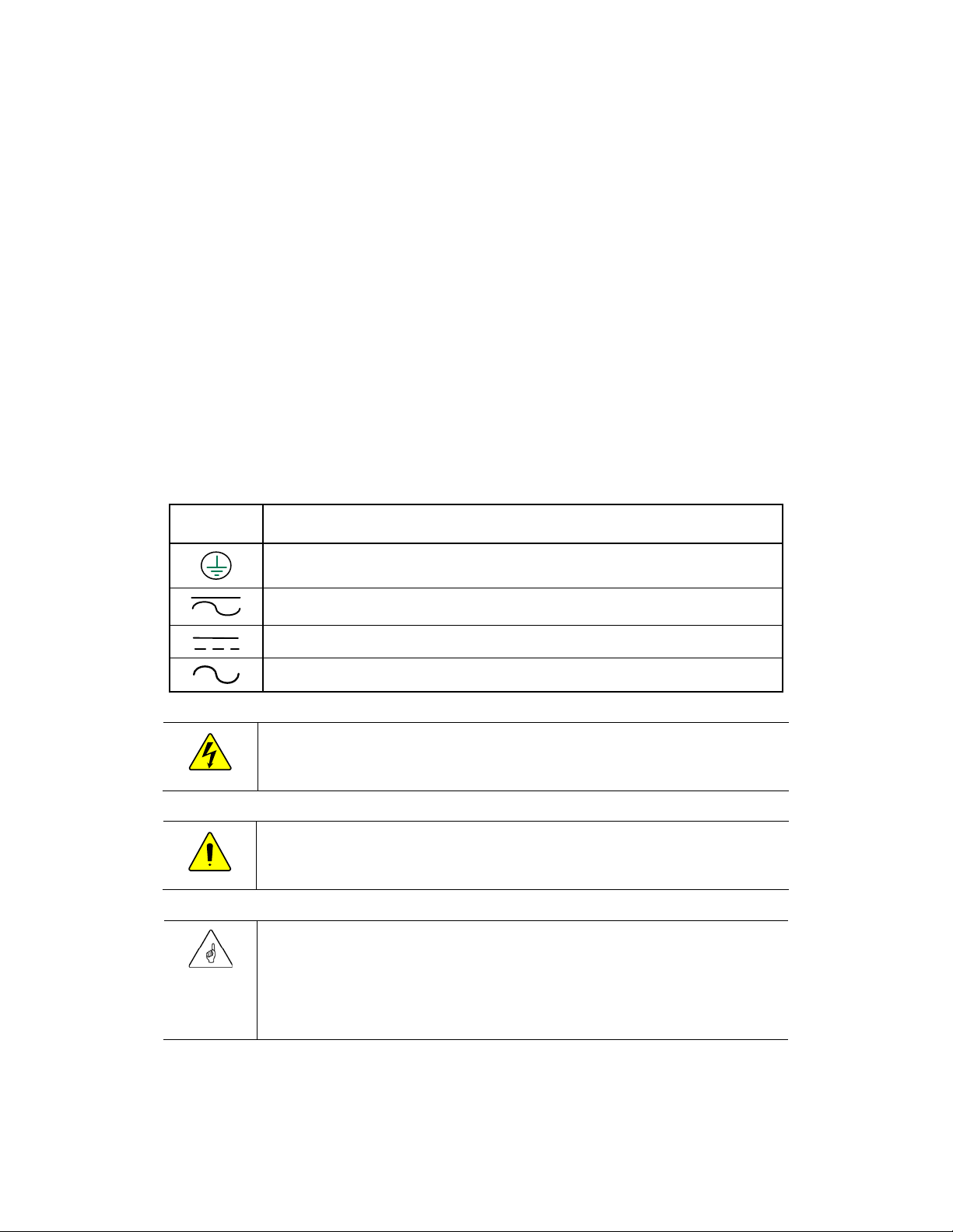
Symbol
Description
Ground
AC Current
DC Current
Sine Wave
WARNING: Hazard to Human Life
This type of notation indicates that the hazard could be harmful to human life.
CAUTION: Hazard to Equipment
This type of notation indicates that the hazard may cause damage to the equipment.
IMPORTANT:
equipment warranty.
READ AND SAVE THESE INSTRUCTIONS!
This manual contains important safety instructions for the Radian Series Inverter/Charger. Read all
instructions and cautionary markings on the inverter and on any accessories or additional equipment
included in the installation. Failure to adhere to these instructions could result in severe shock or
possible electrocution. Exercise extreme caution at all times to prevent accidents.
Audience
These instructions are for use by qualified personnel who meet all local and governmental code
requirements for licensing and training for the installation of electrical power systems with AC and DC
voltage up to 600 volts.
Symbols Used
This type of notation indicates that the information provided is important to
the installation, operation and/or maintenance of the equipment. Failure to
follow the recommendations in such a notation could result in voiding the
900-0021-01-00 Rev B 1
Page 4

Important Safety Instructions
Table 1 Terms and Definitions
Term
Definition
12V AUX
Auxiliary connection that supplies 12 Vdc to control external devices.
AC
Alternating Current; refers to voltage produced by the inverter, utility grid, or generator
AGS
Advanced Generator Start
CSA
Canadian Standards Association; establishes Canadian national standards and the
Canadian Electrical Code, including C22.1 and C22.2
DC
Direct Current; refers to voltage produced by the batteries or renewable source
DVM
Digital Voltmeter
ETL
Electrical Testing Laboratories; short for the company ETL Semko; refers to a certification
issued by ETL to OutBack products indicating that they meet certain UL standards
GFDI
Ground Fault Detector Interruptor; a safety device for PV systems
GND
Ground; a permanent conductive connection to earth for safety reasons; also known as
Chassis Ground, Protective Earth, PE, Grounding Electrode Conductor, and GEC
Grid-interactive,
grid-intertie, grid-tie
Utility grid power is available for use and the inverter is a model capable of returning
(selling) electricity back to the utility grid
GSLC
GS Load Center; the wiring box for the Radian (GS) inverter
HBX
High Battery Transfer; a function of the MATE3
HUB
A line of OutBack communications manager products
IEEE
Institute of Electrical and Electronics Engineers; refers to a series of standards and
practices for the testing of electrical products
LBCO
Low Battery Cut-Out; set point at which the inverter shuts down due to low voltage
MATE3
An OutBack system display, used for monitoring, programming and communicating
with the inverter
NEC
National Electric Code
NEU
AC Neutral; also known as Common
Off-grid
Utility grid power
is not
available for use
PV
Photovoltaic
RELAY AUX
Auxiliary connection that uses switch (relay) contacts to control external devices.
RTS
Remote Temperature Sensor; accessory that measures battery temperature for charging
Definitions
The following is a list of initials, terms, and definitions used with this product.
2 900-0021-01-00 Rev B
Page 5
Important Safety Instructions
Table 1 Terms and Definitions
Term
Definition
Split-phase
A type of utility electrical system with 2 “hot” lines that are 120 Vac with respect to
neutral and 240 Vac between the “hot” lines; common in North America
System display
Remote interface device (such as the MATE3), used for monitoring, programming and
communicating with the inverter; also called “remote system display”
UL
Underwriters Laboratories; refers to a set of safety standards governing electrical
products
Utility grid
The electrical service and infrastructure supported by the electrical or utility company;
also called “mains”, “utility service”, or “grid”
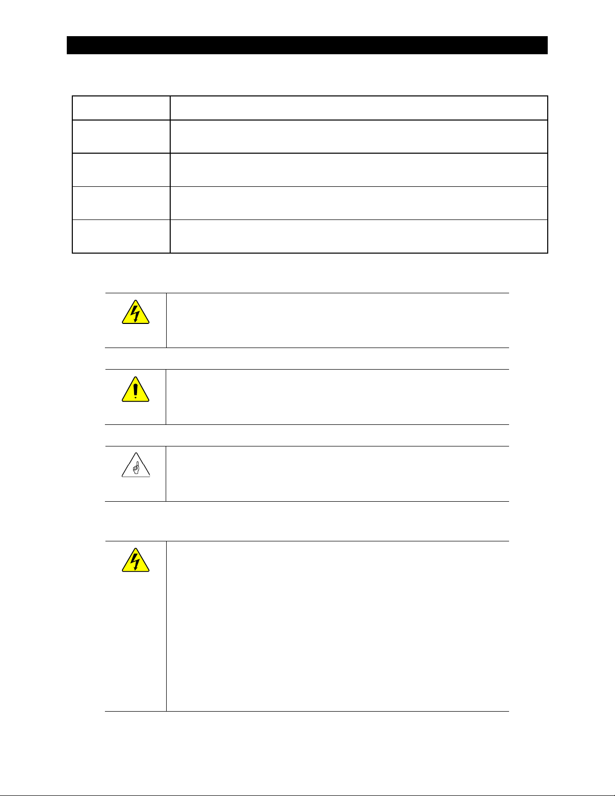
WARNING: Limitations on Use
equipment or devices.
CAUTION: Equipment Damage
Technologies or its authorized agents.
IMPORTANT:
the Warranty section for instructions on returning the equipment.
WARNING: Personal Injury
General Safety
This equipment is NOT intended for use with life support equipment or other medical
Personal Safety
Only use components or accessories recommended or sold by OutBack Power
Do not attempt to install this equipment if it appears to be damaged in any way. See
This equipment weighs in excess of 125
when lifting this equipment as prescribed by the Occupational Safety and Health
Association (OSHA) or other local codes.
Use standard safety equipment such as safety glasses, ear protection, steel-toed
safety boots, safety hard hats, etc., as prescribed by the Occupational Safety and
Health Association (or other local codes) when working on this equipment.
Use standard safety practices when working with electrical equipment (e.g., remove
all jewelry, use insulated tools, wear cotton clothing, etc.).
Never work alone when installing or servicing this equipment. Have someone
nearby that can assist if necessary.
57 kg). Use safe lifting techniques
lbs (
900-0021-01-00 Rev B 3
Page 6
Important Safety Instructions
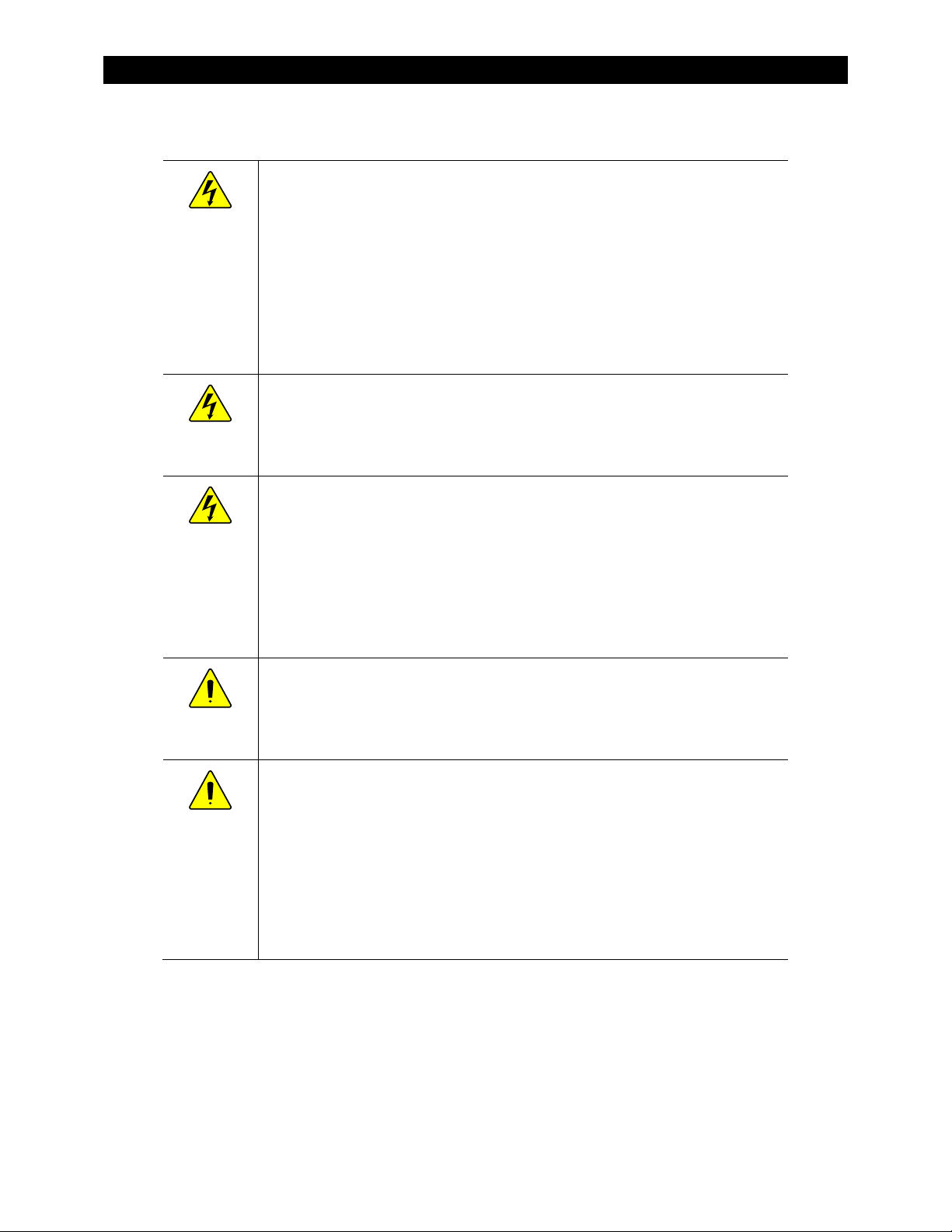
Inverter Safety
WARNING: Lethal Voltage
WARNING: Burn Hazard
to cool down before attempting to perform any maintenance.
WARNING: Fire Hazard
CAUTION: Equipment Damage
equipment and void the product warranty.
CAUTION: Equipment Damage
Review the system configuration to identify all possible sources of energy. Ensure
ALL sources of power are disconnected before performing any installation or
maintenance on this equipment. Confirm that the terminals are de-energized using
a validated voltmeter (rated for a minimum 1000 Vac and 1000 Vdc) to verify the deenergized condition.
Do not perform any servicing other than that specified in the installation
instructions unless qualified to do so, or have been instructed to do so by OutBack
Power Technologies Technical Support personnel.
Internal parts can become hot during operation. Do not remove the cover during
operation or touch any internal parts. Be sure to allow sufficient time for internal parts
Do not place combustible or flammable materials within 12 feet (3.7 m) of
the equipment.
This product contains relays with moving parts and is not ignition-protected.
Ensure AC, DC, and ground cable sizes conform to local codes. See pages 24
through 26 for minimum size requirements. Ensure all conductors are in good
condition. Do not operate the unit with damaged or substandard cabling.
When connecting cables from the inverter to the battery terminals, ensure the proper
polarity is observed. Connecting the cables incorrectly can damage or destroy the
Thoroughly inspect the equipment prior to energizing. Verify that no tools or
equipment have been inadvertently left behind.
Ensure clearance requirements are strictly enforced. Keep all vents clear of
obstructions that can prevent proper air flow around, or through, the unit.
Sensitive electronics inside the equipment can be destroyed by static electricity. Be
sure to discharge any static electricity before touching the equipment and wear
appropriate protective gear.
4 900-0021-01-00 Rev B
Page 7
Important Safety Instructions
WARNING: Explosion, Electrocution, or Fire Hazard
IMPORTANT:
Have a supply of either substance readily available if using these types of batteries.
Battery Safety
Use the battery types recommended by OutBack Power Technologies. Follow the
battery manufacturer’s recommendations for installation and maintenance.
Ensure the cables are properly sized. Failure to size the cables properly can result in
a fire hazard.
Ensure clearance requirements are strictly enforced around the batteries.
Ensure the area around the batteries is well ventilated and clean of debris.
Never smoke near, or allow a spark or flame near, the batteries.
Always use insulated tools. Avoid dropping tools onto batteries or other
electrical parts.
Keep plenty of fresh water and soap nearby in case battery acid contacts skin,
clothing, or eyes.
Wear complete eye and clothing protection when working with batteries. Avoid
touching bare skin or eyes while working near batteries.
If battery acid contacts skin or clothing, wash immediately with soap and water. If
acid enters the eye, immediately flood it with running cold water for at least
20 minutes and get medical attention as soon as possible.
Never charge a frozen battery.
Insulate batteries as appropriate against freezing temperatures. A discharged
battery will freeze more easily than a charged one.
If a battery must be removed, always remove the grounded terminal from the
battery first. Make sure all devices are de-energized or disconnected to avoid
causing a spark.
If a remote or automatic generator control system is used, disable the starting
circuit and/or disconnect the generator from its starting battery while performing
maintenance to prevent accidental starting.
Baking Soda neutralizes lead-acid battery electrolyte.
Vinegar neutralizes NiCad and NiFe battery electrolyte.
900-0021-01-00 Rev B 5
Page 8

Additional Information
Regulatory Specifications
See the Radian Series Inverter/Charger Operator’s Manual for all specifications and regulatory
information, including certifications.
Required Resources
This product is required to be installed according to pertinent safety codes and standards. If installed
in the United States, wiring practices must meet the requirements of the National Electrical Code
(NEC). If installed in Canada, wiring practices must meet the requirements of the Canadian
Electrical Code.
National Electrical Code (NEC)/NFPA 70, Current Edition
Canadian Electrical Code, C22.1, Current Edition
Additional Resources
The following are references which may be used when installing this equipment. Depending on the
nature of the installation, it may be highly recommended to consult any or all of these resources.
National Electrical Code (NEC)/NFPA 70 Handbook, Current Edition
UL 1741, Current Edition, Static Inverter and Charge Controllers for Use in Photovoltaic Power Systems
International Building Code (IBC), Current Edition
Photovoltaic Power Systems and the 2005 National Electrical Code: Suggested Practices
6 900-0021-01-00 Rev B
Page 9

Additional Information
IMPORTANT: Recycle Electronics and Batteries
provide additional information for recycling electronic products and batteries.
Recycling Information
Batteries are considered hazardous waste and must be recycled according to
local jurisdiction. Inverters and other electronics contain metals and plastics
that should also be recycled. The following web sites and phone numbers
Earth 911, USA
Web site: www.Earth911.com
Address: 14646 N. Kierland Blvd., Suite 100
Scottsdale, AZ 85254
Phone: +1.480.337.3025 (direct)
Environmental Protection Agency, USA
Web site: www.epa.gov/recyclecity/
Email: r9.recyclecity@epa.gov
Phone: +1.415.947.8000
(Monday –Friday 8:00 AM to 12:00 PM and 1:00 PM to 4:00 PM PST)
Keep America Beautiful, USA
Web site: www.kab.org/
Email: info@kab.org
Address: 1010 Washington Boulevard
Stamford, CT 06901
Phone: +1.203.659.3000 (Main number)
Fax: +1.203.659.3001
OurEarth.org, USA
There is a place on the website for contacting OurEarth.org using email. No direct email address
is provided.
Web site: http://www.ourearth.org
Address: P.O. Box 62133
Durham, NC 27715
Phone: +1.410.878.6485
National Institute of Recyclers, Mexico
Web site: http://www.inare.org.mx/
Email: a57841279@prodigy.net.mx, margarita@inare.org.mx
Phone: +1.55.57.85.9160
Fax: +1.55.57.84.1279
900-0021-01-00 Rev B 7
Page 10

Additional Information
Natural Resources Canada
Address: 580 Booth, Ottawa, ON K1A 0E8
Web site: http://www.nrcan-rncan.gc.ca/mms-smm/busi-indu/rec-rec-eng.htm
Phone: +1.613.995.0947
TTY: +1.613.996.4397
(Phone and TTY: Monday to Friday, 8:30 a.m. to 4:30 p.m. ET)
Office of Waste Management, Canada
Web site: http://www.portaec.net/library/recycling/recycling_in_canada.html
Address: Office of Waste Management
Conservation and Protection
Environment Canada
Ottawa, Ontaro K1A 0H3
Phone: +1.819.997.2800
EuroRecycle.net, Europe
The following website provides general information about recycling in Europe. It also provides a list of
companies and organizations that provide recycling information or assistance.
Web site: http://euro.recycle.net
E-mail: http://euro.recycle.net/cgi-bin/feedback1.cgi?w=27
(This is an online form providing a means to contact the owners of the website.)
8 900-0021-01-00 Rev B
Page 11

Table of Contents
Important Safety Instructions ........................................................................ 1
Audience ................................................................................................................................................................................. 1
Symbols Used ........................................................................................................................................................................ 1
Definitions ............................................................................................................................................................................... 2
General Safety ....................................................................................................................................................................... 3
Personal Safety ...................................................................................................................................................................... 3
Inverter Safety ....................................................................................................................................................................... 4
Battery Safety ......................................................................................................................................................................... 5
Regulatory Specifications .................................................................................................................................................. 6
Required Resources ............................................................................................................................................................. 6
Additional Resources .......................................................................................................................................................... 6
Recycling Information ........................................................................................................................................................ 7
Introduction ............................................................................................... 11
Welcome to OutBack Power Technologies .............................................................................................................. 11
Components and Accessories ...................................................................................................................................... 12
Planning .................................................................................................... 13
Applications ........................................................................................................................................................................ 13
Renewable Energy ............................................................................................................................................................ 14
Battery Bank ........................................................................................................................................................................ 14
Generator ............................................................................................................................................................................. 15
Maintenance Bypass Switching ................................................................................................................................... 16
Installation ................................................................................................. 17
Location and Environmental Requirements ............................................................................................................ 17
Dimensions .......................................................................................................................................................................... 17
Tools Required .................................................................................................................................................................... 18
Mounting .............................................................................................................................................................................. 18
Accessory Mounting .......................................................................................................................................................................... 20
Removing Front Cover .................................................................................................................................................... 21
Terminals and Ports .......................................................................................................................................................... 22
Grounding ............................................................................................................................................................................ 24
DC Wiring ............................................................................................................................................................................. 25
AC Wiring.............................................................................................................................................................................. 26
AC Sources ............................................................................................................................................................................................. 27
Accessory Wiring ............................................................................................................................................................... 28
AUX Wiring .......................................................................................................................................................................... 29
Generator Control) ............................................................................................................................................................................. 31
Single-Inverter AC Installations .................................................................................................................................... 34
Multiple-Inverter AC Installations (Stacking) ........................................................................................................... 35
Functional Test ................................................................................................................................................................... 38
Index ......................................................................................................... 39
900-0021-01-00 Rev B 9
Page 12

Table of Contents
List of Tables
Table 1 Terms and Definitions ................................................................................................................... 2
Table 2 Components and Accessories .................................................................................................. 12
Table 3 Ground Conductor Size and Torque Requirements .......................................................... 24
Table 4 DC Conductor Size and Torque Requirements ................................................................... 25
List of Figures
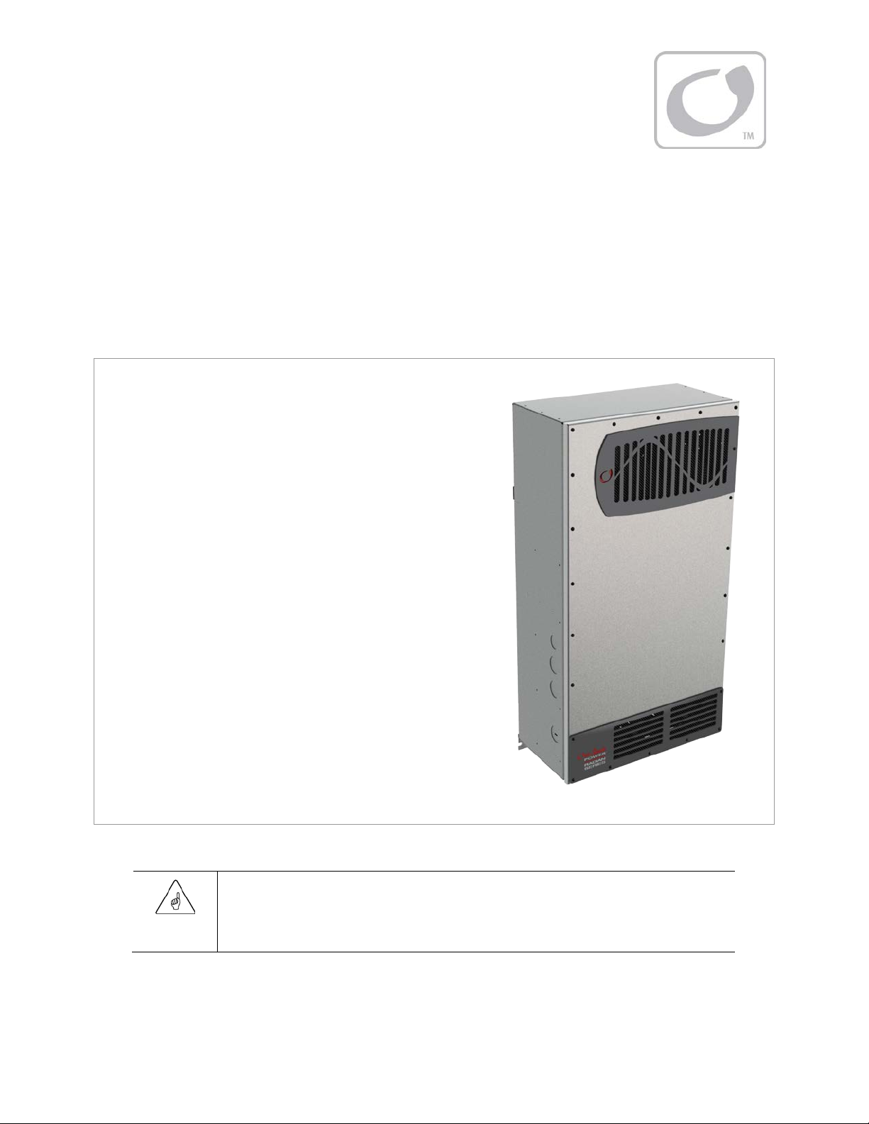
Figure 1 GS8048 Inverter/Charger ........................................................................................................... 11
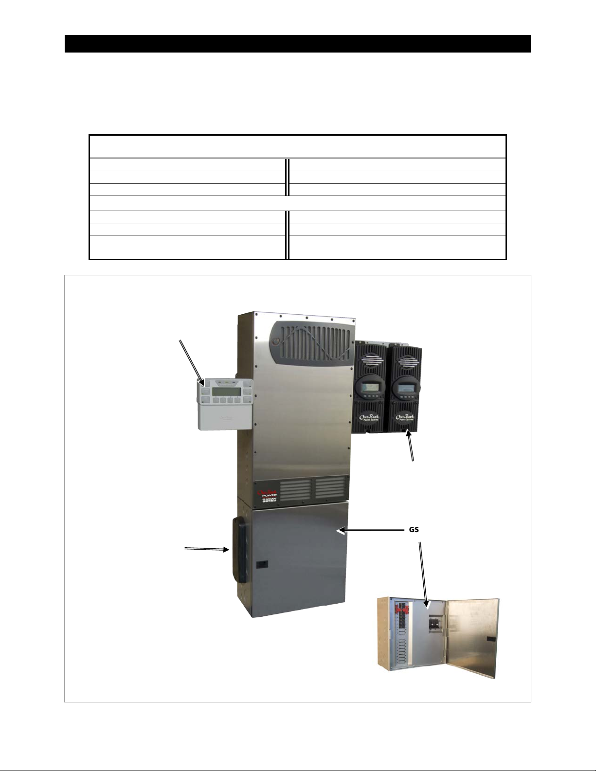
Figure 2 Radian Inverter and Accessories ............................................................................................. 12
Figure 3 Applications (Example) ............................................................................................................... 13
Figure 4 Bypass Switching .......................................................................................................................... 16
Figure 5 Bypass Switching for Multiple Inverters ............................................................................... 16
Figure 6 Dimensions ..................................................................................................................................... 17
Figure 7 Installing the Mounting Plate ................................................................................................... 18
Figure 8 Mounting the Inverter ................................................................................................................ 19
Figure 9 Mounting for System Components ........................................................................................ 20
Figure 10 Cover Screws .................................................................................................................................. 21
Figure 11 DC Terminals, Ribbon Cables, and Auxiliary Terminals ................................................... 22
Figure 12 AC Terminals, Ports, and Ground Bus .................................................................................... 23
Figure 13 Chassis Ground TBB ..................................................................................................................... 24
Figure 14 DC Cable Hardware (underside of inverter) ........................................................................ 25
Figure 15 AC Terminals .................................................................................................................................. 26
Figure 16 AC Sources ...................................................................................................................................... 27
Figure 17 Accessory Connections .............................................................................................................. 28
Figure 18 ON/OFF Jumper and Connections.......................................................................................... 28
Figure 19 AUX Connections for Vent Fan (Example)............................................................................ 29
Figure 20 AUX Connections for Diversion (Example) .......................................................................... 30
Figure 21 Two-Wire Generator Start (RELAY AUX)................................................................................ 31
Figure 22 Two-Wire Generator Start (12V AUX) ..................................................................................... 32
Figure 23 Three-Wire Generator Start (Example) .................................................................................. 33
Figure 24 Single-Inverter Wiring ................................................................................................................. 34
Figure 25 OutBack HUB4 and MATE3 ....................................................................................................... 35
Figure 26 Example of Parallel Stacking Arrangement (Three Inverters)........................................ 36
Figure 27 Parallel Wiring ................................................................................................................................ 37
10 900-0021-01-00 Rev B
Page 13
Introduction
IMPORTANT:
Controller. Use of these products is not supported with the Radian Series.
Mounts easily with supplied mounting plate.
Welcome to OutBack Power Technologies
Thank you for purchasing the OutBack Radian Series Inverter/Charger. This product offers a complete
power conversion system between batteries and AC power. It can provide backup power, sell power
back to the utility grid, or provide complete stand-alone off-grid service.
All terminals exit at the bottom of the inverter.
This allows the installer to use a single distribution
box. The GS Load Center (GSLC) is specifically
designed for this purpose and is sold separately.
Uses spring-based AC terminals instead of
screw-based terminals. This eliminates torque
requirements and periodic re-tightening.
Uses the MATE3 System Display and Controller
(sold separately) for user interface.
Features versatile mounting locations for the
MATE3, HUB, and FLEXmax products, as well as
the GSLC.
The venting on the cover allows mounting of
multiple Radian inverter/chargers side by side
with zero clearance required between them.
Up to 10 Radian Series Inverter/Chargers can be
stacked together.
This product is not compatible with the OutBack MATE or MATE2 System Display and
Figure 1 GS8048 Inverter/Charger
900-0021-01-00 Rev B 11
Page 14
Introduction
Radian Series Installation Manual
RTS (Remote Temperature Sensor)
Radian Series Operator’s Manual
Hardware Kit
Mounting Bracket
Optional Components for Attachment to Radian Inverter
MATE3 System Display and Controller
FLEXmax 60 or FLEXmax 80 Charge Controller
FW-MB3 (MATE3 bracket)
FW-CCB or FW-CCB2 (charge controller brackets)
GSLC, GSLC175-120/240, or GSLC-PV-120-/240
(GS Load Centers)
GSLC
MATE3
HUB
FLEXmax
Charge Controllers
Components and Accessories
Table 2 Components and Accessories
Included in Box
OutBack HUB4 or HUB10
12 900-0021-01-00 Rev B
Figure 2 Radian Inverter and Accessories
Page 15

Planning
Applications
The Radian Series Inverter/Charger is intended for both grid-interactive and off-grid applications.
These inverters are designed to use a battery bank to store energy. They can work in conjunction with
photovoltaic (PV) panels to harvest solar energy, as well as wind turbines and other renewable
sources. These sources charge the battery, which in turn is used by the inverter.
Figure 3 Applications (Example)
The Radian inverter has six modes of operation. Each mode has functions and priorities that are
intended for a designated application. Each of the Radian’s two AC inputs can be set to a different
operating mode, so that different applications can be supported.
: See the Radian Series Inverter/Charger Operator’s Manual for additional information on these
NOTE
modes, including the benefits of using each mode.
Generator
imperfect AC waveform. The Radian will charge from the generator even when the generator is undersized
or substandard.
Support
other limitations may require temporary assistance to run very large loads. The Radian adds inverter and
battery power to the AC source to ensure that the loads receive the power they require.
Grid Tied
batteries above a selected “target” voltage, the Radian inverter will send the excess energy to any loads. If
the loads do not use all the excess energy, then the Radian will return that energy to the utility grid.
UPS
power to the loads without any interruption during a transfer to, or from, the AC input. The speed of
900-0021-01-00 Rev B 13
: This mode is intended for a wide range of AC sources, including generators with a rough or
: This mode is intended for systems that use the utility grid or a generator. AC source size, wiring, or
: This mode is intended for grid-interactive systems. When renewable energy sources charge the
(Uninterruptible Power Supply): This mode is intended for systems whose main focus is to maintain
Page 16

Planning
response in this mode has been increased so that if the AC input power is disconnected or a scheduled
disconnect occurs the response time will be minimized.
Backup
the Radian inverter to power the loads unless utility power is lost. If utility grid power is lost, then the Radian
inverter will supply energy to the loads from the battery bank until the power is back online.
Minigrid
renewable energy production. The system will run off the renewable energy production until the battery
voltage falls to a specified low level. When this occurs, the Radian inverter will connect to the utility grid,
which will power the loads. The Radian inverter will disconnect from the utility grid when the batteries are
sufficiently recharged.
: This mode is intended for systems that have the utility grid available. This source will flow through
: This mode is intended for systems that have the utility grid as an input and a sizable amount of
Renewable Energy
The Radian Series Inverter/Charger cannot connect directly to photovoltaic arrays, wind turbines, or
other renewable sources. The batteries are the primary source of power. However, if these sources
are used to charge the batteries, the inverter can use their energy by drawing it from the batteries.
The renewable source is always treated as a battery charger, even if all of its power is used
immediately. The renewable source must have a charge controller or some way to prevent
overcharging. OutBack Power’s FLEXmax family of charge controllers can be used for this purpose, as
can other products.
The GSLC will receive the mechanical and electrical connections for up to two FLEXmax charge
controllers. It can receive the electrical connections for two FLEXmax Extreme charge controllers.
Battery Bank
When planning a battery bank, consider the following:
Cables:
will determine the placement of the battery bank. Other local codes or regulations may apply and may take
priority over OutBack recommendations.
Battery Type:
discharge. These include batteries for marine, golf-cart, and forklift applications. They also include gel-cell
batteries and absorbed glass-mat (AGM) batteries. OutBack Power recommends the use of batteries
designed specifically for renewable energy applications. Automotive batteries are strongly discouraged and
will have a short life if used in inverter applications. Nickel-based batteries are discouraged due to
limitations in the Radian charger. Lithium-based batteries and other advanced battery technologies may
require special considerations. Please contact OutBack Technical Support at
implementing advanced battery technologies.
The Radian inverter/charger is designed to work with a 48-volt battery bank. Before constructing a battery
bank, confirm the nominal voltage of individual batteries.
Bank Size:
expected loads and run time.
~ To prevent the inverter’s charger from overcharging, the minimum recommended battery bank size is
~ If other charging devices are present, the minimum bank size should be determined by adding the
Systems intended to bridge short-term outages can use smaller battery banks. In these cases, the bank can
be as low as 200 amp-hours per inverter. However, the charge rate must be decreased to half the inverter’s
maximum using the MATE3. (See the MATE3 manual.) One of the following conditions must also be true.
~ The system is equipped with a backup generator that is programmed for automatic start, or
Recommendations for battery cable size and length are shown on page 25. The maximum length
The Radian inverter/charger works best with lead-chemistry batteries intended for deep
+1.360.618.4363
In backup or off- grid applications, the battery bank size should be calculated based on
350 amp-hours for every Radian inverter/charger installed on the system.
inverter(s) charge rate to any other chargers and multiplying the result by five. Example: If the system’s
combined charge rate was 160 Adc, the minimum battery bank size should be 800 amp-hours.
before
14 900-0021-01-00 Rev B
Page 17

Planning
~ Typical grid loss is 30 minutes or less, or
IMPORTANT:
factory default settings, may cause the batteries to be undercharged or overcharged.
CAUTION: Hazard to Equipment
product warranty. (Sealed batteries may be an exception.)
~ The loads are less than 2 kW.
NOTE: If support time or load size are disproportionate to the bank size, they will cause inverter shutdown
due to low battery voltage after a short time. These conditions could be detrimental to the life of a small
battery bank. If this is true, the recommendations from the previous page apply instead.
Charger Settings and Maintenance:
code and is recommended in most cases for safety reasons. It may be necessary to use a fan to ventilate the
battery enclosure. (See the Operator’s Manual for vent fan applications.)
Batteries must be regularly maintained according to the instructions of the battery manufacturer.
A vented enclosure for the battery bank may be required by electric
Battery charger settings need to be correct for a given battery type. Always follow
battery manufacturer recommendations. Making incorrect settings, or leaving them at
Batteries can emit vapors which are corrosive over long periods of time. Installing the
inverter in the battery compartment may cause corrosion which is not covered by the
Generator
The Radian inverter/charger has specific connections for a “split-phase” generator. It can work with
any generator that delivers clean 120/240 Vac at 60 Hz. This product cannot work with a single-phase
or three-phase generator.
The Radian inverter/charger can provide a start signal to control an automatic start generator. If automatic
generator starting is required, the generator must be an electric-start model with automatic choke and
two-wire start capability. (See page 30.) For other configurations, additional equipment may be required.
In all cases, the inverter may need to be programmed using the MATE3 according to the specifications of the
generator and the requirements of the system. (See the Radian Series Inverter/Charger Operator’s Manual
and the MATE3 Owner’s Manual.) Parameters to be programmed may include generator size, automatic
starting requirements, and potential fluctuations in generator AC voltage.
Generator Sizing
A generator should be sized to provide enough power for all the loads and the battery charger.
Available generator power may be limited by ratings for circuit breakers and/or generator connectors. The
maximum allowed AC circuit breaker size is 50 Aac per Radian inverter/charger.
The generator must be able to provide current to all inverters. Minimum generator wattage
recommended to be twice the wattage of the inverter system. Many generators may not be able to
maintain AC voltage or frequency for long periods of time if they are loaded more than 80% of rated
capacity.
A generator that is to be installed in a building should not have a bond between the neutral and ground
connections. Installations in North America are expected to bond the neutral and ground at the main
electrical panel.
1
is usually
1
This is the wattage value after de-ratings for peak versus continuous power, for load power factor considerations, for fuel
type, for altitude, and for ambient temperature.
900-0021-01-00 Rev B 15
Page 18

Planning
WARNING: Shock Hazard or Equipment Damage
equipment.
AC Source
AC Loads
GSLC Bypass
Inoperative
Inverter
Input Wiring
Output Wiring
AC Source
AC Loads
Output Wiring
Inactive Radian Inverters
Input Wiring
GSLC Bypass Devices
(not to be used)
External Bypass Device
Maintenance Bypass Switching
Inverter systems are often equipped with AC maintenance bypass switches or interlocks. If the
inverter system ever needs to be shut down or removed, the AC sources and loads must be
disconnected. A bypass device allows the AC source to deliver power directly to the loads, bypassing
the inverter. This can minimize disruption to the system and avoids the need for extensive rewiring.
Radian
Figure 4 Bypass Switching
The GSLC (see page 12) can be equipped with bypass circuit breakers for this purpose. However, if
multiple Radian inverters are stacked in a single system, then the bypass function must be
simultaneous for all inverters. The GSLC bypass kits operate independently, not simultaneously, and
should not be installed in this kind of application. Both manual and automatic double-pole,
double-throw bypass switches are commonly available in a range of sizes and options. These are
highly recommended for systems with more than a single inverter.
Using independent bypass devices on multiple inverters can result in power being routed
to inappropriate places. This could create an electric shock hazard or damage the
Figure 5 Bypass Switching for Multiple Inverters
16 900-0021-01-00 Rev B
Page 19

Installation
Enclosure Height
28” (71.1 cm)
Width 16” (40.6 cm)
Depth
Enclosure
Height with
Flange
29.13”
(7
Location and Environmental Requirements
Radian Series Inverter/Chargers must be located in a weather-proof enclosure or enclosed area. These
inverters are not designed for exposure to water or excessive wind-blown dust and debris.
The Radian inverter must be wall-mounted in an upright position. The inverter is not approved for
mounting in any other position or orientation.
Recommended minimum clearance is 2 to 4 inches (5 to 10 cm) for the front and top of the inverter.
The sides and bottom may be enclosed or obscured with no restriction when mounting accessory devices or
one other Radian Series Inverter/Charger. If more than two Radian inverters are installed side by side with
the GSLC, the inverters should be separated by at least 0.9 inches (2.3 cm) to accommodate the GSLC doors.
The Radian inverter will function best if operated in a temperature range of 32°F to 77°F (–20°C to 25°C). At
temperatures up to 122°F (50°C), all inverter components meet their specifications, but the inverter’s power
is derated. It can function in environments as cold as –40°F (–40°C) and as warm as 140°F (60°C), but it may
not meet all component specifications. This temperature range also applies to storage.
The specifications are listed in the Radian Series Inverter/Charger Operator’s Manual.
Dimensions
Figure 6 Dimensions
8.75” (22 cm)
4 cm)
900-0021-01-00 Rev B 17
Page 20

Installation
IMPORTANT:
The Radian inverter is mounted using these
Continued on the next page…
16.0” (40.6 cm)
Mounting Plate
4.1”
5.0”
(12.7 cm)
Long-nose pliers
a #2 Phillips screwdriver 15-16” long
Tools Required
The following tools may be required for this installation:
Wire cutters/strippers
Wrench and socket sets; should include torque and ratchet
wrenches; also reversible (stubby) wrenches for narrow access
DVM or Voltmeter
Insulated screwdriver set; should include
Mounting
Two or more people may be needed to install the Radian inverter/charger due to its weight.
Mount and secure each component before attaching any wiring. The bottom of the inverter must be
enclosed to meet NEC requirements. The GS Load Center was specifically designed for this purpose.
Avoid large air gaps behind the Radian inverter/charger and its mounting plate. These can result in louder
mechanical noise during heavy inverting or charging. Mount the plate on a flat, solid mounting surface.
Use correct fasteners to secure the mounting plate and the Radian inverter/charger to the
mounting surface. OutBack cannot be responsible for damage to the product if it is attached
with inadequate fasteners.
The Radian inverter/charger comes equipped with a mounting plate, as shown in Figure 7.
steps.
1. The mounting plate is to be screwed or
bolted directly to a solid mounting surface
such as wall studs. (See Figure 7.) Lag
screws are provided for this purpose.
~ The plate is designed to mount on wall
studs with a spacing of 16” (40.6 cm).
If the studs have a different spacing,
plywood or similar material should be
installed over the studs. This material
should be1/2” size or thicker. The
mounting plate can be installed on the
plywood surface.
~ If multiple Radian inverter/chargers are
being installed, all mounting plates
should be installed first. The inverters
can be mounted and secured one at a
time when this is done.
(10.4 cm)
6.0” (15.2 cm)
8.0” (20.3 cm)
18 900-0021-01-00 Rev B
Figure 7 Installing the Mounting Plate
Page 21

Installation
GS Inverter
Mounting Plate
3. Align the left edge of the inverter with the left edge of the
2. Place the Radian inverter against the wall and slide it directly
over the upper lip of the mounting plate. The inverter’s
WARNING: Shock Hazard
chassis may involve metal-to-metal contact, or separate ground wires.
…continued from the previous page…
mounting flange should come to rest within the lip so that it
hangs securely.
To assist in alignment, dimples have been placed on the side of
the unit to mark the lower edge of the flange. In the picture to
the left, the two X symbols show the location of the dimples.
mounting plate. This will expose the right edge of the plate,
allowing easy installation of another Radian inverter/charger in
the future. All additional inverters are mounted to the right of
the existing unit.
The unit shown to the right is not aligned with the mounting
plate, as the plate is still visible. In this example, it should slide
to the left so that the plate is entirely covered.
NOTE: If the GSLC is used with the Radian inverter, the
following step should be omitted.
4. Once aligned, secure the Radian inverter to the stud using a lag
screw (provided) in the left corner of the inverter’s bottom
flange. Securing the inverter this way will prevent it from
dislodging from the mounting plate in the event of an
earthquake or similar event.
NOTE: The left corner is used for securing the inverter to a stud.
If the Radian inverter is mounted on plywood or a similar
wide-area mounting surface as shown, any of the slots in the
mounting flange may be used.
When the inverter is used with other metal chassis, make sure that all chassis are
grounded appropriately. (See the grounding instructions on page 23.) Grounding other
Figure 8 Mounting the Inverter
900-0021-01-00 Rev B 19
Page 22

Installation
For the FLEXmax charge controller:
For the MATE3:
To fit on the Radian inverter’s
left side, the MATE3 requires
the FW
bracket. Holes are provided on
the upper and lowe
to attach the FW
more information, see the
FW
For the HUB:
To fit on the Radian inverter’s left side,
the HUB uses two mounting holes and
three knockouts.
The top of the GS Load Center (GSLC) connects to the bottom of
NOTE: The OutBack FLEXmax Extreme should be installed on the wall to either side of the GSLC
for direct wiring access and does not require additional brackets.
Accessory Mounting
the Radian inverter using four keyhole slots. The keyhole slots fit
over four screws on the bottom of the inverter that will secure
the GSLC to the inverter when they are tightened.
(The long screwdriver recommended on page
18 may
be needed to reach these screws.) The GSLC should be
secured to the wall using screws or wall anchors. The
GSLC also makes a mechanical connection to the Radian
using bus bars that bolt to the inverter’s DC terminals. Other
connections are wired as necessary. For more information on
these connections, see the GS Load Center Installation Manual.
Several system components can mount directly onto the Radian
inverter or the GSLC. The MATE3 System Display and the HUB
Communications Manager can easily be mounted on the left side
of the system. Up to two FLEXmax 60 or 80 charge controllers can
be mounted on its right side.
: The FLEXmax controller requires mounting brackets
NOTE
(see below). The conduit provided with these brackets is long
enough to wire the FLEXmax directly to the GSLC. Additional
conduit may be necessary when mounting on the inverter. The
image on the right shows GSLC mounting. See Figure 2 on page
12 for other configurations.
-MB3 mounting
r left side
-MB3. For
-MB3 instruction sheet.
20 900-0021-01-00 Rev B
Figure 9 Mounting for System Components
To fit on the Radian inverter’s right side, the FLEXmax
charge controllers require the FW-CCB or FW-CCB2
mounting brackets. To accommodate many possible
mounting requirements, four sets of mounting holes
have been provided for the brackets.
Page 23

Installation
Removing Front Cover
Screws
The front cover must be removed in order to access the Radian inverter’s AC terminals and other
connections. These include the “Remote” and “Batt Temp” ports, as well as several sets of auxiliary
terminals.
Twenty-two machine screws are located around the perimeter. Remove these screws with a Phillips
screwdriver. Once they are removed, the cover can be lifted off.
Figure 10 Cover Screws
NOTE:
initial installation. The remaining screws are included in the hardware kit.
900-0021-01-00 Rev B 21
The Radian inverter may ship with only a few screws installed to make it easier to perform the
Page 24

Installation
WARNING: Shock Hazard and Equipment Damage
the Radian service manual.) The cables must never be removed until all power has been disconnected from
handling. This damage is not covered under the unit’s warranty.
RIBBON CABLES
:
Connect the Radian’s power
modules and control
12V AUX: Delivers 12 Vdc up to
0.7
be switched on and off for many
function
See the MATE3 manual for
programming instructions.
SWITCH INV
: R
eceives wires for a manual
on/off
page
NOTE:
overrides these terminals when installed.
(See above.)
RELAY AUX: Relay contacts with no
voltage (
The relay can be switche
many functions.
See the MATE3 manual for programming
instructions.
ON/OFF INV JUMPER (J3): Overrides the
DC TERMINALS
:
Connect to battery cables and DC system. There are two DC
positive and two DC negative terminals. Each DC positive terminal requires
separate cables and separate overcurrent protecti
instructions.
Terminals and Ports
on. See page 25 for
board. See Warning below.
SWITCH INV terminals when installed. When
installed, the inverter is ON. The ON or OFF
states can then only be controlled by the MATE3.
NOTE: J3 is installed to the ON position during
manufacture, but the Radian inverter is given an
external OFF command at the same time. Its
10 amps at 250 Vac or 30 Vdc).
d on and off for
See page 29 for details.
amps (8.4 watts). The output can
s. See page 29 for details.
initial state will be OFF.
switch to control the inverter. See
28 for instructions.
The ON/OFF INV jumper (J3)
Figure 11 DC Terminals, Ribbon Cables, and Auxiliary Terminals
It may be necessary to remove the ribbon cables in the course of servicing the Radian. (This is detailed in
the Radian for a minimum of one minute. If the cables are removed prematurely, the Radian’s capacitors
22 900-0021-01-00 Rev B
will retain a sizable charge, which can cause electrical shock or severe equipment damage during normal
Page 25

Installation
WARNING: Shock Hazard
Manual for the shutdown procedure before removing the covers.
REMOTE and BATTERY TEMP
AC TERMINAL BLOCK
:
Receives AC
CONTROL WIRING TERMINAL BLOCK:
Receives control wires for a variety of
functions
, including generator control.
S
GROUND BUS
:
Receives ground
ee facing page for terminal descriptions.
JACKS: Receive the RJ45 and RJ11
plugs from the MATE3 system display
and Remote Temp Sensor. See page
28 for instructions.
input wires for two input sources (L1, L2
and neutral for each). Also receives AC
output wires (L1, L2, and neutral). All
neutral wires are electrically common.
See page
26 for instructions.
wires from multiple locations.
See page
24 for instructions.
Figure 12 AC Terminals, Ports, and Ground Bus
900-0021-01-00 Rev B 23
After installation, do not remove the covers while the inverter has any source of power. See the Operator’s
Page 26

Installation
WARNING: Shock Hazard
equipped with its own bond, which may need to be removed.)
WARNING: Shock Hazard
GSLC is also equipped with its own bond, which may need to be removed.)
IMPORTANT:
www.outbackpower.com/forum/
, where this subject has been discussed extensively.
The inverter’s ground terminal bus bar (TBB) is used for
Grounding
Table 3 Ground Conductor Size and Torque Requirements
Terminal Location Minimum Conductor Size Torque Requirements
The unit must be connected to a grounded, permanent wiring system. If a bond is made
between neutral and ground, make sure only one bond is present in the AC system at any
time. Some codes require the bond to be made at the main panel only. (The GSLC is
For all installations, the negative battery conductor should be bonded to the grounding
system at only one point. If the OutBack GFDI is present, it can provide the bond. (The
OutBack products are not designed for use in a positive-grounded system. If it is
necessary to build this system with OutBack products, contact OutBack Technical Support
at
+1.360.618.4363
before proceeding. Additionally, consult the online forum at
Ground TBB
#8 AWG (0.013 in²) or 10 mm² 25 in-lbs/2.8 Nm
making all ground connections to other parts of the
system. Examples include inverter equipment grounding,
generator grounding, load panel grounding, and main
earth ground wire.
This TBB accepts up to #4 AWG (0.033 in²) or 25 mm²wire.
Figure 13 Chassis Ground TBB
24 900-0021-01-00 Rev B
Page 27

Installation
DC Wiring
CAUTION: Equipment Damage
CAUTION: Fire Hazard
conductor to protect the DC system.
IMPORTANT:
The DC terminals must be encased in an enclosure to meet NEC requirements.
Inverter
Nominal DC Amps
(Derated 125%)
Conductor Size
Breaker
GS8048
104
2/0 AWG (0.105 in²) or 70 mm²
175 Adc
Terminal Location
Torque Requirements
Inverter DC Terminals
60 in-lb (6.9 Nm)
Battery Terminals
See battery manufacturer’s recommendations
CAUTION: Fire Hazard
battery cable lug. The decreased surface area can build up heat.
When installing DC cables:
Battery
Flat Washer
M8-1.25 Hex Bolt
Mounting
Surface
Lock Washer
Never reverse the polarity of the battery cables. Always ensure correct polarity.
Always install a circuit breaker or overcurrent device on each DC positive
Table 4 DC Conductor Size and Torque Requirements
Make certain DC circuit breakers are turned to the off position, or fuses are removed, before proceeding.
Battery positive and negative cables should be no longer than 10 feet (3 meters) each, to minimize voltage loss and
other effects.
Note information in Table 4, but refer to NEC or applicable codes for absolute cable size recommendations.
The modular construction of the Radian requires the use of two DC circuit breakers or fuses.
The cables for each overcurrent device must
used if sized to the minimum total ampacity.
The cables listed above are for each inverter in a system. In a system with multiple inverters, each inverter requires
its own cables and overcurrent devices of the size indicated.
Install all overcurrent devices on the positive cable.
Tie, tape, or twist positive and negative cables together to
reduce self-inductance. Run positive and negative cables
through the same knockouts and conduit.
The inverter’s battery terminal is a threaded hole which
accepts a hex bolt (provided). Install battery cable lug,
washers, and bolt in the order illustrated. The battery
cable lug must be the first item installed. It must make
solid contact with the surface. It should have a 5/16 inch
(0.79 cm) diameter hole.
(Minimum, per breaker)
each
(Minimum, per breaker)
be sized appropriately. Alternately, a single cable or bus may be
Size
Cable Lug
Figure 14 DC Cable Hardware (underside of inverter)
Never install extra washers or hardware between the mounting surface and the
900-0021-01-00 Rev B 25
Page 28

Installation
WARNING: Shock Hazard
its own bond, which may need to be removed.
IMPORTANT:
of up to 50 Aac maximum size to meet NEC or other code requirements.
L1 and L2 Out
Neutrals
L1 and L2
Grid
L1 and L2 Generator
AC Wiring
Ensure there is only one AC neutral-ground bond at any time. Some codes
require the bond to be made at the main panel only. The GSLC is equipped with
The AC input and output must be protected with branch-rated circuit breakers
The Radian inverter/charger’s AC terminal block has nine positions for AC wires. The minimum
2
recommended wire size is #8 AWG (0.013 in
specific conditions. The largest size that can be used with the terminals is #6 AWG (0.021 in
2
16 mm
wire.
) or 10 mm2. Larger wire gauges may be required for
2
) or
The inverter makes its AC connections using spring-loaded clamps. It is necessary to strip
approximately ½ inch (1 cm) of insulation from the end of each wire. Other tools are not required.
Figure 15 AC Terminals
The terminals labeled
L1
and
L2 Grid
are used to connect to the two utility grid “hot” wires. The L1
and L2 wires are usually black and red respectively, and read 120 Vac each when measured with
respect to neutral. In a standard service, L1 and L2 are 180 degrees out of phase, and should read 240
Vac when measured from one to the other.
The
L1
and
L2 Gen
terminals are used to connect to the “hot” wires on a 120/240 Vac generator.
All system wiring must comply with national and local codes and regulations.
NOTE:
The terminals are labeled for grid and generator due to common conventions, not because of
inverter requirements. Each input can accept any AC source as long as it meets the requirements of
the Radian inverter and the selected input mode. (See the Operator’s Manual). If necessary, the
terminals can accept grid power. The opposite is also true.
26 900-0021-01-00 Rev B
Gen
Page 29

Installation
The Radian cannot take voltage other than 120/240 Vac. If wires are 120 Vac each, but do not measure
240 Vac from one to the next (such as two legs of a 3-phase source), it will not accept the power.
The AC source(s) can power both battery charger and loads if sized correctly. Use the source
amperage to determine actual maximum draw. Size input circuit breakers accordingly.
The terminals labeled
These terminals also transfer power from an input source if it is available. They can carry up to 55
amps using the inverter’s transfer relay. Size load circuit breakers accordingly.
Three
to connect to neutral wires from various parts of the system. The most common connections are to
the neutral bus on the main panel or utility grid service, the neutral bus on the output load panel, the
neutral bus in the GSLC, and the neutral wire from a generator.
A Ground TBB is also available if multiple ground connections are needed (see Figure 13 on page 24).
terminals are available. These terminals are electrically common. Any of them can be used
Neu
AC Sources
The inverter’s transfer relay is normally set to provide inverter power to the output. When an AC
source is present and accepted, the transfer relay switches to transfer the AC source power to the
loads. (See the Radian Series Inverter/Charger Operator’s Manual for the inverter’s acceptance criteria.)
The Radian inverter has connections for two AC sources for ease of installation. Each source is
transferred with a separate relay. However, internally it can only connect to one AC source at a time. It
cannot use both utility grid and generator power at the same time. If presented with two sources of
power, its default setting is to accept utility grid. (See the MATE3 manual for instructions on changing
the source priority.)
L1
and
L2 Out
are used to connect the Radian inverter to the load circuits.
Figure 16 AC Sources
The arrow between the output neutral and ground wires indicates that these two wires have been
bonded together, usually at the main electrical panel. Only one bond should be made between
neutral and ground at any time. See page 26. If a generator is present in a building-based installation,
the generator’s neutral and ground should be isolated.
900-0021-01-00 Rev B 27
Page 30

Installation
Accessory Wiring
MATE
port
Additional
Ports
The ON/OFF INV jumper bridges two pins. This jumper (J3) parallels the
When a HUB occupies the inverter’s Remote port, the MATE3
Jumper On
Jumper Off
Once the plastic ON/OFF INV jumper
RTS cable
telephone)
has p
See the Operator’s Manual for more
MATE3 or HUB cable
CAT5 non-crossover)
Remote port
Battery Temp port
The upper board
Remote Temperature Sensor (RTS) and the
MATE3 system display. The system display
port is labeled Remote. The RTS port is labeled
Battery Temp.
If a HUB is in use, it occupies the inverter’s
Remote port.
(RJ11, 4-conductor,
(RJ45, 8-conductor,
Figure 17 Accessory Connections
connects directly to the HUB’s “MATE” port.
Inverters plug into ports 1 and above. Charge controllers and
other devices plug into additional ports after the last inverter is
connected. See Stacking on page 35 for information on
connecting inverters. See the HUB manual for other devices.
orts for both the
information on the RTS.
two Switch INV terminals on the terminal block. If either set of
connections is closed, the inverter is ON. (Although the jumper is
factory-installed to the ON position, the inverter is given an OFF
command before leaving the factory and will initially be OFF.)
Removing the jumper will turn the
inverter OFF if it is not already. To
remove the jumper, use long-nose
pliers or a similar tool.
has been removed, the Switch INV
terminals on the terminal block can
be used to wire a manual on/off
switch.
Figure 18 ON/OFF Jumper and Connections
28 900-0021-01-00 Rev B
Page 31

Installation
CAUTION: Equipment Damage
protection is not covered by the Radian warranty.
In this example, the 12V AUX terminals directly
Fan
AUX Wiring
The Radian inverter has two sets of terminals which can respond to different criteria and control many
functions. These include cooling fans, vent fans, load diversion, fault alarms, and the Advanced
Generator Start (AGS) function.
The 12V AUX terminals are a switched 12 Vdc power supply. They can control any of the Auxiliary
Output functions available in the MATE3.
The 12V AUX terminals can supply up to 0.7 amps at 12 Vdc (8.4 watts). This is sufficient to drive a
small fan or a relay controlling a larger device. The terminals accept wire up to #14 AWG (0.0032 in²) or
2.5 mm². This circuit contains electronic overcurrent protection, which resets after being overloaded.
No additional fuses are required for the 12V AUX terminals.
The RELAY AUX terminals are “dry” relay contacts with no voltage. Their most common function is to
serve as a switch for the start circuit of an automatic generator using the generator control functions.
However, they can be programmed for other Auxiliary functions as well. These terminals can conduct
up to 10 amps at up to 30 Vdc or 250 Vac.
This circuit has no overcurrent protection. A fuse of no larger than 10 amps must
be installed to protect the circuit. Since the internal circuitry of the RELAY AUX
terminals do not incorporate overcurrent protection, it is the responsibility of the
installer to ensure the circuit is protected. Internal failure that results from lack of
Each set of terminals has its own set of programmed criteria.
NOTE: The menus for each set of terminals have identical options available, but can control
independent functions. For example, the RELAY AUX terminals can be used for generator control
while the 12V AUX terminals can simultaneously be used to control a vent fan in the battery box.
Note also that the control logic for the terminals is not always located in the same device. The
inverter’s Auxiliary Output functions are located within the inverter itself. Although they require the
system display (MATE3) for programming, they will function even if the MATE3 is removed. However,
the programming for AGS is located within the MATE3 and will not work if the MATE3 is removed.
Other devices may be able to control the inverter’s terminals. See the appropriate manuals for more
information.
For generator control, see page 31. For all other functions, see the MATE3 Owner’s Manual and the
Radian Series Inverter/Charger Operator’s Manual.)
drive a 12-volt vent fan. The + and – wires on the
fan are connected to the AUX terminals.
NOTE: If another device is used, such as a larger
fan, it must not draw more than 0.7 amps.
900-0021-01-00 Rev B 29
Figure 19 AUX Connections for Vent Fan (Example)
Page 32

Installation
In this example, the 12V AUX terminals drive a
relay that diverts wind power. The relay’s coil is
Relay
Element
Turbine
NOTE: Relays and elements shown are examples only
connected to the 12V AUX terminals. When the
AUX function closes the relay (based on battery
voltage), the relay diverts the excess wind power
to a water heating element.
and may vary depending on the installation.
Figure 20 AUX Connections for Diversion (Example)
30 900-0021-01-00 Rev B
Page 33

Installation
CAUTION: Equipment Damage
lack of protection is not covered by the Radian warranty.
Starting Switch
Two-Wire-Start
Generator
Generator Control
The RELAY AUX terminals can most easily perform “two-wire” generator start. A two-wire-start
generator is the simplest type, where the cranking and starting routine is automated. It usually has a
single switch with two positions that is turned ON to start, OFF to stop.
Two-Wire-Start (RELAY AUX Terminals)
The RELAY AUX terminals can be wired in place of the generator’s start switch as shown below. This
method is only advised if the generator’s starting circuit is triggered by continuity. (This circuit must
use fewer than 10 amps.)
This circuit has no overcurrent protection. A fuse of no larger than 10 amps must
be installed to protect the circuit. Since the internal circuitry of the RELAY AUX
terminals does not incorporate overcurrent protection, it is the responsibility of
the installer to ensure the circuit is protected. Internal failure that results from
In other cases, or in the case of a three-wire-start generator, the inverter should use the 12V AUX
terminals instead, in conjunction with a three-to-two wire converter. (See pages 32 and 33.)
Either the MATE3 or the FLEXnet DC battery monitor can be programmed to perform automatic
generator start using these terminals. See the MATE3 or FLEXnet manuals for programming
instructions.
900-0021-01-00 Rev B 31
Figure 21 Two-Wire Generator Start (RELAY AUX)
Page 34

Installation
Two-Wire-Start (12V AUX Terminals)
Starting
Terminals
Generator
Battery
Relay
Relay
Coil
Two-Wire-Start
Generator
1
1
The 12 Vdc signal provided by the 12V AUX terminals can be switched on and off to provide a start
signal. It is not usually recommended to connect the AUX terminals directly to the generator, but to
use the 12V AUX terminals to energize the coil of a 12 Vdc automotive or similar relay.
Depicted is the OutBack FLEXware Relay Assembly, which is sold for this purpose. The relay contacts
can serve in place of the generator’s start switch. The battery shown below is depicted for clarity. In
most cases, it is part of the generator’s internal starting circuit and is not an external component.
The drawing below is one example of a possible arrangement. Specific arrangements, relays, and
other elements depend on the requirements of the installation and of the generator.
Contacts
Figure 22 Two-Wire Generator Start (12V AUX)
32 900-0021-01-00 Rev B
Page 35

Installation
Three-Wire-Start
Atkinson
Three-Wire-Start
Generator
A “three-wire-start” generator has two or more starting circuits. It usually has a separate switch or
position for cranking the generator. A three-wire generator has fewer automated functions than a
two-wire. It usually requires multiple controls for starting, running, or stopping. The inverter
terminals cannot control this type of generator without using a three-wire to two-wire conversion kit.
Atkinson Electronics
(http://atkinsonelectronics.com)
is one company that makes these kits. The
Atkinson GSCM-Mini is intended to work with OutBack inverters.
NOTE:
The conversion kit requires a 12-volt signal which the RELAY AUX terminals cannot provide.
The 12V AUX terminals may be used to operate the conversion kit, as shown in Figure 23 .
If the AUX terminals are being used for another purpose, it may be necessary for the RELAY AUX
terminals to control an external relay and 12-volt source in conjunction with the conversion kit. The
wiring and requirements for this arrangement will depend on the circumstances.
GSCM-Mini
Figure 23 Three-Wire Generator Start (Example)
900-0021-01-00 Rev B 33
Page 36

Installation
Single-Inverter AC Installations
When installing an inverter AC system, the following rules must be observed.
All overcurrent devices in building-based installations must be sized for 50 Aac or less.
All wiring in building-based installations must be sized for 50 Aac or more.
All output circuit breakers must be sized appropriately for loads and inverter wattage.
34 900-0021-01-00 Rev B
Figure 24 Single-Inverter Wiring
Page 37

Installation
IMPORTANT:
Port 1
Additional Ports
MATE3 Port
MATE3
HUB4
Stacking Connections
Stacking requires an
Multiple-Inverter AC Installations (Stacking)
Installing multiple inverters in a single AC system supports larger loads than a single inverter can
handle. This requires stacking. Stacking refers to how the inverters are wired within the system and
then programmed to coordinate activity. Stacking allows all units to work together as a single system.
The Radian Series GS8048 inverter/charger can stack up to ten units in parallel.
OutBack HUB Communications Manager, as well as a MATE3 system display.
A system of four or fewer units may use the HUB4.
A system of up to ten units requires the HUB10 or HUB10.3.
All interconnections between the products are made using CAT5 non-crossover cable.
Each inverter must be assigned a status — “master” or “slave”. The master is the primary and most
heavily used unit. The master inverter’s Remote port must connect to port 1 on the HUB.
Slave inverters provide assistance when the loads are more than the master can handle alone. Slaves
plug into ports 2 and above on the HUB. See the MATE3 manual for other port restrictions pertaining
to stacking. In general, it is always important to keep track of units and ports for programming
purposes.
Programming involves using the MATE3 to assign a status and stacking value to the inverter on each
port. These assignments can be changed at any time as long as the master is plugged into port 1.
900-0021-01-00 Rev B 35
Figure 25 OutBack HUB4 and MATE3
The master inverter must always be connected to port 1 on the HUB. Connecting it
elsewhere, or connecting a slave to port 1, will result in backfeed or output voltage
errors which will shut the system down immediately.
Installing multiple inverters without stacking them (or stacking them incorrectly) will
result in similar errors and shutdown.
Although stacking allows greater capacity, the loads, wiring, and overcurrent devices
must still be sized appropriately. Overloading may cause circuit breakers to open or
the inverters to shut down.
Page 38

Installation
24 kVA
8 kVA
8 kVA
120/240 Vac
8 kVA
Parallel Stacking (Dual-Stack and Larger)
In parallel stacking, two or more inverters are stacked to create a single, common AC bus.
The slave outputs are controlled directly by the master and cannot operate independently.
All inverters share a common input (AC source) and run loads on a common output.
Slave inverters can go into Power Save mode when not in use. The master will activate individual slaves
based on load demand. This reduces idle power consumption and improves system efficiency.
Up to ten inverters may be installed in a parallel arrangement. The example on this page shows three
inverters. The wiring diagram on the next page shows two.
120/240 Vac
120/240 Vac
120/240 Vac
Figure 26 Example of Parallel Stacking Arrangement (Three Inverters)
When installing a parallel system, the following rules must be observed.
Parallel stacking requires the MATE3 system display and a communications manager.
One inverter, and one inverter only, is always the master and is programmed as
setting. (See the MATE3 manual for programming.)
The master must be connected to port 1 of the communications manager. Other inverters must not be
selected as master.
All slave inverters, regardless of number, should be selected as
All overcurrent devices must be sized for 50 Aac or less.
All wiring must be sized for 50 Aac or more.
All output circuit breakers must be sized appropriately for loads and inverter wattage.
The AC input (generator or utility grid) must be 120/240 Vac at 60 Hz (split-phase).
When wiring the AC source to the inverters, local codes may require the inverter circuits to be located at the
opposite end of the panel from the main circuit breaker. This prevents overloading of the AC bus.
during programming.
Slave
. This is the default
Master
36 900-0021-01-00 Rev B
Page 39

Installation
Figure 27 Parallel Wiring
900-0021-01-00 Rev B 37
Page 40

Installation
Functional Test
Once the mounting, wiring, and other installation steps are completed, proceed to the Radian Series
Inverter/Charger Operator’s Manual. The Operator’s Manual has steps for system commissioning. These
include powering up and performing a functional test on the inverter system, as well as powering
down and adding new devices to an existing system.
Refer to the MATE3 Owner’s Manual for programming instructions and menus.
38 900-0021-01-00 Rev B
Page 41

A
AC Wiring ........................................................................ 23, 26
Advanced Generator Start .............................................. 29
Audience ................................................................................... 1
AUX ............................................................................... 2, 22, 29
B
Battery Bank.......................................................................... 14
Bypass ..................................................................................... 16
C
Communication Cables ............................................. 28, 35
Components ......................................................................... 12
Conductor Size
DC Conductors .............................................................. 25
Ground Conductors ..................................................... 24
Cover ....................................................................................... 21
CSA .............................................................................................. 2
D
DC Terminals ................................................................. 22, 25
DC Wiring ............................................................................... 25
Definitions ................................................................................ 2
Dimensions ........................................................................... 17
Diversion Control................................................................ 30
Drawings
Multiple AC Sources .................................................... 27
Parallel-Stacked System ............................................. 36
Single-Inverter System ............................................... 34
Transfer Relay ................................................................. 27
DVM ..................................................................................... 2, 18
Index
Front Cover ............................................................................ 21
G
Generator ................................................... 13, 26, 27, 29, 36
Control .............................................................................. 31
Sizing.................................................................................. 15
GFDI ..................................................................................... 2, 24
Grid-Interactive ...................................................................... 2
Grounding ...................................................................... 23, 24
GSLC ............................................................... 2, 12, 16, 19, 20
H
HUB ........................................................................ 2, 12, 20, 35
J
Jumper J3 ........................................................................ 22, 28
L
Location .................................................................................. 17
M
Maintenance Bypass .......................................................... 16
MATE3 ..................................................12, 20, 23, 29, 31, 35
Modes ...................................................................................... 13
Mounting ............................................................................... 18
Plate ............................................................................. 18, 19
Multiple AC Sources ........................................................... 27
N
Neutral-Ground Bonding ................................... 15, 24, 26
E
Environmental Requirements........................................ 17
ETL ............................................................................................... 2
F
Features .................................................................................. 11
FLEXmax .......................................................................... 12, 20
900-0021-01-00 Rev B 39
O
On/Off Switch, Installing .................................................. 28
P
Parallel Stacking .................................................................. 36
Ports, RJ45 and RJ11 ................................................... 23, 28
Page 42

Index
R
Recycling Information ......................................................... 7
Regulatory ................................................................................ 6
Remote System Display ...................................................... 3
Remote Temperature Sensor (RTS) ........... 2, 12, 23, 28
Renewable Energy ............................................................. 14
Ribbon Cables ...................................................................... 22
S
Safety .......................................................................................... 1
Battery .................................................................................. 5
General ................................................................................ 3
Inverter ................................................................................ 4
Personal ............................................................................... 3
Stacking .................................................................................. 35
Parallel .............................................................................. 36
Switch............................................................................... 22, 28
Symbols Used ......................................................................... 1
System Display ......................................................... 3, 36, 38
T
Temperatures ....................................................................... 17
Terms and Definitions ......................................................... 2
Test ........................................................................................... 38
Three-Phase .......................................................................... 26
Tools Required ..................................................................... 18
Torque Requirements
DC Terminals ................................................................... 25
Ground Terminals ......................................................... 24
Transfer Relay ....................................................................... 27
U
Utility Grid .................................................... 3, 13, 26, 27, 36
V
Vent Fan .................................................................................. 29
W
Wiring
AC Connections ...................................................... 23, 26
AUX Connections .......................................................... 29
DC Connections ............................................................. 25
Ground Connections ............................................ 23, 24
Parallel Inverters ..................................................... 36, 37
Single Inverter ................................................................ 34
40 900-0021-01-00 Rev B
Page 43

THIS PAGE INTENTIONALLY LEFT BLANK.
Page 44

Corporate Headquarters
+1.360.435.6030
European Office
+49.9122.79889.0
900-0021-01-00 Rev B
17825 – 59th Avenue N.E.
Suite B
Arlington, WA 98223 USA
Hansastrasse 8
D-91126
Schwabach, Germany
 Loading...