

Page 1
TM
power ONE
Installation Manual
Page 2

About OutBack Power Systems
OutBack Power Systems is a leader in advanced energy conversion technology. Our products include
true sine wave inverter/chargers, maximum power point charge controllers, system communication
components, as well as breaker panels, breakers, accessories, and assembled systems.
Contact Information
Telephone: +1.360.435.6030 (North America)
+1.360.618.4363 (Technical Support)
+1.360.435.6019 (Fax)
Address: North America
19009 62nd Avenue NE
Arlington, WA USA
E-mail: Support@outbackpower.com
Web Site: www.outbackpower.com
+34.93.654.9568 (Barcelona, Spain)
Disclaimer
UNLESS SPECIFICALLY AGREED TO IN WRITING, OUTBACK POWER SYSTEMS:
(a) MAKES NO WARRANTY AS TO THE ACCURACY, SUFFICIENCY OR SUITABILITY OF ANY TECHNICAL
OR OTHER INFORMATION PROVIDED IN ITS MANUALS OR OTHER DOCUMENTATION.
(b) ASSUMES NO RESPONSIBILITY OR LIABILITY FOR LOSS OR DAMAGE, WHETHER DIRECT, INDIRECT,
CONSEQUENTIAL OR INCIDENTAL, WHICH MIGHT ARISE OUT OF THE USE OF SUCH INFORMATION. THE
USE OF ANY SUCH INFORMATION WILL BE ENTIRELY AT THE USER’S RISK.
Warranty Summary
OutBack Power Systems Inc. warrants that the products it manufactures will be free from defects in
materials and workmanship for a period of five (5) years subject to the conditions set forth in the
warranty detail found inside the back cover of this manual.
OutBack Power Systems cannot be responsible for system failure, damages, or injury resulting from
improper installation of their products.
Notice of Copyright
FLEXpower ONE™ Installation Manual ©October 2009 by OutBack Power Systems. All Rights Reserved.
Trademarks
FLEXpower ONE is a registered trademark of OutBack Power Systems. OutBack Power is a registered
trademark of OutBack Power Systems.
Date and Revision
October 2009, Revision A
Part Number
900-0095-01-00 Rev A
Page 3
Important Safety Instructions
READ AND SAVE THESE INSTRUCTIONS!
This manual contains important safety instructions for the FLEXpower ONE. Read all instructions and
cautionary markings on the FLEXpower ONE and on any accessories or additional equipment included
in the installation. Failure to adhere to these instructions could result in severe shock or possible
electrocution. Exercise extreme caution at all times to prevent accidents.
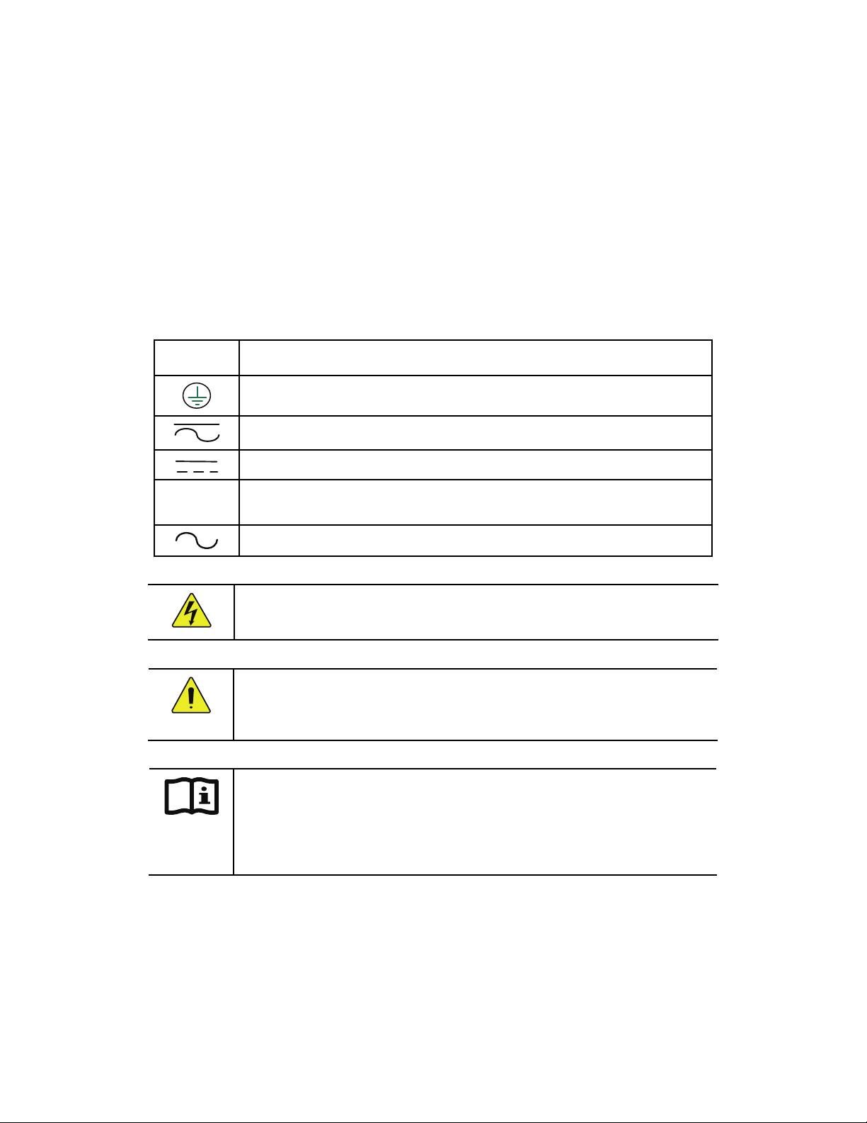
Symbols Used
Symbol Description
Ground
AC Current
DC Current
Single-Phase
∅
Sine Wave
WARNING: Hazard to Human Life
This type of notation indicates that the hazard could be harmful to human life.
CAUTION: Hazard to Equipment
This type of notation indicates that the hazard may cause damage to
the equipment.
IMPORTANT:
This type of notation indicates that the information provided is important to
the installation, operation and/or maintenance of the equipment. Failure to
follow the recommendations in such a notation could result in voiding the
equipment warranty.
Audience
These instructions are for use by qualified personnel who meet all local and governmental code
requirements for licensing and training for the installation of electrical power systems with AC and DC
voltage up to 240 Vac and 150 Vdc.
900-0095-01-00 Rev A 1
Page 4
Important Safety Instructions
Definitions
Off-Grid
On-Grid
utility grid.
Grid-tie, Grid-interactive, Grid-intertie
capable of returning (selling) electricity back to the utility grid.
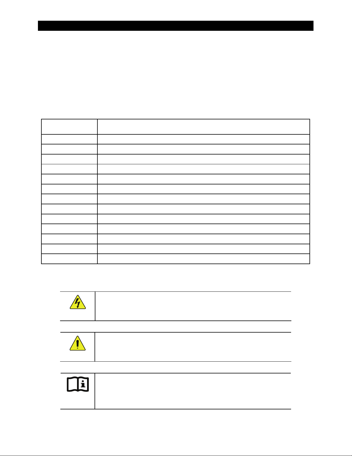
Table 1 Acronyms
Acronym Definition
AC Alternating Current
ANSI American National Standards Institute
DC Direct Current
FCC Federal Communications Commission (North America)
GND Ground
IEEE Institute of Electrical and Electronics Engineers
– Utility Grid Power
– Utility Grid power is available for use. Does not imply the ability to sell power back to the
available for use.
is not
– Utility Grid Power is available for use and the system is
N AC Neutral
NEC National Electric Code (North America)
NFPA National Fire Protection Association
OSHA Occupational Safety and Health Association
PV Photovoltaic
RE Renewable Energy
UL Underwriters Laboratory
General Safety
WARNING: Limitations on Use
This equipment is NOT intended for use with life support equipment or other
medical equipment or devices.
CAUTION: Equipment Damage
Only use components or accessories recommended or sold by OutBack Power
Systems or its authorized agents.
IMPORTANT:
Do not attempt to install this equipment if it appears to be damaged in any
way. See the Troubleshooting Section for instructions on how to return the
equipment if you know, or suspect, it is damaged.
2 900-0095-01-00 Rev A
Page 5
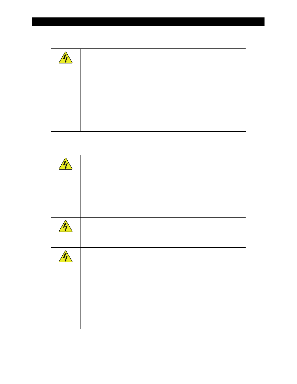
Personal Safety
WARNING: Personal Injury
This equipment weighs approximately 98 lbs (44.5 kg). Use safe lifting
techniques when lifting this equipment as prescribed by the Occupational
Safety and Health Association (OSHA) or other local codes.
Use standard safety equipment such as safety glasses, ear protection, steeltoed safety boots, safety hard hats, etc. as prescribed by the Occupational
Safety and Health Association (or other local codes) when working on this
equipment.
Use standard safety practices when working with electrical equipment
(e.g., remove all jewelry, use insulated tools, wear cotton clothing, etc.)
Never work alone when installing or servicing this equipment. Have
someone nearby that can come to your aid if necessary.
FLEXpower ONE System Safety
WARNING: Lethal Voltage
Review the system configuration to identify all possible sources of energy.
Ensure ALL sources of power are disconnected before performing any
installation or maintenance on this equipment. Confirm that the terminals
are de-energized using a validated voltmeter (rated for a minimum
1000 Vac and 1000 Vdc) to verify the de-energized condition.
Do not perform any servicing other than that specified in the installation
instructions unless qualified to do so or as instructed to do so by OutBack
Power Systems Technical Support personnel.
Important Safety Instructions
900-0095-01-00 Rev A
WARNING: Burn Hazard
Internal parts can become hot during operation. Do not remove the cover
during operation or touch any internal parts. Be sure to allow them sufficient
time to cool down before attempting to perform any maintenance.
WARNING: Fire Hazard
In residential installations: check for multi-wire branch circuit wiring at the
location for the installation. A possible fire hazard can exist if 120 Vac only
sources (such as inverters and generators) are wired incorrectly into
120/240 Vac panels containing multi-wire branch circuits. Consult the local
electric code for assistance.
Do not place combustible or flammable materials within 12 feet (3.7 m) of
the equipment.
Use only the recommended cable sizes (or greater) for AC and DC
conductors in compliance with local codes. Ensure all conductors and
connections are in good condition. Do not operate the unit with damaged
or substandard cabling.
3
Page 6
PV Safety
Important Safety Instructions
CAUTION: Equipment Damage
When connecting cables from the inverter to the battery terminals, ensure
the proper polarity is observed. Connecting the cables incorrectly can
damage or destroy the equipment.
Thoroughly inspect the equipment prior to energizing. Verify that no tools
or equipment have been inadvertently left behind.
Ensure clearance requirements are strictly enforced and that all vents are
clear of obstructions that can prevent proper air flow around or through
the unit.
Sensitive electronics inside the equipment can be destroyed by static
electricity. Be sure to discharge any static electricity built up before
touching the equipment and wear appropriate protective gear.
WARNING: Shock Hazard
Photovoltaic (PV) arrays can be energized with minimal ambient light available.
Therefore to ensure a safe disconnect from the system, be sure to install a PV
disconnect, breaker, or accessible fuse box (depending on local code
requirements).
CAUTION: Equipment Damage
PV Arrays must be wired with correct polarity (positive-to-positive, negative-tonegative). Connecting the cables incorrectly can damage or destroy the
equipment.
Battery Safety
WARNING: Electrocution Hazard
Use the battery types recommended by OutBack Power Systems. Follow
the battery manufacturer’s recommendations for installation and
maintenance.
Ensure clearance requirements are strictly enforced around batteries.
Ensure the area around the batteries is well ventilated and clean of debris.
Always use insulated tools. Avoid dropping tools onto batteries or other
electrical parts.
Keep plenty of fresh water and soap nearby in case battery acid contacts
skin, clothing, or eyes.
If you need to remove a battery, always remove the ground terminal from
the battery first. Make sure all accessories are turned off so you don’t cause
a spark.
If a remote or automatic generator control system is used, disable the
automatic starting circuit and/or disconnect the generator from its starting
battery while performing maintenance to prevent accidental starting.
4 900-0095-01-00 Rev A
Page 7
Important Safety Instructions
WARNING: Fire or Burn Hazard
Ensure the cables are properly sized. Failure to size the cables properly can
result in a Fire Hazard.
Wear complete eye protection and clothing protection when working with
batteries. Avoid touching your eyes while working near batteries.
If battery acid contacts skin or clothing, wash immediately with soap and
water. If acid enters the eye, immediately flood it with running cold water
for at least 20 minutes and get medical attention immediately.
Never smoke or allow a spark or flame near the batteries.
Keep plenty of fresh water and soap nearby in case battery acid contacts
skin, clothing, or eyes.
WARNING: Explosion Hazard
Never charge a frozen battery. A flooded battery discharged to 40% SOC (stateof-charge) can freeze at or below -8.9° C (16° F).
CAUTION: Equipment Damage
When connecting cables from the DC input breaker to the battery terminals,
ensure proper polarity is observed (positive-to-positive, negative-to-negative).
Connecting the cables incorrectly can damage or destroy the equipment.
IMPORTANT:
Baking Soda neutralizes lead-acid battery electrolyte.
Vinegar neutralizes NiCad and NiFe battery electrolyte.
Have a supply of either substance readily available if using these types
of batteries.
Regulatory References
National Electric Code (NEC) Article 690, (current edition)
Canadian Electrical Code, Part I (CSA 107.1)
UL 1741-2005 Static Inverter and Charge Controllers for Use in Photovoltaic Power Systems
American National Standards Institute/National Fire Protection Agency (ANSI/NFPA) 70
Recycling Information
IMPORTANT: Recycle Electronics and Batteries
Batteries are considered hazardous waste and must be recycled according to
local jurisdiction. Inverters and other electronics contain metals and plastics
that can (and should) be recycled. The following are some websites and phone
numbers that provide information and “how” and “where” to recycle batteries
and other electronic equipment.
900-0095-01-00 Rev A
OutBack Power Systems strongly encourages you to learn about recycling and
to dispose of recyclable items accordingly. The Earth, and OutBack Power
Systems, thanks you for that effort.
5
Page 8

Earth 911
Web site: www.Earth911.com
Address: 14646 N. Kierland Blvd., Suite 100
Scottsdale, AZ 85254
Phone: +1.480.337.3025 (direct)
Environmental Protection Agency, USA
Web site: www.epa.gov/recyclecity/
Phone: +1.415.947.8000
(Monday –Friday 8:00 AM to 12:00 PM and 1:00 PM to 4:00 PM PST)
Email: r9.recyclecity@epa.gov
Keep America Beautiful, USA
Web site: www.kab.org/
Address: 1010 Washington Boulevard
Stamford, CT 06901
Phone: +1.203.659.3000 (Main number)
Fax: +1.203.659.3001
Email: info@kab.org
Important Safety Instructions
Office of Waste Management, Canada
Address: Office of Waste Management
Conservation and Protection
Environment Canada
Ottawa, Ontaro K1A 0H3
Phone: +1. 819.997.2800
Web site: http://www.portaec.net/library/recycling/recycling_in_canada.html
National Institute of Recyclers, Mexico
Web site: http://www.inare.org.mx/
Email: a57841279@prodigy.net.mx, margarita@inare.org.mx
Phone: 55.57.85.9160
Fax:
55.57.84.1279
EuroRecycle.net
The following website provides general information about Recycling in Europe. It also provides a list
of companies and organizations that provide recycling information or assistance.
Web site: http://euro.recycle.net/assn/index.html
E-mail: http://euro.recycle.net/cgi-bin/feedback1.cgi?w=27
(This is an on
line form providing a means to contact
the owners of the website.)
6 900-0095-01-00 Rev A
Page 9

Table of Contents
Important Safety Instructions ...................................................................1
Symbols Used ........................................................................................................................................................................1
Audience .................................................................................................................................................................................1
Definitions...............................................................................................................................................................................2
General Safety .......................................................................................................................................................................2
Personal Safety......................................................................................................................................................................3
FLEXpower ONE System Safety.......................................................................................................................................3
PV Safety..................................................................................................................................................................................4
Battery Safety.........................................................................................................................................................................4
Regulatory References........................................................................................................................................................5
Recycling Information ........................................................................................................................................................5
Earth 911 .............................................................................................................................................................................................6
Environmental Protection Agency, USA...................................................................................................................................6
Keep America Beautiful, USA .......................................................................................................................................................6
Office of Waste Management, Canada .....................................................................................................................................6
National Institute of Recyclers, Mexico..................................................................................................................................... 6
EuroRecycle.net................................................................................................................................................................................6
Introduction.............................................................................................11
Components .......................................................................................................................................................................12
Applications ........................................................................................................................................................................ 13
On-Grid Applications ....................................................................................................................................................................13
Off-Grid Applications....................................................................................................................................................................14
Grid-Interactive Applications.....................................................................................................................................................14
PV Array Planning ..........................................................................................................................................................................15
Battery Bank Planning..................................................................................................................................................................15
Generator Requirements................................................................................................................................................ 16
Preparation.......................................................................................................................................................................... 17
Tools Required ................................................................................................................................................................................17
Materials Required.........................................................................................................................................................................17
Accessories.......................................................................................................................................................................................17
Location.............................................................................................................................................................................................17
Environmental.................................................................................................................................................................................17
Clearance and Access Requirements .........................................................................................................................18
Dimensions..........................................................................................................................................................................19
Conduit and Knockout Preparation............................................................................................................................ 20
Mounting.............................................................................................................................................................................. 21
Removing the Covers....................................................................................................................................................... 24
Accessing the Wiring Compartments ........................................................................................................................ 25
Wiring ....................................................................................................................................................................................26
Grounding ........................................................................................................................................................................................26
DC Connections..............................................................................................................................................................................27
900-0095-01-00 Rev A 7
Page 10

Table of Contents
AC Connections ..............................................................................................................................................................................31
Functional Test/Commissioning..................................................................................................................................33
Pre-startup Procedures ................................................................................................................................................................33
Energize/Startup ............................................................................................................................................................................33
Reassembling the Enclosures .......................................................................................................................................35
Operation.................................................................................................39
Setting Basic Parameters ................................................................................................................................................ 39
MATE2 Settings...............................................................................................................................................................................39
Charger Settings.............................................................................................................................................................................39
Setting Time, Date & Display on the MATE2.........................................................................................................................40
Selecting the AC Source and AC Input Limit on the Inverter..........................................................................................42
Accessing the Advanced Menu.................................................................................................................................................43
Setting Battery Amp-Hours and Return Amps using the FLEXnet DC Monitor ........................................................44
Setting Charging Parameters.....................................................................................................................................................45
De-energize/Shutdown ...............................................................................................................................................................46
Specifications...........................................................................................49
Feature Matrix .................................................................................................................................................................... 49
Electrical Specifications, 120 Vac/60 Hz Models .................................................................................................... 50
Mechanical Specifications, 120 Vac/60 Hz Models................................................................................................ 50
Electrical Specifications, 230 Vac/50 Hz Models .................................................................................................... 51
Mechanical Specifications, 230 Vac/50 Hz Models................................................................................................ 51
Surge Protector.................................................................................................................................................................. 52
LEDs ....................................................................................................................................................................................................52
Renewable Energy Input & Storage............................................................................................................................53
PV Sizing............................................................................................................................................................................................53
Battery Bank Sizing........................................................................................................................................................................53
Amp-Hour Requirements............................................................................................................................................................53
Wiring Configurations .............................................................................59
FLEXpower ONE with FLEXnet DC Monitor and GFDI.......................................................................................... 61
FLEXpower ONE with FLEXnet DC Monitor Only (no GFDI)............................................................................... 62
FLEXpower ONE with GFDI Only (no FLEXnet DC Monitor)...............................................................................63
FLEXpower ONE (no FLEXnet DC Monitor or GFDI) .............................................................................................. 64
Warranty ..................................................................................................65
How to Arrange for Warranty Service ........................................................................................................................ 66
Return Material Authorization (RMA)......................................................................................................................................66
Returning Product to OutBack ..................................................................................................................................................66
Index ........................................................................................................67
8 900-0095-01-00 Rev A
Page 11

Table of Contents
List of Tables
Table 1 Acronyms.............................................................................................................................................................................. 2
Table 2 Basic Components of a FLEXpower ONE System..................................................................................................12
Table 3 Ground Conductor Size and Torque Requirements.............................................................................................26
Table 4 DC Conductor Size and Torque Requirements......................................................................................................27
Table 5 AC Conductor Size and Torque Requirements......................................................................................................31
Table 6 Feature Matrix...................................................................................................................................................................49
Table 7
Table 8 Worksheet
Worksheet for Determining Average Daily Load in Amp-hours
for Determining Battery Bank Size
.................................................................................................57
............................................................56
900-0095-01-00 Rev A 9
Page 12

Table of Contents
List of Figures
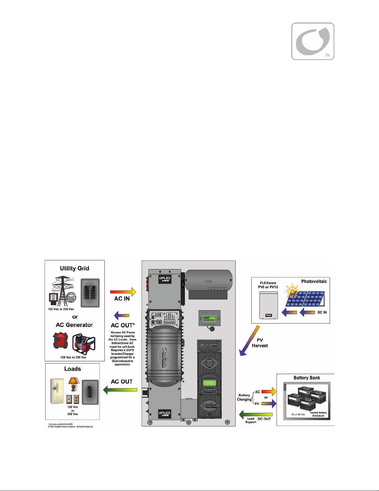
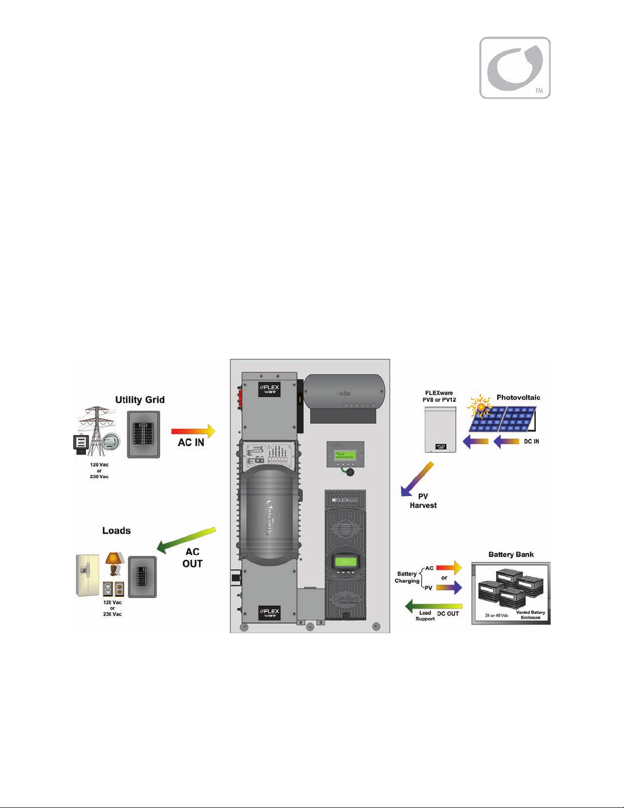
Figure 1 FLEXpower ONE System Overview............................................................................................................................11
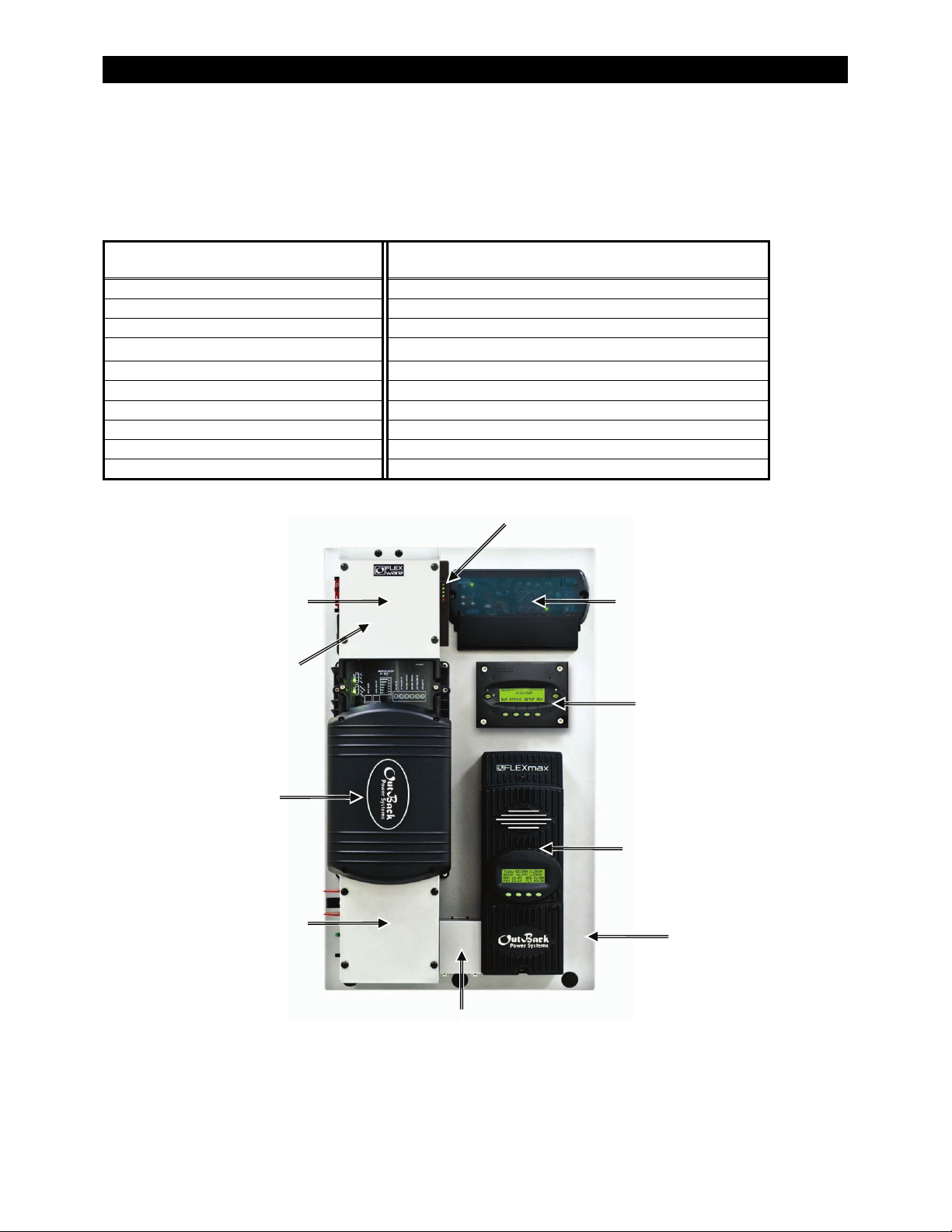
Figure 2 Basic Components of a FLEXpower ONE System..................................................................................................12
Figure 3 On-Grid Applications (Example).................................................................................................................................13
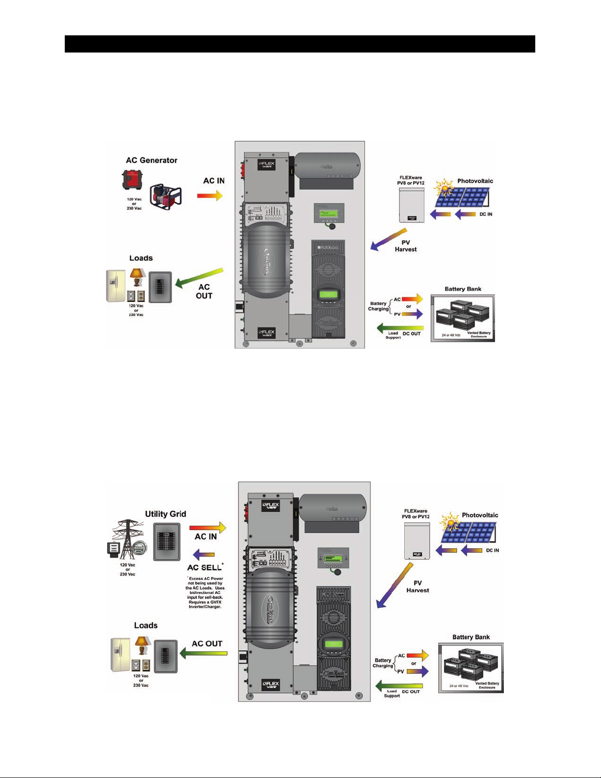
Figure 4 Off-Grid Applications (Example).................................................................................................................................14
Figure 5 Grid-Interactive Applications (Example)..................................................................................................................14
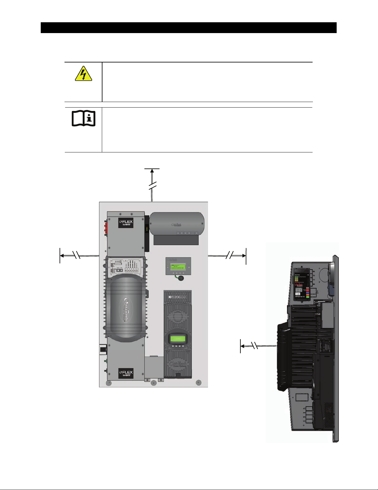
Figure 6 Clearance and Access Requirements........................................................................................................................18
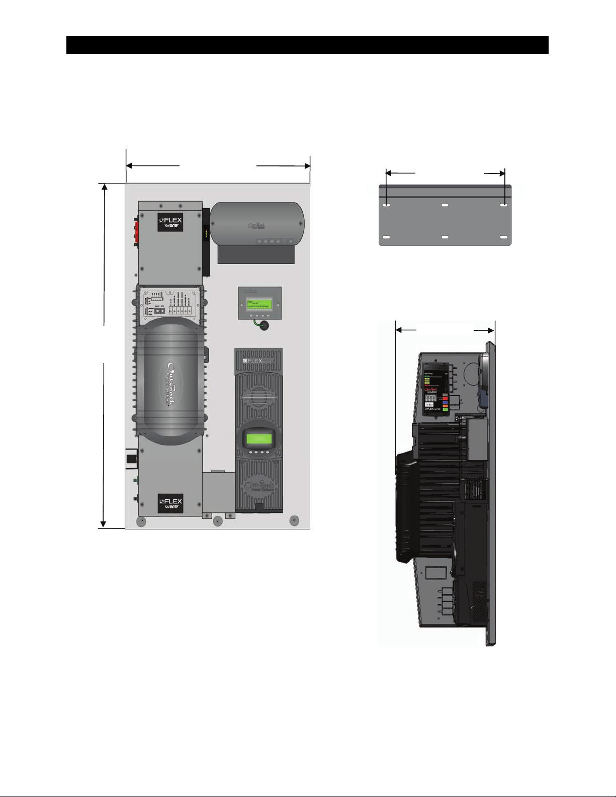
Figure 7 Dimensions........................................................................................................................................................................19
Figure 8 Conduit and Knockout Preparation...........................................................................................................................20
Figure 9 Installing the Mounting Bracket .................................................................................................................................22
Figure 10 Attaching the Mounting Plate to the Mounting Bracket ...................................................................................23
Figure 11 Removing the Covers.....................................................................................................................................................24
Figure 12 Wiring and Breaker Compartment.............................................................................................................................25
Figure 13 Ground Connections......................................................................................................................................................27
Figure 14 Battery Connections with the FLEXnet DC Monitor.............................................................................................28
Figure 15 Battery Connections without the FLEXnet DC.......................................................................................................29
Figure 16 PV Connections with a FLEXnet DC Monitor..........................................................................................................30
Figure 17 AC IN Connections...........................................................................................................................................................31
Figure 18 AC OUT Connections......................................................................................................................................................32
Figure 19 Energize Procedures.......................................................................................................................................................33
Figure 20 Functional Test Procedures for Initial Startup........................................................................................................34
Figure 21 Replacing the Raceway and FLEXmax 80 Front Cover........................................................................................35
Figure 22 Replacing the Inverter’s AC Terminal Access Cover.............................................................................................35
Figure 23 Replacing the AC Enclosure Front Cover.................................................................................................................36
Figure 24 Replacing the AC Enclosure Top Cover....................................................................................................................36
Figure 25 Replacing the DC Enclosure Front Cover.................................................................................................................37
Figure 26 Replacing the DC Cover.................................................................................................................................................37
Figure 27 MATE2 Setup Screen (Page 1) .....................................................................................................................................40
Figure 28 MATE2 Setup Screen (Page 2 and 3) .........................................................................................................................41
Figure 29 Inverter Setup Screen – Selecting AC Source.........................................................................................................42
Figure 30 Accessing the Advanced Menus.................................................................................................................................43
Figure 31 Setting Battery Amp-hours and Return Amps.......................................................................................................44
Figure 32 Setting Input Source and Current Limit...................................................................................................................45
Figure 33 Shutdown Procedures....................................................................................................................................................46
Figure 34 Functional Test Procedures to Confirm the Unit is De-energized...................................................................47
Figure 35 FLEXpower ONE with FLEXnet DC Monitor and GFDI.........................................................................................61
Figure 36 FLEXpower ONE with FLEXnet DC Monitor Only (No GFDI)..............................................................................62
Figure 37 FLEXpower ONE with GFDI Only (no FLEXnet DC Monitor)..............................................................................63
Figure 38 FLEXpower ONE (no FLEXnet DC Monitor or GFDI).............................................................................................64
10 900-0095-01-00 Rev A
Page 13
Introduction
Thank you for choosing a FLEXpower ONE System from OutBack Power Systems. FLEXpower ONE is
an integrated power system solution designed to be quick to install and easy to use.
The FLEXpower ONE System is intended for off-grid and on-grid applications up to 3.6 kW. It is
intended for use with photovoltaic (PV) modules for harvesting energy and a battery bank for energy
storage. FLEXpower ONE can also be configured as “Grid-interactive” meaning that excess energy
(energy that exceeds usage) will be returned to the Grid (Sell Mode).
The FLEXpower ONE System is designed with the following features:
3.5 kW and 3.6 kW units.
120 Vac/60 Hz configurations and 230/50 Hz configurations
Rated for Indoor Installations
Includes mounting bracket for wall-mounting
Charge controller uses MPPT technology to maximize the harvest from solar modules
Grid-interactive capable (requires a configuration that features a GVFX Inverter)
Battery status monitor takes independent shunt measurements of PV and inverter power
Includes OutBack’s Surge Protector for additional protection against damaging power surges
Figure 1 FLEXpower ONE System Overview
900-0095-01-00 Rev A 11
Page 14
Introduction
Components
A complete FLEXpower ONE is composed of the following components. See page 49 for details on
specific configurations.
Table 2 Basic Components of a FLEXpower ONE System
Components Documentation
FX Series Inverter/Charger
Mounting Plate
(with mounting bracket)
(VFX or GVFX)
FLEXpower ONE Installation Manual
(this book)
MATE Remote Control and Display
AC Enclosure
DC Enclosure
(120 V-NA or 230 V-EU)
(125, 175, or 250A)
MATE Installation and User’s Manual
Additional Reference Documents
FLEXnet DC Battery Monitor FLEXnet DC Monitor
FLEXmax 80 Charge Controller FX or Grid-Interactive Programming Manual
Raceway FLEXmax 80 User’s Manual
HUB4 Communication Manager HUB4 Communication Manager User’s Manual
FLEXware Surge Protector
FLEXnet DC Battery Monitor
FW250-AC-120V-NA
Or
FW250-AC-230V EU
FLE
e Surge Protector
Xwar
(mounted under AC cover)
HUB4 Communication Manager
MATE2 Remote Control
FX Series
Inverter/Charger
FLEXmax 80 Charge Controller
FW250-DC-125,
FW250-DC-150,
or
FW250-DC 250
Raceway
Mounting Plate
Figure 2 Basic Components of a FLEXpower ONE System
12 900-0095-01-00 Rev A
Page 15
Planning
Applications
The FLEXpower ONE is intended for on-grid, off-grid, and grid-interactive applications. It is
designed to use photovoltaic (PV) panels to harvest solar energy and a battery bank to store the
harvested energy.
On-Grid Applications
In on-grid applications, the FLEXpower ONE can use the grid power as the primary power source or as
the backup source of power. If the FLEXpower ONE is used as backup to the grid, the FLEXpower ONE
will take over when the grid fails. If the FLEXpower ONE is used as the primary source, the grid power
will be used when the batteries have been drained. In this situation, the AC power or PV harvest can
be used to recharge the battery bank.
Figure 3 On-Grid Applications (Example)
900-0095-01-00 Rev A 13
Page 16
Planning
Off-Grid Applications
In off-grid applications, the FLEXpower ONE can use the harvested energy from the battery bank as
the primary power source. An AC generator can also be connected to support the system
when required.
Figure 4 Off-Grid Applications (Example)
Grid-Interactive Applications
In grid-interactive applications, grid power is used to run the loads. When excess PV is available from
the batteries, the FLEXpower ONE supports those loads with the PV. When the PV exceeds the load
requirements, the FLEXpower ONE sells that excess power back through its input, to the utility grid.
When the utility grid is not available, the FLEXpower ONE takes over to run the loads with PV and
energy stored in the battery bank.
Figure 5 Grid-Interactive Applications (Example)
14 900-0095-01-00 Rev A
Page 17

Planning
PV Array Planning
The FLEXpower ONE is designed to use PV input to charge the battery bank. The FLEXmax 80 charge
controller(s) integrated into the FLEXpower ONE System uses Maximum Power Point Tracking (MPPT)
technology to maximize the PV harvest. A PV Combiner box (not included) may be required for
multiple PV strings. PV Combiner Boxes are available from OutBack Power Systems for 8 to 12
PV strings.
FLEXpower ONE includes one FLEXmax 80 Charge Controller. The charge controller allows input from
a single PV array. The PV input can support the following PV configuration.
4,000 W
150 V
64 A I
on 48 Vdc system, 2,000 W
STC
including local temperature correction factor per NEC 690.7
OC
maximum PV array current per NEC 690.8
SC
on 24 Vdc system
STC
For a PV Planning Tool, see the following website.
http://outbackpower.com/resources/string_sizing_tool/
Battery Bank Planning
Types of Batteries
The FLEXpower ONE System supports a 24 or 48 Vdc battery bank, depending on the inverter that
is featured in the configuration. Before constructing a battery bank, check the model number on
the side of the inverter to confirm the nominal battery voltage.
A vented enclosure for the battery bank may be required by electric code.
Bank Sizing
In general, the size of the loads (watts) and the required backup period (hours) will determine best size
for the battery bank. To calculate this, use the information provided on page 53 through page 57.
Worksheets are provided
for assistance.
900-0095-01-00 Rev A
15
Page 18

Generator Requirements
IMPORTANT:
All connections must comply with local electric code.
Generator grounding and neutral-to-ground bonding should be
provided in accordance with specific system configuration and
national/local code requirements.
Follow the manufacturer’s recommendations for fuel type and
maintenance.
Planning
The following are general requirements for using a generator with the FLEXpower ONE
Electrical Requirements
.
~ North American Applications: 120 Vac / 60 Hz
~ European Applications: 230 Vac / 50 Hz
Minimum available generator power* should be equal to or greater than nominal inverter rating
(*after de-ratings for peak verses continuous power, for load power factor considerations, for
altitude, and for ambient temperature).
~ A generator with a de-rated power specification smaller than that of the inverter may not be
able to handle all downstream AC loads and/or the built-in battery charger.
~ A generator with a de-rated power specification larger that that of the inverter may be
required to handle the built-in battery charger as well as all downstream AC loads.
~ Available power from the generator may be further limited by ratings for circuit breakers
and/or generator output connectors. “Full” generator output power may not be available
from a single generator connector.
~ Generator sizing may be affected by start-up surge current requirements of 3X to 6X normal
operating current for some loads (i.e., motors with large loads).
~ The inverter and/or downstream loads may have difficulty operating from poorly-regulated
generators (voltage, frequency, load).
Grid-interactive inverters typically require inverter-type generators.
Split-phase generators (i.e., 120/240 Vac / 60 Hz) can be adapted to a single-phase inverter using
an autotransformer such as the X-240. For additional information, see…
~ PSX-240 Manual: http://www.outbackpower.com/pdf/manuals/PSX-240_Installation
Manual.pdf
~ X-240 Manual: http://www.outbackpower.com/pdf/manuals/
The OutBack MATE can be used to program an inverter’s AUX output to start and stop a generator.
fw-x240.pdf
This 12 V output can often control a two-wire-start generator directly. Three-wire-start generators
require an interface such as an Atkinson module. For additional information, see…
~ OutBack Power Systems AGS Brochure:
http://www.outbackpower.com/pdf/brochures/Automatic_Generator_Start.pdf
~ OutBack Power Systems MATE Manual:
http://www.outbackpower.com/pdf/manuals/mate.pdf
~ Atkinson Electronics: http://atkinsonelectronics.com/
16 900-0095-01-00 Rev A
Page 19

Preparation
Tools Required
Planning
The following tools may be required for installing this equipment.
Wire cutters/strippers Drill and drill-bits
Torque wrenches Ratchet drives
Assorted insulated screw-drivers
Digital Voltmeter
Materials Required
The following materials may be required for installing this equipment.
Conductors for wiring
Conduits, bushings
Anchor Bolts (x4) or Dry-wall (x6) screws for mounting
Plywood (optional, for additional wall support)
Accessories
The following accessories are available for purchase.
PV8/PV12 Combiner Box
See the OutBack catalog for a complete list of other parts and components that are available.
Location
FLEXpower ONE is rated for indoor installations.
In areas where seismic activity is a concern, consult local code for seismic safety requirements.
Environmental
This unit is performance rated at 25°C (77°F). Exposure to extreme hot temperatures can reduce
the unit’s performance. When used in an outdoor installation, use a shading structure to avoid
direct exposure to sunlight.
The mounting surface should be vertical, smooth, and able to support three (3) times the weight
of the enclosure (98 lb, or 44.5 kg. This may require additional support for wall-mounted
installations.
900-0095-01-00 Rev A
17
Page 20
Clearance and Access Requirements
WARNING: Fire/Explosion Hazard
Do not place combustible or flammable materials within 12 feet (3.7 m) of
the equipment. This unit employs mechanical relays and is not ignitionprotected. Fumes or spills from flammable materials could be ignited by sparks.
IMPORTANT:
Clearance and access requirements may vary by location. Maintaining a 36”
(0.91 cm) clear space in front of the system for access is recommended.
Consult local electric code to confirm clearance and access requirements for
the specific location.
Planning
12” (30.5 cm)
(Minimum)
12” (30.5 cm)
(Minimum)
Minimum recommended
clearance above and on sides.
12” (30.5 cm)
(Minimum)
Side View
36” (91.4 cm)
(Minimum)
Minimum recommended
clearance in front.
Figure 6 Clearance and Access Requirements
18 900-0095-01-00 Rev A
Page 21
Dimensions
Planning
33½”
(851 cm)
19¾” (481 cm)
16” (41 cm)
Mounting Bracket
≈13” (33 cm)
Figure 7 Dimensions
900-0095-01-00 Rev A
19
Side View
Page 22
Planning
T
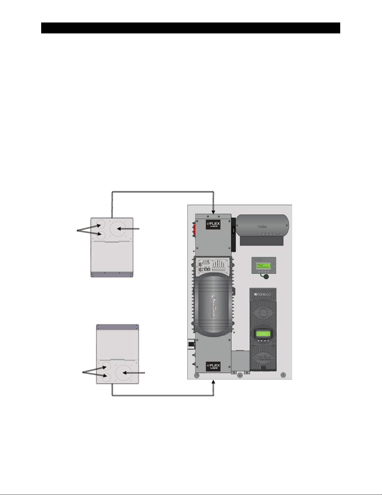
Conduit and Knockout Preparation
Knockouts (two 1”, one 2”) are provided on the ends of the AC and DC enclosures for routing cable
into the enclosures. Conduit and bushings are recommended to prevent damage to conductors from
sharp edges along knockout holes.
1. Remove the 2” knockout on the DC end to accommodate the larger battery cables and Remote
Temperature Sensor cable.
2. Remove the 1” knockout(s) on the AC end to accommodate the AC cabling.
3. Install conduit and bushings to protect the cable from damage from the sharp edges of the hole.
4. Ensure no debris or metal shavings have fallen into the enclosures.
AC End
1”
1”
op View
Front Side
Front Side
Bottom View
2”
2”
DC End
Figure 8 Conduit and Knockout Preparation
20 900-0095-01-00 Rev A
Page 23

Installation
The FLEXpower ONE system is designed for flexibility and easy installation. The system comes
attached to a mounting plate with the selected components pre-installed and wired. The Mounting
Plate attaches to a mounting bracket that attaches to a wall.
WARNING: Personal Injury
This equipment weighs 98 lbs (44.5 kg). Use safe lifting techniques when
lifting this equipment as prescribed by the Occupational Safety and Health
Association (OSHA) or other local codes.
Use standard safety equipment such as safety glasses, ear protection, steeltoed safety boots, safety hard hats, etc. as prescribed by the Occupational
Safety and Health Association (or other local codes) when working on this
equipment.
Use standard safety practices when working with electrical equipment
(e.g., remove all jewelry, use insulated tools, wear cotton clothing, etc.)
Never work alone when installing or servicing this equipment. Have
someone nearby that can come to your aid if necessary.
Mounting
The FLEXpower ONE is designed to be wall-mounted, indoors. The mounting bracket has six holes in
it with the outside holes measuring 16” center-to-center. This allows the mounting bracket to be
secured to wall studs 16” apart. If the wall studs are 24” apart, the center mounting holes should be
used to secure the bracket to the wall stud and the outside holes should be used for extra stability.
IMPORTANT:
The mounting surface should be able to hold three times the combined weight
of all the components. A sheet of ¾” plywood may be required to meet this
requirement. Check with local code to ensure regulatory compliance for
stability and cabling.
To install the Mounting Bracket:
1. Note the height of the Mounting Plate as indicated in Figure 7.
2. Place the Mounting Bracket at the desired height
recommended to hang at about eye level.
3. Secure the Mounting Bracket to the wall as shown in Figure 9. Use all six mounting slots provided
on the bracket, if possible.
4. Lift the Mounting Plate above the Mounting Bracket. Slip the top of the Mounting Plate over the
the Mounting Bracket. See Figure 10 on page 23.
angled lip
5. Secure the lower back flange of the Mounting Plate to the wall (with appropriate hardware), using
the rear flange slots
6. Insert all three 1” nylon hole plug
900-0095-01-00 Rev A 21
of
as shown in Figure 10 on page 23.
s into the rear slot access holes.
for the panel. The bottom of the bracket is
Page 24

Mounting the bracket to
wall studs 16” apart.
Mounting the bracket to
wall studs 24” apart.
Installation
Mounting the bracket
to plywood.
Figure 9 Installing the Mounting Bracket
900-0095-01-00 Rev A
22
Page 25

Installation
Lift the Mounting Plate
above the wall bracket.
Slip the top of the
Mounting Plate over
the angled lip of the
wall bracket.
Secure the Mounting Plate to the wall
at the 3 locations shown here.
Secure the Mounting Plate to the
wall at the 3 locations shown
below.
Figure 10 Attaching the Mounting Plate to the Mounting Bracket
900-0095-01-00 Rev A
23
Page 26

Removing the Covers
T
Remove the screws in
the AC Enclosure’s
Front Cover (x4).
Gently pull the Front
Cover away from the
chassis being careful
not to disconnect or
damage the wiring for
the Surge Protector.
The Front Cover cannot
be completely removed
due to the Surge
Protector wiring
(see page 52).
Remove the screws on
the Inverter Terminal
Access Cover (x2).
Remove the screws on the
AC Access Cover (x2).
Installation
Note: The AC Enclosure has two covers: the access cover
and the front cover. Both covers need to be opened to
make conductor connections. Once connections are
made, the access cover can be used for visual inspection,
so that the wiring will not be disturbed when inspected
by the local electrical authority.
Remove the screws
on the Inverter DC
Cover (x4).
Remove the screws on
the DC Enclosure
Front Cover (x4).
1
Remove the screws on
the Raceway (x2).
1
he Raceway and front cover on the FLEXmax 80 Charge
Controller only need to be removed if the FLEXnet DC
Monitor is included in the configuration.
1
Remove the screws on
the FLEXMax 80
Charge Controller
(x3).
Figure 11 Removing the Covers
24 900-0095-01-00 Rev A
Page 27

Accessing the Wiring Compartments
k
T
Installation
Internal components may vary from model to model.
Factory wiring is not shown.
FLEXnet DC Monitor
erminal Bus Bar for
Neutral Connections
AC Input, Output, & Bypass
Breakers (x3)
(120-NA: 60 A)
(230 EU : 30 A)
Mechanical Interloc
Breaker for AC Outlet (X1)
120-NA: 20 A
23-EU: 16 A
AC Outlet (X1)
AC Ground Bar
Battery Positive (+)
Battery Negative (–)
Inverter Terminal Enlargement
(If installed)
1
Shunt A
DC Ground Bar
Battery Disconnect
(125, 175, or 250 Adc)
Breaker for FNDC (1 A)
PV Disconnect (80 Adc)
1
Required by FLEXnet DC Monitor. Shunt A monitors inverter input and output
current. Shunt B monitors PV input current. Shunts are not present if the
FLEXnet DC Monitor is not part of the configuration. Shunt B is not present if the
FLEXmax 80 Charge Controller is not part of the configuration.
(if installed)
GFDI Breaker (1 Adc)
Shunt B
1
FLEXmax 80
Terminal Block
Enlargement
Figure 12 Wiring and Breaker Compartments
900-0095-01-00 Rev A
25
Page 28

Wiring
IMPORTANT:
All connections must comply with local electric code. Local code may
require sizes other than those recommended in this manual. For all wiring,
use copper conductors rated at 75°C minimum.
If the installation involves grid-tie activities such as selling power back to
the grid, per NEC 690, ensure the total value of the breakers installed in
either the main AC distribution panel or the AC sub-panel does not exceed
the total rating on the terminal distribution bus in the distribution panel. In
other words, if the main terminal distribution bus in the panel is rated for
100 amps, then the total value of all the breakers installed can not exceed
100 amps.
The size of the breaker installed to support the inverter should not exceed
60 A maximum.
When smaller AC sources are used, smaller AC wiring may be used (down to
the minimum sizes indicated in Tables 4 and 6). The external AC breakers
must be sized accordingly to protect smaller wires.
Installation
Grounding
IMPORTANT:
System grounding is the responsibility of the installer.
Grounding requirements may vary by location depending on the local
electric code. In North America, inverter systems are considered two
separate electrical systems and, therefore, are required by code to have
each system (AC and DC) connected to a ground electrode conductor (also
known as a primary system ground).
The AC and DC circuits are not bonded to the FLEXware enclosure.
The equipment ground is marked with this symbol:
WARNING:
Ensure there is only one Neutral-to-Ground Bond in the system.
FLEXpower ONE comes with a Neutral-to-Ground Bond installed. If a Neutralto-Ground bond exists elsewhere in the system, the Neutral-to-Ground Bond in
the FLEXpower ONE will need to be removed. See Figure 18. Check local code
for sp
ecific re
quirements.
The
Table 3 Ground Conductor Size and Torque Requirements
Terminal
Location
Ground Bar #12 AWG (3.3 mm2) 1/0 AWG (53.5 mm2) 35 in-lb (4 Nm)
Minimum Allowed
Conductor Size
Maximum Conductor
Size
Torque
Requirements
26 900-0095-01-00 Rev A
Page 29

Installation
Figure 13 Ground Connections
DC Connections
Table 4 DC Conductor Size and Torque Requirements
DC Terminal Minimum Allowed
Conductor Size
Battery Positive (+) 2/0 AWG (67.5mm2)
Battery Negative (–)
(Shunt)
PV Positive (+) #4 AWG (21.2 mm2)
PV Negative (–)
Ground Bus Bar #12 AWG (3.3 mm2) 1/0 AWG (53.5 mm2) 35 in-lb (4 Nm) N/A
2/0 AWG (67.5 mm2)
#4 AWG (21.2 mm2)
To make the battery connections in systems that have the FLEXnet DC Monitor, see Figure 14 on
page 28.
To make the battery connections in sys
tems that do not have
15 on page 29.
Maximum
Conductor Size
N/A (ring terminal) 50 in-lb (5.7 Nm) 175 Adc
N/A (ring terminal) 50 in-lb (5.7 Nm) N/A
#2 AWG (33.6 mm2) 35 in-lb (4 Nm) 80 Adc
#2 AWG (33.6 mm2) 35 in-lb (4 Nm) N/A
Torque
Requirements
Breaker
Size
the FLEXnet DC Monitor, see Figure
To make the PV connections, see Figure 16 on page 30.
900-0095-01-00 Rev A
27
Page 30

Installation
To make the battery connections in a system with the FLEXnet DC Monitor:
1. Remove all hardware from the side of Shunt A that is not connected to the Inverter.
2. Place the Inverter Negative (–) cable lug and Charge Controller Negative (–) cable lug onto
Shunt A. Secure in place with the Flat Washer, Lock Washer and Nut. Torque to 50 in-lb (5.7 Nm).
3. Connect the Battery (+) conductor to the DC Breaker lug closest to the Mounting Panel.
Torque to 50 in-lb (5.7 Nm).
4. Attach one end of the Battery Temperature Sensor (RTS) cable to the BATT TEMP port on the
Inverter and the other side to one of the batteries in the middle of the Battery Bank.
Internal components shown may vary from model to model.
Factory wiring is not shown.
See Table 4 on page 27
for recommended
Bolt
conductor sizes and
torque requirements.
Charge
Controller
Battery (–)
Lug
Lock Washer
Flat Washer
Shunt
CAUTION: Equipment Damage
The Battery
the first item installed on Shunt A.
Negative lug must be
CAUTION: Equipment Damage
Ensure
that correct polarity is
observed when connecting
battery cables.
Inverter
Battery (–)
Lug
Figure 14 Battery Connections with the FLEXnet DC Monitor
28 900-0095-01-00 Rev A
Page 31

Installation
Te
ost
g
To make the battery connections in a system without the FLEXnet DC Monitor:
1. Remove all hardware from the inverter’s battery negative (–) terminal post.
2. Place the Inverter Negative (–) cable lug and Charge Controller Negative (–) lug onto the terminal
post. Secure in place with the Flat Washer, Lock Washer and Nut. Torque to 50 in-lb (5.7 Nm).
3. Place the GFDI cable lug and Surge Protector DC Negative (–) cable lug onto the terminal post.
Secure in place with the next Lock Washer and Nut. Torque to 35 in-lb (4 Nm)
4. Connect the Battery (+) conductor to the DC Breaker lug closest to the Mounting Panel.
Torque to 50 in-lb (5.7 Nm).
5. Attach one end of the Battery Temperature Sensor (RTS) cable to the BATT TEMP port on the
Inverter and the other side to one of the batteries in the middle of the Battery Bank.
Internal components shown may vary from model to
GFDI Lu
Inverter
Battery (–)
Lug
model. Factory wiring is not shown.
Surge
Protector
Lug
Charge
Controller
Battery (–)
Lug
See Table 4 on
page 27 for
conductor sizes
and torque
requirements.
Nut
Lock Washer
Nut
Lock Washer
Flat Washer
Inverter
Battery (–)
rminal P
CAUTION: Equipment Damage
The Battery Negati
first item installed on the inverter post.
Figure 15 Battery Connections without the FLEXnet DC
900-0095-01-00 Rev A
29
ve lug must be the
CAUTION: Equipment Damage
Ensure that correct polarity is
observed when connecting
battery cables.
Page 32

Installation
To make the PV connections:
1. Ensure the PV array is properly grounded.
2. Route the PV (–) through the bottom of the DC enclosure and into the wiring compartment of the
FM80 charge controller. Connect the PV (–) conductor to the PV (–) terminal in the FM80 charge
controller. Torque to 35 in-lb (4 Nm).
3. Connect the PV (+) to the top terminal of the PV Disconnect in the DC Enclosure. Torque
to 35 in-lb (4 Nm).
Internal components shown may vary from model to model. Factory wiring is not shown.
Figure 16 PV Connections with a FLEXnet DC Monitor
900-0095-01-00 Rev A
30
Page 33

AC Connections
q
WARNING: Fire Hazard
Multi-wire branch circuits in residential installations can create a potential fire
Table 5 AC Conductor Size and Torque Requirements
hazard with inverter installations. Be sure to check for multi-wire branch circuits
before making any AC connections and make any changes required to remove
the hazard.
Installation
AC Terminal Minimum Allowed
Conductor Size
Maximum
Conductor Size
Torque
Requirements
Breaker
Size
AC IN #14 AWG (2.1 mm2) 1/0 AWG (53.5 mm2) 35 in-lb (4 Nm) 60 Aac
AC OUT #14 AWG (2.1 mm2) 1/0 AWG (53.5 mm2) 35 in-lb (4 Nm) 60 Aac
Neutral Bus Bar #14 AWG (2.1 mm2) 1/0 AWG (53.5 mm2) 35 in-lb (4 Nm) N/A
Internal components shown may vary from model to model.
Neutral-to-Ground
Bond
1
Factory wiring is not shown.
1
See the WARNING on
page 32 for additional
See Table 5 for recommended conductor
sizes and tor
ue requirements.
information.
Figure 17 AC IN Connections
900-0095-01-00 Rev A
31
Page 34

Installation
WARNING: Shock Hazard
Ensure there is only one Neutral-to-Ground Bond in the system.
FLEXpower ONE comes with a Neutral-to-Ground Bond installed. If a Neutralto-Ground bond exists elsewhere in the system (e.g., in the main panel, or a
generator), the Neutral-to-Ground Bond in the FLEXpower ONE AC Enclosure
will need to be removed. See Figure 18. Check local code for specific
reme
requi
nts.
The
AC Enclosure
See Table 5 on page 32 for recommended
conductor sizes and torque requirements.
Factory-installed
Neutral-To-Ground
Bond
The factory-installed
Neutral-to-Ground Bond
must be removed if
another Neutral-toGround Bond exists
elsewhere in the
configuration.
Internal components shown may vary from model to model.
Factory wiring is not shown.
Figure 18 AC OUT Connections
32 900-0095-01-00 Rev A
Page 35

Functional Test/Commissioning
Pre-startup Procedures
1. Double-check all wiring connections.
2. Inspect the enclosure to ensure no tools or debris has been left inside.
Energize/Startup
1. Using a digital volt-meter (DVM), verify 24 or
48 Vdc on the Battery terminals (i.e., place
DVM leads on and
3
5
A
Confirm that the voltage is correct for the
inverter model. Confirm the polarity.
CAUTION
Incorrect battery polarity wil
: Equipment Damage
2. Close the DC Breakers from the battery bank
to the inverter.
1+
2
See Figure 19.
Installation
1-
in Figure 20).
l damage the i
nverter.
Figure 19 Energize Procedures
3. Close the AC Output Breakers.
See Figure 19.
4. Using a digital voltmeter, verify 120 Vac on
the AC Breakers (i.e., place voltmeter leads
4+
on
5. Close the AC Input Breakers.
and
4–
in Figure 20).
5
See Figure 19.
6. Using a digital voltmeter, verify 120 Vac on
the AC Breakers (i.e., place voltmeter leads
6+
on
7. Close the PV input Breakers.
and
6–
in Figure 20).
7
See Figure 19.
2
8. Using a digital voltmeter, verify the voltage
on the PV terminal does not equal zero
(i.e., place voltmeter leads on
8+
and
8–
in Figure 20).
7
9. Connect a small AC load and test for proper
functionality.
A
Outlets are model-dependent.
120 V systems will have a 120V outlet,
230 V Systems will have a 230 V outlet.
900-0095-01-00 Rev A
33
Page 36

4+
4–
Installation
6–
6+
Note: The shunt
may or may not be
installed on your
model. Use the
same test point in
all cases.
1–
1+
8+
8–
Figure 20 Functional Test Points for Energizing Systems
34 900-0095-01-00 Rev A
Page 37

Reassembling the Enclosures
Mounting
Slot
Cabling not shown.
Lip
Raceway
Panel
FM80
Front
Cover
Installation
To Replace the Raceway:
1. Slip the lip on the Raceway into the
slot on the mounting panel.
2. Align the holes on the bottom of
the Raceway with the holes
provided on the mounting panel.
3. Secure the Raceway in place with
the screws provided.
To Replace the FLEXmax 80
Front Cover:
1. Align the holes on the FM80
Front Cover.
2. Secure the FM80 Front Cover in
place with the screws provided.
Figure 21 Replacing the Raceway and FLEXmax 80 Front Cover
To Replace the Inverter’s AC
Terminal Access Cover:
Inverter’s AC T
Access Cover
erminal
1. Align the holes on the sides of the
cover with the holes on the inverter.
2. Secure the cover in place with the
screws provided.
Cabling not shown.
Figure 22 Replacing the Inverter’s AC Terminal Access Cover
900-0095-01-00 Rev A
35
Page 38

Installation
p
The Front Cover of the AC Enclosure will not be
completely removed due to the surge protector
cabling. Work with care not to damage the
surge protector or dislodge the cabling as you
replace the Front Cover.
To Replace the Front of AC Enclosure:
1. Align the holes (x4) in the enclosure front cover
with the holes in the chassis.
2. Replace the screws (x4) removed in the beginning.
Cabling not shown.
Figure 23 Replacing the AC Enclosure Front Cover
Notch
AC To
CoverLip
To Replace the Top of AC Enclosure:
1. Slip the Lip on the AC Top Cover into the notch in
the chassis.
2. Align the holes (x2) in the top cover with the holes
in the front cover.
2. Replace the screws (x2) removed in the beginning.
Cabling not shown.
Figure 24 Replacing the AC Enclosure Top Cover
900-0095-01-00 Rev A
36
Page 39

To Replace the DC Enclosure Front Cover:
1. Align the holes in the DC Enclosure Front cover
2. Replace the screws removed in the beginning.
DC Enclosure
Front Cover
Installation
with the holes in the chassis. Ensure that the
“lip” fits into the notch in the chassis.
Notch
Lip
Figure 25 Replacing the DC Enclosure Front Cover
To Replace the Inverter’s DC Cover:
1. Replace the plastic Battery Terminal Covers.
2. Align the holes in the DC Cover as shown.
3. Replace the screws
DC Cover
Cabling not shown.
removed in the beginning.
Figure 26 Replacing the DC Cover
900-0095-01-00 Rev A
37
Cabling not shown.
Page 40

Installation
38 900-0095-01-00 Rev A
Page 41

Operation
Setting Basic Parameters
IMPORTANT:
This section assumes that the operator is familiar with the basic operation and
navigation of the installed components. Detailed information about component
settings is provided in each of the components respective manuals.
Although some of the programming will be pre-set at the factory (i.e., grid-tie features for gridinteractive units, charging for 24 or 48 Vdc battery banks), the following parameters may need to be
adjusted on-site depending on the configuration of the system.
MATE2 Settings
The MATE2 may need to have basic operational parameters set prior to first use. The time, date, and
display features are available in the Setup Screen for the MATE2. For instructions on setting the time
and date settings, follow the menu maps on page 40 and 41.
Inverter Settings
The VFX/GVFX Series inverter/charger only has one AC input, therefore, the selected input will need to
be identified—Grid or Generator. It will also be necessary to set the AC Input Current Limit for either
the Grid (60 Aac Max) or Generator (60 Aac Max). For instructions for setting the AC Input Current,
follow the menu map on page 42. For instructions on setting other inverter features, see the MATE
Installation an
d User Manual.
Charger Settings
Charging settings include charging current limit and the voltage and time limits for each stage of the
charge cycle (e.g., absorb, float). These parameters will be pre-set at the factory. However, these
settings may still need to be adjusted by individual installer depending on the battery manufacturer’s
recommendations.
Charger settings are located in the FX Advanced Menu and/or the FLEXmax 80 Charge Controller
menu. The configuration will dictate which device will need adjustment.
For instructions on accessing the
FLEXnet DC
If the FLEXnet DC Monitor
For instructions on setting these two parameters, see page 44 in this manual.
FLEXmax 80 Charge
Charging parameters will be dependent on the
array. Basic parameters for either 24 Vdc or 48 Vdc will be pre-set at the factory. Consult the
battery manufacturer for charging recommendations. Refer to the FLEXmax 80 Installation
Manual for additional programming information.
Monitor Settings
is installed, the Battery Amp-hours and Return Amps will need to be set.
Controller Settings
FX Advanced Menu
type and size of batteries and the size of the PV
, see page 43 in this manual.
900-0095-01-00 Rev A 39
Page 42

Setting Time, Date & Display on the MATE2
IMPORTANT:
The following information assumes the installer is familiar with the basic
operation of a MATE2 System Controller and Display. If the installer is not familiar
with basic operation, please refer to the MATE Installation and User Manual for
general information.
Operation
MATE2 Setup
Screen PG 2 and
PG 3 are shown
on page 41
Figure 27 MATE2 Setup Screen (Page 1)
900-0095-01-00 Rev A
40
Page 43

Operation
Continued from page 40.
MATE2 Setup Screen PAGE 2
MATE2 Setup Screen
PAGE 3
Figure 28 MATE2 Setup Screen (Page 2 and 3)
900-0095-01-00 Rev A
41
Page 44

Operation
Selecting the AC Source and AC Input Limit on the Inverter
AC1 GRID Menu:
Adjusts the maximum current the inverter will
draw from the grid for either supporting loads or
battery charging (between 5.0 Aac and 60.0 Aac).
AC2 GEN Menu:
Adjusts the maximum current the inverter will
draw from the generator for either supporting
loads or battery charging (between 2.0 Aac and
60.0 Aac).
INC: Pressing this soft key increases the value.
essing this soft key decreases the value.
DEC: Pr
IMPORTANT:
The AC Input
of the overcurrent protection for the device.
The <Po
ports on the HUB (i.e., between multiple
inverters if installed).
limit should NOT exceed the rating
rt> So
ft Key switches between
Figure 29 Inverter Setup Screen – Selecting AC Source
42 900-0095-01-00 Rev A
Page 45

Operation
Accessing the Advanced Menu
In most cases, the charging parameters set at the factory will work for most systems. However, if
changes are required, these parameters are set using the Advanced Menu system. This includes the
charging input current limit and the voltage and time limit for each stage of charging.
IMPORTANT:
Making changes to the Advanced Settings could adversely affect current
system performance. Only make changes to the factory default settings if
you are qualified to do so.
1
2
3
IMPORTANT:
A password will be required to
access the Advanced Menu
system.
This password cannot be
changed.
The system password is
141
4
5
Figure 30 Accessing the Advanced Menus
900-0095-01-00 Rev A
43
Page 46

Operation
Setting Battery Amp-Hours and Return Amps using the FLEXnet DC Monitor
If a FLEXnet DC Monitor is installed in the configuration, the following parameters will need to be set.
Battery Amp-Hours refers to the total amp-hour capacity of the battery bank (not just amp-hour
rating of the individual batteries within the battery bank).
Return Amps is the low limit to which an absorption current must decrease, while still maintaining
the absorption voltage, before the battery is judged to be full. Use the battery manufacturer’s
specifications or 2% of the battery bank capacity.
IMPORTANT:
Access the Advanced Menu as
instructed on page 43.
To change Battery Amp-hours:
1. Press the <BAT> Soft Key.
2. Press the <INC> or <DEC> Soft
Key to change the parameter.
3. Press <ADV> to return to PG1.
4. Press <PG2> to advance to the
next setup page.
To change Return Amps:
1. Press the <CHARGE> Soft Key.
2. Press the <INC> or <DEC> Soft
Key to change the parameter.
3. Press <TOP> to return to PG2.
4. Press <PG3> to advance to the
next setup page.
5. Press <Main> to return to the
Main Screen.
Figure 31 Setting Battery Amp-hours and Return Amps
44 900-0095-01-00 Rev A
Page 47

Setting Charging Parameters
If changes need to be made to charging parameters, follow the menu map below.
IMPORTANT:
Access the Advanced
Menu as instructed on
page 43.
To Set Charging Limits:
1. Press the <CHGR> Soft Key.
2. Press the <INC> or <DEC> Soft
Key to change the parameter.
3. Press <DOWN> to advance to
the next parameter.
4. Continue p
cycle through all the settings.
ressing <DOWN> to
Operation
IMPORTANT:
Consult the Battery Manufacturer
for exact charging requirements.
WARNING: Explosion Hazard
NEVER equalize a sealed battery.
When the screen reads “Charger Programming Completed”,
press <TOP> to return to the “Choose Category” Screen, or
press <ADV> to return to the “Choose Device” Screen, or
press the <MAIN> s
oft key to return to the
Figure 32 Setting Input Source and Current Limit
900-0095-01-00 Rev A
45
Main page.
Page 48

Operation
De-energize/Shutdown
WARNING: Lethal Voltage
Review the system configuration to identify all possible sources of energy.
Ensure ALL sources of power are disconnected before performing any
installation or maintenance on this equipment. Confirm that the terminals are
de-energized using a validated voltmeter (rated for a minimum 1000 Vac and
1000 Vdc) to verify the de-energized condition.
WARNING: Burn Hazard
Internal parts can become hot during operation. Do not remove the cover
during operation or touch any internal parts. Be sure to allow them sufficient
time to cool down before attempting to perform any maintenance.
1. Open the PV Breakers.
2
2. Open the AC Breakers.
3. Open the DC Breaker for the Battery.
A
4. Using a digital volt-meter, verify 0 Vdc on the
1
2
Battery terminals of the Inverter
(i.e., place voltmeter leads on
and
in
Figure 34 on page 47).
5. Using a digital volt-meter, verify 0 Vdc on the
PV terminal
(i.e., place voltmeter leads on
and
in Figure 34 on page 47).
6. Using a digital volt-meter, verify 0 Vac on the
AC Breakers
(i.e., Place voltmeter leads on
6+
and
6–
in
Figure 34 on page 47).
3
A
Outlets are model-dependent.
120 V systems will have a 120V outlet,
1
230 V Systems will have a 230 V outlet.
Figure 33 Shutdown Procedures
46 900-0095-01-00 Rev A
Page 49

Note: The shunt
may or may not be
installed on your
model. Use the
same test point in
all cases.
Operation
6–
6+
4+
4–
5+
5–
Figure 34 Functional Test Points for De-Energizing Systems
900-0095-01-00 Rev A
47
Page 50

Operation
48 900-0095-01-00 Rev A
Page 51

Specifications
Feature Matrix
The following Matrix shows the FLEXpower ONE models that are described in this manual.
Table 6 Feature Matrix
MODEL
FP1-1
FP1-2
FP1-3
FP1-4
FP1-5
FP1-6
INVERTER
MODEL
VFX3524 X X X X
VFX3648 X X X X
GVFX3524 X X X X
GVFX3648 X X X X
VFX3024E X X X X
VFX3048E X X X X
FM80
FLEXnet DC Monitor AC Enclosure DC Enclosure
FN-DC
SHUNT A
FN-DC
SHUNT B
HUB
Surge
Protector
X
X
X
X
X
X
MATE GFDI
X X X X
X X X X
X X X X
X X X X
X X X X
X X X X
120
Vac
230
Vac
175A 250A
900-0095-01-00 Rev A 49
Page 52

Specifications
Electrical Specifications, 120 Vac/60 Hz Models
Product Name
Inverter Model
Grid-Interactive No No Yes Yes
Anti-Islanding Protection
Total
Harmonic
Distortion
Output Waveform
Battery
Voltage
Recommended Minimum Battery Capacity
For Models with FM80 Charge Controller:
Maximum PV Array Wattage
PV Input Voltage Range
PV Operating Voltage Range
PV Maximum Open Circuit Voltage
PV Maximum Short Circuit Current
Protection
AC and DC Surge Protection MOV Current Diversion with LED Warnings
PV Ground Fault Protection
For Models with FLEXnet DC Battery Monitor:
State of Charge Display 5-LED Bar Graph, or 1% - 100% scale, using MATE2
Battery Capacity Range 100 to 10,000 Amp-hours
Current Resolution 0.1 Amps DC
Shunt A 500 amp, 50 mV
Shunt B 100 amp, 10 mV
Certifications ETL Listed to UL 1741, CSA 22.2 #107.1
Warranty 5-year limited warranty standard/Optional 10-year warranty
Sell Current N/A N/A < 5% < 5%
Invert Voltage N/A N/A 2% Typical 2% Typical
Nominal 24 Vdc 48 Vdc 24 Vdc 48 Vdc
Operating Range 20-30 Vdc 40-60 Vdc 20-30 Vdc 40-60 Vdc
FP1-1 FP1-2 FP1-3 FP1-4
VFX3524 VFX3648 GVFX3524 GVFX3648
N/A N/A UL1741-2005/ IEEE1547 UL1741-2005/ IEEE1547
True Sine Wave
200 Amp-hours 100 Amp-hours 200 Amp-hours 100 Amp-hours
2000 Wdc
50-150 VOC 25-150 VOC 50-150 VOC 25-150 VOC
50-145 Vdc 25-145 Vdc 50-145 Vdc 25-145 Vdc
4000 Wdc
STC
150 V
including local temperature correction factor
OC
2000 Wdc
STC
64 A ISC
80 Adc Breaker (Detection >0.5 A)
4000 Wdc
STC
STC
Mechanical Specifications, 120 Vac/60 Hz Models
Product Name
Part Numbers
Dimensions (H x W x D)
Weight
Enclosure and Mounting Plate Materials
Mounting
AC Inputs
AC Outputs 20 Aac Outlet and Breaker
AC and PV terminals
Charge Controller Terminals Accepts #12 AWG to 1/0 AWG
Integrated Communications
50 900-0095-01-00 Rev A
FP1-1 FP1-2 FP1-3 FP1-4
VFX3524 VFX3648 GVFX3524 GVFX3648
33.50” (85.09 cm) x 19.75” (46.26 cm) x 12.87” (32.68 cm)
98 lb (44.5 kg)
Aluminum
Wall Mount (Bracket Included)
60 Aac Bypass Assembly
Accepts #12 AWG to1/0 AWG
MATE2 for system operation information; FLEXnet DC Battery Monitor for battery information
Page 53

Specifications
Electrical Specifications, 230 Vac/50 Hz Models
Product Name
Inverter Model
Output Waveform
Battery
Voltage
Recommended Minimum Battery Capacity
For Models with FM80 Charge Controller:
Maximum PV Array Wattage
PV Input Voltage Range
PV Operating Voltage Range
PV Maximum Open Circuit Voltage
PV Maximum Short Circuit Current
Protection
AC and DC Surge Protection MOV Current Diversion with LED Warnings
PV Ground Fault Protection
For Models with FLEXnet DC Battery Monitor:
State of Charge Display 5-LED Bar Graph, or 1% - 100% scale, using MATE2
Battery Capacity Range 100 to 10,000 Amp-hours
Current Resolution 0.1 Amps DC
Shunt A 500 amp, 50 mV
Shunt B 100 amp, 10 mV
Warranty 5-year limited warranty standard/Optional 10-year warranty
Nominal 24 Vdc 48 Vdc
Operating Range 20-30 Vdc 40-60 Vdc
FP1-5 FP1-6
VFX3024E VFX3048E
True Sine Wave
200 Amp-hours 100 Amp-hours
2000 Wdc
25-150 VOC 50-150 VOC
25-145 Vdc 50-145 Vdc
4000 Wdc
STC
150 V
including local temperature correction factor
OC
64 A ISC
80 Adc Breaker (Detection >0.5 A)
STC
Mechanical Specifications, 230 Vac/50 Hz Models
Product Name
Part Numbers
Dimensions (H x W x D)
Weight
Enclosure and Mounting Plate Materials
Mounting
AC Inputs
AC Outputs 16 Aac Outlet and Breaker
AC and PV terminals
Charge Controller Terminals Accept #12 AWG to 1/0 AWG. Torque: 35 in-lb (4 Nm)
Integrated Communications
MATE2 for system operation information; FLEXnet DC Battery Monitor for battery information
FP1-5 FP1-6
VFX3024E VFX3048E
33.50” (85.09 cm) x 19.75” (46.26 cm) x 12.87” (32.68 cm)
98 lb (44.5 kg)
Aluminum
Wall Mount (Bracket Included)
30 Aac Bypass Assembly
Accept #12 AWG to1/0 AWG. Torque: 35 in-lb (4 Nm)
900-0095-01-00 Rev A 51
Page 54

Specifications
Surge Protector
The FLEXware Surge Prot
from excessively high voltages (e.g., electrical storms). Thermally-fused metal oxide varistors (MOVs)
limit (“clamp”) these voltages and transfer the resulting current to a lower-voltage
port. The FLEXware Surge Protector features ACTIVE and ERROR LEDs for the DC, AC
IN, and AC OUT circuits. The Surge Protector is located in the FLEXpower ONE’s AC
wiring compartment.
ector is designed to protect the FLEXpower ONE’s sensitive components
The FLEXware Surge Protector shunts
excess current from:
DC+ (to
AC HOT IN
AC NEUTRAL IN (to GROUND)
AC HOT OUT (to AC
NEUTRAL OUT)
AC HOT OUT (to GROUND)
(to GROUND)
GROUND )
AC NEUTRAL OUT (to GROUND)
LEDs
ACTIVE LEDs are yellow. If these LEDs are on, power is present in that circuit.
It is normal for these LEDs to be on.
ERROR LEDs are red. A red ERROR light indicates a problem. The LED means a
significant surge has damaged the FLEXware Surge Protector, and protection
in that circuit is compromised. Although decreased protection remains, it is
recommended that the FLEXware Surge Protector be replaced at this time,
before further damage occurs. Further damage to the Surge Protector will
eventually lead to damage to other FLEXpower ONE components.
For an ERROR LED to turn on, its circuit must be powered; its ACTIVE LED will
also glow. Note that if the circuit is not powered, the ERROR LED will not
indicate a problem even if one is present.
Specifications
Nominal
Voltage
120-240 Vac
12-48 Vdc
Voltage
Protection
390 Vac
150 Vdc
Max Surge
Current
30 kA
per circuit
Energy
Frequency Protection
Rating
2500 Joules 50/60 Hz Thermally
Type
Fused MOV
Protected
Circuit
x2 AC
x1 DC
Replacement Boards
Replacement boards for the Surge Protector are available in the event that a power surge damages
the one currently installed. To obtain a replacement board, contact your local OutBack dealer. The
OutBack designation for a replacement board is FW-SP-FP1.
52 900-0095-01-00 Rev A
Page 55

Specifications
Renewable Energy Input & Storage
PV Sizing
Single charge control systems can support photovoltaic arrays with the following specifications. Dual
charge controller systems can handle 2 arrays with the following specifications.
Maximum Array Size
4,000 W
145 Vdc (150 V
64 A I
A PV string-sizing tool is available on the following website link:
http://outbackpower.com/resources/string_sizing_tool/
Battery Bank Sizing
In general, the size of the loads (watts) and the required backup period (hours) will determine best size
(amp-hour capacity) for the battery bank.
on 48 Vdc system, 2,000 W
STC
including local temperature correction factor per NEC 690.7)
OC
maximum PV array current per NEC 690.8
SC
on 24dc system
STC
Running Time and Size
The battery bank’s size determines the length of time the inverter can supply AC output power. The
larger the bank, the longer the inverter can run and the longer the recharge time.
Depth-of-Discharge
The battery bank should be designed so the batteries do not discharge more than 50-60% of their
capacity on a regular basis. Discharging up to 80% is acceptable on a limited basis, such as a
prolonged utility outage. Totally discharging a battery can reduce its effective life or permanently
damage it. Consult the battery manufacturer for specific depth-of-discharge recommendations.
Days of Autonomy
Days of autonomy may vary depending upon the availability of the charging source(s), the critical
nature of the load and other factors. If the system is to be powered by renewable energy sources such
as solar, determine the appropriate number of days of autonomy by allowing for cloudy weather as
well as other seasonal variations in available energy.
Back up power systems which use utility power for recharging should use the estimated number of
days of maximum power outage for determining days of autonomy.
Amp-Hour Requirements
Amp-hour requirements will vary with each installation depending on the loads that are connected
and the desired amount of time for those loads to be supported in the event that utility power is
unavailable
Amp-hour Capacity
Deep cycle batteries have a capacity measured in amp-hours. Amp-hours are a measure of current
flow over time. An amp-hour figure is derived by multiplying current (amperes) by the amount of time
the current flows (hours). This applies equally to the amount you take out of a battery (discharging) or
the amount you put into it (charging).
900-0095-01-00 Rev A 53
Page 56

Specifications
Discharge Rate
Deep cycle batteries express the amp-hour rating as "at the x-hour rate". This is an average rate of
current flow that would take x number of hours to discharge the batteries. Common amp-hour figures
are at the 6-hour rate, the 20-hour rate, and the 100-hour rate. A battery is classified as having fewer
amp hours if it is discharged at a faster rate, such as the 6-hour rate. There is an inevitable amount of
heat associated with the flow of current through a battery. The higher the amount of current, the
greater the amount of heat generated. The heat is energy which is no longer available to the battery
to power loads. Hence, at a higher discharge rate, the batteries effectively have fewer amp-hours
available. Generally, the 20-hour rate is the most common one.
Estimating Amp Hours
To estimate the battery bank requirements, first calculate the amount of power to be drawn from the
batteries during the period of autonomy. This power draw is then translated into amp hours (Ah)—the
unit of measure to express deep-cycle battery capacity.
Amp-hours are calculated multiplying the current drawn by the load by the length of time it will
operate.
Watts to Amps
To calculate amps when the power consumption is expressed in watts, use the following equation:
A = W/V
where W = watts and V = volts DC
For example:
A 100 watt light bulb will draw approximately 8.33 amps from a 12-volt battery system.
8.33 = 100 /12
If the light runs for three hours it will consume (8.33 x 3) or 25 Ah of power.
IMPORTANT:
For these calculations, do not use the AC amp rating of a device. AC amps are
measured on a different scale and will not give correct results.
Time and Power
The length of time a load is operated will affect the power draw. In some cases, an appliance which
draws a large wattage may not consume as many amp-hours as a load drawing fewer watts but
running for a longer period of time.
Amps to Watts
All electrical appliances have labels which state their energy consumption. Look for an amps rating on
motors and a watts rating on other appliances.
If the label plate has expressed power consumption in AC amps, multiply by volts for the watts
required (watts = volts x amps).
Things to consider:
Motors typically require 3 to 6 times their running current when starting. Check the
manufacturer’s data sheets for their starting current requirements. If you will be starting large
motors from the inverter, increase the battery bank size to allow for the higher start-up current.
54 900-0095-01-00 Rev A
Page 57

Specifications
Refrigerators and ice-makers typically run only about 1/3 of the time, therefore, the running
wattage is 1/3 of the total wattage of the appliance. Divide the total wattage of the appliance by 3
when determining the battery requirements.
Calculating Amp-Hours
To determine the amp-hours that will be consumed, list the anticipated loads and the length of time
they will operate. Use the specifications noted on the labels of each AC load that is to be connected to
the system. Determine the number of hours per day and the number of days during the week that the
load will be used.
Use the worksheet on page 56 to list the respective values and calculate the amp-hour requirement.
In summary, to calculate the amp-hour requirements:
1. Determine the loads the system will power and ente
2. Determine the number of hours (or decimal portion of hours) the appliance is used each day.
3. Determine the number of days the appliance will be used during the week.
4. Multiply Hours x Days for each load identified to determine the watt-hours per week.
5. Add the total watt-hours per week for all loads then divide by 7 to obtain the average total
watt-hours per day.
6. Divide the total average per day by the DC nominal voltage.
This figure represents the average amp-hours per day that will be used.
r their wattage.
900-0095-01-00 Rev A 55
Page 58

Worksheet for Calculating Amp-hour Requirements
Use the following worksheet to calculate the amp-hour requirements.
Specifications
Table 7
Worksheet for Determining Average Daily Load in Amp-hours
Weekly
Days per
Load Watts Hours per Day
week used
watthours
Total weekly watt-hours of AC load
Divided by days per week 7
Average total watt-hours per day
Divided by DC nominal voltage (48)
Average amp-hours per day (Ah/d)
56 900-0095-01-00 Rev A
Page 59

Worksheet for Calculating Battery Bank Size
Use the following worksheet to calculate the battery bank size.
Specifications
Table 8 Worksheet
Average amp-hours per day (from Table 7)
Divided by inverter efficiency
Divided by battery efficiency (usually 0.75)
Adjusted amp-hours per day
Divided by Depth-of-Discharge (usually 60%)
Multiplied by days of autonomy
Battery bank size required
for Determining Battery Bank Size
900-0095-01-00 Rev A 57
Page 60

Specifications
This page intentionally left blank.
58 900-0095-01-00 Rev A
Page 61

Wiring Configurations
The following wiring configurations are provided as examples only. Actual wiring requirements may
vary depending on local electric code. All installations must comply with local electric code.
FLEXpower ONE with FLEXnet DC Monitor and GFDI
FLEXpower ONE with FLEXnet DC Monitor Only (No GFDI)
FLEXpower ONE with GFDI Only (no FLEX
FLE
Xpower ONE (no FLEXnet DC Monitor or GFDI)
net DC Monitor)
900-0095-01-00 Rev A 59
Page 62

Wiring Configurations
This page intentionally left blank.
60 900-0095-01-00 Rev A
Page 63

Wiring Configurations
FLEXpower ONE with FLEXnet DC Monitor and GFDI
900-0095-01-00 Rev A 61
Figure 35 FLEXpower ONE with FLEXnet DC Monitor and GFDI
Page 64

Wiring Configurations
FLEXpower ONE with FLEXnet DC Monitor Only (no GFDI)
Figure 36 FLEXpower ONE with FLEXnet DC Monitor Only (No GFDI)
62 900-0095-01-00 Rev A
Page 65

Wiring Configurations
FLEXpower ONE with GFDI Only (no FLEXnet DC Monitor)
900-0095-01-00 Rev A 63
Figure 37 FLEXpower ONE with GFDI Only (no FLEXnet DC Monitor)
Page 66

Wiring Configurations
FLEXpower ONE (no FLEXnet DC Monitor or GFDI)
64 900-0095-01-00 Rev A
Figure 38 FLEXpower ONE (no FLEXnet DC Monitor or GFDI)
Page 67

Warranty
5-Year Limited Warranty for
OutBack Power Systems, Inc. (“OutBack”) provides a five-year (5) limited warranty (“Warranty”) against
defects in materials and workmanship for its FLEXpower ONE products (“Product”) if installed in fixed
location applications within the United States and Canada.
The term of this Warranty begins on the Product(s) date of manufacture or the initial purchase date as
indicated on the warranty registration card submitted to OutBack, whichever is later. This Warranty
applies to the original OutBack Product purchaser, and is transferable only if the Product remains
installed in the original use location. The warranty does not apply to any Product or Product part that
has been modified or damaged by the following:
Installation or Removal;
Alteration or Disassembly;
Normal Wear and Tear;
Accident or Abuse;
Corrosion;
Lightning;
Repair or service provided by an unauthorized repair facility;
Operation or installation contrary to manufacturer product instructions;
Fire, Floods or Acts of God;
Shipping or Transportation;
Incidental or consequential damage caused by other components of the power system;
Any product whose serial number has been altered, defaced or removed; or
Any other event not foreseeable by OutBack.
FLEXpower ONE
Products
OutBack’s liability for any defective Product, or any Product part, shall be limited to the repair or
replacement of the Product, at OutBack’s discretion. OutBack does not warrant or guarantee
workmanship performed by any person or firm installing its Products. This Warranty does not cover
the costs of installation, removal, shipping (except as described below), or reinstallation of Products or
parts of Products.
THIS LIMITED WARRANTY IS THE EXCLUSIVE WARRANTY APPLICABLE TO OUTBACK PRODUCTS.
OUTBACK EXPRESSLY DISCLAIMS ANY OTHER EXPRESS OR IMPLIED WARRANTIES OF ITS PRODUCTS,
INCLUDING BUT NOT LIMITED TO ANY IMPLIED WARRANTIES OF MERCHANTABILITY OR FITNESS FOR A
PARTICULAR PURPOSE. OUTBACK ALSO EXPRESSLY LIMITS ITS LIABILITY IN THE EVENT OF A PRODUCT
DEFECT TO REPAIR OR REPLACEMENT IN ACCORDANCE WITH THE TERMS OF THIS LIMITED WARRANTY
AND EXCLUDES ALL LIABILITY FOR INCIDENTAL OR CONSEQUENTIAL DAMAGES, INCLUDING
WITHOUT LIMITATION ANY LIABILITY FOR PRODUCTS NOT BEING AVAILABLE FOR USE OR LOST
REVENUES OR PROFITS, EVEN IF IT IS MADE AWARE OF SUCH POTENTIAL DAMAGES. SOME STATES
(OR JURISDICTIONS) MAY NOT ALLOW THE EXCLUSION OR LIMITATION OF WARRANTIES OR
DAMAGES, SO THE ABOVE EXCLUSIONS OR LIMITATIONS MAY NOT APPLY TO YOU.
900-0095-01-00 Rev A 65
Page 68

Warranty Information
How to Arrange for Warranty Service
During the warranty period beginning on the invoice date, OutBack Power Systems will repair or
replace products covered under this limited warranty that are returned to OutBack Power Systems’
facility or to an OutBack Power Systems authorized repair facility, or that are repaired on site by an
OutBack Power Systems authorized repair technician.
IMPORTANT:
For full Warranty description, see page 65.
Return Material Authorization (RMA)
To request warranty service, you must contact OutBack Technical Services at (360) 435-6030 or direct
at (360) 618-4363 or support@outbackpower.com within the effective warranty period. If warranty
service is required, OutBack will issue a Return Material Authorization (RMA) number.
A request for an RMA number requires all of the following information:
1. Proof-of-purchase in the form of a copy of the original Product purchase invoice or receipt confirming
the Product model number and serial number;
2. OutBack issued warranty letter;
3. Description of the problem; and
4. Shipping address for the repaired or replacement equipment.
Returning Product to OutBack
After receiving the RMA number, pack the Product(s) authorized for return, along with a copy of the
original purchase invoice and warranty certificate, in the original Product shipping container(s) or
packaging providing equivalent or reasonable protection. Write the RMA number on the outside of the
packaging where it is clearly visible.
Ship the products back to OutBack Power Systems in their original or equivalent packaging, prepay
shipping charges, and insure the shipment or accept the risk of loss or damage during shipment.
OutBack Power Systems
RMA # ____________________
6115 192nd Street NE
IMPORTANT:
OutBack is not responsible for shipping damage caused by improperly packaged
Products, the repairs this damage might require, or the costs of these repairs. If, upon
receipt of the Product, OutBack determines the Product or Product part is
defective and that the defect is covered under the terms of this Warranty,
OutBack will then and only then ship a repaired or replacement Product or
Product part to the purchaser freight prepaid, non-expedited, using a carrier of
OutBack’s choice, where applicable.
The warranty period of any repaired or replacement Product or Product part is ninety (90) days from
the date of shipment from OutBack, or the remainder of the initial warranty term, whichever is greater.
Arlington, WA 98223 USA
66 900-0095-01-00 Rev A
Page 69

A
Index
E
AC Conductor Size and Torque Requirements.............33
AC Connections................................................................................34
Access Requirements ....................................................................18
Accessing the Advanced Menus............................................46
Accessories........................................................................................... 17
Advanced Menu ...............................................................................45
Applications.........................................................................................13
Audience..................................................................................................1
B
Batteries
Amp-Hour Capacity................................................................. 55
Amp-Hour Requirements.....................................................55
Amps to Watts ............................................................................56
Bank Sizing ............................................................................ 15, 55
Calculating Amp Hours.........................................................57
Days of Autonomy....................................................................55
Depth-of -Discharge................................................................55
Discharge Rate............................................................................56
Estimating Amp Hours........................................................... 56
Running Time and Size.......................................................... 55
Time and Power.........................................................................56
Watts to Amps ............................................................................56
Worksheet for Calculating Bank Size............................. 59
Worksheet for Calculationg Amp-Hour Reqmts.... 58
Battery Bank
Types of Batteries......................................................................15
Battery Bank Planning...................................................................15
C
Clearance...............................................................................................18
Commissioning.................................................................................35
Components.......................................................................................12
Energize..................................................................................................35
Environmental....................................................................................17
F
Functional Test ..................................................................................35
G
Generator Requirements............................................................. 16
Grid-Interactive Applications....................................................14
Ground Conductor Size and Torque Requirements...28
Ground Connections
I
Installation ............................................................................................23
K
Knockout Preparation....................................................................21
L
Location .................................................................................................17
M
MATE Setup .........................................................................................42
Materials Required........................................................................... 17
Mounting ..............................................................................................23
N
Neutral-to-Ground Bond.....................................................28, 34
D
O
DC Conductor Size and Torque Requirements............. 29
DC Connections without the FNDC..................................... 31
De-Energize ......................................................................................... 49
Default Settings................................................................................. 45
Definitions ...............................................................................................2
Dimensions..................................................................................19, 20
900-0095-01-00 Rev A 67
Off-Grid Applications .....................................................................14
On-Grid Applications.....................................................................13
P
Password................................................................................................ 45
Page 70

Planning............................................................................................... 13
Preparation........................................................................................... 17
Pre-startup Procedures................................................................. 35
PV Connections.................................................................................32
PV Planning.......................................................................................... 15
PV Sizing ................................................................................................55
R
Reassembling the Enclosures................................................... 38
Recycling Information......................................................................5
Earth 911............................................................................................6
EPA ........................................................................................................6
EuroRecycle.net............................................................................. 6
Keep America Beautiful............................................................6
National Institute of Recycler's Mexico...........................6
Office of Waste Management, Canada...........................6
Regulatory
References........................................................................................5
Removing the Interior Cover ....................................................26
S
Warranty Information
Setup Screens
MATE2 ..............................................................................................43
Shutdown .............................................................................................49
Shutdown Procedures .................................................................. 49
Specifications
Environmental..................................................................... 52, 53
Feature Matrix..............................................................................51
Mechanical ............................................................................52, 53
Startup.....................................................................................................35
Surge Protector .................................................................................54
Symbols Used........................................................................................1
T
Time and Date Display.................................................................. 42
Tools Required...................................................................................17
Torque Requirements
AC Conductors............................................................................33
DC Conductors ...........................................................................29
Ground Conductors.................................................................28
W
Safety ..........................................................................................................1
Battery.................................................................................................4
General ...............................................................................................2
Personal.............................................................................................. 3
Photovoltaic ....................................................................................4
Sytstem............................................................................................... 3
Setting Battery Amp-Hours........................................................ 46
Setting the Date................................................................................ 42
Setting Time........................................................................................42
Warranty............................................................................................2, 67
How to Arrange for Service................................................. 68
RMA....................................................................................................68
Terms and Conditions............................................................67
Wiring
DC Connections.........................................................................29
Grounding Connections..........................................................28
Wiring Compartment ....................................................................27
68 900-0095-01-00 Rev A
Page 71

Thank you for supporting OutBack Power Systems by installing this product. Your patronage is
greatly appreciated.
This product was proudly assembled in the United States of America and demonstrates the
quality and pride of this great team of employees.
We sincerely hope your experience has been pleasant, positive, and professional and hope that
you’ll consider OutBack Power Systems for future purchases.
Sincerely,
The OutBack Power Systems Team
Arlington Washington
Page 72

North America
19009 62nd Avenue NE
Arlington, WA USA
1.360.435.6030
European Office:
Barcelona, España
34.93.654.9568
 Loading...