

Page 1
FLEXmax Extreme Charge Controller
Owner’s Manual
Page 2

T
About OutBack Power Technologies
OutBack Power Technologies is a leader in advanced energy conversion technology. OutBack products include
true sine wave inverter/chargers, maximum power point tracking charge controllers, and system communication
components, as well as circuit breakers, batteries, accessories, and assembled systems.
Grid/Hybrid™
As a leader in off-grid energy systems, which are designed around energy storage, OutBack Power is an
innovator in Grid/Hybrid system technology which provides the best of both worlds: grid-tied system savings
during normal or daylight operation, and off-grid independence during peak energy times or in the event of a
power outage or an emergency. Grid/Hybrid systems have the intelligence, agility, and interoperability to
operate in multiple energy modes quickly, efficiently, and seamlessly, in order to deliver clean, continuous and
reliable power to residential and commercial users while maintaining grid stability.
Contact Information
Address: Corporate Headquarters
17825 – 59
Suite B
Arlington, WA 98223 USA
elephone:
Email: Support@outbackpower.com
Website: http://www.outbackpower.com
+1.360.435.6030
+1.360.618.4363 (Technical Support)
+1.360.435.6019 (Fax)
th
Avenue N.E.
European Office
Hansastrasse 8
D-91126
Schwabach, Germany
+49.9122.79889.0
+49.9122.79889.21 (Fax)
Disclaimer
UNLESS SPECIFICALLY AGREED TO IN WRITING, OUTBACK POWER TECHNOLOGIES:
(a) MAKES NO WARRANTY AS TO THE ACCURACY, SUFFICIENCY OR SUITABILITY OF ANY TECHNICAL OR OTHER
INFORMATION PROVIDED IN ITS MANUALS OR OTHER DOCUMENTATION.
(b) ASSUMES NO RESPONSIBILITY OR LIABILITY FOR LOSS OR DAMAGE, WHETHER DIRECT, INDIRECT,
CONSEQUENTIAL OR INCIDENTAL, WHICH MIGHT ARISE OUT OF THE USE OF SUCH INFORMATION. THE USE OF
ANY SUCH INFORMATION WILL BE ENTIRELY AT THE USER’S RISK.
OutBack Power Technologies cannot be responsible for system failure, damages, or injury resulting from
improper installation of their products.
Notice of Copyright
FLEXmax Extreme Charge Controller Owner’s Manual © 2013 by OutBack Power Technologies. All Rights Reserved.
Trademarks
OutBack Power, the OutBack Power logo, FLEXpower ONE, and Grid/Hybrid are trademarks owned and used
by OutBack Power Technologies, Inc. The ALPHA logo and the phrase “member of the Alpha Group” are
trademarks owned and used by Alpha Technologies Inc. These trademarks may be registered in the United
States and other countries.
Date and Revision
June 2013, Revision A
Part Number
900-0150-01-00 Rev A
Page 3

Table of Contents
Introduction ................................................................................................................................................................. 5
Audience................................................................................................................................................................................................... 5
Features .................................................................................................................................................................................................... 5
Firmware ................................................................................................................................................................................................... 5
Components and Accessories ........................................................................................................................................................... 6
Battery Types ..................................................................................................................................................................................... 6
Installation .................................................................................................................................................................... 7
Standards and Requirements ............................................................................................................................................................ 7
Dimensions ........................................................................................................................................................................................ 7
Mounting the Charge Controller ...................................................................................................................................................... 8
Installing the Fan ................................................................................................................................................................................. 10
Installing the AXS Card ...................................................................................................................................................................... 11
Wiring ...................................................................................................................................................................................................... 12
Grounding ........................................................................................................................................................................................ 12
Wiring Size and Requirements .................................................................................................................................................. 12
Physical Requirements and Conduit ....................................................................................................................................... 13
PV and Battery Terminals ............................................................................................................................................................ 13
Accessory Terminals and Ports .................................................................................................................................................. 16
HUB/Display Port ...................................................................................................................................................................... 16
Remote Temperature Sensor ............................................................................................................................................... 16
AXS Card ...................................................................................................................................................................................... 16
Fan Port ........................................................................................................................................................................................ 16
Accessory Terminal Block ...................................................................................................................................................... 16
AUX Terminals ..................................................................................................................................................................... 17
Battery Sense Terminals ................................................................................................................................................... 18
External Fault Terminals ................................................................................................................................................... 18
Power Up ................................................................................................................................................................................................ 21
Setting the Nominal Voltage ...................................................................................................................................................... 21
Resetting to Factory Defaults ..................................................................................................................................................... 22
Initial Operation ................................................................................................................................................................................... 22
Status and Information .......................................................................................................................................... 23
LED Indicators ....................................................................................................................................................................................... 23
Modes of Operation ................................................................................................................................................................ 25
Bulk .......................................................................................................................................................................................... 25
Absorb .................................................................................................................................................................................... 26
Floating .................................................................................................................................................................................. 27
EQ ............................................................................................................................................................................................. 27
Silent ....................................................................................................................................................................................... 28
MATE3 System Display and Controller ......................................................................................................................................... 29
Battery Status Indicators .............................................................................................................................................................. 29
Charger Indicator ........................................................................................................................................................................... 29
Charge Controller Soft Key ......................................................................................................................................................... 30
Status Screen ............................................................................................................................................................................. 30
Stats Screen ...................................................................................................................................................................................... 31
Error Screen ...................................................................................................................................................................................... 32
Temps Screen .................................................................................................................................................................................. 32
DataLog Screen .............................................................................................................................................................................. 33
900-0150-01-00 Rev A 1
Page 4

Table of Contents
Graph Screens ................................................................................................................................................................................. 34
Programming the FLEXmax Extreme ............................................................................................................... 35
Menu Structure in the MATE3 ......................................................................................................................................................... 35
Charge Controller Settings ............................................................................................................................................................... 36
Charger .............................................................................................................................................................................................. 36
MPPT ................................................................................................................................................................................................... 37
Temperature Compensation ...................................................................................................................................................... 38
Battery Equalize .............................................................................................................................................................................. 38
Grid-Tie Mode.................................................................................................................................................................................. 39
Auxiliary Output ............................................................................................................................................................................. 39
Auxiliary Mode Screens .......................................................................................................................................................... 40
Restart Mode ................................................................................................................................................................................... 45
Calibrate ............................................................................................................................................................................................ 45
Reset Charge Controller to Factory Defaults ........................................................................................................................ 45
Firmware Revision .................................................................................................................................................................... 46
Updating the Firmware .................................................................................................................................................... 46
Device Data Logs ................................................................................................................................................................................. 47
Saving Data Logs for the FLEXmax Extreme ......................................................................................................................... 47
Data Log File Format ......................................................................................................................................................... 48
MATE/MATE2 Screens ............................................................................................................................................ 49
Summary Screens ................................................................................................................................................................................ 49
Status Screens ....................................................................................................................................................................................... 50
MODE Screens ................................................................................................................................................................................. 50
METER Screens ................................................................................................................................................................................ 51
SETPT Screens ................................................................................................................................................................................. 52
LOG Screens ..................................................................................................................................................................................... 53
STAT Screens ................................................................................................................................................................................... 54
Advanced Menus ................................................................................................................................................................................. 55
Accessing the Advanced Menus ............................................................................................................................................... 55
CHGR Menu ...................................................................................................................................................................................... 56
CC ADVANCED Menu .................................................................................................................................................................... 57
EQ Menu ............................................................................................................................................................................................ 58
AUX Menu ......................................................................................................................................................................................... 59
Troubleshooting ...................................................................................................................................................... 61
Specifications ............................................................................................................................................................ 63
Electrical and Mechanical Specifications ..................................................................................................................................... 63
Environmental Specifications .......................................................................................................................................................... 63
Regulatory Specifications ................................................................................................................................................................. 64
FCC Information to the User ....................................................................................................................................................... 64
Firmware Revision ............................................................................................................................................................................... 64
Temperature Range and Derating ................................................................................................................................................. 65
Default Settings and Ranges ............................................................................................................................................................ 66
Applications ............................................................................................................................................................... 69
Array Design .......................................................................................................................................................................................... 69
Sizing Guidelines ............................................................................................................................................................................ 69
Maximum-Power Voltage (Vmp) ................................................................................................................................................. 69
Open Circuit Voltage (Voc) ........................................................................................................................................................... 69
Weather Conditions ...................................................................................................................................................................... 70
Maximum Power Point Tracking .................................................................................................................................................... 70
Three-Stage Battery Charging ......................................................................................................................................................... 71
Bulk ..................................................................................................................................................................................................... 71
Absorption ....................................................................................................................................................................................... 71
Float .................................................................................................................................................................................................... 72
2 900-0150-01-00 Rev A
Page 5

Table of Contents
Equalize ............................................................................................................................................................................................. 72
Battery Temperature Compensation ....................................................................................................................................... 72
FLEXnet DC Battery Monitor (FN-DC) ........................................................................................................................................... 73
Positive-Ground Systems .................................................................................................................................................................. 74
Networked Devices ....................................................................................................................................................................... 74
Non-Networked Devices.............................................................................................................................................................. 74
Grid-Interactive Settings ................................................................................................................................................................... 75
Hydroelectric and Fuel Cell Applications Performance Optimization ............................................................................... 75
Auto Track Mode ............................................................................................................................................................................ 75
U-Pick Mode ..................................................................................................................................................................................... 75
Definitions .............................................................................................................................................................................................. 77
Index ............................................................................................................................................................................. 79
List of Tables
Table 1 Components Included ..................................................................................................................................................... 6
Table 2 LED Indicators ................................................................................................................................................................... 24
Table 3 Absorption Timer ............................................................................................................................................................. 26
Table 4 Reasons for Silent Mode ................................................................................................................................................ 28
Table 5 Battery Status LED Indicators ....................................................................................................................................... 29
Table 6 AUX Mode Functions ...................................................................................................................................................... 40
Table 7 Troubleshooting .............................................................................................................................................................. 61
Table 8 Electrical and Mechanical Specifications for All Models ..................................................................................... 63
Table 9 Environmental Specifications for All Models .......................................................................................................... 63
Table 10 FLEXmax Settings (MATE3) ........................................................................................................................................... 66
Table 11 Maximum Input Wattage Per Charge Controller .................................................................................................. 69
Table 12 Examples of Compensation ......................................................................................................................................... 73
Table 13 Terms and Definitions .................................................................................................................................................... 77
900-0150-01-00 Rev A 3
Page 6

Table of Contents
THIS PAGE INTENTIONALLY LEFT BLANK.
4 900-0150-01-00 Rev A
Page 7
Introduction
Thank you for purchasing a FLEXmax Extreme Series Charge Controller. These
efficient, safe, multi-stage recharging process that prolongs battery life and assures peak performance from a
PV array.
charge
controllers offer an
Audience
This manual is intended for use by anyone required to install and operate this equipment. Be sure to review this
manual carefully to identify any potential safety risks before proceeding. Installers and operators must be
familiar with all the features and functions of this equipment before proceeding. Failure to install or use this
equipment as instructed in the manual can result in damage to the equipment that may not be covered under
the limited warranty. This product is only serviceable by qualified personnel.
IMPORTANT:
This manual provides safety guidelines and installation information for the FLEXmax
Extreme charge controller. It does not provide information about specific brands of PV
modules and supplies limited information on batteries.
Contact the supplier of the PV modules or batteries for additional information.
Features
The FLEXmax Extreme charge controller uses continuous Maximum Power Point Tracking (MPPT). This function
continuously seeks out the maximum power available from a PV array and harvests it. This power is used to
recharge the batteries. Without MPPT, the system can only harvest power at the level of the battery voltage.
See page 70 for a description of MPPT.
The FLEXmax Extreme has the following features:
Designed for FLEXgrid™ operation as part of an OutBack Grid/Hybrid™ system
Supports 12, 24, 36, 48, and 60 Vdc battery voltages
Performs voltage step-down capability allowing the use of a higher-voltage PV array configuration
Controls an equalization cycle manually or automatically
Capable of delivering full current without derating in temperatures up to 45°C (113°F)
Capable of full current without derating up to 55°C (131°F) when using optional fan kit
Rain-proof enclosure
Logs up to 128 days of operational data
Field-upgradeable firmware
Can be remotely monitored and configured (up to 300 feet or 100 meters away) using the optional MATE3
system display
Can be remotely monitored and upgraded using the optional AXS Card product
Firmware
This manual covers FLEXmax Extreme firmware revision 001.xxx.000.
900-0150-01-00 Rev A 5
Page 8
Introduction
Components and Accessories
Table 1 Components Included
1 x FM Extreme-150VDC
2 x Mounting Bracket 1 x Silicone Grease Package
2 x Ferrite Clamp, EMI Suppression (install on HUB/DEVICE port and RTS port; see page 16)
WARNING: Shock Hazard
This unit is not provided with a GFDI device. This charge controller must be used with
an external GFDI device as required by Article 690 of the National Electrical Code for the
installation location.
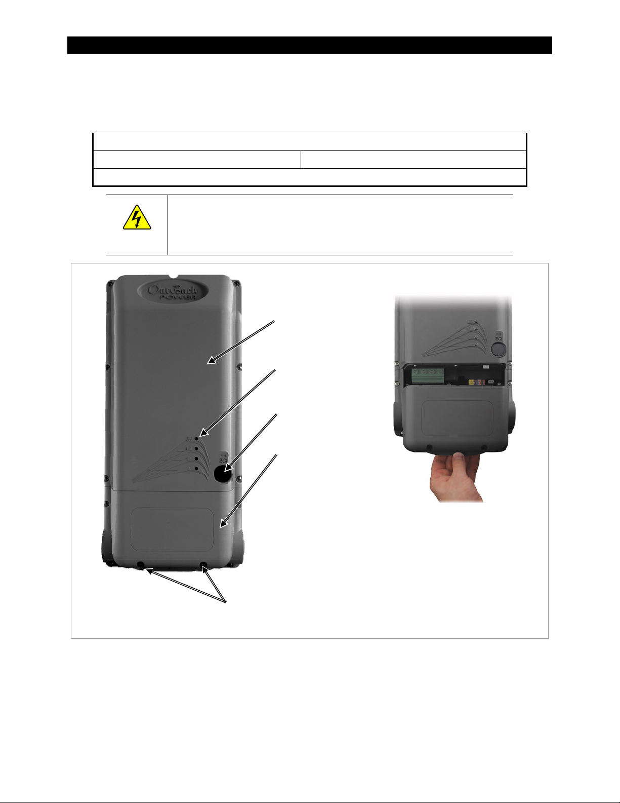
Rainproof
enclosure
Status indicators
with universal symbols
Equalize switch
Easily accessible
wiring
compartment
To remove the wiring compartment cover:
1. Using a Phillips screwdriver, remove the two
screws from the bottom of the compartment
cover. (See above.)
2. Grasp the lower edge as shown. Swing the
Cover screws
cover out while pulling downward.
Figure 1 Features & Wiring Cover
Battery Types
The FLEXmax Extreme charge controller works best with lead-chemistry batteries intended for deep discharge.
These include batteries for marine, golf-cart, and forklift applications. They also include gel-cell batteries and
absorbed glass-mat (AGM) batteries. OutBack Power recommends the use of batteries designed specifically for
renewable energy applications. Lithium-based batteries and other advanced battery technologies may require
special considerations. Please contact OutBack Technical Support at +1.360.618.4363 before implementing
advanced battery technologies.
6 900-0150-01-00 Rev A
Page 9
Installation
Standards and Requirements
All installations must comply with national and local electrical codes. Professional installation is recommended.
A FLEXmax Extreme charge controller operating in unventilated or in other conditions where the ambient
temperature exceeds 45°C (113°F) will have a derated power output. See page 65 for more information.
If damaged or malfunctioning, the FLEXmax Extreme should only be serviced by qualified personnel.
Please contact the local renewable energy dealer/installer for assistance.
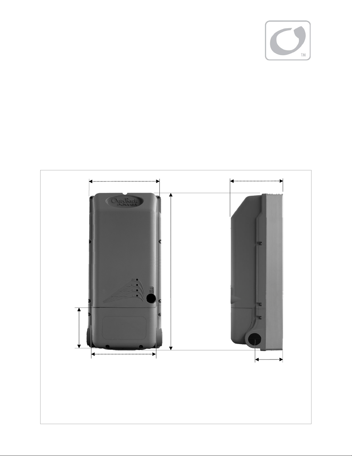
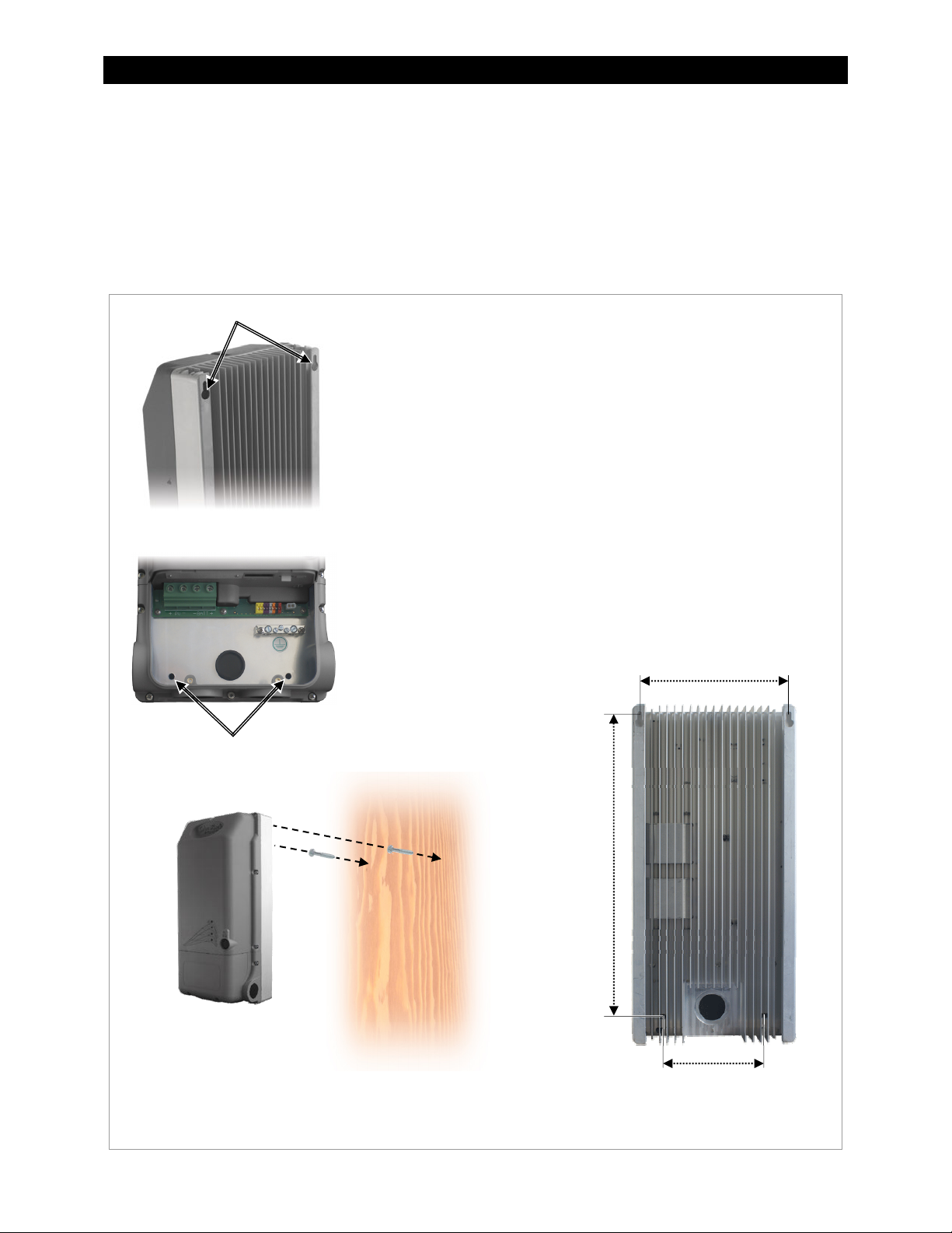
Dimensions
Wiring box
height 4.4”
(11.2 cm)
Width 8.8” (22.4 cm)
Depth 6.0” (15.2 cm)
Height 18.6”
(47.1 cm)
Wiring box opening width 6.9” (17.6 cm)
Side Plugs:
3.27” (8.3 cm)
For height with optional fan installed, see page 10
Bottom Plugs:
3.3” (8.4 cm)
Figure 2 FLEXmax Extreme Dimensions
900-0150-01-00 Rev A 7
Page 10
Installation
Mounting the Charge Controller
The FLEXmax Extreme must be mounted upright on a wall or similar flat upright mounting surface. It must be
mounted at least 36” (91.4 cm) above the ground or floor. No other mounting positions are allowed. Installation
in shade is recommended.
Clearance requirements are a minimum of 6“ (15.2 cm) above and below the controller.
Two mounting methods are available. The first method uses keyhole slots on the back of the controller for
hanging directly on a wall. This method is useful for a standalone installation.
Keyhole slots
To mount using keyhole slots:
1. Use two slotted #14 wood screws. The mounting surface must be
strong enough to support the weight of the FLEXmax Extreme.
NOTE: OutBack is not responsible for damage resulting from
inadequate mounting hardware or preparation.
2. Mark the locations where the screws will be inserted on the surface.
Space them according to the keyhole slot locations (see below).
NOTE: The brackets included with the controller have holes with
the same spacing which can be used as a marking template.
3. Using the appropriate tools, set the screws into the surface
(see below). The heads should protrude by 1/8” (0.3 cm).
4. Hang the FLEXmax Extreme by placing its back against the
mounting surface and aligning the keyhole slots with the screws.
Settle the controller so that the screws are seated in the narrow end
of each slot.
5. Secure the base of the controller to the surface by inserting two ¼”
hex head lag screws into the holes shown to the left.
Slot spacing 7.9” (20.1 cm)
Securing holes
Distance
16.9” (42.9 cm)
Hole spacing 5.5” (13.9 cm)
Mounting is complete. Proceed to charge controller wiring or other installation steps.
Figure 3 Mounting the Charge Controller (keyhole)
8 900-0150-01-00 Rev A
Page 11
Installation
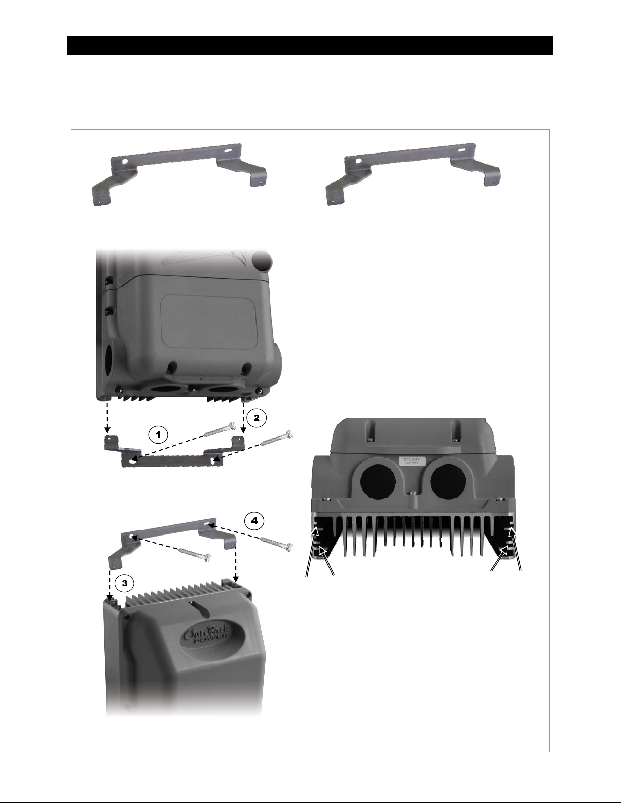
The second mounting method uses brackets on the top and bottom of the controller. This method is useful
when mounting the controller next to an OutBack inverter system, as the conduit openings will align. It is also
useful for mounting without making advance measurements. The FLEXmax Extreme controller comes with two
identical brackets.
To mount using brackets:
1. Using two ¼” hex head lag screws, mount the lower
bracket with the tabs facing upward. The mounting
surface must be strong enough to support the added
weight of the FLEXmax Extreme.
NOTE: OutBack is not responsible for damage
resulting from inadequate mounting preparation.
2. Lower the FLEXmax Extreme onto the bracket as
shown to the left. The bracket tabs can be inserted in
one of two positions: forward or rear.
To mount the controller flush against the wall,
insert the tabs in the forward slots as shown below.
To mount the controller 0.83” (2.1 cm) from the
wall to align with an OutBack mounting plate,
insert the tabs in the rear slots as shown below.
Forward
slot
Rear
slot
NOTE: The charge controller can rest on the lower
bracket for the rest of the procedure, although it will
need at least one hand to steady it.
3. Insert the upper bracket into the same set of slots as
were used with the lower bracket (forward or rear) as
shown to the left.
4. Using two ¼” hex head lag screws, attach the upper
bracket to the mounting surface as shown to the left.
Mounting is complete. Proceed to charge controller
wiring or other installation steps.
Figure 4 Mounting the Charge Controller (brackets)
900-0150-01-00 Rev A 9
Rear
slot
Forward
slot
Page 12
Installation
T
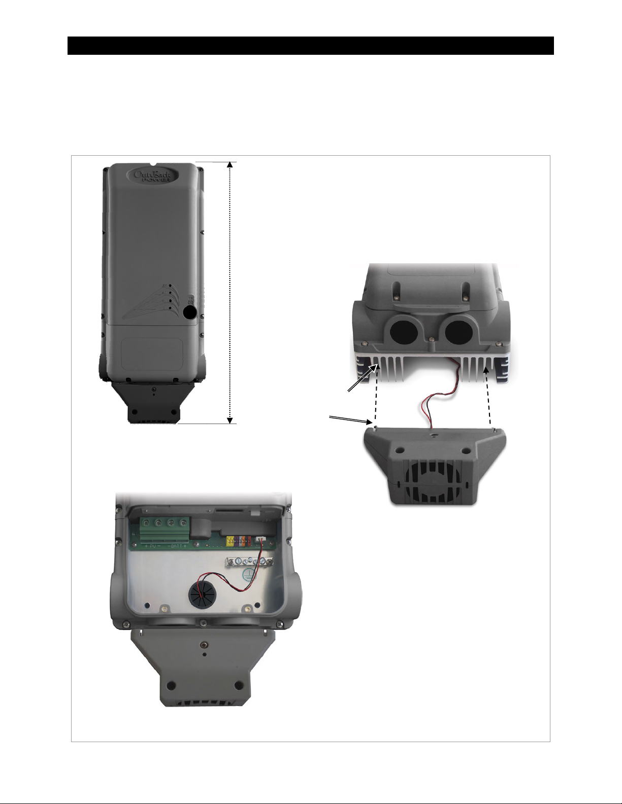
Installing the Fan
An optional fan is available for the FLEXmax Extreme to provide additional cooling. The fan is mounted on the
bottom of the charge controller. The total unit height with the fan attached is shown below. See page 65 for
information on the fan’s effects on unit performance.
To install the optional cooling fan:
1. Place the fan against the base of the FLEXmax Extreme.
he fan is equipped with two locking tabs. Two of the heat sink
fins have holes which receive the tabs. Align the tabs with
these fins (see below).
2. Press the fan straight along the fins until the tabs snap into
the holes.
Height
with fan
22.06” (56 cm)
Heat sink fins
Tab
3. Insert the fan connector into the fan
port in the controller’s wiring box. It
may be necessary to remove the rear
plug and insert a bushing. (See
illustration to the left; also see page 16.)
Installation is complete. The fan will
operate automatically based on the
FLEXmax Extreme internal temperature.
See page 32 to read the temperature using
the MATE3 System Display. This page also
lists the temperatures at which the fan
turns on and off.
Figure 5 Installing the Fan
10 900-0150-01-00 Rev A
Page 13
Installation
p
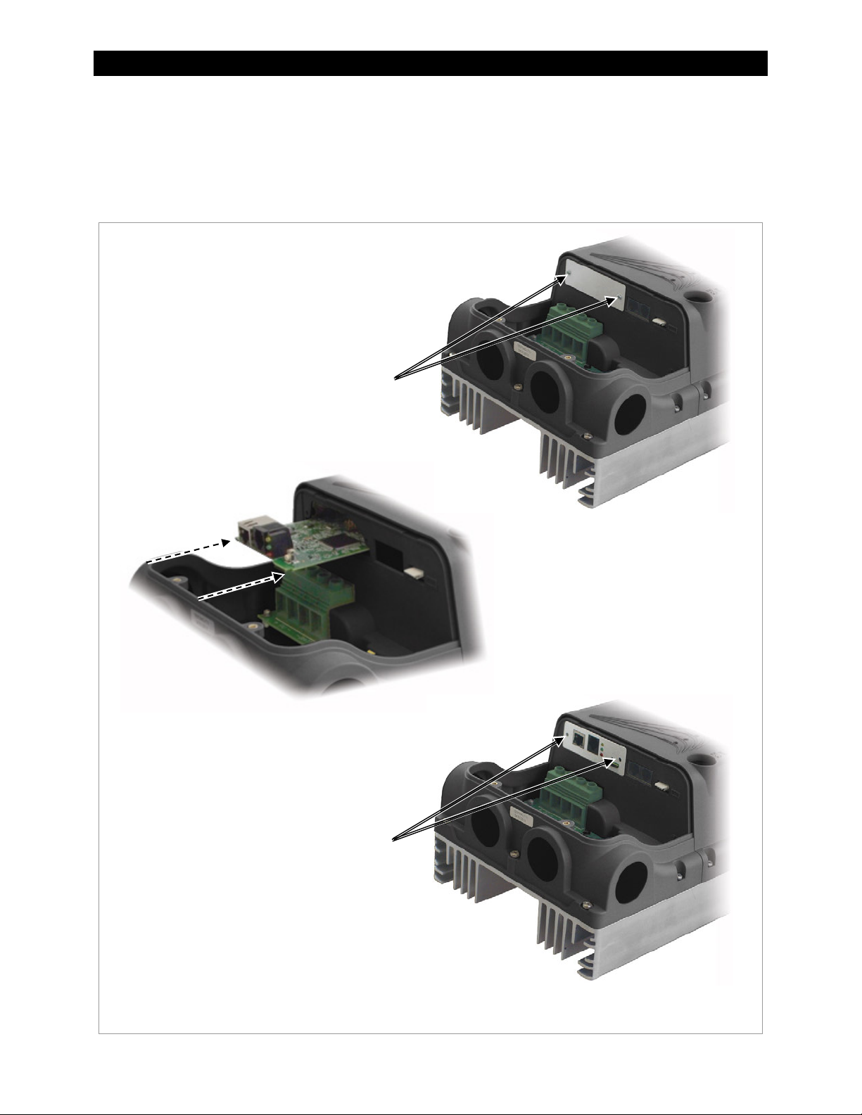
Installing the AXS Card
An optional AXS Card enables Ethernet access to the FLEXmax Extreme using the Modbus protocol. (The AXS
Card is identical in function to the OutBack AXS Port product. See the AXS Port SunSpec Modbus Interface Owner’s
Manual for more information. NOTE: The AXS Port product is not interchangeable with the AXS Card and
cannot be used in this compartment.
To install the AXS Card:
1. Remove the factory-installed blank
compartment cover from the FLEXmax
Extreme. The cover is held in place with
two Phillips screws.
Screws
3. Install the alternate compartment cover
which was included with the AXS Card.
Use the Phillips screws which were
removed from the blank cover.
Insert
Screws
2. Insert the AXS Card onto the rails
on each side of the compartment.
Slide it in until the card presses
firmly onto the connector at the
rear of the com
artment.
Installation is complete. See the AXS Port SunSpec Modbus Interface Owner’s Manual for information on use.
Figure 6 Installing the AXS Card
900-0150-01-00 Rev A 11
Page 14
Installation
Wiring
This section provides instructions on installing PV array wiring into the charge controller. See page 69 for more
notes on PV array sizing. All wiring must comply with local and national codes.
Grounding
This product is intended to be installed as part of a permanently grounded electrical system. This is shown in the
wiring diagrams in this book. Grounding methods must comply with local and national codes.
The FLEXmax Extreme equipment ground is marked with this symbol:
IMPORTANT:
Article 690 of the NEC requires ground-fault protection such as the OutBack GFDI.
It is recommended to bond one of the DC conductors to the ground on the battery
side of the system.
The DC conductor is connected to the ground as a result of installing the OutBack
GFDI. They should not be bonded separately. If a separate bond is already present
in the system, it should be removed. If present, it will defeat the GFDI protection.
(See page 19.)
Bonding the negative and ground is most common. However, the FLEXmax
Extreme can be used normally in either negative-ground or positive-ground
systems. Page 14 shows examples of both types of system wiring. See below for
restrictions on positive grounding. Also see page 74.
CAUTION: Equipment Damage
The FLEXmax Extreme can be used in a positive-ground system when networked with
one OutBack inverter. This requires a HUB Communications Manager. (See page 15.)
It cannot be networked in a positive-ground system with multiple inverters. For use of
the FLEXnet DC Battery Monitor or other devices in these applications, see page 74.
Failure to follow these instructions can damage the controller and other devices. This
damage is not covered under warranty.
The following important restrictions apply unless superseded by local or national codes:
The grounding conductors must be routed separately from all battery conductors.
The battery conductor (positive or negative) must be bonded to the grounding system at only one point.
Wiring Size and Requirements
IMPORTANT:
Wire sizes must comply with local and national codes. Input conductors and circuit
breakers must be rated at 1.56 times the short-circuit current of the PV array (per NEC).
OutBack 100% duty continuous circuit breakers only need to be rated at 1.25 times the
short-circuit current.
Please refer to the NEC and other electrical codes for PV array cable sizing, cable length, and cable ampacity.
Use #4 AWG (25 mm
bar conductors. Smaller cables can reduce performance and possibly damage the unit.
The output can accept up to #2 AWG (35 mm2) wire. Larger conductors will reduce losses and ensure
highest performance of the FLEXmax Extreme.
Install properly sized overcurrent protection devices. The required AIC rating of the device is 4000 Adc.
12 900-0150-01-00 Rev A
2
) wire (minimum) for the output between the FLEXmax Extreme and the battery bus
Page 15
Installation
The largest PV array must have a rated short-circuit current of 64 amps or less under STC (Standard
Test Conditions). The output current limit of the FLEXmax Extreme is 80 amps.
DC battery overcurrent protection must be used as part of the installation. OutBack offers both circuit
breakers and fuses for overcurrent protection.
Physical Requirements and Conduit
IMPORTANT:
Conduit hubs must connect to the conduit before connecting to the FLEXmax Extreme.
WARNING: Burn Hazard
The heat sink can become hot when the charge controller is operating. Use caution
when touching it during operation.
All wire lugs and ground terminals are to be tightened to a torque value of 4 Nm (35 in-lb).
Use copper wiring only. Wiring must be rated at 90°C or higher.
If installing in a wet location, any conduit hubs must comply with the requirements of UL 514B.
Run positive and negative cables side by side.
~ Tie or twist cables together as much as possible to allow the inductive currents to cancel.
~ Ensure paired cables pass through the same knockout and conduit fittings.
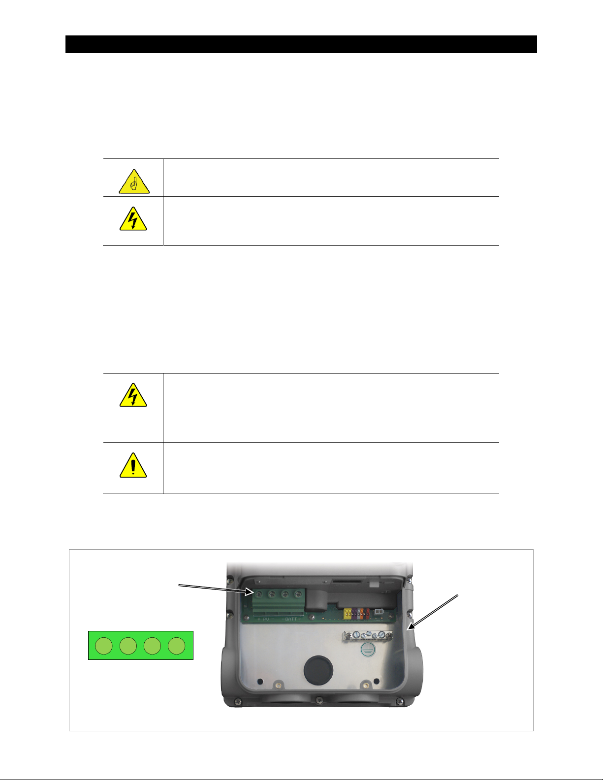
PV and Battery Terminals
WARNING: Shock Hazard
When a PV array is exposed to light, it immediately generates a voltage. Make sure all
DC circuit breakers are OFF (open) BEFORE making any wiring connections. Open both
the battery disconnect devices and the array disconnect devices to ensure isolation of
the controller. Use a DVM to check for voltage on all wires.
CAUTION: Equipment Damage
Each FLEXmax Extreme requires its own PV array. DO NOT PARALLEL PV+ and PVTERMINALS OF MULTIPLE CONTROLLERS ON THE SAME ARRAY!
The negative (-) PV and negative (-) BAT terminals are connected internally. Only one wire is needed to connect
to the negative (-) wire lugs if the negative (-) PV and BAT conductors are bonded at the negative bus bar.
See Figure 8, Figure 10, Figure 16
DC
Terminals
DC TERMINALS
PV + PV - BAT - BAT +
, and Figure 17 for sample wiring diagrams.
Ground
Bus
Figure 7 Wiring Compartment
900-0150-01-00 Rev A 13
Page 16
Installation
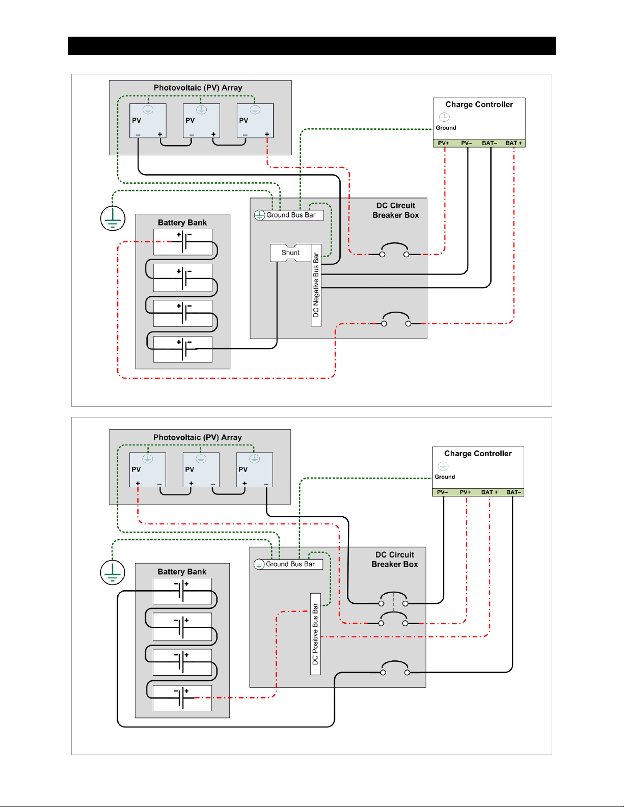
NOTE: Ground Fault and system-specific
wiring not shown
Figure 8 Wiring Diagram – Single Charge Controller with PV Array
NOTE: Ground Fault and system-specific
wiring not shown
Figure 9 Wiring Diagram – Single Charge Controller (Positive-Ground)
14 900-0150-01-00 Rev A
Page 17
Installation
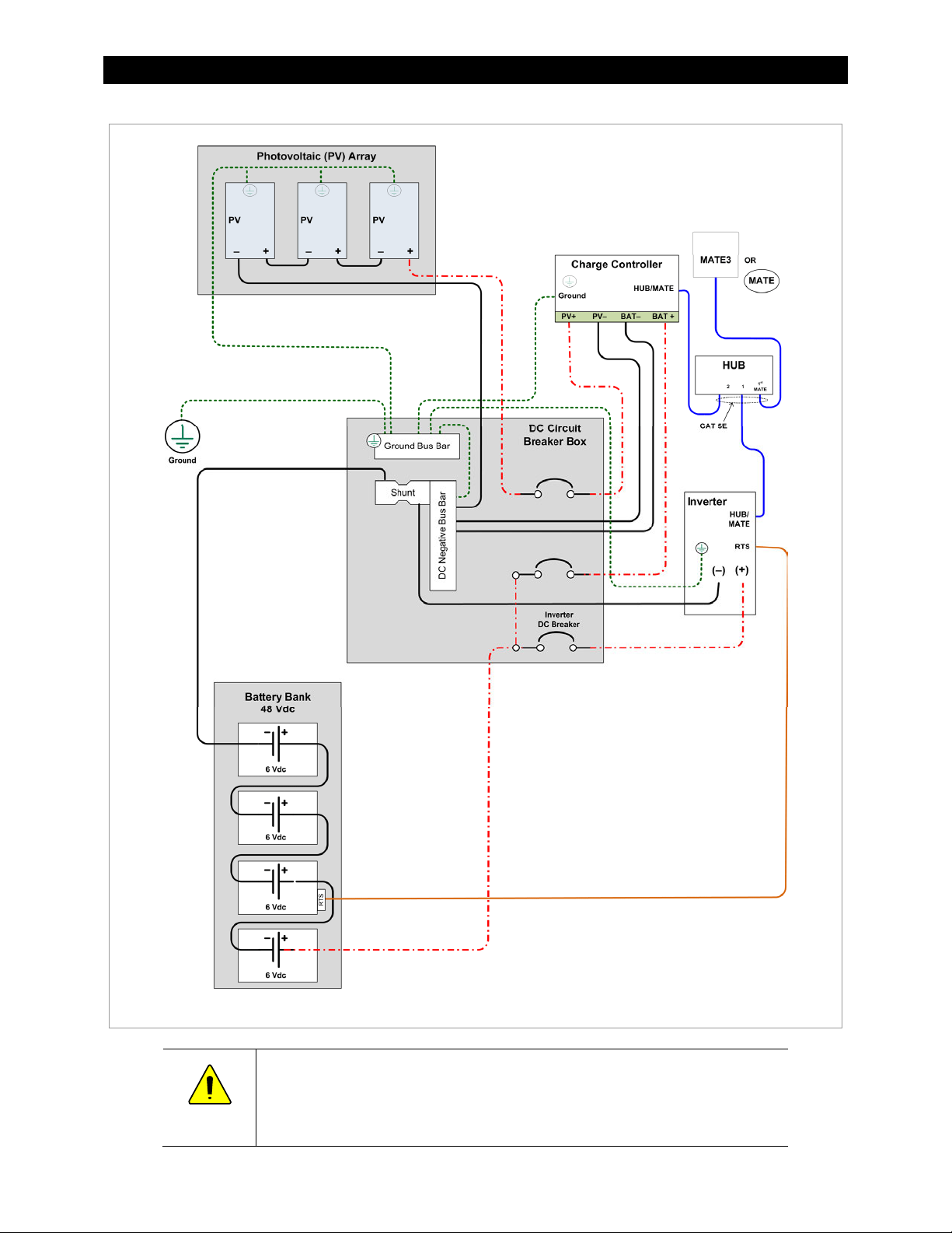
NOTE: Ground Fault and system-specific wiring not shown
Figure 10 Wiring Diagram – Charge Controller with PV Array and Inverter
CAUTION: Equipment Damage
The FLEXmax Extreme can be used in a positive-ground system with one OutBack
inverter as shown above. It cannot be used in a positive-ground system with multiple
OutBack inverters. For other devices or configurations, see page 74.
900-0150-01-00 Rev A 15
Page 18
Installation
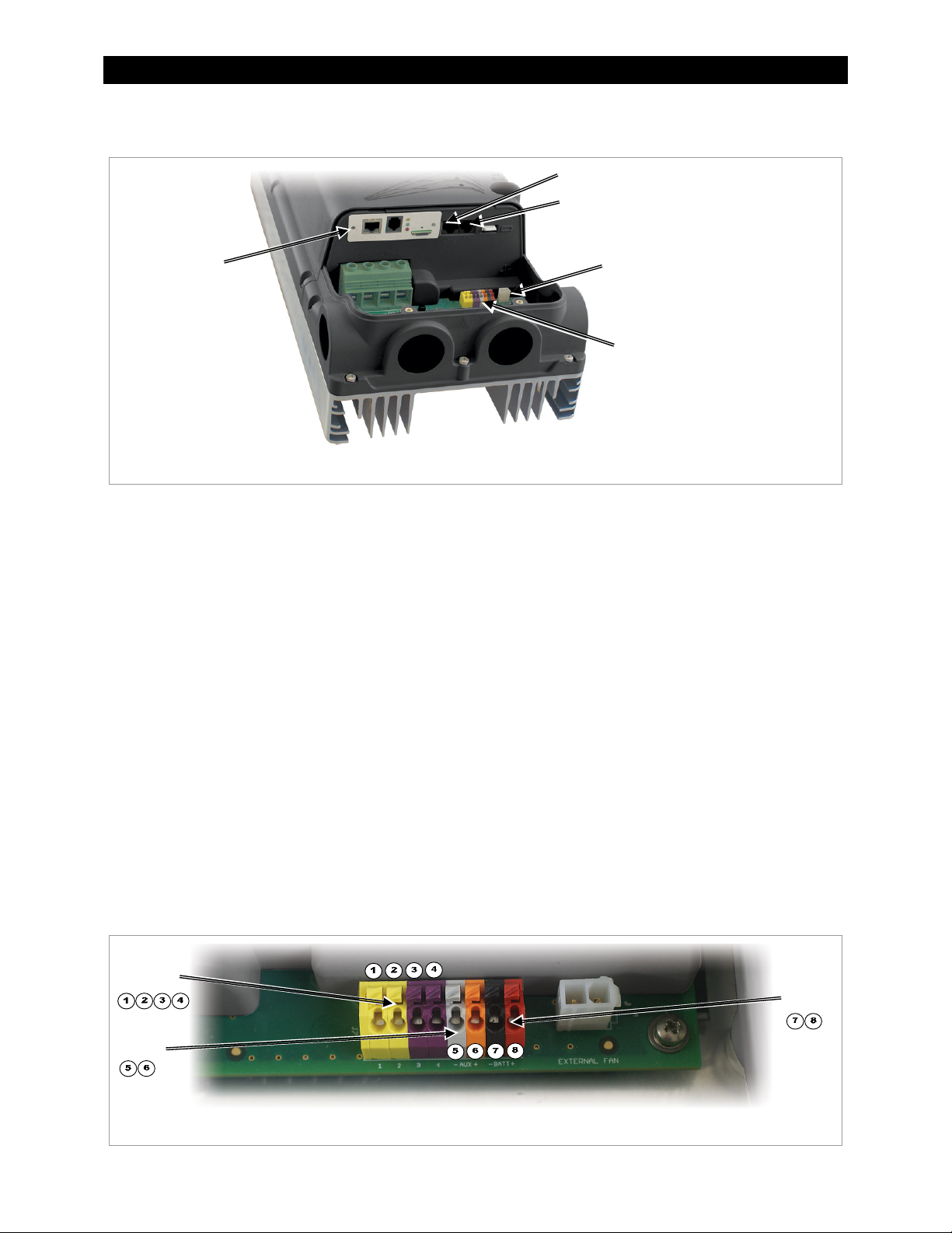
Accessory Terminals and Ports
HUB/System Display Port
Remote
Temperature
Sensor (RTS) Port
AXS Card
(optional)
Fan Connector
Accessory Terminal Block
Figure 11 Wiring Compartment
HUB/Display Port
This is an RJ-45 port for a CAT5 cable to connect OutBack system displays or communications managers. A
ferrite clamp (see page 6) should be installed on this cable inside the compartment.
Remote Temperature Sensor
An optional battery Remote Temperature Sensor (RTS) is recommended for accurate battery charging. A ferrite
clamp (see page 6) should be installed on this cable inside the compartment.
When the system includes an OutBack HUB Communications Manager and a system display, only one RTS is
needed for multiple inverters and charge controllers. Specialized temperature compensation is available.
See page 38 for more information.
AXS Card
This is the location for the AXS Card, which is available as an option for the FLEXmax Extreme. See page 11.
Fan Port
This is the connection for the FLEXmax Extreme cooling fan. See page 10.
Accessory Terminal Block
This block of terminals has connections for the AUX output, for the Battery Sense function, and for the External
Fault function. The terminals accept wire from 16 AWG to 24 AWG.
External
Fault
AUX
Figure 12 Accessory Terminal Block
16 900-0150-01-00 Rev A
Battery
Sense
Page 19
Installation
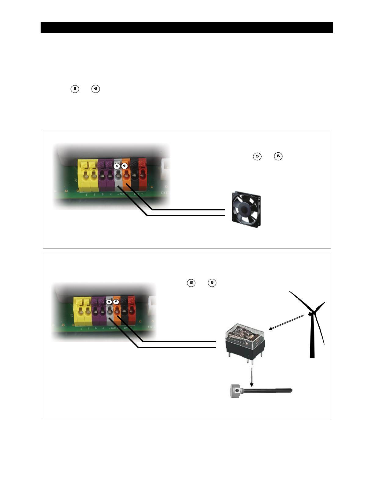
AUX Terminals
The AUX (Auxiliary) output is a small power supply that provides a 12 Vdc output current to an isolated load. The
AUX output can respond to many criteria and control many functions. These include cooling fans, vent fans,
load diversion, fault alarms, and automatic generator control. The AUX can only control one function at a time.
Terminals
and are the + and – terminals for the AUX output. These terminals are colored gray (–) and
brown (+) for easy reference. The terminals can supply up to 250 mA at 12 Vdc (3 W). The AUX circuit contains
electronic overcurrent protection, which resets after being overloaded. No additional fuses are required for the
AUX terminals.
The AUX LED illuminates when the output becomes active. (See page 23 for an illustration of LED indicators.)
In this example, the AUX output directly drives a
12-volt vent fan. The – and + wires on the fan are
connected to terminals
AUX+ terminals.
and , the AUX– and
Figure 13 AUX Vent Fan
In this example, the AUX output drives a relay that
diverts wind power. The relay’s coil is connected to
terminals
terminals. When the AUX output closes the relay
(based on battery voltage), the relay diverts excess
power to a water heating element.
NOTE: Relays and elements shown are examples only and may
vary depending on the installation.
Figure 14 AUX Diversion Control
and , the AUX+ and AUX–
Relay
Element
Turbine
900-0150-01-00 Rev A 17
Page 20
Installation
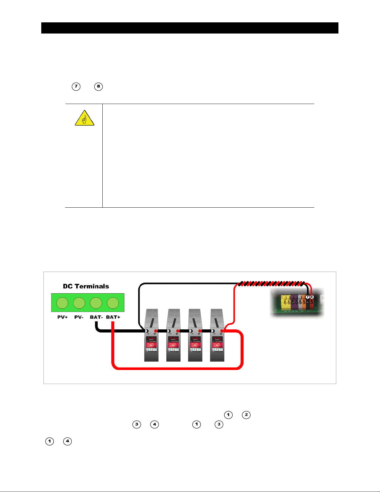
Battery Sense Terminals
The remote Battery Sense terminals are used for accurate voltage monitoring. These terminals connect directly
to the batteries. Using the controller’s main battery cables for voltage sensing is less accurate. This is due to
voltage rise caused by charging currents on the battery conductors.
Terminals
black (-) and red (+) for easy reference. A twisted-pair cable is recommended. (See wire sizing on page 16.)
This function operates automatically when it detects a voltage within 2 volts of the battery voltage reading at
the charge controller’s main terminals. If the reading varies by more than 2 volts, the Battery Sense function is
disabled. The assumption is that the terminals are not connected. (If the terminals are connected, there may be
a wiring problem.)
The MATE3 allows the user to calibrate the battery meter at the charge controller’s main terminals. (See page 45
and the MATE3 manual for more information.) This calibration does not affect the Battery Sense function. If
Battery Sense is in use, calibration changes can be made, but will have no effect until Battery Sense is disabled.
and are the – and + terminals for the Battery Sense function. These terminals are colored
IMPORTANT:
The MATE3 display shows the system voltage as measured at the battery terminals of
various devices. (See Figure 26 on page 29.) This voltage is used for generator starting
and other functions.
If no other devices are present, it will show the reading of the FLEXmax Extreme.
If OutBack inverters are present, the inverter voltage replaces the FLEXmax
Extreme as the system voltage reading.
If the FLEXmax Extreme Battery Sense terminals are in use, this reading replaces
the inverter or the regular charge controller readings as the system voltage.
The FLEXnet DC Battery Monitor is the highest priority and will replace the
Battery Sense reading as the system voltage.
The Battery Sense reading is still shown on the Charge Controller screen. (See Figure 27
on page 30.) This reading is still used to adjust the FLEXmax Extreme charging.
NOTE: Overcurrent protection is
not shown. Recommended
protection for sense conductors is:
Fast-acting device
80 Vdc or greater
1 A or smaller
Cold resistance 10 ohms or less
Figure 15 Battery Voltage Sensing
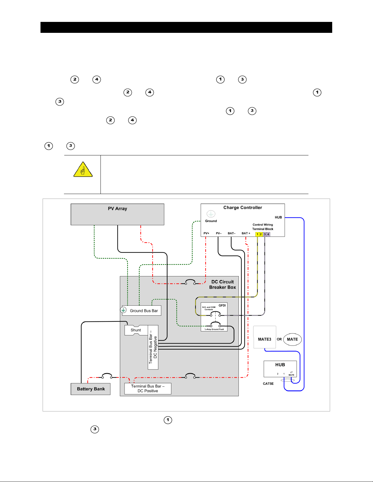
External Fault Terminals
The External Fault terminals are used to make connections to the OutBack Ground Fault Detector/Interruptor
(GFDI) product. A single wire is run from one of the yellow terminals (
from one of the purple terminals (
or ). Terminals and are the most commonly used. These wires
are connected to a normally-open set of contacts on the OutBack GFDI. Figure 16 and Figure 17 show terminals
to without the rest of the control terminal block.
18 900-0150-01-00 Rev A
or ). A second single wire is run
Page 21
Installation
The terminals detect electrical continuity. These contacts remain closed as long as the GFDI bonding switch
remains closed. If a ground-fault event occurs, both the GFDI switch and the GFDI contacts will open. The
External Fault circuit will detect the loss of continuity and will shut down the charge controller.
If multiple charge controllers are in use, they can be paralleled so that all controllers use a common GFDI.
Terminals
and are a parallel set of connections to terminals and .
In the first controller, terminals
and
that it will react accordingly. If a third controller is present, its terminals
connecting to terminals
can be added as needed.
If the terminals are not in use, this function should be disabled. This is performed by directly shorting terminals
on the second controller. This allows the second controller to sense the same conditions as the first so
and with a small jumper wire.
and should have a parallel set of wires which connect to terminals
and should have wires
and on the second controller, and so on. (See Figure 17.) Additional controllers
IMPORTANT:
The FLEXmax Extreme will not function unless either the OutBack GFDI or the
disabling jumper is installed. Initial power-up will result in an External Fault
signal. (See page 61.)
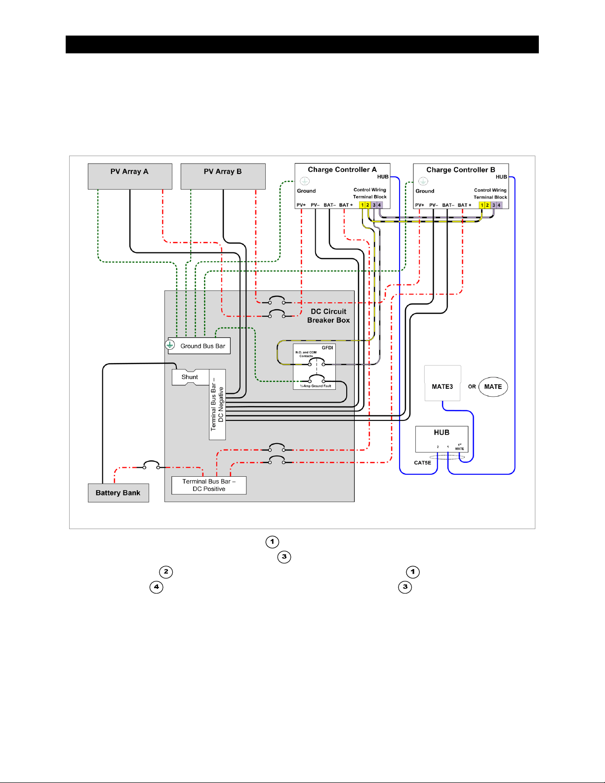
Figure 16 Charge Controller with PV Array Ground Fault Protection
In Figure 16, a wire has been run from terminal to one of the dedicated GFDI terminals. A wire has also been
run from terminal
will read as electrically continuous to the External Fault circuit.
In the event of a ground fault or any other condition which trips the GFDI, these terminals will register loss of
900-0150-01-00 Rev A 19
to the other side of the GFDI. As long as the GFDI remains closed, that pole of the GFDI
Page 22
Installation
continuity. The External Fault circuit will detect this loss immediately and shut down the the controller. The red
Fault LED indicator will illuminate. See pages 24, 32, and 61.
Other possible uses for the External Fault terminals include devices such as arc fault protection, or an Emergency
Power Off (EPO) switch for a fast manual shutdown. Any device with normally open contacts can work with this
function. If more than one device is used, all contacts must be wired in series so that any one device will shut
down the controller.
Figure 17 Two Charge Controllers with PV Array Ground Fault Protection
In Figure 17, a wire has been run from terminal on Charge Controller A to one of the dedicated GFDI
terminals. A wire has also been run from terminal
In addition, Terminal
Similarly, Terminal
places the External Fault circuits on both controllers in parallel.
As long as the GFDI remains closed, that pole of the GFDI will read as electrically continuous to the External Fault
circuit on both controllers. In the event of a ground fault or any other condition which trips the GFDI, these
terminals will register loss of continuity. The External Fault circuit on both controllers will detect this loss
immediately. Both controllers will shut down and display the red Fault LED indicator. See pages 24, 32, and 61.
To reset the controller after an external fault:
1. Remove all sources of power (PV and battery) from the controller.
2. Correct the cause of the fault condition.
3. Follow the power-up procedure on page 21.
20 900-0150-01-00 Rev A
on Charge Controller A has been connected to terminal on Charge Controller B.
on Charge Controller A has been connected to Terminal on Charge Controller B. This
to the other side of the GFDI.
Page 23
Installation
Power Up
IMPORTANT:
The charge controller automatically senses the nominal battery voltage upon
connection. Once set, it retains the nominal voltage setting. Following any type of
shutdown or disconnect, it will return to operation automatically.
The PV array voltage is automatically detected upon connection. The PV array
voltage must never exceed 150 V
It is recommended to restore the FLEXmax Extreme to factory default settings
(see page 45) and reset the nominal voltage (see below) any time the system is
substantially revised or the controller is relocated.
The FLEXmax Extreme uses power from the battery bank to operate. The battery voltage must be at least
10.5 volts or higher to power up the charge controller. When battery power is detected, the charge controller
will flash each of its LED indicators twice in a self-test.
The Status indicator (see page 23) will then flash to show the nominal system voltage that was detected. Each
flash indicates an increment of 12 volts; therefore, one flash = 12 Vdc, two flashes = 24 Vdc, and so on.
.
oc
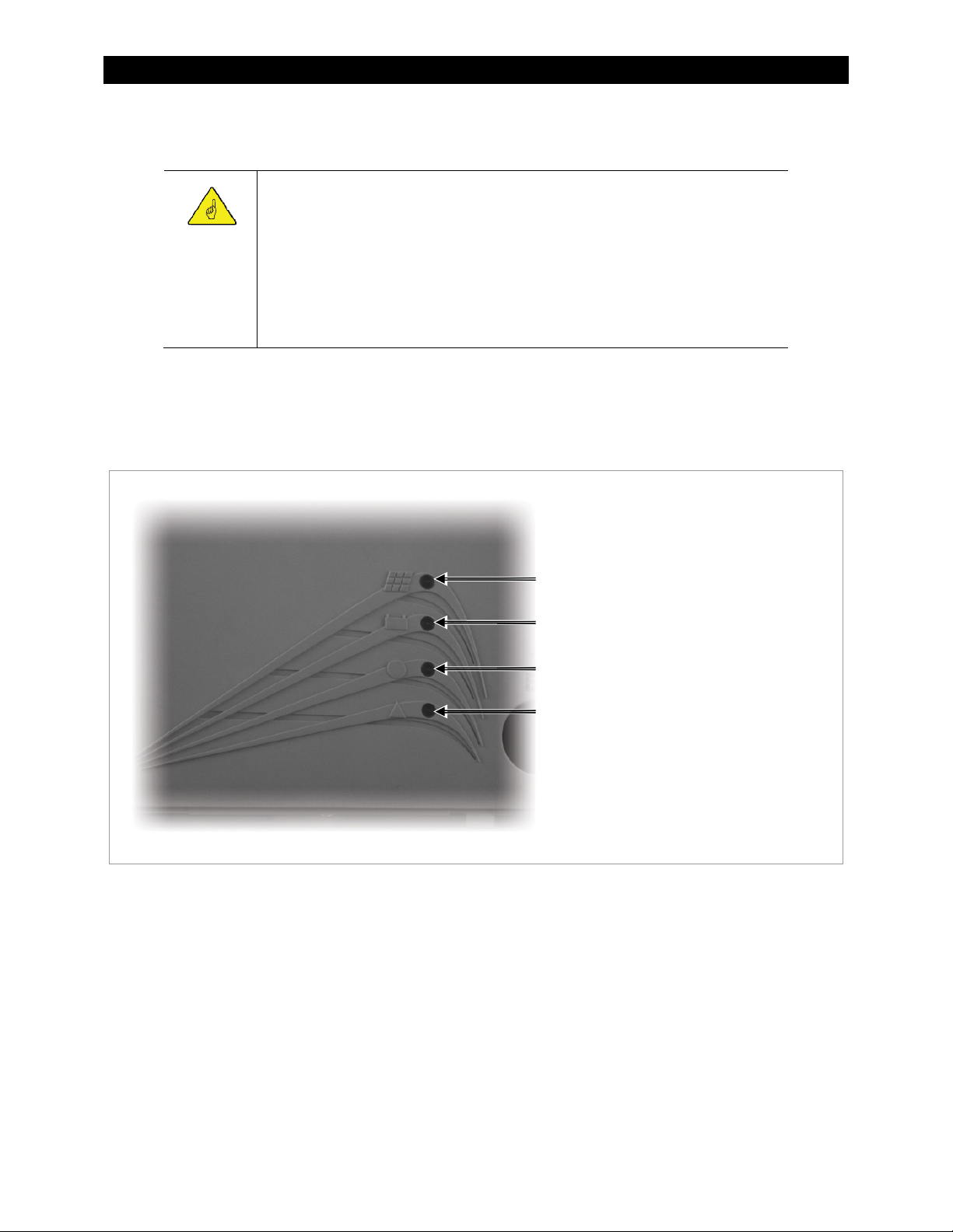
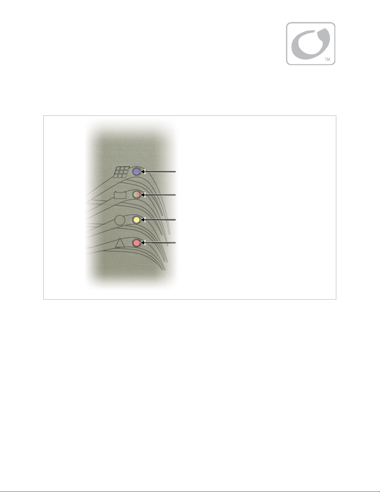
Charging Indicator — Blue LED
Status Indicator — Green/Red (or Amber) LED
AUX Indicator — Yellow LED
Fault Indicator — Red LED
Figure 18 LED Indicators
Setting the Nominal Voltage
Upon initial power-up, the FLEXmax Extreme will sense the battery voltage and use this reading to determine
the nominal system voltage — a battery bank of 12, 24, 36, 48, or 60 volts DC.
The ranges of detection for each nominal battery voltage are:
12-volt system — 10.5 Vdc to 15.7 Vdc
24-volt system — above 15.7 Vdc to 31.4 Vdc
36-volt system — above 31.4 Vdc to 43.2 Vdc
48-volt system — above 43.2 Vdc to 62.8 Vdc
60-volt system — above 62.8 Vdc to 78 Vdc
The batteries must be within the appropriate voltage range for the controller to take the correct reading. A
severely discharged 24-volt battery bank, for example, could read as a 12-volt bank and cause the controller to
900-0150-01-00 Rev A 21
Page 24

Installation
charge inappropriately (or not at all).
Normally the nominal system voltage is retained. If the FLEXmax Extreme is disconnected from the batteries or
otherwise loses power, upon a new power-up it will continue using the nominal voltage and settings
determined previously.
If it is necessary to change the nominal voltage:
1. Reset the FLEXmax Extreme to factory default settings as described below.
2. Remove all sources of power (PV and battery) from the FLEXmax Extreme and then reconnect battery
power. The controller will sense the battery voltage and use this reading to determine the new nominal
system voltage. This will not occur until the power is turned off and then on again.
Resetting to Factory Defaults
The MATE3 system display can be used to reset the FLEXmax Extreme to its factory default settings. See page 45
for more information.
To reset to defaults without using the MATE3:
1. Remove all sources of power (PV and battery) from the FLEXmax Extreme.
2. Press and hold the Equalize switch (see page 6) while reconnecting battery power.
3. Continue holding the Equalize switch. After approximately 10 seconds, the Status indicator will blink
green rapidly. Continue holding the switch until the Status indicator begins blinking amber more slowly.
4. Release the Equalize switch and disconnect the batteries.
Initial Operation
When the PV input circuit breaker is turned on, the FLEXmax Extreme automatically detects the PV input voltage.
It then enters the “Wakeup” state (see page 28) and prepares to charge the batteries by tracking the maximum
power point of the solar array. During the initial tracking, the input PV source is gradually loaded from the
open-circuit voltage (V
power point. The amount of time required before starting operation is dependent on the module type, ambient
temperature, and the amount of sunlight directly on the PV array. Normally, the FLEXmax Extreme starts in the
morning within a few minutes of the PV array being exposed to direct sunlight.
Once the controller begins maximum power point tracking, it will enter a three-stage battery charging cycle.
This cycle can be observed with the controller’s LED indicators. (See page 23.) If the OutBack MATE3 or another
system display is available, it is possible to observe the specific charging stage, mode messages, and readings of
the charge controller.
) to ½ of the Voc. Within this range, the FLEXmax Extreme seeks the maximum
oc
22 900-0150-01-00 Rev A
Page 25
LED Indicators
Status and Information
Charging Indicator — Blue LED
Status Indicator — Green/Red (or Amber) LED
AUX Indicator — Yellow LED
Fault Indicator — Red LED
Figure 19 LED Indicators
The FLEXmax Extreme charge controller has no graphical display. It is equipped with four LED indicators that
show the charge controller’s condition.
The top LED, the Charge indicator, is blue. It illuminates when more than 10 watts of PV power is available.
It is solid when bulk or equalization charging. It flashes when absorption or float charging. The MATE3
system display represents these stages as operating modes in the Status menu. See page 30 for a list of
modes. See page 71 for a description of charging stages.
The Charge indicator will not turn solid if less than 10 watts of PV power is available. It will flash in
constant-voltage charging regardless of how much PV power is available. Note that in some cases it may
illuminate when power is available but the controller is not charging. (See Table 4 on page 28.)
This indicator will flash while performing firmware updates to the FLEXmax Extreme (see page 46).
The second LED down is the Status indicator. It is a tri-color LED which can be red, green, or amber. This
LED is used to indicate either battery voltage or charger status. See Table 2 on page 24.
The following patterns usually indicate particular charging stages.
~ The indicator turns amber (a combination of the red and green colors) if the batteries are equal or
greater than 1.91 volts per cell (Vpc). This often accompanies Bulk or Absorption stage.
~ It turns green upon entering the Float stage. It will remain green regardless of the battery voltage until
it falls below 2.08 Vpc. This will trigger a new charge cycle.
~ It will alternate amber/green during equalization. It can also flash amber/red. (See pages 27 and 72.)
900-0150-01-00 Rev A 23
Page 26
Operation
NOTE: The Status indicator turns red if the battery voltage falls below 1.91 Vpc. The red color shows an urgent
condition, indicating that the batteries are discharged. A red flash means the batteries have fallen below 1.75
Vpc, a critically low voltage. These patterns will appear regardless of the charging stage. If it appears, the Status
indicator cannot show the stage, although it may still be shown by the blue Charge indicator.
IMPORTANT:
The LED indicators do not necessarily tell the amount the controller is actively charging.
The Charge indicator may still indicate Absorption and the Status indicator may indicate
rising battery voltage, even if another charging source is doing most of the work.
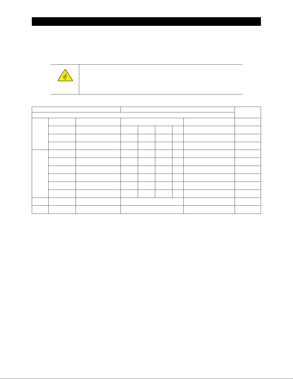
Table 2 LED Indicators
Indicator Controller State
Name Color Pattern Bulk Absorb Float EQ Other
Off Off N/A < 10 W PV available Battery rest
Charge
Status
AUX Yellow Solid (see page 17) Any AUX active
Fault Red Solid N/A External Fault
Blue Solid X X
Blue Flash long (see page 26) X
Blue Flash short (see page 27) X Float
Amber Solid X X ≥ 1.91 Vpc
Green Solid X
Red Solid X X Battery discharge <1.91 Vpc
Red Flash X X Critical battery discharge <1.75 Vpc
Amber/Green Flash (see page 26) X ≤ EQ
Amber/Red Flash (see page 27) X Critical battery discharge <1.75 Vpc
The third LED, the AUX indicator, is yellow. This indicator illuminates when the AUX output becomes active.
Voltage
The fourth (bottom) LED, the Fault indicator, is red. It will turn solid if the charge controller shuts down due
to an External Fault condition. See pages 19 and 20 for more information on the External Fault circuit. If the
MATE3 System Display is present, it will deliver a
Fault Input Active
error message (see page 32).
See Table 7 beginning on page 61 for information on resetting this error.
24 900-0150-01-00 Rev A
Page 27

Operation
Modes of Operation
The FLEXmax Extreme goes through many states during its operation. Figure 20 shows an example of the
various stages of battery charging and several states when the controller is not charging. (The graph in Figure
20 shows a typical day of charging with a nominal 24-volt system. Charging is described in detail on page 71.)
The MATE3 system display has five “mode” messages which represent all states of operation. The following
sections use the names displayed by the MATE3. (See page 30.) These sections describe the controller operation
and show the LED indicators illuminated in each mode.
Figure 20 FLEXmax Extreme Battery Charging and Modes
Bulk
This is a Maximum Power Point Tracking mode which harvests the maximum wattage available from the PV
array. The controller is trying to regulate the battery voltage towards the Absorb Voltage set point. Normally
the charge controller enters this mode at the beginning of the day or when a new charge cycle begins. The
controller may also enter this stage if there is not enough PV energy to maintain a different stage such as
Absorption. See page 26 for more information.
Blue (solid)
Amber (solid)
The Status indicator will remain amber as long as the battery
voltage remains above 1.91 volts per cell (Vpc), even if no
charging is occurring. The Charging indicator, however, will not
illuminate if less than 10 watts is used by the PV. This may occur if
charging is performed by another source.
Figure 21 LED Indicators (Bulk)
900-0150-01-00 Rev A 25
Page 28

Operation
Absorb
The MATE3 displays this message for the Absorption stage of a three-stage cycle. In this stage, the FLEXmax
Extreme regulates the battery voltage at the Absorb Voltage set point. Absorption is a constant-voltage,
variable-current charging stage. It usually involves a tapering current flow. However, it may deliver no current
and still display Absorb if another source maintains the batteries above the Absorb Voltage set point.
While the batteries are held at this voltage, the internal timer counts up from zero toward the Absorb time
setting. (See pages 30, 36, and 71.) The charger will exit this stage and enter the Float stage if the timer reaches
the time limit, or if the Absorb End Amps setting is reached. (See page 36.)
The absorption timer is internal to the FLEXmax Extreme and is not displayed as a real-time reading. However,
the Absorb reading shown on page 30 will display the total time spent in Absorption that day.
Blue (flash on 2 seconds, off ½ second)
Amber (solid)
Both indicators will remain in these states as long as the
battery voltage remains above 1.91 volts per cell (Vpc),
even if no charging is occurring. This may occur if
charging is performed by another source.
If the battery voltage drops below the Absorb Voltage set point (see page 36), the FLEXmax Extreme reverts
back to the Bulk charge stage. The MATE3 displays Bulk as shown on page 25.
The internal timer may not always begin at zero if the last charge was interrupted or ended early. If the batteries
drop below the voltages noted on Table 3, the timer will begin counting down toward zero. This adds to the
duration of the next Absorption stage. If the timer reaches zero, it will last for the full duration of the Absorb
time setting (see page 36).
Lower voltages will cause the timer to subtract minutes at a faster rate, as shown on Table 3. These voltages
indicate a significantly greater battery discharge, requiring a much longer charge cycle.
Table 3 Absorption Timer
Battery Voltage Timer Activity
Figure 22 LED Indicators (Absorb)
12.4 V, 24.8 V, 37.2 V, 49.6 V, or 62.0 V, and
less than the Absorbing voltage
<12.4 V, 24.8 V, 37.2 V, 49.6 V, or 62.0 V For every minute elapsed, 1 minute is subtracted
<12.0 V, 24.0 V, 36.0 V, 48.0 V, or 60.0 V For every minute elapsed, 2 minutes is subtracted
No change.
from the timer
from the timer
< 11.6 V, 23.2 V, 34.8 V, 46.6 V, or 58.0 V For every minute elapsed, 4 minutes is subtracted
from the timer.
26 900-0150-01-00 Rev A
Page 29

Operation
Floating
The MATE3 displays this message for the Float stage of a three-stage charging cycle. In this stage, the FLEXmax
Extreme regulates the battery voltage at the Float Voltage set point. This stage is temperature-compensated.
(See page 72.) Float is a constant-voltage, variable-current charging stage. It usually involves a minimal
(maintenance) current flow. However, it may deliver no current and still display Float if another source
maintains the batteries above the Float Voltage.
If the battery voltage drops below the Float Voltage, the FLEXmax Extreme will employ the MPPT function to
draw more power from the PV array. (This may occur if the batteries are powering loads.) If this occurs, the
operation may change to constant-current, variable-voltage. The mode will still show Float.
Blue (flash on ½ second, off 2 seconds)
Green (solid)
This indicator will remain green if the voltage rises
or drops, unless it decreases below 2.08 Vpc. This
will trigger a new charge cycle.
Figure 23 LED Indicators (Float)
EQ
The MATE3 displays this message if the charger is in a cycle of equalization. (See page 72 for an explanation of
equalization.)
Before equalizing, battery loads should be turned off and the battery should be charged so the charge controller
can quickly reach the Equalization Voltage set point. (See page 38.) Otherwise, the charge controller may have
difficulty reaching or maintaining the equalization process.
Equalization is not battery temperature compensated.
Blue (solid)
Amber/green (alternating once per second)
This indicator will alternate amber and red if the batteries
are below 1.75 volts per cell (Vpc) while equalizing. This is
usually a temporary condition.
Figure 24 LED Indicators (Equalization)
900-0150-01-00 Rev A 27
Page 30

Operation
Silent
The MATE3 displays the operating mode as Silent if the charge controller has stopped charging. This message
represents a variety of conditions, many of which are common. For example, Silent is shown at night or any
period of insufficient light. Table 4 lists the indicators and the PV open-circuit voltage which show specific Silent
conditions. In these cases, no indicators will be illuminated.
However, Silent may also appear in the event of an error shutdown. If the mode is Silent and the red Fault
indicator is illuminated, an External Fault may have occurred. See pages 19, 20, and 61.
Red (solid)
Figure 25 LED Indicators (Fault)
Table 4 Reasons for Silent Mode
Charge LED Status LED Fault LED Voc Other
No PV energy or “Sleep” mode. If the V
Below battery
No No No
Above battery
Intermittent Any No Above battery
battery voltage, the controller is “sleeping”. This is
normal at night. The threshold for Sleep mode is
settable. See page 37.
Low light or “Snooze” mode. V
voltage but not enough array current is available for
charging. This is normal in the morning, evening, or in
heavy clouds (low light). The threshold for Snooze
mode is settable. See page 37.
“Wakeup” mode. The controller has detected more than
the required 10 watts, but has not yet begun charging.
This condition only lasts a short time. The blue Charge
indicator may turn on and off briefly while the controller
is performing initial power tracking. This can also occur
if PV conditions change and the controller has to
calculate a new power point.
If continuous, this behavior may also indicate an
“unloaded output” condition where the batteries have
been disconnected from the charge controller.
is less than
oc
is greater than battery
oc
28 900-0150-01-00 Rev A
Page 31

MATE3 System Display and Controller
Battery Status Indicators (x3)
Charger Indicator
Operation
Charge Controller Soft Key
Figure 26 Display and LED Status Indicators
The MATE3 System Display and Controller is a display which allows the user to read the operating mode,
measurements, and any status messages from the FLEXmax Extreme charge controller. It can also change the
charge controller’s settings when the default settings are not enough.
.
80%
State of Charge (SOC).
Battery Status Indicators
Three LED indicators provide a visual reference to indicate the condition of the battery bank.
A GREEN LED means the batteries have an adequate charge at that time. It does not always mean they are
full. If the FLEXnet DC battery monitor is installed, this means the batteries are
A YELLOW LED means the batteries are somewhat discharged. If the FLEXnet DC is installed, this means the
batteries are
A RED LED means the batteries are greatly discharged and may require attention. If the FLEXnet DC is
installed, this means the batteries are
60%
and
70%
.
< 60%
Table 5 Battery Status LED Indicators
Color 12 Vdc Unit
GREEN 12.5 Vdc or higher 25.0 Vdc or higher 37.5 Vdc or higher 50.0 Vdc or higher ACCEPTABLE
YELLOW 11.5 to 12.4 Vdc 23.0 to 24.8 Vdc 34.5 to 37.2 Vdc 46.0 to 49.6 Vdc MARGINAL
RED 11.4 Vdc or lower 22.8 Vdc or lower 34.2 Vdc or lower 45.6 Vdc or lower LOW
NOTES:
Gaps in the table (higher-voltage units) are due to the resolution of the charge controller’s DC meter.
The Battery LED settings cannot be changed.
Voltages higher than shown in the GREEN row usually means that the batteries are charging.
24 Vdc Unit,
± 0.2 Vdc
36 Vdc Unit,
± 0.3 Vdc
48 Vdc Unit,
± 0.4 Vdc
Battery Status
Charger Indicator
The MATE3 is equipped with several LED indicators denoting status. The Charger indicator (see Figure 26) will
illuminate if the charge controller is delivering more than a minimal amount of charging power to the batteries.
It will flash if the charge controller is equalizing the batteries.
NOTE: The Charger indicator will illuminate for any device on the HUB Communications Manager that is
charging, including OutBack inverters. If a FLEXmax Extreme charge controller is accompanied by other devices,
this indicator may indicate charging by any device, not just that controller.
900-0150-01-00 Rev A 29
Page 32

Operation
A
Charge Controller Soft Key
The MATE3 is equipped with a series of “soft” keys with varying functions. From the Home screen, the far left key
is designated as the Charge Controller soft key any time a charge controller is connected. Pressing it will enter
the Status menu for the charge controller. (See page 30.)
Status Screen
Modes of Operation:
Bulk
Absorb
Float
EQ
Silent
See page 25 for a description of modes.
See page 71 for a description of battery
charging.
Soft Keys:
<Next> brings up a series of screens with
current statistics, totals, and other data. The
internal temperatures and any fault messages
are also displayed here. These screens are all
shown beginning on page 31.
<Graph> brings up a series of screens that
plot various charge controller information
over time. The graphs include inverter and
charger wattage, power imported from an AC
source, battery voltage, and others. These
screens are all shown beginning on page 34.
<Port> cycles through each device
connected to the network. If more than one
charge controller is installed in the system,
pressing the <Port> soft key will cycle
through each controller.
<Back> returns to the previous screen.
Figure 27 Charge Controller Soft Key Screens
Screen Items:
The upper left corner of the screen shows the FLEXmax charge
controller’s current mode of operation. Bulk is shown in this
illustration.
In displays the present PV array operating voltage and the
current being harvested from the array.
VOC displays the open-circuit voltage available from the PV.
Out displays the present battery voltage and the current
being delivered from the charge controller(s) to charge the
battery bank. To the right, this line displays the number of
kilowatt-hours and amp-hours accumulated that day.
Operating displays the total hours the charger has operated
that day in any stage.
Float displays the amount of time the controller has been in
the Float stage.
bsorb displays the amount of time the controller has been in
the Absorbing stage. The maximum duration is the Absorb
time setting. (See pages 26, 36, and 71.)
Maximum displays the maximum amperage and wattage
harvested from the PV array that day, and the time both were
recorded.
The lower right corner shows the current status of the charge
controller’s Auxiliary (AUX) output. (See page 39.)
NOTE: If the FLEXmax Extreme shuts down due to a fault condition, the MATE3 status messages do not indicate
the cause. The MATE3 will display the status as Silent. However, the Error screen (see page 32) will show the
cause if it is one of the defined errors on that screen. The MATE3 will show an Event in the appropriate menu.
(See the MATE3 manual for more information.).
See page 61 for additional information on troubleshooting Error conditions and faults.
30 900-0150-01-00 Rev A
Page 33

Operation
Stats Screen
From the Charge Controller screen, the <Next> soft key proceeds to the Charge Controller Stats screen. This
screen shows data which has been accumulated since the system went online, or since the last reset.
Screen Items:
The items under Maximum are not incremental.
They are updated only if a higher value is measured.
VOC displays the highest measured V
the VOC reading on page 30 for the current Voc.)
Battery displays the highest measured battery
voltage. (See the
current battery voltage.)
Wattage displays the highest measured wattage
harvested from the PV. (See the
page 30 for the current wattage. See the
reading for the highest wattage that day.)
Out
reading on page 30 for the
oc
Out
reading on
value. (See
Maximum
Soft Keys:
<Next> proceeds to the Error, Datalog, and Temps screens
(see pages 32 and 33).
<Reset> proceeds to the Reset screens for the items under
Maximum and Total. (See Figure 29.)
<Back> returns to the previous screen.
<Port> cycles through each device connected to the network.
Figure 28 Stats Screen
Screen Items:
The Reset screens allow the items in the Stats screen to be reset to
zero. The Yes soft key is used for resetting. The items under
Maximum and Total can be reset independently. Until then, they
will continue to register higher numbers or greater accumulations.
Soft Keys:
<Maximums> proceeds to the Reset screen for the Maximum
statistics (see Figure 28).
<Totals> proceeds to the Reset screen for the Total.statistics (see
Figure 28.)
<Back> returns to the previous screen.
<Port> cycles through each device connected to the network.
<No> returns to the previous screen without resetting.
<Yes> proceeds to a
confirmation screen after
resetting the item (see
example to the right).
<Continue> returns
to the Charge Controller
Stats screen.
The items under Total are incremental. These items
are updated daily with higher totals.
displays a historical accumulation of the
kWh
kilowatt-hours harvested by the controller. (See the
Out
reading on page 30 for the daily accumulation.)
kAh displays a historical accumulation of the
kiloamp-hours used to charge the batteries. (See the
Out
reading on page 30 for the daily accumulation.)
Figure 29 Stats Reset Screens
900-0150-01-00 Rev A 31
Page 34

Operation
f
T
Error Screen
From the Charge Controller Stats screen, the <Next> soft key proceeds to the Charge Controller Error screen.
This screen displays fault conditions for the FLEXmax Extreme. If an item displays Y, the error is active. Some
errors accompany a controller shutdown; others simply report status.
Screen Items:
has exceeded 145 Vdc and has
oc
One of the two internal temperature
Soft Keys:
<DataLog> proceeds to the Datalog screen
(see page 33).
<Temps> proceeds to the Temps screen (see
Figure 31.)
<Back> returns to the previous screen.
<Port> cycles through each device connected
to the network.
VOC Too High The PV array V
shut down. This error can clear automatically. (See the
Troubleshooting guide on page 61.)
Over Temperature The FLEXmax Extreme is too hot to operate
and has shut down. This error can clear automatically. (See the
Troubleshooting guide on page 61. Also see the temperature
readings in Figure 31.)
Shorted RTS The Remote Temperature Sensor (RTS) has
malfunctioned. This error will not shut down the controller, but
the controller cannot compensate for temperature while the
error is present. (See the Troubleshooting guide on page 61.)
Fault Input Active
open circuit. The controller has shut down. This is the only error
in this menu that illuminates the Fault indicator (see page 24).
This error requires a manual reset. See pages 18 and 19. This
error can also occur from an “Overcurrent” condition. (See the
Troubleshooting guide on page 61.)
Reduced Performance
sensors (see below) has failed. If a failure is detected, the
FLEXmax Extreme will operate with a maximum output current
of 20 Adc.
he External Fault terminals have detected an
Figure 30 Error Screen
Temps Screen
From the Charge Controller Error screen, the <Next> soft key proceeds to the Charge Controller Temps screen.
This screen shows internal temperatures as measured at several locations in the controller. These measurements
are used for fan control, temperature derating, or to trigger a shutdown in extremely hot temperatures. If any of
these events occur, this screen can be used to check the temperatures.
Screen Items:
Output FETs The internal temperature as measured on the
controllers’s Field Effect Transistor (FET) heatsink.
Enclosure The internal temperature as measured on the
controller’s housing.
The list below shows the readings at which the FLEXmax
Soft Keys:
<Back> returns to the previous screen.
<Port> cycles through each device connected to
the network.
Figure 31 Temps Screen
Extreme performs certain functions. See pages 10, 61, and 65.
Event Output FETs Enclosure
Over Temp error 130 78
Output derates 86 73
Fan turns on 76 72
Fan turns of
61 67
32 900-0150-01-00 Rev A
Page 35

Operation
A
DataLog Screen
From the Charge Controller Error screen, the <DataLog> soft key proceeds to the Charge Controller Datalog
screen. This screen shows accumulated daily amp-hour and watt-hour statistics, as well as maximum current,
wattage, and maximum and minimum voltage figures. These maintain a continuous daily log, up to 128 days,
which can be recalled. One day can be displayed at a time.
IMPORTANT:
If two or more charge controllers are used in the same system and are started or cleared
on different days, their numeric dates will not be the same. This can lead to some
misunderstandings when looking back and comparing data between the two or more
units. A user looking back at day 12 on both units would find very different results.
Screen Items:
Current
Date
The upper left corner shows the date of the
selected Datalog screen. (The current Datalog
screen reads "Today.") To the right, this line also
displays the kilowatt-hours and amp-hours
accumulated that day.
Soft Keys:
<+Day> advances the display forward by a single
day. If the display reads “Today”, it does nothing.
<–Day> advances the display backward by a single
day and will display the selected date.
<Back> returns to the previous screen.
<Port> cycles through each device connected to
the network.
Figure 32 DataLog Screen
Max Output displays the maximum current and
wattage recorded that day. (See the Maximum
reading on page 30.)
bsorb The amount of time the Absorbing
timer ran that day. (See the
page 30.)
Float The amount of time the Float timer ran
that day. (See the
High VOC
voltage (V
Min Batt
recorded that day.
Max Batt
recorded that day.
displays the lowest battery voltage
displays the highest battery voltage
Float
displays the highest open-circuit
) recorded that day.
oc
Absorb
timer on
timer on page 30.)
900-0150-01-00 Rev A 33
Page 36

Operation
T
Graph Screens
The <Graph> soft key brings up the following screens which plot various types of data over time. The first
screen shows changes in PV wattage over time.
his axis shows date and time
in 6-hour increments.
This axis shows
PV wattage.
Figure 33 Output Graph
The <Next> soft key brings up a screen showing changes in battery voltage over time.
This axis shows date and time
in 6-hour increments.
This axis shows
battery voltage.
Figure 34 Battery Graph
The <Next> soft key brings up a screen showing changes in PV voltage over time.
This axis shows date and time
in 6-hour increments.
This axis shows
PV voltage.
Figure 35 PV Graph
Continuing to press the <Next> soft key will proceed through the same graphs again from the beginning.
34 900-0150-01-00 Rev A
Page 37

Programming the FLEXmax Extreme
Menu Structure in the MATE3
Figure 36 shows the MATE3 menu structure for adjusting the charge controller settings.
The Main Menu shown below is accessed with the LOCK button and a password. Use the MATE3’s control
wheel to move up and down between menus (or options within a menu). Use the center button on the control
wheel to make a selection. (See the MATE3 manual for more information.)
Some menus may not be accessible if the user access levels are restricted.
Figure 36 Menu Structure
900-0150-01-00 Rev A 35
Page 38

MATE3 Screens
T
Charge Controller Settings
Charge Controller menu options include the following:
Charger
MPP
Temperature Compensation
Battery Equalize
Grid-Tie Mode
Auxiliary Output
Restart Mode
Calibrate
Reset Charge Controller to Factory Defaults
Charger
-------------------------------------------------------------- >
----------------------------------------------------------------- >
---------------------------------- >
-------------------------------------------------- >
---------------------------------------------------- >
-------------------------------------------------- >
------------------------------------------------------ >
------------------------------------------------------------ >
------------ >
See below.
See page 37
See page 38.
See page 38.
See page 38.
See page 39.
See page 45.
See page 45.
See page 45.
IMPORTANT:
Battery charger settings need to be correct for a given battery type. Always follow
battery manufacturer recommendations. Making incorrect settings, or leaving them at
factory default settings, may cause the batteries to be undercharged or overcharged.
An appropriate circuit breaker, or overcurrent device, must be used between the
battery and the charge controller.
If a battery remote temperature sensor (RTS) is used, set the Absorb and Float setting
voltage based on a 25°C/77°F setting.
The charge controller uses a “three-stage” battery charging cycle which utilizes multiple settings. This menu
controls the voltages and timers for the battery charger. See page 71 for an explanation of the three-stage cycle
and a description of individual stages. See page 25 to see what indicators and messages appear at each stage.
Set Points:
Absorb Voltage – Target voltage for bulk stage. Utilizes
constant-current charging.
(Absorb) Time – Amount of time held at Absorb voltage.
Utilizes constant-voltage charging.
Float Voltage – Final stage after completion of charge.
Utilizes constant-voltage charging.
Rebulk Voltage – Low voltage trigger for new charge.
Current Limit – Maximum DC amps from that controller.
Absorb End Amps – Low current that indicates completed
charging. It triggers Float stage regardless of Absorb time.
Figure 37 Charger
Absorb Time
When the
. When the battery voltage drops below the
Float
to MPP operation to draw more PV energy to maintain this set point.
36 900-0150-01-00 Rev A
is adjustable from 0 to 24 hours (consult the battery manufacturer’s recommendations).
Absorb Time
is reached, the charge controller goes into Float stage and the MATE3 will display
Float Voltage
set point, the charge controller will return
Page 39

MATE3 Screens
MPPT
The charge controller uses a maximum power point tracking (MPPT) algorithm which manipulates the output of
the PV array to harvest maximum wattage. Although this function is automatic, this menu allows the user to
adjust many of its parameters for special applications. See page 73.
Set Points:
MPPT Mode – Selects between Auto (which allows
automatic MPPT) and U-Pick (which limits the maximum
power point tracking to a specified voltage).
U-Pick VOC% – The percentage of the open-circuit voltage
(V
) used as the MPP tracking limit in U-Pick mode.
oc
Wakeup VOC Change VDC – The change in V
bring the controller out of “Sleep” or “Snooze” operation
regardless of Change Time. The controller will enter MPPT.
(The change in V
(Wakeup VOC) Change Time – The timer setting to leave
”Sleep” or ”Snooze” operation regardless of Change VDC.
The controller will enter MPPT. (It may re-enter “Snooze”
and restart the timer if no power is available).
Snooze Mode Amps – The output current limit below which
the controller enters “Snooze” due to inactivity.
MPP Range Minimum – Adjusts the lower limit of the
controller’s tracking algorithm. This can narrow the focus of
the initial tracking process.
MPP Range Maximum – Sets the upper limit of the tracking
algorithm as a percentage of the V
means that power may be available).
oc
.
oc
which will
oc
Figure 38 MPPT
The MPPT Modes perform the following functions:
Auto Track
Mode
U-Pick
voltage (V
The Wakeup settings adjust the V
(default) automatically measures the PV upon wakeup and then tracks the array MPP. If
Restart
is set to 1 or 2, the controller awakens every 1.5 hours and does an initial tracking. (See page 70.)
allows the user to manually adjust the MPP tracking limit as a percentage of the array's open-circuit
oc
).
U-Pick %
acquires a new Voc value every 1.5 hours if
conditions that cause the charge controller to wake up during “Sleep” or
oc
Auto Restart
is set to 1 or 2.
“Snooze” operation. (See Table 3 on page 26.) Both settings may help adjust for varying conditions. Since
environmental conditions impact the open-circuit voltage of an array, the Wakeup VOC Change VDC can be
based on the last measured V
value.
oc
Before changing these values, monitor the system for a week or so using the factory defaults and then gradually
adjust the set points. If the set points are set too high, the charge controller might not wake up soon enough or
often enough, which means a loss of power production.
The Mpp Range settings adjust the upper range limit of the charge controller’s maximum power point (MPP)
tracking.
The default
MPP voltage limit is set at 90% of the V
Max
array. If necessary, the adjustable limits are 80%, 85%, 90%, and 99% of the V
optimizes the tracking window for MPPT. The default setting of
Min
window as one-half the V
.
oc
and should not normally be adjusted for a PV
oc
.
oc
establishes the lower limit of this
Half
The Min range limit setting may be set to FULL if something other than a PV array is connected to the input of
the charge controller, such as a hydroelectric turbine (see page 73). However, the input voltage must never
exceed 150 Vdc at any time.
900-0150-01-00 Rev A 37
Page 40

MATE3 Screens
Temperature Compensation
The Temperature Compensation screen allows the user to control the Absorbing and Float voltage limits during
charging when using a Remote Temperature Sensor (RTS). The RTS adjusts charging voltage depending on
battery temperature. See page 72 for an explanation of compensation.
Set Points:
Mode – Selects between Limited (which uses the upper and
lower voltage settings below) and Wide (which uses the
entire range of compensation).
Slope – The amount of temperature compensation. This is
measured in millivolts per degree C per battery cell.
Limited: Lower Battery Voltage – The lowest range for
temperature compensation in Limited mode.
Limited: Upper Battery Voltage – The highest range for
temperature compensation in Limited mode.
Figure 39 Temperature Compensation
NOTE: If the Slope setting is adjusted to any specialized value other than 5 mV, the MATE3 will communicate
this value to other networked OutBack devices. The other devices will use the same value. This system-wide
compensation only works if there is a single RTS on the system and it is connected to the FLEXmax Extreme.
In all cases, the batteries should be monitored to ensure they are being charged according to the battery
manufacturer’s recommendations.
Battery Equalize
CAUTION: Battery Damage
Do not equalize any sealed battery types (VRLA, AGM, Gel, or other) unless approved by the
manufacturer. Some batteries may suffer severe damage from equalization.
Contact the battery manufacturer for recommendations on equalization voltage, duration,
schedule, and/or advisability. Always follow manufacturer recommendations for equalization.
Equalization is a controlled overcharge that is part of regular battery maintenance. See page 72 for an
explanation of equalization. The Battery Equalize screen allows the user to control the settings for the
equalization process.
Set Points:
Equalization Voltage – Target voltage for equalization.
(Equalization) Hours – Amount of time held at
Equalization voltage.
Automatic Battery Equalization – The number of days
Figure 40 Battery Equalize
Equalization can be triggered manually. (See pages 27 and 72.) Equalization can also be triggered automatically
on a schedule. The Days setting controls this schedule, setting a delay of the appropriate number of days
between the end of one cycle and the beginning of the next. If this item is set to zero, the controller will not
perform automatic equalization.
between equalization cycles.
38 900-0150-01-00 Rev A
Page 41

MATE3 Screens
T
Grid-Tie Mode
IMPORTANT:
This mode requires a grid-interactive inverter model (also known as grid-tie
enabled). Not all inverters are grid-interactive. Also, the inverter’s SELL mode must
be enabled. If the system is connected to an inverter that is not grid-interactive or
not enabled, Grid-Tie mode will not function.
This mode also requires both the inverter and the charge controller to be connected
to the HUB for communication. If an OutBack grid-interactive inverter is present but
both devices are not on the HUB, Grid-Tie mode will not function.
Grid-Tie mode allows the FLEXmax Extreme to work more effectively with any grid-interactive inverter installed
on the HUB. This setting automatically raises the charge controller’s Float voltage to equal its Absorption
voltage. Since the inverter sells power to maintain its own Float, Absorption, or Sell settings (all of which should
be lower than those of the controller), this mode makes it easier for the inverter to sell power.
See page 65 for more information on this mode.
Set Points:
Two options are available in this menu; N and Y:
~ N (No) disables Grid-Tie Mode;
~ Y (Yes) enables Grid-
ie Mode
Figure 41 Grid-Tie Mode
Auxiliary Output
The AUX (Auxiliary) is a secondary control circuit — essentially, a small power supply that provides a 12 Vdc
output current (up to 250 milliamps or 3 watts) to an isolated load. It can be ON with 12 Vdc available at the
output, or OFF with 0 Vdc at the output. It can also be set to AUTO. In this setting, the AUX output turns on or
off according to specific criteria such as high or low voltage. In some cases, such as the PV Trigger, Night Light,
or Diversion: Relay applications, the polarity of the output can be reversed so that the behavior is reversed.
The AUX output can control devices such as cooling fans, vent fans, load diversion, fault alarms, and automatic
generator control. See page 17 for examples of applications.
Only one
See Figure 43, page 44, for an auxiliary setup wiring diagram example.
NOTE:
AUX MODE
Diversion: Relay and Diversion: Solid St can be used for AC coupling applications.
can be selected or operate at a time (even if other modes have criteria preset).
Set Points:
Status
Aux Mode
– The Auxiliary Output status is controlled by the
<Off>, <Auto>, and <On> soft keys.
–Selects one of nine options: Vent Fan, PV Trigger,
Error Output, Night Light, Float, Diversion:Relay,
Diversion:Solid St, Low Battery Disconnect, and Remote.
Figure 42 Auxiliary Output
900-0150-01-00 Rev A 39
Page 42

MATE3 Screens
Auxiliary Mode Screens
The nine options appear in the following order when the wheel is drawn clockwise. The Vent Fan option
appears first if the charge controller is set at factory default values; otherwise, it will tend to display the last
option selected.
Table 6 AUX Mode Functions
Mode Name Function/Purpose Set Points Aux Polarity
Vent Fan
Enable
Voltage
Function:
When the Enable Voltage set point is exceeded,
the AUX output will activate for at least 15
seconds. If the set point continues to be
exceeded, the output will remain active until the
voltage falls below the set point.
Once the voltage decreases below the set point,
the AUX output will remain active for another 15
seconds. It will then deactivate.
Purpose:
This mode is intended to operate a vent fan to
ventilate hydrogen gas from a battery enclosure.
Not Available
PV Trigger
Function:
When the Enable Voltage set point is exceeded,
the AUX output will activate.
Once the voltage decreases below the set point,
the output will remain active for the duration of
the Hold Time set by the user.
Purpose:
This mode operates an alarm or a PV cutoff relay
when PV voltage exceeds a safe value.
Enable
Voltage
Hold Time
CAUTION: Hazard to Equipment
Do not exceed 150 Vdc or the FLEXmax Extreme
could be damaged.
Active High: Activates the
output when the voltage
exceeds the set point.
Active Low: Activates the
output when the voltage
drops below the set point;
deactivates the output when
the voltage exceeds the set
point.
40 900-0150-01-00 Rev A
Page 43

MATE3 Screens
Table 6 AUX Mode Functions
Mode Name Function/Purpose Set Points Aux Polarity
Error Output
Low Battery
Voltage
Function:
This mode responds to two emergency
conditions: low battery or failure to charge. Low
battery is defined by the Low Battery Voltage
set point. Failure to charge means the PV has
not exceeded the battery voltage by 3 Vdc or
more for 26 consecutive hours. Either case may
mean an array problem.
This mode is Active Low only. The AUX output is
normally active. When either condition is met,
the AUX output will deactivate.
Purpose:
This mode is useful for monitoring remote sites.
It indicates when the controller has not charged
the batteries for 26 hours or more or if the
voltage remains too low for other reasons.
Deactivation is intended to operate a remote
alarm. It can send a signal through a modem
to alert a computer of the problem.
Active Low only. Deactivates
the output when the voltage
drops below the set point for a
set amount of time.
Night Light
Float
Function:
When the battery voltage drops below the
Threshold voltage set point for the Hysteresis
Time, the AUX output changes states and
remains in that state for the ON Time setting.
Purpose:
This mode is intended to illuminate a
user-provided, low wattage light for as long as
the charge controller remains in Sleep mode or
for the ON time set by the user.
Function:
When the FLEXmax Extreme is in the Float stage,
the output activates.
Purpose:
This mode is intended to operate a device such
as a “battery full” indicator when the FLEXmax
Extreme is in the Float stage of battery charging.
Threshold
voltage
ON Time
Hysteresis
Time
None Not Available
Active High: Activates for a
set amount of time when the
voltage drops below the set
point for a set amount of time.
Active Low: Activates for a
set amount of time when the
voltage exceeds the set point
for a set amount of time.
Deactivates when the voltage
drops below the set point.
900-0150-01-00 Rev A 41
Page 44

MATE3 Screens
Table 6 AUX Mode Functions
Mode Name Function/Purpose Set Points Aux Polarity
Diversion:
Relay
Function:
When the battery voltage increases, the AUX
output changes state. The response is relative to
the charger’s present stage of operation. The
voltage must exceed the charger setting
(Absorb, Float, or EQ) by the value of the
Relative voltage. This condition must last for
the Delay time for the AUX to respond.
The AUX returns to its previous state when the
voltage drops below the Relative setting by an
amount equal to the Hysteresis voltage. This
condition must last for the Hold time for the
AUX to respond.
For a wiring diagram illustrating how to connect
this function, see Figure 43 on page 44.
Purpose:
This mode is intended to divert power from the
batteries to prevent overcharging by operating a
diversion load at the appropriate time. The AUX
output operates a mechanical relay which
controls the diversion load. Often used with
wind or hydroelectric sources.
Relative
voltage
Hold time
Delay time
Hysteresis
voltage
Active High: Activates when
battery voltage exceeds the
set point. Usually controls an
auxiliary load to divert power
away from the batteries when
voltage is too high.
Active Low: Activates when
battery voltage drops below
the set point; deactivates
when the voltage exceeds the
set point.
Diversion:
Solid St
Function:
When the battery voltage increases, the AUX
output goes into pulse-width modulation at a
rate of 200 Hz. The response is relative to the
charger’s present stage of operation. The
voltage must exceed the charger setting
(Absorb, Float, or EQ) by the value of the
Relative voltage. This condition must last for
the Delay time for the AUX to respond.
The AUX returns to its previous state when the
voltage drops below the Relative setting by an
amount equal to the Hysteresis voltage. This
condition must last for the Hold time for the
AUX to respond.
For a wiring diagram illustrating how to connect
this function, see Figure 43 on page 44.
Purpose:
This mode is intended to divert power from the
batteries to prevent overcharging by operating a
diversion load at the appropriate PWM level.
The AUX output operates a solid-state relay for
fast and precise control of the diversion load.
Often used with wind or hydroelectric sources.
Relative
voltage
Hold time
Delay time
Hysteresis
voltage
IMPORTANT:
Do not use Diversion: Solid St to control a
mechanical relay. The PWM action could
cause irregular relay activity.
Do not use Diversion: Solid St to operate a
diversion load that has anything other than
purely resistive elements. The PWM action
may work poorly with mechanical loads.
Not Available
42 900-0150-01-00 Rev A
Page 45

MATE3 Screens
Table 6 AUX Mode Functions
Mode Name Function/Purpose Set Points Aux Polarity
Low Battery
Disconnect
Function:
When the battery voltage falls below the
Disconnect voltage following the Disconnect
Delay, the AUX output activates. When the
battery voltage rises above the Re-Connect
voltage, the AUX deactivates.
Purpose:
This mode is intended to turn off “extra” or
noncritical loads when the batteries are low.
This will reduce usage and save battery capacity.
These loads are usually separated from the main
battery loads. They are switched off with a relay
which is controlled by the AUX output.
Any loads not controlled this way may continue
discharging the batteries.
Disconnect
Re-Connect
Disconnect
Delay
Not Available
Remote
Function:
An OutBack system display such as the MATE3
can send external commands to control the AUX
output. (See the system display manual
for details.)
Purpose:
This mode is intended to allow functions such as
AGS to control the AUX output according to
external priorities.
None Not Available
IMPORTANT:
The Remote option allows the MATE3 to use the
AUX output for Advanced Generator Start (AGS).
AGS is intended for systems with a HUB, inverter,
and FLEXmax Extreme. If the MATE3 connects
only to a FLEXmax Extreme, AGS will only work
with DC genset programming. The other AGS
functions will not work properly.
See the MATE3 manual for information on AGS.
900-0150-01-00 Rev A 43
Page 46

MATE3 Screens
Figure 43 Wiring Diagram for Diversion Load and AUX Wiring
44 900-0150-01-00 Rev A
Page 47

MATE3 Screens
Restart Mode
This setting allows the user to choose between continuous maximum power point (MPP) tracking, or occasional
restarts of the sweeping process. A restart means the controller abandons the existing maximum power point
value it was using and “re-sweeps”, or begins gathering new power point data. (See page 70 for more
information on MPP tracking.)
ReStart Mode has three options available:
Mode 0
continously track the maximum power point without starting over.
Mode 1
counters, charging stages, or statistics.
Mode 2
counters, charging stages, or statistics.
– Initial sweep only and then continuous MPP tracking.
– Automatic re-sweep every 90 minutes if controller is in MPPT operation. This will not reset any
– Automatic re-sweep every 90 minutes if controller is in any charging mode. This will not reset any
ReStart
Set Points:
0 – Continuous MPPT, 1 – Automatic re-sweep every 90 minutes
in MPPT charging, 2 – Automatic re-sweep every 90 minutes in
any mode.
is disabled. The FLEXmax will
Figure 44 Restart Mode
Calibrate
The Calibrate menu allows adjustment of the controller’s battery voltmeter. If a particular controller’s readings
do not match those of another device or a hand-held meter, the calibration feature may improve consistency.
Set Points:
Battery Voltage – Calibrates the Vdc measurement
made at the controller’s battery terminals
Calibration Offset
Figure 45 Calibrate
NOTE: Calibration does not change the actual voltage of the charge controller, only the reading of that voltage.
Also, measurements in places other than the charge controller’s terminals may differ regardless of calibration.
For example, it is possible to get a different reading at the charge controller’s DC terminals than on the batteries.
Connection problems, corrosion, and the effects of induction and resistance may all result in voltage differences.
If this occurs, it is an issue with the system, not the charge controller. Calibration cannot correct for it.
Also note that this function does not affect voltages displayed by the MATE3 from other sources such as the
FLEXnet DC Battery Monitor or an inverter. It also does not affect voltages displayed using the FLEXmax Extreme
Battery Sense terminals (see page 18). If any of these readings are displayed on the MATE3, adjusting the
Calibrate menu will have no effect.
Reset Charge Controller to Factory Defaults
This menu allows the user to erase all settings from the selected charge controller and start over with the values
programmed at the factory. These values are listed on page 66. This procedure is recommended any time the
controller is relocated or the system is substantially revised.
This procedure is a requirement for resetting the nominal battery voltage of the system (see page 21).
900-0150-01-00 Rev A 45
Page 48

MATE3 Screens
To access the Reset to Factory Defaults menu:
1. Access the main menu as shown on page 35.
2. Select the Settings menu. (This option may be highlighted
by default.)
3. Select Charge Controller in the device Settings menu.
4. Select the Reset to Factory Defaults menu.
5. Use the soft keys to select No or Yes.
If <No> is selected, the screen returns to the
Charge Controller menu. No changes will be made to
any settings.
If <Yes> is selected, the inverter’s settings will
immediately change to the original factory values.
The screen will display the message Charge Controller
Restored to Factory Defaults
will appear. Pressing this key will return the screen to
the Charge Controller menu.
6. After resetting the charge controller to factory default
parameters:
press the <Continue> soft key or the Up navigation
key to return to the Charge Controller menu, or
press the Top key to return to the Settings menu.
Figure 46 Restoring the Charge Controller to Factory Default Settings
. A <Continue> soft key
Press <Continue> to return to the
Charge Controller menu.
Firmware Revision
To access the FLEXmax Extreme’s firmware revision:
1. Access the Main Menu as shown on page 35.
2. Select the Settings menu. (This option may be
highlighted by default.)
3. Select System in the device Settings menu.
4. Select the Firmware Versions menu.
5. The current firmware revision of the FLEXmax Extreme
will be displayed along with that of the MATE3 and
other devices.
Figure 47 Reading the Firmware Revision
Updating the Firmware
The MATE3 is used to update the firmware revision. It is necessary to use an SD memory card loaded with the
latest revision. Instructions for the update process are provided in the MATE3 System Display and Controller
Owner’s Manual.
During the update process, the blue Charging indicator LED (see page 23) will flash.
46 900-0150-01-00 Rev A
Page 49

MATE3 Screens
Device Data Logs
Users of the MATE3 can create Device Data Logs for the FLEXmax Extreme charge controller. The Data Logs can
then be uploaded and saved to an SD card.
Saving Data Logs for the FLEXmax Extreme
To create a data log for the FLEXmax Extreme:
1. Access the Main Menu as shown on page 35.
2. Select the Device Data Logs menu.
3. Select FLEXmax Charge Controller menu.
4. Select Upload and Save Data Log on the FM Charge
Controller Data Log menu.
5. Select one of the two options.
Press <New> to give the new data log a unique name. Or
Press <Save> to save the data log over the name that is
highlighted on the list.
6. After saving the data log is complete, press <Continue> to
return to the Upload and Save Data Log screen.
To save a new data log over the name highlighted on the list:
1. Use the control wheel to scroll through the list.
2. When the name to be replaced is highlighted, press <Save>.
3. Wait for the message confirming that the profile has been
saved to the SD card.
4. Press <Continue> to return to the Upload and Save Data Log
menu.
Returns to the Upload and
Save Data Log screen.
To create a new name for the data log (up to 8 characters
maximum):
1. Use the control wheel to scroll through the available
characters.
2. Use <> and <> to move to the next character location.
3. Press <Delete> to erase the character that is highlighted.
4. Press <Save> to save the new data log on the SD card.
4. Press <Continue> to return to the Upload and Save Data Log
menu.
Returns to the Upload and
Save Data Log screen.
Figure 48 Uploading and Saving a Data Log for the FLEXmax Extreme
900-0150-01-00 Rev A 47
Page 50

MATE3 Screens
Data Log File Format
Information generated by this function will be saved on the SD card in a generic .csv file format, which can be
read by most spreadsheet programs.
Data Logging example:
NOTE: This header line is NOT included in the download.
Max
Date AH Kwh
6/13/11 0 0 1.2 29 0:00 0:00 24.1 29.1 122
6/12/11 38 0.9 5.5 143 0:00 0:00 24.1 29 122
6/11/11 32 0.8 5.6 144 0:00 0:00 24.1 28.7 120
6/10/11 9 0.2 3.5 89 0:00 0:00 24.1 28.9 120
6/09/11 31 0.7 6.8 173 0:00 0:00 24.1 28.8 119
Amps
Max
Watts
Absorb
Time
Float
Time
Min
Battery V
Max
Battery V
MAX
Voc
Figure 49 Data Log Example for the Charge Controller
48 900-0150-01-00 Rev A
Page 51

MATE/MATE2 Screens
The MATE and MATE2 system displays can be used for monitoring FLEXmax Extreme activity. Not all
information shown in the MATE3 is equally available in the MATE.
Summary Screens
The Summary screens show real-time and accumulated system information. The FLEXmax Extreme Summary
screen appears at the bottom of the screen order.
If a FLEXnet DC is
installed in the system,
the following summary
screens will be available.
FLEXnet DC
Summary Screen #1
FLEXnet DC
Summary Screen #2
FLEXnet DC
Summary Screen #3
FLEXnet DC
Summary Screen #4
If the FN-DC is not installed, this
will be the first Summary Screen.
The Charge Controller Summary
Screen shows many of the same
items as displayed on the Status
Menu of the MATE3. See page 30
for descriptions.
Figure 50 Summary Screens
Inverter/Charger
Summary Screen
Charge Controller
Summary Screen
900-0150-01-00 Rev A 49
Page 52

MATE/MATE2 Screens
Status Screens
To view the status screens of a FLEXmax Extreme using a MATE, follow the illustration below. Changes to
FLEXmax Extreme settings cannot be made when viewing these screens on a MATE.
MODE Screens
MAIN------------------
SUM STATUS SETUP ADV
STATUS---------------choose device
FX CC DC MAIN
STATUS/CC/PAGE1
MODE METER SETPT PG2
STATUS/CC/MODE-----P00
charger mode: Silent
DOWN STATUS
STATUS/CC/MODE-----P00
aux relay mode:
Low Batt
DOWN UP TOP PORT
1:35:04p
STATUS/CC/MODE-----P00
aux relay state: ON
DOWN UP TOP PORT
Navigation for STATUS/CC/MODE
<STATUS>
<DOWN>
<UP>
<TOP>
returns to the
STATUS/CC/PAGE1
screen.
moves to the next menu item in the diagram.
moves to the previous menu item in the diagram.
returns to the first
CC/MODE
screen for the port
shown.
<PORT>
directs the MATE to read the next device (port)
on the HUB.
Charge Controller Modes
The MODE screens describe the current operating mode for
the FLEXmax Extreme charger (see page 25) and AUX output
(see page 40).
The modes shown here are the same as those displayed in
the Status Menu of the MATE3. See page 30 for descriptions.
charger mode:
Bulk
Absorption
Float
Silent
Equalization
aux relay mode:
vent fan
pv trigger
error output
night light
float
diversion: relay
diversion: solid st
low batt
remote
(ery)
disconnect
STATUS/CC/MODE-----P00
End of mode menu
UP TOP STATUS
aux relay state:
This screen indicates if the AUX output is
ON
OFF
Figure 51 MODE Screens
50 900-0150-01-00 Rev A
Page 53

METER Screens
C
MATE/MATE2 Screens
MAIN------------------
SUM STATUS SETUP ADV
STATUS---------------choose device
FX CC DC MAIN
STATUS/CC/PAGE1
MODE METER SETPT PG2
mode: Silent P00
in 11.2 vdc 0 adc
out 14.4 vdc 0 adc
DOWN STATUS PORT
STATUS/CC/METER----P00
charger 0 w
watts
DOWN UP TOP PORT
1:35:04p
STATUS/CC/METER----P00
charger 0.0 kwh
kwhrs
DOWN UP TOP PORT
Navigation for STATUS/CC/METER
<STATUS>
<DOWN>
<UP>
<TOP>
returns to the
CC/PAGE1
screen.
moves to the next menu item in the diagram.
moves to the previous menu item in the diagram.
returns to the first
CC/METER
screen for the
port shown.
<PORT>
directs the MATE to read the next device (port)
on the HUB.
Charge Controller METER Screens
The METER screens display readings for power, current, and
voltage handled by the FLEXmax Extreme. They show many
of the same items as displayed on the Status Menu of the
MATE3. See page 30 for descriptions.
mode/pv-in/bat-out:
charger watts:
(charger )
mode
~ Bulk
~ Absorption
~ Float
~ Silent
~ Equalization
Charger output to the battery (watts).
(PV array voltage)
in vdc
(incoming PV current)
adc
out vdc
adc
(battery voltage)
(outgoing current
delivered to the battery)
charger kwhrs: Kilowatt-hours sent to the batteries today.
charger amps dc: Charger current to the battery (Adc).
battery voltage:
panel voltage:
CC Firmware revision:
Battery voltage (Vdc).
PV array voltage (Vdc).
The level of the last revision or
programming upgrade to the FLEXmax Extreme.
STATUS/CC/METER----P00
charger +000 Adc
amps DC
DOWN UP TOP PORT
STATUS/CC/METER----P00
charger 0 ah
amp hour
DOWN UP TOP PORT
STATUS/CC/METER----P00
battery 13.7 Vdc
voltage
DOWN UP TOP PORT
STATUS/CC/METER----P00
panel 33 Vdc
voltage
DOWN UP TOP PORT
STATUS/CC/METER----P00
C Firmware revision
002.001.000
DOWN UP TOP PORT
STATUS/CC/METER----P00
End of meter menu
UP TOP STATUS
Figure 52 METER Screens
900-0150-01-00 Rev A 51
Page 54

MATE/MATE2 Screens
SETPT Screens
MAIN----------------- 1:35:04p
SUM STATUS SETUP ADV
Navigation for STATUS/CC/SETPT
<STATUS>
<DOWN>
returns to the
CC/PAGE1
moves to the next menu item in the
diagram.
screen.
STATUS---------------choose device
FX CC DC MAIN
STATUS/CC/PAGE1
MODE METER SETPT PG2
STATUS/CC/SETPT----P00
absorb 14.4 Vdc
DOWN STATUS PORT
STATUS/CC/SETPT----P00
float 13.6 Vdc
DOWN UP TOP PORT
moves to the previous menu item in the
<UP>
diagram.
returns to the first
<TOP>
CC/SETPT
screen for the
port shown.
<PORT>
directs the MATE to read the next device
(port) on the HUB.
Charge Controller SETPT (set point) Screens
The SETPT screens display the current settings for
the FLEXmax Extreme battery charger, as described
on page 71.
Absorb
Float
STATUS/CC/SETPT----P00
end of set point
menu
UP TOP STATUS
Figure 53 SETPT Screens
52 900-0150-01-00 Rev A
Page 55

MATE/MATE2 Screens
LOG Screens
MAIN----------------- 1:35:04p
SUM STATUS SETUP ADV
STATUS---------------choose device
FX CC DC MAIN
STATUS/CC/PAGE1
MODE METER SETPT PG2
STATUS/CC/PAGE2-------
PG1 LOGS STAT MAIN
Navigation for STATUS/CC/LOGS
<STATUS>
<DOWN>
returns to the
CC/PG2
screen.
moves to the next menu item
in the diagram.
moves to the previous menu item
<UP>
in the diagram.
<TOP>
returns to the 1
st
CC/LOG1
screen
for the port shown.
<PORT>
directs the MATE to read the
next device (port) on the HUB.
<DAY–>
displays log information from
one day earlier. Logs can be displayed
from as far as 128 days in the past.
<DAY+>
displays log information from
one day later. If the present day is
displayed, then pressing this key will
return the log to 128 days in the past.
Charge Controller Logs
STATUS/CC/LOG1-----P00
TODAY 0 AH 00.0 kWH
21Vp 00.0Ap 0.00kWp
DOWN DAY- DAY+ PORT
STATUS/CC/LOG2-----P00
TODAY battery
max 14.5V min 14.4V
DOWN DAY- DAY+ PORT
STATUS/CC/LOG3-----P00
TODAY absorb float
00:00 00:00
DOWN DAY- DAY+ PORT
STATUS/CC/METER----P00
end of cc logs display
TOP STATUS
The LOG screens contain information
collected from the FLEXmax Extreme on
individual days. These logs include the same
information shown in the DataLog screen of
the MATE3. See page 29 for descriptions.
Log 1 Today:
AH
kWH
(accumulated battery amp-hours)
(accumulated battery
kilowatt-hours)
(peak PV voltage)
Vp
(peak PV current)
Ap
Log 2 Today:
Log 3 Today:
(peak PV kilowatt-hours)
kWp
(maximum battery voltage)
max V
(minimum battery voltage)
min V
accumulated
accumulated
absorb
time
float
time
Figure 54 LOG Screens
900-0150-01-00 Rev A 53
Page 56

MATE/MATE2 Screens
3
D
STAT Screens
Navigation for STATUS/CC/STAT
MAIN----------------
- 1:35:04p
STATUS--------------
-choose device
STATUS/CC/PAGE1
MODE METER SETPT
STATUS/CC/PAGE2-----
--
STATUS/CC/STAT----P00 maximum battery
15.1 Vdc
DOWN UP
<STATUS>
<DOWN>
<UP>
<TOP>
returns to the
CC/PAGE2
screen.
moves to the next menu item in the diagram.
moves to the previous menu item in the diagram.
returns to the
CC/STAT/PAGE2
screen for the port
shown, with the exception of the “end of the cc stats”
menu. From the “end” menu, the
st
the 1
CC/STAT
<PORT>
screen.
directs the MATE to read the next device (port) on
<TOP>
soft key returns to
the HUB.
Charge Controller Stats
The STAT screens contain historical data, including peak voltages,
peak wattage, and total accumulations. These statistics include
the same information shown in the Charge Controller Stats
screen of the MATE3. See page 31 for descriptions.
maximum battery Vdc
: the current open-circuit voltage
voc
max voc
: the highest V
maximum wattage
total kWH DC
total kAH
: the total accumulated kiloamp-hours to date
: the total accumulated kilowatt-hours to date
:
the highest voltage observed to date
observed to date
oc
: the highest wattage observed to date
STATUS/CC/STAT----P00 voc
21.0 vdc
STATUS/CC/STAT----P00 max voc
21.0 vdc
STATUS/CC/STAT----P00 maximum wattage
400 W
DOWN UP TOP
STATUS/CC/STAT----P00
total kWH DC
STATUS/CC/STAT-----
P00 total kAH
25.6
OWN UP TOP
STATUS/CC/STAT---P00
end of cc stats menu
07
Figure 55 STAT Screens
54 900-0150-01-00 Rev A
Page 57

MATE/MATE2 Screens
Advanced Menus
The Advanced menus available in the MATE or MATE2 system display allow the following options:
Change the settings of the FLEXmax Extreme battery charger, with the following exception: The MATE and
MATE2 system display cannot adjust the rate of temperature compensation (the “slope”); see page 38
Change the parameters of the MPPT process
Change the settings of the equalization process
Calibrate the FLEXmax meters
Change the settings of the Auxiliary output to run small AC or DC loads
Start a generator using Advanced Generator Start (AGS) Mode
Adjust the settings or functions of other OutBack devices which are connected to the system display (see
appropriate manuals)
The following pages detail the MATE, or MATE2, Control Modes. Please note that whenever a password is called
for, the system password is:
141
Accessing the Advanced Menus
MAIN----------------- 1:35:04p
SUM STATUS SETUP ADV
ADV/SETTINGS/WARNING
changes made could
adversely affect
system performance
ADV/PASSWORD--------- Enter the password
132
ENTER INC DEC EXIT
Press any soft key to advance to
the next screen.
Press the
becomes
<INC>
141
soft key until
.
132
ADV/PASSWORD--------- Enter the password
141
ENTER INC DEC EXIT
Press
<ENTER>
displayed. This will proceed into the
menu in the Advanced menu map.
device
Press
<EXIT>
changing the password.
when the number
to return to the main menu without
is
141
ADV choose
Figure 56 Accessing the Advanced Menus
900-0150-01-00 Rev A 55
Page 58

MATE/MATE2 Screens
CHGR Menu
Navigation for ADV/CC/CHGR
<DOWN>
menu item in the diagram.
<INC>
selection.
<DEC>
selection.
<PORT>
the next device (port) on the HUB.
<ADV>
screen.
<TOP>
screen.
<MAIN>
menus and returns to the main
menu (see page 55).
moves to the next
increases the value of the
decreases the value of the
directs the MATE to read
returns to the
returns to the
exits the Advanced
CC/PAGE1
CC/CHGR
CC/Charger
The CHGR screens adjust most of the
same settings that are available on
the Charger screen in the MATE3
(see page 36).
output current limit
absorb voltage
float voltage
Figure 57 ADV Menu for Charging Features
56 900-0150-01-00 Rev A
Page 59

CC ADVANCED Menu
CC/Advanced
The ADVANCED screens include a series of settings which are located in a variety of places in the
MATE3. These include the MATE3 Charger screen (see page 36), the MPPT screen (see page 37),
the Temperature Compensation screen (see page 38), the Grid-Tie Mode screen (see page 39),
the Auxiliary Output screen (see page 39), the Restart Mode screen (see page 45) , and the
Calibrate screen (see page 45.
MATE/MATE2 Screens
Navigation for ADV/CC/ADVANCED
<DOWN> moves to the next menu item in the diagram.
<INC> increases the value of the selection.
<DEC> decreases the value of the selection.
<PORT> directs the MATE to the next device (port) on the HUB.
<TOP> returns to the CC/ADVANCED screen.
<ADV> returns to the CC/PAGE1 screen.
<MAIN> exits the Advanced menus and returns to the main menu
(see page 55).
Figure 58 ADV Menu for the Advanced Charging Features
900-0150-01-00 Rev A 57
Page 60

MATE/MATE2 Screens
EQ Menu
Navigation for ADV/CC/EQ
<DOWN>
the diagram.
<INC>
<DEC>
<PORT>
device (port) on the HUB.
<TOP>
<ADV>
screen.
<MAIN>
returns to the main menu (see page 55).
moves to the next menu item in
increases the value of the selection.
decreases the value of the selection.
directs the MATE to read the next
returns to the
returns to the
exits the Advanced menus and
screen.
CC/EQ
choose device
CC/Equalization
The EQ screens adjust the same settings that are
available on the Battery Equalize screen in the
MATE3 (see page 38).
eq voltage
eq time
eq auto eq interval
Figure 59 ADV Menu for EQ Charging Features
58 900-0150-01-00 Rev A
Page 61

AUX Menu
MATE/MATE2 Screens
Navigation for ADV/CC/AUX
<DOWN>
the diagram.
<INC>
<DEC>
<PORT>
device (port) on the HUB.
<TOP>
<ADV>
<MAIN>
returns to the main menu (see page 55).
CC/AUX
The AUX screens adjust the same settings that
are available on the Auxiliary Output screen in
the MATE3 (see page 39).
AUX mode:
vent fan
pv trigger
error output
night light
float
diversion: relay
diversion: solid st
low batt(ery) disconnect
remote
moves to the next menu item in
increases the value of the selection.
decreases the value of the selection.
directs the MATE to read the next
returns to the
returns to the
exits the Advanced menus and
CC/PAGE2
choose device
screen.
screen.
The
remote
MATE’s AGS function.
NOTE
4.1.6 or higher for AGS to work.
aux control
ON
OFF
mode also can be used for the
: The MATE must have firmware revision
Figure 60 ADV Menu for the AUX Features
900-0150-01-00 Rev A 59
Page 62

MATE/MATE2 Screens
THIS PAGE INTENTIONALLY LEFT BLANK.
60 900-0150-01-00 Rev A
Page 63

Troubleshooting
IMPORTANT:
Check the OutBack customer and user forum at www.outbackpower.com/forum/ for
more FLEXmax Extreme information.
A MATE3, or other OutBack system display, may be required for many of the troubleshooting steps in Table 7.
Table 7 Troubleshooting
Symptom Remedy
Unit does not power up
upon initial connection
(no LED indicators or
MATE3 operation)
Unit powers up but does
not operate. PV voltage is
present but drops to a few
volts when connected.
Unit not producing
expected power
Check the battery connection and polarity. Reverse polarity or an improper
connection will cause power-up issues.
Check the battery circuit breaker or device. Ensure all items are sized appropriately.
Check the battery voltage at the FLEXmax Extreme terminals. A battery voltage below
10.5 Vdc may not power up the charge controller. A poor connection may not allow
sufficient voltage to reach the charge controller.
Check PV wiring. This will occur if the PV array wiring polarity is reversed. The
heatsink may grow warm after a short time due to internal current flow.
Check PV conditions. Clouds, shading, or dirty modules can cause poor performance.
Check settings using the system display.
~ The current limit set point in the Charger menu may restrict the charging current
even if more is available.
~ If the controller is in U-Pick mode, it may not track at the maximum power point.
This mode is not normally selected when using PV.
Check battery conditions and charging stage. If the batteries are charged (if the
controller is in the Absorbing or Float stage), the controller will produce only enough
power to regulate the voltage at those set points. Less power is required.
Determine the specified short-circuit current of the PV array. The MPP current is
related to this number. Use a multimeter to determine if the short-circuit current is in
the expected range. Array or wiring problems may restrict the available power.
Check the PV array temperature. At high temperatures, the maximum power point
voltage may be near or lower than the battery voltage.
Check FLEXmax Extreme external temperature. The output is derated above ambient
temperatures of 45°C (113°F), or 55°C (131°F) with the optional fan kit. Also check
FLEXmax Extreme internal temperature using the MATE3. See page 32.
If a temperature reading is greater than 142°C or less than -40°C, a sensor may have
failed. This will show Y in the Reduced Performance error (see page 32).
NOTE: If the temperature is high, check the condition of the heatsink. This may
require dismounting the controller. If the heatsink is blocked with mud, organic
material, etc., the controller will not receive normal ventilation. Clean it by scraping
between the fins with a thin wooden stick. Spraying is not recommended.
CAUTION: Hazard to Equipment
Do not scrape the two metal modules that protrude into the fin area. These
modules are visible in Figure 3 on page 8.
900-0150-01-00 Rev A 61
Page 64

Troubleshooting
S
Table 7 Troubleshooting
Symptom Remedy
Unit in equalization cycle
but not achieving
expected results
Battery Calibration setting
does not respond
Unit not operating; unit
had worked normally
before; no Fault LED
indicator (see page 23);
MATE3 displays Silent
Unit not operating; unit
had worked normally
before; normal light
conditions; no Fault LED
indicator (see page 23);
MATE3 displays Silent
Check equalization settings using the system display. (See pages 38 and 72). The
default settings are not sufficient for many batteries and may need to be adjusted.
The cycle will begin when the Equalization Voltage set point has been reached. A
small array or cloudy weather will delay the equalization cycle. Running too many
battery loads will also delay the cycle.
Check the PV array temperature. At high temperatures, the maximum power point
voltage may be near or lower than the battery voltage. This can delay the cycle.
The system display will not report this setting if remote battery sensing is connected. To
test this function, temporarily disconnect remote battery sensing. (See page 18.)
This behavior is normal in cases of low light; unit may be in “Sleep”, “Snooze”, or “Wakeup”
modes. Confirm external conditions and behavior using Table 4 on page 28.
“High V
voltage (V
error will indicate Y. (See page 32.)
This should only occur with systems using 72 Vdc nominal PV arrays in very cold
temperatures (below -15°C or 5°F). The FLEXmax Extreme will automatically restart
operation once the V
“ fault. Check PV array voltage. If it is greater than 145 Vdc, the open-circuit
oc
) is too high for the controller to safely operate. The MATE3 VOC Too High
oc
falls to a safe level (145 Vdc or lower).
oc
CAUTION: Hazard to Equipment
Voltages in excess of 150 Vdc are likely to damage the FLEXmax Extreme.
The PV array should be designed to avoid ever reaching these voltages.
Unit not operating;
Fault LED indicator
illuminated (see page 23);
MATE3 displays Silent
Fan runs continuously;
charging is not
temperature
compensated
“High temperature” fault. Check controller temperature (see page 32). The FLEXmax
Extreme will stop functioning at an Enclosure reading of 78°C and an Output FETs
reading of 130°C. The MATE3 Over Temperature error will indicate Y. (See page 32.)
“Battery too hot” fault. Check battery temperature (see MATE3 manual). If the RTS
reads in excess of of 50°C, it indicates a battery too hot to safely operate.
Fault Input Active error. An open circuit was detected on the External Fault terminals.
(See page 18.) If the OutBack GFDI was installed, this could indicate a ground fault
condition. The MATE3 Fault Input Active error will indicate Y. (See page 32.)
To restart the FLEXmax Extreme, remove all power from the controller and then
reconnect the batteries.
If this error occurred upon initial power-up, the External Fault terminals may be
wired incorrectly. (See page 19.) These terminals must have either a jumper or a
ground-fault device installed.
“Overcurrent” fault. This occurs if more than 6 amps flow from the battery to the
FLEXmax Extreme, or if more than 100 amps flow from the controller to the battery.
An overcurrent fault will show Y in the Fault Input Active error (see above) even
though it is a different problem (see page 32.)
To restart the FLEXmax Extreme, remove all power from the controller and then
reconnect the batteries.
Remote Temperature Sensor (RTS) damaged. The MATE3
(See page 32.) To test, remove or replace the RTS.
horted RTS item will indicate Y.
62 900-0150-01-00 Rev A
Page 65

Specifications
Electrical and Mechanical Specifications
Table 8 Electrical and Mechanical Specifications for Model FM Extreme-150VDC
Specification Value
Maximum Continuous Output Current 80 amps
Maximum Input Current (short-circuit) 64 amps
Nominal Battery System Voltage 12, 24, 36, 48 or 60 Vdc (adjustable)
PV Open-Circuit Voltage 145 Vdc temperature corrected Voc (operational maximum)
Operating Voltage Range Low 10.5 Vdc (lowest battery voltage for functionality)
High 150 Vdc (highest open-circuit voltage before equipment damage)
Standby Power Consumption Less than 1 watt typical
Charge Cycle Three-stage
Minimum Battery Bank Size 100 Ah
Charging (Output) Range 13 to 80 Vdc
Temperature Compensation Adjustable from 2 mV/cell/°C to 6 mV/cell/°C
Remote Interface RJ45 modular connector (CAT 5 8-wire cable)
Conduit Openings Front, rear, sides (plugs inserted)
Dimensions (H x W x D) 18.56” x 8.8” x 6.0” (47.1 cm x 20.9 cm x 15.2 cm)
Shipping Dimensions (D x W X L) 9.69” x 11.75” x 22.0” (24.6 cm x 29.8 cm x 55.9 cm)
Weight 21.0 lb (9.5 kg)
Shipping Weight 21.5 lb (9.7 kg)
Environmental Specifications
Table 9 Environmental Specifications for Model FM Extreme-150VDC
Specification Value
Operating Temperature Range Ambient -20°C to 45°C (-4°F to 113°F)
Output Power Temperature Derating Ambient 45°C to 60°C (113°F to 140°F)
Ingress Protection Rating IP 54
Enclosure Type NEMA 3R
Maximum Altitude Rating 10,000 ft
900-0150-01-00 Rev A 63
Page 66

Specifications
Regulatory Specifications
This product is certified to the following standards:
UL1741 — Inverters, Converters, Controllers and Interconnection System Equipment for Use With Distributed
Energy Resources — Issue: 2010/1/28 Ed: 2
CSA C22.2 — General Use Power Supplies, No. 107.1-01 — Issue: 2001/09/01 Ed:3 (R2011)
AS/NZS 3100:2009 — Approval and Test Specification – General Requirements for Electrical Equipment —
Issue: 2002/05/13
ROHS: Directive 2011/65/EU — “The restriction of the use of certain substances in electrical and
electronic equipment”
IEC 61000-6-1 (EMC Standard: Immunity for Residential, Commercial, and Light-Industrial Environments)
IEC 61000-6-3: 2007; also CISPR 22: 2008 Class B; also EN 55022 (EMC Standard: Emissions for Residential,
Commercial, and Light-Industrial Environments);
FCC Part 15.109(G): 2012 Class B
This product is CE compliant for all applications.
FCC Information to the User
This equipment has been tested and found to comply with the limits for a Class B digital device when powered
by a DC source, pursuant to part 15 of the FCC Rules. These limits are designed to provide reasonable protection
against harmful interference in a residential installation. This equipment generates uses and can radiate radio
frequency energy and, if not installed and used in accordance with the instructions, may cause harmful
interference to radio communications. However, there is no guarantee that interference will not occur in a
particular installation. If this equipment does cause harmful interference to radio or television reception, which
can be determined by turning the equipment off and on, the user is encouraged to try to correct the
interference by one or more of the following measures:
~ Reorient or relocate the receiving antenna.
~ Increase the separation between the equipment and the receiver.
~ Consult the dealer or an experienced radio/TV technician for help.
Firmware Revision
This manual applies to FLEXmax Extreme charge controllers with a firmware revision of 001.xxx.000 or higher.
To check the current revision using the MATE3 system display, see page 46.
To check the current revision using the MATE or MATE2 system display, see page 51.
For instructions on updating the firmware revision, see page 46.
64 900-0150-01-00 Rev A
Page 67

Temperature Range and Derating
AMPERES
DEGREES CELSIUS
Specifications
45°C 55°C
53 A
With fan Without fan
Figure 61 Temperature Range
In standard installations, the FLEXmax Extreme can operate at its full 80-amp capacity at ambient temperatures
up to 45°C (113°F). Above this temperature, its output is derated as shown in Figure 61. At 60°C (140°F), the
output is derated to a maximum of 53 Adc. The controller is not rated for operation above this temperature.
If the optional fan is installed (see page 10), the FLEXmax Extreme does not begin to derate until it reaches 55°C
(131°F). At 60°C (140°F), the output is only derated to 71 Adc. The controller is still not rated above this
temperature, even with the fan installed.
See page 32 for the internal temperature readings which can cause temperature derating.
900-0150-01-00 Rev A 65
Page 68

Specifications
N
Default Settings and Ranges
The settings in this table are as displayed in the MATE3 system display for a 12-volt system.
Table 10 FLEXmax Settings (MATE3)
Mode Menu Item Setting
Absorb Voltage
Default 01.0 hours Range: 00.0 to 24 hours
Range: 12.0 Vdc to Absorbing setting
Range: 12.0 Vdc to Float setting
Range: 10 Vdc to Upper Battery Voltage setting
Range: Lower Voltage setting to 80 Vdc
Range: Absorb Voltage setting to 80 Vdc
Range: Active High or Active Low
Charger
MPPT
Temperature
Compensation
Battery Equalize
Grid-Tie Mode
Auxiliary Output
(Absorb) Time
Float
Rebulk Voltage
Current Limit
Absorb End Amps
MPPT Mode
U-Pick VOC
Wakeup VOC Change
(Wakeup VOC) Time
Snooze Mode Amps
MPP Range Minimum
(MPP Range) Maximum
Mode
Slope
Lower Battery Voltage
Upper Battery Voltage
Equalization Voltage
(Equalization) Hours
Automatic Battery Equalization
Enable Grid-Tie Mode
Diversion:Relay
Active
Relative Voltage
Hysteresis
Hold
Delay
Default 14.4 Vdc
Range: Float setting to 80 Vdc
Default 13.8 Vdc
Default 12.0 Vdc
Default 80 Adc
Range: 5 to 80 Adc
Default 00 Adc
Range: 00 to 55 Adc
Default <Auto >
<Auto> or U-Pick>
Default 77% Voc
Range: 40 to 90% Voc
Default 1.5 Vdc
Range: 1.5 to 9.5 Vdc
Default 05 minutes
Range: 05 to 15 minutes
Default 0.6 Adc
Range: 0.2 to 1.0 Adc
Default <Half>
<Half or Full>
Default <90%>
<80, 85, 90, 99%>
Default <Wide >
<Wide> or <Limited>
Default 5 mV
Range: 2 to 6 mV
Default 14.1 Vdc
Default 14.1 Vdc
Default 14.4 Vdc
Default 01 hours
Range: 1 to 7 hours
Default 0 days
Range: 0 to 250 days
Default
Range: Y or N
Default <Off>
<On, Auto, Off>
Default Active High
Default 0.0 Vdc
Range: 0.0 to 5.0 Vdc
Default 00.2 Vdc
Range: 0.0 to12.0 Vdc
Default 0.1 second
Range: 0.0 to 25 seconds
Default 0.0 seconds
Range: 0.0 to 24 seconds
66 900-0150-01-00 Rev A
Page 69

Table 10 FLEXmax Settings (MATE3)
Mode Menu Item Setting
Diversion:Solid St
Relative Voltage
Hysteresis
Hold
Delay
Low Batt Disconnect
Disconnect
Auxiliary Output
Remote
Vent Fan
Enable Voltage
PV Trigger
Active
Enable Voltage
Hold Time
Error Output
Low Battery Voltage
Night Light
Active
Threshold
ON Time
Reconnect
Disconnect Delay
Range: Active High or Active Low
Range: Active High or Active Low
Hysteresis Time ON
Specifications
Default <Off>
<On, Auto, Off>
Default 0.0 Vdc
Range: 0.0 to 5.0 Vdc
Default 0.2 Vdc
Range: 0.0 to12.0 Vdc
Default 0.1 second
Range: 0.0 to 25 seconds
Default 0.0 seconds
Range: 0.0 to 24 seconds
Default <Off>
<On, Auto, Off>
Default 13.6 Vdc
Range: 10 to 80 seconds
Default14.4 Vdc
Range: 10 to 80 seconds
Default 01 second
Range: 0 to 250 seconds
Default <Off>
<On, Auto, Off>
Default <Off>
<On, Auto, Off>
Default 14.4 Vdc
Range: 10. 0 to 80.0 Vdc
Default <Off>
<On, Auto, Off>
Default Active High
Default 140 Vdc
Range: 20 to150 Vdc
Default 01.1 second
Range: 0 to 25 seconds
Default <Off>
<On, Auto, Off>
Default 11.5 Vdc
Range: 10 to 80 Vdc
Default <Off>
<On, Auto, Off>
Default Active High
Default 010 Vdc
Range: 5 to 150 Vdc
Default 4 hours
Range: 00 to 23 hours
Default 1 minute
Range: 1 to 255 minutes
900-0150-01-00 Rev A 67
Page 70

Specifications
THIS PAGE INTENTIONALLY LEFT BLANK.
68 900-0150-01-00 Rev A
Page 71

Applications
Array Design
Sizing Guidelines
Below is a list of maximum array wattages for the FLEXmax Extreme for various nominal voltage batteries. This
should be used for sizing an array. Note that every PV module is different. The specifications for every model
should be consulted before designing or assembling a PV array.
Table 11 Maximum Input Wattage Per Charge Controller
Nominal Battery
Voltage
12 V 1000 W
24 V 2000 W
36 V 3000 W
48 V 4000 W
60 V 5000 W
(in watts, Standard Test Conditions)
Maximum-Power Voltage (Vmp)
Maximum-power voltage (Vmp) is the operating voltage for the PV array at which the array generates the most
wattage. When designing the PV array, it is recommended for the V
than the nominal battery voltage for optimum performance. This will ensure that the V
battery voltage, which is required for charging. Higher voltages are not recommended, as they may reduce the
FLEXmax Extreme conversion efficiency.
Maximum Array Size
to be approximately 12 to 24 volts higher
mp
mp
is always above the
IMPORTANT:
Check the PV array voltage before connecting it to the FLEXmax Extreme.
Open Circuit Voltage (Voc)
Open-circuit voltage (Voc) is the unloaded voltage generated by the PV array. The FLEXmax Extreme controller
can withstand V
protect the system components.
of up to 150 Vdc. However, if the Voc exceeds 145 Vdc, the controller will suspend operation to
oc
CAUTION: Equipment Damage
Although the FLEXmax Extreme shuts down when voltage is greater than 145 Vdc, this
will not prevent the array from generating voltage. Anything higher than 150 Vdc will
damage the controller, whether it has shut down or not. The array should be designed
so that voltage never exceeds 145 Vdc in order to prevent equipment damage.
900-0150-01-00 Rev A 69
Page 72

Applications
g
Weather Conditions
Cooler climates can cause the Voc to rise above the array’s rated Voc. In climates that observe temperatures less
than approximately -15°C (5°F), a V
Hot weather: lower Voc and lower Vmp
Cold weather: higher V
and higher Vmp
oc
greater than 125 Vdc is not recommended.
oc
If the specific voltage temperature correction factor is not known for a particular module, allow for ambient
temperature correction using the following information:
25° to 10°C (77° to 50°F) multiply Voc by 1.06
9° to 0°C (49° to 32°F) multiply V
-1° to -10°C (31° to 14°F) multiply V
-11° to -20°C (13° to -4°F) multiply V
-21° to -40°C (-5° to -40°F) multiply V
by 1.10
oc
by 1.13
oc
by 1.17
oc
by 1.25
oc
Maximum Power Point Tracking
Maximum Power Point Tracking (MPPT) is the technology used by FLEXmax charge controllers to optimize the
harvest of power from PV arrays.
PV modules do not have a defined operating voltage. Their voltage is defined strictly by the load connected to
them. With no load (disconnected), a module displays “open-circuit” voltage (V
full load (shorted), a module has no voltage, although it delivers the maximum “short-circuit” current (I
), and delivers no current. At
oc
). In
sc
neither case does it produce usable wattage.
When partially loaded, a PV module delivers partial current and voltage. These numbers can be multiplied to see
the available wattage. However, the delivery of wattage is not linear. The current and voltage delivered at a
given load will change with the load, along a curve such as that shown in the drawing to the left in Figure 62.
This is known as the V-I curve. The wattage is different at every point along the curve. (The V-I curve also varies
with module type and manufacturer.) Only one point on the V-I curve represents the delivery of the module’s
maximum (rated) wattage. This is known as the maximum power point, or MPP. The current at this point, Imp, is
the highest that can be drawn while still maintaining the highest voltage, V
mp
.
The FLEXmax controller places a variable load on the PV array and tracks the result to determine the maximum
power point. This process, MPPT, is maintained so that the FLEXmax can deliver the maximum PV power
regardless of any change in conditions. The drawing to the right in Figure 62 shows the MPP and compares the
V-I curve against the available wattage.
Isc
I
sc
I
mp
MPP
CURRENT
VOLTAGE
V
V
oc
V-I curve Available watta
CURRENT
VOLTAGE
e
oc
Figure 62 Maximum Power Point Tracking
70 900-0150-01-00 Rev A
Vmp
Page 73

Applications
Three-Stage Battery Charging
The FLEXmax Extreme charge controller is a sophisticated, multi-stage battery charger that uses several
regulation stages to allow fast recharging of the battery system while ensuring a long battery life. This process
can be used with both sealed and non-sealed batteries. The FLEXmax Extreme is a “buck” converter which turns
higher PV voltages into the lower charging voltages used by batteries (with correspondingly higher currents).
The chart in Figure 63 shows the voltage levels achieved by the PV array throughout a typical day, and the
battery voltages (by stage) during the same times.
The FLEXmax has preset recharging voltage set points (Absorbing and Float voltages); however, OutBack always
recommends using the battery manufacturer’s recommended charging voltages.
Figure 63 FLEXmax Extreme Three-stage Battery Charging
A new charge cycle is started any time the battery voltage decreases below the Rebulk set point for 90 seconds
or more. (See page 36.) This usually occurs each night unless the batteries were maintained by another means.
(If so, they may not need to be recharged).
Bulk
This is the first stage in the three-stage charge cycle. It is a constant-current stage which drives the battery
voltage up. The DC current is the maximum current the charger can deliver. This stage typically leaves the
batteries at 75% to 90% of their capacity, depending on conditions.
In Bulk, the controller will charge the batteries to the Absorbing voltage setting (see page 36). This stage is not
timed. It will charge as long as necessary, regardless of any timer set points. If little PV energy is available, it may
take a long time for Bulk to complete. If the FLEXmax is in a different charging stage and little PV energy is
available, it may return to Bulk. (See page 25.) This stage is temperature-compensated. (See page 72.)
Absorption
This is the second stage of charging. It is a constant-voltage stage. Current varies as needed to maintain the
Absorbing voltage setting, but will typically decrease to a very low number over time. This “tops off the tank”,
leaving the batteries at essentially 100% of capacity.
The duration of the Absorption stage is the user-defined Absorb Time Limit. Once in Absorbing, the internal
counter will count until it reaches this limit. (See page 26.) The controller will then exit Absorbing and enter the
900-0150-01-00 Rev A 71
Page 74

Applications
Float stage. The charger will also also exit Absorbing if the Absorb End Amps setting is reached, regardless of
the timer. This resets the timer to zero. (See page 36.) This stage is temperature compensated.
Float
This is the third stage of charging. It is a constant-voltage stage. The batteries are maintained at the Float set
point. This stage is not timed. The FLEXmax Extreme will continue to maintain Float as long as PV energy is
available. Current varies as needed to maintain the voltage, but typically drops to a low number.
If the PV cannot supply enough power to maintain the Float set point, the FLEXmax Extreme will not
immediately initiate a new charge cycle. It will attempt to draw more PV energy and recharge the battery until
the Float voltage set point is reached. This stage is temperature compensated. (See page 72.)
A new charge cycle can be initiated if the voltage falls below the
page 36).
ReBulk set point for 90 seconds or more (see
Equalize
Equalization is a controlled overcharge that is part of regular battery maintenance. Equalization follows the
same pattern as standard three-stage charging. However, it brings the batteries to a much higher voltage and
maintains this voltage for a period of time. This has the result of removing inert compounds from the battery
plates and reducing stratification in the electrolyte.
The set points for equalization are adjustable with the MATE3 system display. See page 38.
CAUTION: Battery Damage
Do not equalize any sealed battery types (VRLA, AGM, Gel, or other) unless approved by the
manufacturer. Some batteries may suffer severe damage from equalization.
Contact the battery manufacturer for recommendations on equalization voltage, duration,
schedule, and/or advisability. Always follow manufacturer recommendations for equalization.
Equalization is normally performed only on flooded lead-acid batteries. The schedule for equalization varies
with battery use and type, but it is usually performed every few months. If performed correctly, this process can
extend battery life by a considerable amount.
Equalization can be triggered manually. To trigger equalization, press the EQ button located on the front of the
charge controller. (See page 6.) Hold this button for 5 to 10 seconds, then release. Once triggered, the Status
indicator begins alternating amber and green once per second. If the batteries are below 1.75 Vpc, the Status
indicator will alternate amber and red. (See page 23.)
Equalization can also be triggered on an automatic schedule. The settings for this schedule are adjustable with
the MATE3 system display. See page 38.
Battery Temperature Compensation
Battery performance changes when the temperature varies above or below room temperature (77°F or 25°C).
Temperature compensation is a process that adjusts charging to correct for these changes.
When a battery is cooler than room temperature, its internal resistance goes up and the battery voltage changes
more quickly. This makes it easier for the charger to reach its voltage set points. However, while accomplishing
this process, the charger will not deliver all the current that the battery requires. As a result, the battery will tend
to be undercharged.
Conversely, when a battery is warmer than room temperature, its internal resistance goes down and the voltage
changes more slowly. This makes it harder for the charger to reach its voltage set points. It will continue to
deliver energy as time passes until the charging set points are reached. However, this tends to be far more than
the battery requires, meaning it will tend to be overcharged.
72 900-0150-01-00 Rev A
Page 75

Applications
The FLEXmax Extreme controller, when equipped with the Remote Temperature Sensor (RTS), will compensate
for temperature. The RTS is attached to a single battery near the center of the bank. When charging, the RTS will
increase or decrease the charge voltage by 5 mV per degree Celsius per battery cell. This setting affects the
Absorbing and Float set points. Equalization is not compensated in the FLEXmax Extreme.
There can be side effects to temperature compensation. During cold weather, a battery often requires a higher
charging voltage. Some inverters might not accommodate these higher voltages and can shut down during
charging, cutting off power to their loads. In addition, some battery manufacturers specify not to exceed a
certain voltage due to the risk of battery damage.
To accommodate these problems, the FLEXmax Extreme has adjustable compensation limits. It also has an
adjustable rate of compensation (“slope”) to meet the requirements of certain batteries. The default slope value
is 5 mV per degree C.
When the system includes an OutBack HUB Communications Manager and a system display, only one RTS is
needed for multiple inverters and charge controllers.
See page 38 for more information on these items.
Table 12 Examples of Compensation
Cells (volts) Slope Value Temp 25° ± Calculation Total Compensation
6 (12V) 5 mV 8°C -17 6 x 0.005 x 17 +0.5 Vdc
12 (24V) 3 mV 36°C +11 12 x 0.003 x 11 -0.4 Vdc
18 (36V) 5 mV 26°C +1 18 x 0.005 x 1 -0.1 Vdc
24 (48V) 6 mV 0°C -25 24 x 0.006 x 25 +3.6 Vdc
30 (60V) 2 mV 37°C +12 30 x 0.002 x 12 -0.7 Vdc
FLEXnet DC Battery Monitor (FN-DC)
The OutBack FLEXnet DC will work normally if it is networked with the FLEXmax Extreme and OutBack inverters.
This requires a HUB Communications Manager.
If the FN-DC is networked exclusively with FLEXmax Extreme charge controllers and a HUB product, the FLEXmax
Extreme AUX– terminal must be connected to the battery negative conductor. (This item is terminal
Accessory Terminal Block.) The FN-DC will not function until this is done.
Any devices connected to the AUX+ and AUX– terminals should be electrically isolated. (Examples include, but
are not limited to, coil relays, optical isolators, or fans.)
CAUTION: Equipment Damage
Using non-isolated devices in this application can damage the controller and other devices.
This damage is not covered under warranty.
on the
Connect to
battery
negative
Figure 64 Adapting for the FN-DC
900-0150-01-00 Rev A 73
Page 76

Applications
Positive-Ground Systems
The FLEXmax Extreme can be used in a positive-ground system. However, due to internal grounding paths
between the controller and other devices, positive grounding allows only certain combinations of devices in the
configuration. These combinations are dependent upon whether or not the system is networked together or
the devices stand alone.
CAUTION: Equipment Damage
A system requiring positive grounding should only use the configurations specified in this section.
Connecting the FLEXmax Extreme in other positive-ground configurations can damage the controller
and other devices. This damage is not covered under warranty.
Networked Devices
A networked system includes the HUB Communications Manager and the MATE3 or MATE System Display in the
configuration. The following conditions apply for all positive-ground devices communicating in a networked
system. The conditions do not apply to non-communicating devices. (See Non-Networked Devices.)
Multiple FLEXmax Extreme controllers can be networked.
Multiple OutBack inverters cannot be networked with this charge controller.
One OutBack inverter or one previous-model OutBack controller (FLEXmax or MX Series) can be networked
with one or more FLEXmax Extreme controllers if the following conditions are true:
~ The FLEXnet DC Battery Monitor (FN-DC) is not present on the network
~ No devices are connected to the Ethernet port on the MATE3
This configuration is depicted on page 14 (using one inverter and one FLEXmax Extreme)
The FN-DC can be networked with one or more FLEXmax Extreme charge controllers if the following
conditions are true:
~ No OutBack inverters are on the network
~ No previous-model OutBack charge controllers are on the network
~ No devices are connected to the Ethernet port on the MATE3.
The Ethernet port on the MATE3 can be used if the network is limited to one or more FLEXmax Extreme
controllers. No other OutBack devices can be present.
Any devices connected to the AUX+ and AUX– terminals should be electrically isolated. (Examples include,
but are not limited to, coil relays, optical isolators, or fans.) This can be ignored if no devices are connected
to the HUB/Display port.
Non-Networked Devices
Non-networked devices provide information individually instead of using a communications manager or a single
system display. This definition also applies to devices which work in common with a networked system but do
not communicate with it.
The restrictions under “Networked Devices” do not apply when using the FLEXmax Extreme in a positive-ground
system with non-networked devices. For example:
The MATE3 Ethernet port can be used with both the FLEXmax Extreme and an inverter if the MATE3 is
plugged directly into the FLEXmax Extreme.
Multiple inverters can be used if they are not connected to the communications manager.
NOTE: Other, non-OutBack devices may have their own restrictions.
74 900-0150-01-00 Rev A
Page 77

Applications
Grid-Interactive Settings
When using an OutBack inverter, FLEXmax Extreme, HUB Communications Manager, and system display, set
the Grid-Tie Mode menu to Y in the system display. This mode allows the inverter to manage the charge
controller’s Float setting. It ensures the controller always keeps the battery above the sell voltage of the inverter.
(See page 39.)
When using a FLEXmax Extreme charge controller with an inverter without the use of a HUB, GT mode will not
work because the charge controller cannot communicate with the inverter. In this situation, when selling
electricity back to the grid, keep the inverter’s “sell” voltage setting below the charge controller’s Float setting.
In a 24-volt battery system, the difference should be at least 0.5 Vdc. In a 48-volt system, the difference should
be at least 1.0 Vdc.
Hydroelectric and Fuel Cell Applications
Performance Optimization
The FLEXmax Extreme charge controller is designed to work with PV arrays. Although it will work with
hydroelectric turbines and fuel cells, OutBack Power Technologies can only offer limited technical support for
these applications due to variance in turbine and fuel cell specifications.
IMPORTANT:
The FLEXmax Charge Controller is not usable for direct regulation of wind turbine input
and OutBack cannot warranty its use in these applications. In wind turbine applications,
the FLEXmax is recommended as a diversion controller.
Using the MATE3 system display, the maximum power point tracking (MPPT) function can be set to Auto or
U-Pick VOC mode. (See page 37.) The MPPT function is based on the open-circuit voltage (V
This is the unloaded voltage displayed by the source when it is disconnected. MPPT values are expressed as a
percentage of V
begins at the maximum value and loads the array, working its way through lower voltages, until it locates the
input voltage that yields maximum wattage.
. Auto mode allows the FLEXmax Extreme to sweep the range of percentages. The Auto mode
oc
) of the DC source.
oc
Auto Track Mode
The default minimum value of Auto is Half (50% of Voc). The default maximum is 90% of Voc. This is the standard
maximum-power range for PV. A hydroelectric or fuel-cell system’s operating voltage may operate in a different
range and often have a maximum-power voltage close to the battery voltage. The FLEXmax Extreme allows a
user to set a sweep range more appropriate for the source. The minimum setting can be changed to FULL,
which is 40% of the V
This adjustment only affects the initial tracking at the beginning of the day and any subsequent trackings caused
by Auto-Restart or any forced restart of the FLEXmax Extreme.
. The maximum value can be set from 80% to 99% of Voc if necessary.
oc
U-Pick Mode
If an optimal voltage is known for a given DC source, then this voltage can be set as a designated Voc percentage
in U-Pick mode. This percentage is assigned in the U-Pick VOC set point, which allows a range of 40% to 99% of
V
. If U-Pick is chosen, the FLEXmax Extreme will load the source to operate continuously at the designated
oc
voltage. It will not sweep for the maximum power point and will ignore all Auto values.
900-0150-01-00 Rev A 75
Page 78

Applications
MPPT Menu
To adjust the range limits:
1. In the MATE3, navigate to the MPPT menu. (See page 35.
See page 37 for more information about the items on
this page. )
2. Select the MPPT Mode menu item. Set it to U-Pick.
3. Select the U-Pick VOC menu item. Set it to a percentage
value that is appropriate to the charging source.
4. Select the MPP Range Minimum menu item. Set it to Full.
Figure 65 Adjusting Range Limits for Hydroelectric or Fuel-cell Applications
76 900-0150-01-00 Rev A
Page 79

Applications
Definitions
The following is a list of initials, terms, and definitions used with this product.
Table 13 Terms and Definitions
Term Definition
AC Alternating Current; refers to voltage produced by the inverter, utility grid, or generator
AGS Advanced Generator Start
AUX Inverter’s 12-volt auxiliary output
AXS Card Optional Modbus Ethernet accessory for the FLEXmax Extreme
CE Conformité Européenne; French for “European Conformity”; a marking on OutBack products
indicating that they meet European Union requirements
DC Direct Current; refers to voltage produced by the batteries or renewable source
Derate Automatic reduction of the FLEXmax Extreme rated output of 80 Adc; usually performed for
temperature reasons
DVM Digital Voltmeter
EMI Electromagnetic Interference; a detrimental condition that affects electronic circuits
EPO Emergency Power Off; a manual switch intended to disconnect power on short notice
FET Field Effect Transistor; a reference to a temperature reading by the FLEXmax Extreme
FN-DC FLEXnet DC; the OutBack Battery Monitor
GFDI Ground Fault Detector/Interruptor; shuts down the system if a ground fault event occurs
Grid-interactive,
grid-tie
Ground Fault An unsafe condition of current flow to ground, resulting from accidental contact between an
I
mp
I
sc
Utility grid power is available for use and the system is capable of returning (selling) electricity
back to the utility grid
electrical source and ground
Maximum-power current; the current harvested by MPPT when operating at the Vmp
Short-circuit current; the fully-loaded current displayed by a PV module or array
LED Light-Emitting Diode; refers to indicators used by the FLEXmax Extreme and the system display
MPP, MPPT Maximum Power Point, Maximum Power Point Tracking
Negative-Ground A wiring system that bonds the negative conductor to ground for safety
Network OutBack devices which communicate on a bus established by the HUB Communications Manager
Positive-Ground A wiring system that bonds the positive conductor to ground for safety
900-0150-01-00 Rev A 77
Page 80

Applications
Table 13 Terms and Definitions
Term Definition
PWM Pulse-Width Modulation
PV Photovoltaic
RTS Remote Temperature Sensor; accessory that measures battery temperature for charging
SK Soft Key; a key with programming that varies with screen
Slope A selectable rate of battery temperature compensation
Sweep Part of the MPPT process; the controller is attempting to locate the Vmp
System display Remote interface device (such as the MATE, MATE2, or MATE3), used for monitoring,
programming and communicating with the inverter; also called “remote system display”
Vmp Maximum-power voltage; the voltage sought by MPPT where maximum power is harvested
Voc Open-circuit voltage; the unloaded voltage displayed by a PV module or array
78 900-0150-01-00 Rev A
Page 81

A
Absorbing .................................................................................. 26, 71
Accessory Terminal Block ........................................................... 16
Advanced Generator Start (AGS) ............................... 43, 59, 77
AGS ..............................................See Advanced Generator Start
AIC Rating ......................................................................................... 12
Applications ..................................................................................... 69
Array Design .................................................................................... 69
AUX Modes ...................................................................................... 39
AUX Terminals .................................................................. 16, 17, 18
AXS Card .................................................................................... 11, 16
AXS Port ............................................................................................ 11
B
Battery
Types ............................................................................................... 6
Battery Charging ................................................ 25, 36, 52, 56, 71
Battery Sense Terminals .............................................................. 18
Battery Voltage ............................................................................... 21
Brackets ................................................................................................ 9
Bulk .............................................................................................. 25, 71
Index
Error ................................................................................ 30, 32, 61, 62
F
Factory Defaults .............................................................................. 22
Fan ................................................................................................ 10, 16
FCC ...................................................................................................... 64
Features ........................................................................................... 5, 6
Firmware Revision ............................................................. 5, 46, 64
FLEXnet DC ......................................................................... 18, 29, 49
Limits on use ............................................................... 12, 73, 74
Float ............................................................................................. 27, 72
Fuel Cell Applications ............................................................ 75, 76
G
GFDI ................................................................................. 6, 12, 18, 20
Graph Screens ................................................................................. 34
Grid-Tie ................................................................................ 39, 75, 77
Ground Fault ...................................................................... See GFDI
Grounding ........................................................................................ 12
GT Mode ..................................................................................... 39, 75
H
C
Calibration ........................................................................................ 45
Charger Setup .......................................................................... 36, 56
Charging .................................................................................... 25, 71
Components ....................................................................................... 6
Conduit.............................................................................................. 13
D
Data Logging ........................................................................... 33, 47
Data Logging (MATE) ................................................................... 53
Default Settings.............................................................................. 66
Defaults ............................................................................................. 45
Definitions ........................................................................................ 77
Diagrams .................................................................................... 14, 20
Dimensions ......................................................................................... 7
Diversion Control ........................................................................... 17
E
Efficiency ........................................................................................... 65
Equalizing ........................................................................... 27, 38, 72
900-0150-01-00 Rev A 79
Hydroelectric Applications ........................................... 37, 75, 76
I
Indicators .......................................................................................... 23
Absorption ................................................................................. 26
Battery ......................................................................................... 29
Bulk ............................................................................................... 25
Charging ....................................................................... 24, 25, 29
Equalizing ................................................................................... 27
Float .............................................................................................. 27
MATE3 .......................................................................................... 29
Power Up .................................................................................... 21
Initial Operation .............................................................................. 22
Installation .......................................................................................... 7
L
LED Indicators .......................................................................... 25, 29
AUX ............................................................................................... 24
Charge ......................................................................................... 23
Error .............................................................................................. 62
Fault .............................................................................................. 24
Page 82

Indect
Index
Power Up .................................................................................... 21
Status ........................................................................................... 23
Logging ............................................................................................. 47
Low Light .......................................................................................... 28
M
MATE or MATE2
Advanced Menus .................................................................... 55
AUX ............................................................................. 59
CC ADV....................................................................... 57
CHRG .......................................................................... 56
EQ ................................................................................ 58
Password .................................................................................... 55
Status Screens .......................................................................... 50
CC LOG ....................................................................... 53
CC SETPT ................................................................... 52
CC STAT ..................................................................... 54
Meter .......................................................................... 51
Mode .......................................................................... 50
Summary Screens ................................................................... 49
MATE3
Auxiliary Output ...................................................................... 39
Calibrate ..................................................................................... 45
Charger Settings ...................................................................... 36
Datalog Screen ......................................................................... 33
Device Data Logs ..................................................................... 47
Equalization............................................................................... 38
Error Screen ............................................................................... 32
Graph Screen ............................................................................ 34
Grid-Tie Mode ........................................................................... 39
Menu Structure ........................................................................ 35
MPPT ............................................................................................ 37
Restart Mode ............................................................................. 45
Screens ................................................................................. 29, 66
Stats ResetScreen .................................................................... 31
Stats Screens ............................................................................. 31
Status Screen ............................................................................ 30
Temperature Compensation .............................................. 38
Temperature Screen .............................................................. 32
MATE3 Port ...................................................................................... 16
Maximum Power Point Tracking ................................ 37, 70, 77
Maximum-Power Voltage .................................................... 69, 70
Modes ......................................................................................... 25, 30
Absorb ......................................................................................... 26
AutoRestart ............................................................................... 45
AutoStart .................................................................................... 45
Bulk ............................................................................................... 25
EQ ................................................................................................. 27
Float ............................................................................................. 27
GT Mode ..................................................................................... 39
Silent ............................................................................................ 28
Mounting ............................................................................................. 8
MPPT ............................... See Maximum Power Point Tracking
N
Nominal Battery Voltage ............................................................. 21
O
Open-Circuit Voltage ............................................................. 69, 70
P
Password ........................................................................................... 55
Photovoltaic ..................................................................................... 78
Ports
Fan ................................................................................................ 16
HUB ............................................................................................... 16
MATE3 .......................................................................................... 16
RTS ................................................................................................ 16
Positive Ground ......................................................... 12, 14, 15, 74
Power Up ........................................................................................... 21
PV Design .......................................................................................... 69
R
Remote Temperature Sensor ................................ 61, 62, 72, 78
Port ............................................................................................... 16
Settings ....................................................................................... 38
Slope...................................................................................... 38, 72
Reset to Defaults ............................................................................ 45
ReStart ................................................................................................ 45
RTS .......................................... See Remote Temperature Sensor
S
Silent ................................................................................................... 28
Sizing
PV ................................................................................................. 69
Wire ........................................................................................ 12, 16
SK .................................................................................. See Soft Keys
Soft Keys ............................................................................................ 78
Specifications
Electrical ...................................................................................... 63
Environmental .......................................................................... 63
Mechanical ................................................................................. 63
Regulatory .................................................................................. 64
STATS Screens (MATE) .................................................................. 54
Stats Screens (MATE3) .................................................................. 31
Status Screen ................................................................................... 25
System Display ................................................................................ 78
MATE or MATE2 ........................................................................ 49
MATE3 ............................................................................ 29, 35, 66
T
Temperature ............................................................................. 62, 70
Compensation ................................................................... 38, 72
Derating ................................................................... 7, 61, 65, 77
Error .............................................................................................. 61
Fan Operation ........................................................................... 10
Readings ..................................................................................... 32
Terminals .................................................................................... 13, 16
80 900-0150-01-00 Rev A
Page 83

Index
Accessory Terminal Block ..................................................... 16
AUX............................................................................................... 17
Battery Sense ............................................................................ 18
External Fault ............................................................................ 18
Three-Stage Battery Charging ........................................... 25, 71
Three-Stage Charging .................................................................. 36
Troubleshooting ............................................................................ 61
U
Updating Firmware ....................................................................... 46
V
Vmp .............................................................................................. 69, 70
Voc ......................................................................................... 22, 69, 70
W
Weather Conditions ...................................................................... 70
Wiring ............................................................................ 12, 14, 20, 44
Conduit ........................................................................................ 13
PV ................................................................................................. 13
Size ......................................................................................... 12, 16
900-0150-01-00 Rev A 81
Page 84

Indect
Corporate Headquarters
17825 – 59
Suite B
Arlington, WA 98223 USA
+1.360.435.6030
900-0150-01-00 Rev A
th
Avenue N.E.
European Office
Hansastrasse 8
D-91126
Schwabach, Germany
+49.9122.79889.0
 Loading...