

Page 1

FLEXmax Series
Charge Controllers
(FLEXmax 80, FLEXmax 60)
Owner’s Manual
Page 2

About OutBack Power Technologies
OutBack Power Technologies is a leader in advanced energy conversion technology. Our products
include true sine wave inverter/chargers, maximum power point tracking charge controllers, and
system communication components, as well as circuit breakers, batteries, accessories, and
assembled systems.
Contact Information
Address: Corporate Headquarters
17825 – 59
Suite B
Arlington, WA 98223 USA
Telephone:
Email: Support@outbackpower.com
Website: http://www.outbackpower.com
+1.360.435.6030
+1.360.618.4363 (Technical Support)
+1.360.435.6019 (Fax)
th
Avenue N.E.
European Office
Hansastrasse 8
D-91126
Schwabach, Germany
+49.9122.79889.0
+49.9122.79889.21 (Fax)
Disclaimer
UNLESS SPECIFICALLY AGREED TO IN WRITING, OUTBACK POWER TECHNOLOGIES:
(a) MAKES NO WARRANTY AS TO THE ACCURACY, SUFFICIENCY OR SUITABILITY OF ANY TECHNICAL
OR OTHER INFORMATION PROVIDED IN ITS MANUALS OR OTHER DOCUMENTATION.
(b) ASSUMES NO RESPONSIBILITY OR LIABILITY FOR LOSS OR DAMAGE, WHETHER DIRECT, INDIRECT,
CONSEQUENTIAL OR INCIDENTAL, WHICH MIGHT ARISE OUT OF THE USE OF SUCH INFORMATION. THE
USE OF ANY SUCH INFORMATION WILL BE ENTIRELY AT THE USER’S RISK.
Notice of Copyright
FLEXmax Series Charge Controllers Owner’s Manual © July 2013 by OutBack Power Technologies. All
Rights Reserved.
Trademarks
OutBack Power and the OutBack Power logo are trademarks owned and used by OutBack Power
Technologies, Inc. The ALPHA logo and the phrase “member of the Alpha Group” are trademarks
owned and used by Alpha Technologies Inc. These trademarks may be registered in the United States
and other countries.
Date and Revision
July 2013, Revision C
Part Number
900-0009-01-00 Rev C
Page 3

Table of Contents
Introduction ................................................................................................................................................................. 5
Features .................................................................................................................................................................................................... 5
Firmware ................................................................................................................................................................................................... 5
Soft Keys ................................................................................................................................................................................................... 6
Installation .................................................................................................................................................................... 7
Standards and Requirements ............................................................................................................................................................ 7
Grounding .......................................................................................................................................................................................... 7
DC and Battery-Related Installation Requirements .............................................................................................................. 7
Dimensions .............................................................................................................................................................................................. 8
Mounting the Charge Controller ...................................................................................................................................................... 9
Wiring ...................................................................................................................................................................................................... 10
Wire and Disconnect Sizing ........................................................................................................................................................ 10
FLEXmax 80 ................................................................................................................................................................................ 10
FLEXmax 60 ................................................................................................................................................................................ 10
Wiring Compartment .................................................................................................................................................................... 11
Operation .................................................................................................................................................................... 15
Power Up Screens ................................................................................................................................................................................ 15
Version and/or Voltage Setting Screens................................................................................................................................. 16
Status Screen ................................................................................................................................................................................... 17
End-of-Day Summary Screen ..................................................................................................................................................... 18
Navigating the End-of-Day Screens and Data Logging .................................................................................................... 19
Modes of Operation ............................................................................................................................................................................ 20
Absorbing ......................................................................................................................................................................................... 20
Auto Start (Auto ReStart) ............................................................................................................................................................. 21
BatTmpErr ......................................................................................................................................................................................... 21
BatTooHot ........................................................................................................................................................................................ 21
Charged ............................................................................................................................................................................................. 21
EQ ........................................................................................................................................................................................................ 21
EQ Done ............................................................................................................................................................................................ 21
EX-Absorb ......................................................................................................................................................................................... 22
Floating ............................................................................................................................................................................................. 22
GT Mode ............................................................................................................................................................................................ 22
High Voc ............................................................................................................................................................................................ 22
Low Light or Snoozing ................................................................................................................................................................. 22
MPPT Bulk ......................................................................................................................................................................................... 22
MPPT Float ........................................................................................................................................................................................ 22
MPPT EQ ............................................................................................................................................................................................ 23
New Voc ............................................................................................................................................................................................ 23
OvrCurrent ........................................................................................................................................................................................ 23
Over Temp ........................................................................................................................................................................................ 23
Re-Cal ................................................................................................................................................................................................. 23
Sleeping ............................................................................................................................................................................................ 23
Sys Error ............................................................................................................................................................................................. 23
Tracking ............................................................................................................................................................................................. 23
Unloaded .......................................................................................................................................................................................... 24
Wakeup.............................................................................................................................................................................................. 24
Zzzzz... ................................................................................................................................................................................................ 24
Initial Operation ................................................................................................................................................................................... 24
900-0009-01-00 Rev C 1
Page 4

Table of Contents
Changing the Settings on the FLEXmax ...................................................................................................................................... 24
Accessing the Main Menu ........................................................................................................................................................... 24
Main Menu Map .............................................................................................................................................................................. 25
Charger Screen .......................................................................................................................................................................... 26
Aux Screens ................................................................................................................................................................................ 27
AUX MODE Screen Navigation ............................................................................................................................................. 29
Vent Fan (AUX Mode) ........................................................................................................................................................ 30
PV Trigger (AUX Mode) ..................................................................................................................................................... 31
Error Output (AUX Mode) ................................................................................................................................................ 32
Night Light (AUX Mode) ................................................................................................................................................... 33
Float (AUX Mode) ............................................................................................................................................................... 34
Diversion (AUX Mode) ....................................................................................................................................................... 35
Low Battery Disconnect (AUX Mode)........................................................................................................................... 40
Remote (AUX Mode) .......................................................................................................................................................... 41
Backlight ...................................................................................................................................................................................... 41
EQ – Battery Equalize .............................................................................................................................................................. 42
Misc Screen ................................................................................................................................................................................. 44
Advanced Menu ........................................................................................................................................................................ 46
Snooze Mode (Advanced Menu) ................................................................................................................................... 46
Wakeup Mode (Advanced Menu) ................................................................................................................................ 47
MPPT Mode (Advanced Menu) ...................................................................................................................................... 47
Absorb Time Limits (Advanced Menu) ........................................................................................................................ 49
Absorb End Amps (Advanced Menu) ........................................................................................................................... 49
Rebulk Voltage (Advanced Menu) ................................................................................................................................ 50
Vbatt Calibration (Advanced Menu)............................................................................................................................. 50
RTS Compensation (Advanced Menu) ......................................................................................................................... 50
Auto ReStart (Advanced Menu) ..................................................................................................................................... 52
Aux Polarity (Advanced Menu) ...................................................................................................................................... 53
Reset to Defaults? ............................................................................................................................................................... 53
Logging ....................................................................................................................................................................................... 54
Stats .............................................................................................................................................................................................. 55
Viewing the Firmware Revision ................................................................................................................................................. 56
Extended Play Mode ..................................................................................................................................................................... 56
Rebooting the FLEXmax .............................................................................................................................................................. 57
MATE3 System Display and Controller ............................................................................................................ 59
Display and LED Status Indicators.................................................................................................................................................. 59
Charge Controller Soft Key .................................................................................................................................................... 60
DataLog Screen ................................................................................................................................................................... 61
Graph Screens ...................................................................................................................................................................... 62
Menu Structure in the MATE3 ......................................................................................................................................................... 63
Charge Controller Settings ............................................................................................................................................................... 64
Charger .............................................................................................................................................................................................. 64
MPPT ................................................................................................................................................................................................... 64
Temperature Compensation ...................................................................................................................................................... 65
Battery Equalize .............................................................................................................................................................................. 65
Grid-Tie Mode.................................................................................................................................................................................. 65
Auxiliary Output (Charge Controller) ...................................................................................................................................... 66
Aux Modes for the Charge Controller ............................................................................................................................... 66
Restart Mode .............................................................................................................................................................................. 67
Calibrate ...................................................................................................................................................................................... 68
Reset Charge Controller to Factory Defaults ................................................................................................................... 68
Device Data Logs ................................................................................................................................................................................. 69
Saving Data Logs for the FLEXmax Charge Controller ...................................................................................................... 69
Data Log File Format ......................................................................................................................................................... 70
MATE/MATE2 Screens ............................................................................................................................................ 71
2 900-0009-01-00 Rev C
Page 5

Table of Contents
Summary Screens ................................................................................................................................................................................ 71
Status Screens ....................................................................................................................................................................................... 72
MODE Screens ................................................................................................................................................................................. 72
METER Screens ................................................................................................................................................................................ 73
SETPT Screens ................................................................................................................................................................................. 74
LOG Screens ..................................................................................................................................................................................... 75
STAT Screens ................................................................................................................................................................................... 76
Advanced Menus ................................................................................................................................................................................. 77
Accessing the Advanced Menus ............................................................................................................................................... 77
CHGR Menu ...................................................................................................................................................................................... 78
CC ADVANCED Menu .................................................................................................................................................................... 79
EQ Menu ............................................................................................................................................................................................ 80
AUX Menu ......................................................................................................................................................................................... 81
MATE and MATE2 Menu Maps for the FLEXmax ....................................................................................................................... 82
STATUS Menu Map ........................................................................................................................................................................ 82
Advanced Menu Map ................................................................................................................................................................... 84
Menu Maps for the FLEXmax .............................................................................................................................. 87
Troubleshooting ...................................................................................................................................................... 91
Specifications ............................................................................................................................................................ 93
Electrical and Mechanical Specifications ..................................................................................................................................... 93
Firmware Revision ............................................................................................................................................................................... 93
Regulatory Specifications ................................................................................................................................................................. 93
Default Settings and Ranges ............................................................................................................................................................ 94
Applications ............................................................................................................................................................... 95
Maximum Power Point Tracking .................................................................................................................................................... 95
Three-Stage Battery Charging ......................................................................................................................................................... 96
BULK ................................................................................................................................................................................................... 96
ABSORBING ...................................................................................................................................................................................... 97
FLOAT ................................................................................................................................................................................................. 97
Battery Temperature Compensation ....................................................................................................................................... 97
Array Design .......................................................................................................................................................................................... 98
Sizing Guidelines ............................................................................................................................................................................ 98
Open Circuit Voltage (Voc) ...................................................................................................................................................... 98
Weather Conditions ................................................................................................................................................................. 98
Maximum-Power Voltage (Vmp) .............................................................................................................................................. 99
Standard vs. Australian Default Settings ..................................................................................................................................... 99
Hydroelectric and Fuel Cell Applications Performance Optimization ............................................................................ 100
Auto Track Mode ......................................................................................................................................................................... 100
U-Pick Mode .................................................................................................................................................................................. 100
Grid-Interactive Settings ................................................................................................................................................................ 102
Charge Controller Efficiency vs. Input Power .......................................................................................................................... 102
Definitions ........................................................................................................................................................................................... 103
Index .......................................................................................................................................................................... 105
900-0009-01-00 Rev C 3
Page 6

Table of Contents
List of Tables
Table 1 Battery Voltage and Charge Timer ............................................................................................................................. 21
Table 2 Aux Mode Functions ....................................................................................................................................................... 27
Table 3 Regulatory Specifications for All Models ................................................................................................................. 93
Table 4 FLEXmax Settings ............................................................................................................................................................ 94
Table 5 Maximum PV Input Wattage per Charge Controller ............................................................................................ 98
Table 6 Default Settings Standard vs. Australian ................................................................................................................. 99
Table 7 Terms and Definitions ................................................................................................................................................. 103
4 900-0009-01-00 Rev C
Page 7
Introduction
IMPORTANT:
This manual provides safety guidelines and installation information for the
FLEXmax Series Charge Controllers. It does not provide information about
specific brands of PV modules and supplies limited information on batteries.
Contact the supplier or manufacturer of the PV modules or batteries for
additional information.
Thank you for purchasing a FLEXmax Series Charge Controller (CC). These
efficient, safe, multi-stage recharging process that prolongs battery life and assures peak performance
from a PV array.
Each charge controller is designed to seamlessly integrate with other OutBack components and can
be remotely monitored and configured (up to 1000 feet or 300 meters away) using the optional
OutBack Power Technologies system displays.
charge
controllers offer an
Features
The FLEXmax Charge Controllers use continuous Maximum Power Point Tracking (MPPT), which seeks
out the maximum power available from a PV array and uses it to recharge the batteries. Without this
feature, the PV array does not operate at the ideal voltage and can only operate at the level of the
battery voltage itself. (See page 95 for a description of MPPT.) Each charge controller continuously
tracks the array’s maximum operating power.
The FLEXmax Series has two models available:
FLEXmax 80:
FLEXmax 60:
Both models have the following features:
Supports 12, 24, 36, 48, and 60 Vdc battery voltages
Backlit LCD display screen with 80 characters (4 lines, 20 characters per line)
80 amps maximum continuous output current (up to 40°C without thermal derating)
60 amps maximum continuous output current (up to 40°C without thermal derating)
Last 128 days of operational data are logged for review
Voltage step-down capability allowing a higher PV array voltage configuration
Manual and auto-equalize cycle
Firmware
This manual covers FLEXmax firmware revision 002.001.xxx.
900-0009-01-00 Rev C 5
Page 8
Introduction
E
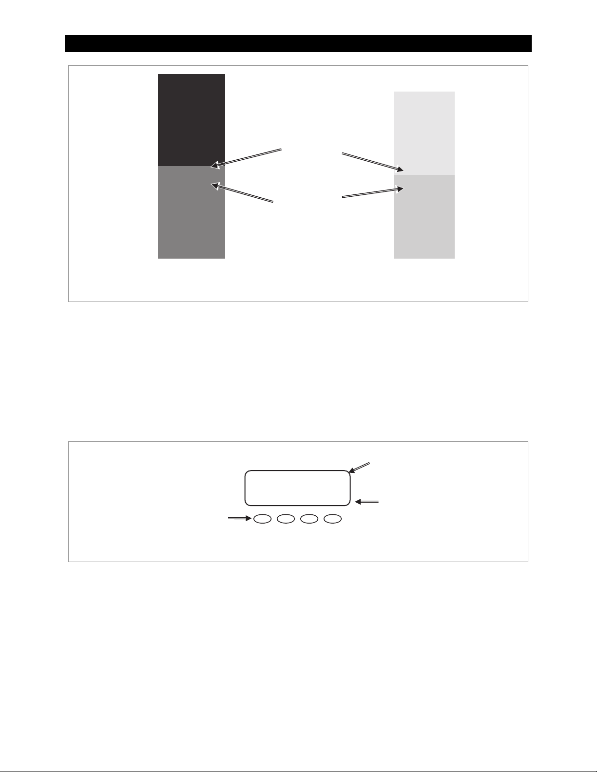
LCD Screen
Soft Keys
FLEXmax 80
Figure 1 Charge Controller Features
Soft Keys
Four “soft” keys are located directly below the LCD. The functions of the soft keys will vary depending
on the location of the user within the menu structure. Some soft keys will be used for navigation.
Some soft keys will be used for programming.
Soft key functions are identified by text in the LCD screen directly above the key (e.g., EXIT). In this
manual, soft keys will be identified by brackets (for example, <EXIT>). Not every soft key may be used
in some screens.
LCD
Soft Key Commands
<EXIT>, <GO> etc.
Soft Key Buttons
Main Menu
Charger Aux Light
EQ Misc Advanced
Logging Stats
XIT GO
SK1 SK2
SK3 SK4
Figure 2 Soft Keys
6 900-0009-01-00 Rev C
Page 9
Installation
Standards and Requirements
All installations must comply with national and local electrical codes; professional installation is
recommended.
IMPORTANT:
The charge controller is designed for indoor installation or installation inside a
weatherproof enclosure. It must not be exposed to rain and should be installed out of
direct sunlight.
Grounding
This product is intended to be installed as part of a permanently grounded electrical system as shown
in the wiring diagrams shown in Figure 6, Figure 7, and Figure 8.
The FLEXmax equipment ground is marked with this symbol:
The following important restrictions apply unless superseded by local or national codes:
The negative battery conductor should be bonded to the grounding system at only one point in the system.
If a GFDI is present, the battery negative and ground are not bonded together directly but are connected
together by the GFDI device when it is on. All negative conductor connections must be kept separate from
the grounding conductor connections.
The FLEXmax controller is not intended to be wired into a positive-ground configuration. However, certain
telecom applications may require this configuration. If it is necessary to build a positive-ground system with
OutBack products, contact OutBack Technical Support at
Additionally, consult the online forum at
discussed extensively.
If damaged or malfunctioning, the FLEXmax should only be disassembled and repaired by a qualified service
center. Please contact the local renewable energy dealer/installer for assistance. Incorrect reassembly risks
malfunction, electric shock or fire.
www.outbackpower.com/forum/
+1.360.618.4363
before proceeding.
, where this subject has been
DC and Battery-Related Installation Requirements
Shut off all DC circuit breakers before connecting any wiring.
Torque all the FLEXmax wire lugs and ground terminals to 4 Nm (35 in-lb).
Copper wiring must be rated at 75°C or higher.
Use up to 35 mm
can reduce performance and possibly damage the unit).
Run positive and negative cables side by side.
~ Keep cables together (e.g., using a tie-wrap) as much as possible to allow the inductive currents
to cancel.
~ Ensure paired cables pass through the same knockout and conduit fittings.
DC battery overcurrent protection must be used as part of the installation. OutBack offers both circuit
breakers and fuses for overcurrent protection.
900-0009-01-00 Rev C 7
2
(2 AWG) to reduce losses and ensure highest performance of the FLEXmax (smaller cables
Page 10
Installation
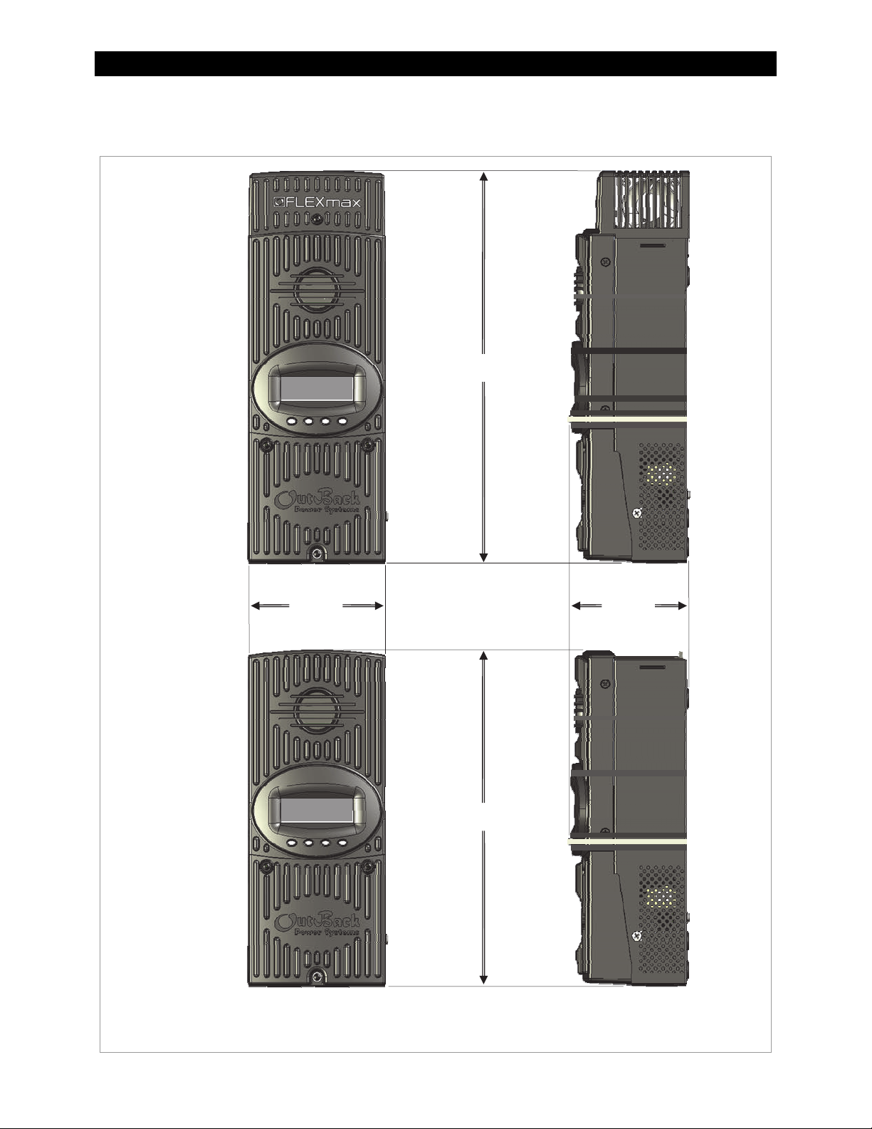
Dimensions
FLEXmax 80
Charge Controller
5.75”
(14.6 cm)
16.25” (41.3 cm)
4.0”
(10.2 cm)
FLEXmax 60
Charge Controller
13.5” (34.3 cm)
Figure 3 FLEXmax 80 and FLEXmax 60 Dimensions
8 900-0009-01-00 Rev C
Page 11
Mounting the Charge Controller
pp
IMPORTANT:
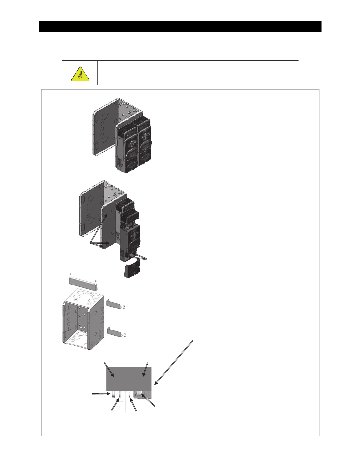
Install the FLEXmax in an upright position out of direct sunlight.
The FLEXmax is designed to attach
directly to OutBack’s FLEXware 500 DC
and FLEXware 1000 DC enclosures
(FLEXware 500 shown) or attach to its
own charge controller brackets (FW-CCB,
FW-CCB2, and FW-CCB2T).
Mounting directly to a FLEXware DC
enclosure:
1. Remove the fan cover and bottom
cover from the FLEXmax.
2. Insert a #10 X 3/8” sheet metal screw
in the top hole on the side of the DC
enclosure. This will act as a hanging
screw for the keyhole slot at the top
center of the FLEXmax.
Installation
Holes for
#10 x 3/8” sheet
metal screws
DC Enclosure
Bushing
3. Hang the FLEXmax on the top screw
Insert screws
through lower
holes inside
the charge
controller.
and line up its bottom two screw
holes with the holes on the enclosure.
4. Insert a #10 x 3/8” sheet metal screw
through each hole and tighten
against the enclosure (screws are
included with each DC enclosure).
5. Keep the cover off until wiring is
completed.
The conduit nipple assembly creates a
sealed connection from the FLEXmax to
the enclosure.
Charge Controller
(front view)
Mounting to Plywood
Use 1-5/8” wood screws to secure the
FLEXmax at the top slotted holes and
other interior lower holes as needed,
making sure the unit is straight and level.
Conduit
Lock Nut
Lock Nut
Ni
le
Figure 4 Mounting the Charge Controller
900-0009-01-00 Rev C 9
Page 12
Installation
Wiring
This section provides instructions on installing PV array wiring into the FLEXmax controller. See
page 98 for more notes on PV array sizing and operation.
Wire and Disconnect Sizing
IMPORTANT:
Wire sizes must comply with local and national codes. Input conductors and circuit
breakers must be rated at 1.56 times the short-circuit current of the PV array (per
NEC). OutBack 100% duty continuous circuit breakers only need to be rated at 1.25
times the short-circuit current.
Copper wiring must be rated at 75°C or higher.
Use up to 2 AWG (33.6 mm
FLEXmax (smaller cables can reduce performance and possibly damage the unit).
FLEXmax 80
The output current limit of the FLEXmax 80 is 80 amps.
2
) to reduce losses and ensure high performance of the
Install OutBack PNL-80-DC circuit breakers for disconnect and overcurrent protection
Use a minimum of #4 AWG (25 mm
conductors.
The largest PV array must have a rated short-circuit current of 64 amps or less under STC (Standard
Test Conditions).
Torque all the FLEXmax wire lugs and ground terminals to 4 Nm (35 in-lb).
2
) wire for the output between the FLEXmax 80 and the battery bus bar
FLEXmax 60
The output current limit of the FLEXmax 60 is 60 amps.
Install OutBack PNL-60-AC/DC or PNL-80-DC circuit breakers for disconnect and overcurrent protection.
Use a minimum of #6 AWG (16 mm
conductors.
The largest PV array must have a rated short-circuit current of 48 amps or less under STC (Standard
Test Conditions).
Torque all the FLEXmax wire lugs and ground terminals to 4 Nm (35 in-lb).
Please refer to the NEC and other electrical codes for recommendations on PV array cable sizing and
recommended length and ampacity.
2
) wire for the output between the FLEXmax 60 and the battery bus bar
10 900-0009-01-00 Rev C
Page 13
Installation
Wiring Compartment
WARNING: Shock Hazard
Make sure all DC circuit breakers are OFF (open) BEFORE making any wiring
connections. Use a DVM to check for voltage on all wires.
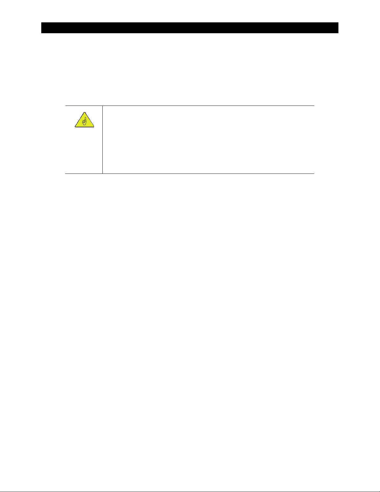
The PV (-) and BAT (-) terminals are connected internally. Only one negative wire may be needed to
connect to the (-) wire lugs if the PV - and BAT- conductors are bonded at the negative bus bar.
See Figure 6, Figure 7, and Figure 8 for sample wiring diagrams.
Auxiliary output
terminals
Battery Remote
Temp Sensor (RTS)
RJ11 port
MATE/HUB
RJ45 port
Wire terminals
PV+ PV– BAT– BA T+
Use up to 35 mm
(2 AWG) wire
Torque to 4 Nm
(35 in-lb)
Chassis/Equipment
Ground Lug
Screw holes for mounting the
charge controller
Figure 5 Wiring Compartment
CAUTION: Equipment Damage
Each FLEXmax requires its own PV array. DO NOT PARALLEL FLEXmax PV+ and PVTERMINALS ON THE SAME ARRAY!
2
An optional battery Remote Temperature Sensor (RTS) is recommended for accurate battery charging.
Only one RTS is needed for multiple OutBack inverter/chargers and charge controller units when the system
includes an OutBack HUB and a system display.
When one RTS is used, it must be connected to the component plugged into the Port 1 of the HUB.
900-0009-01-00 Rev C 11
Page 14
Installation
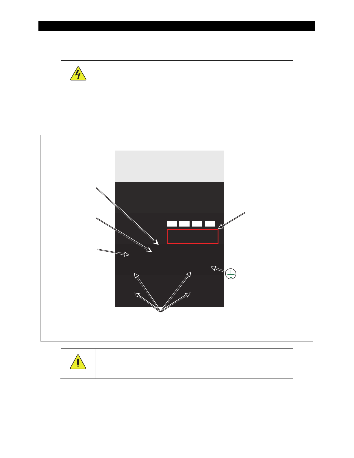
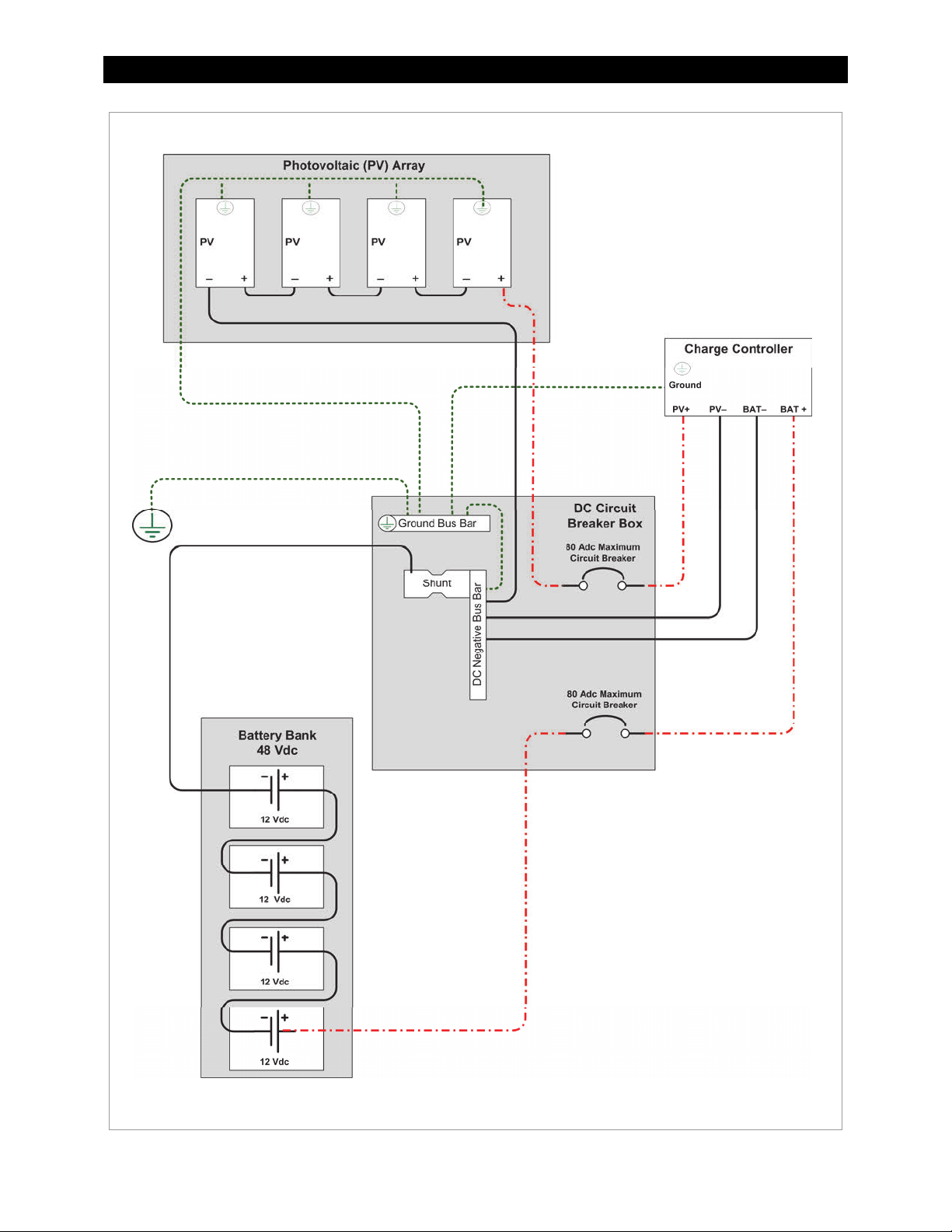
Figure 6 Wiring Diagram - Single Charge Controller with PV Array
12 900-0009-01-00 Rev C
Page 15
Installation
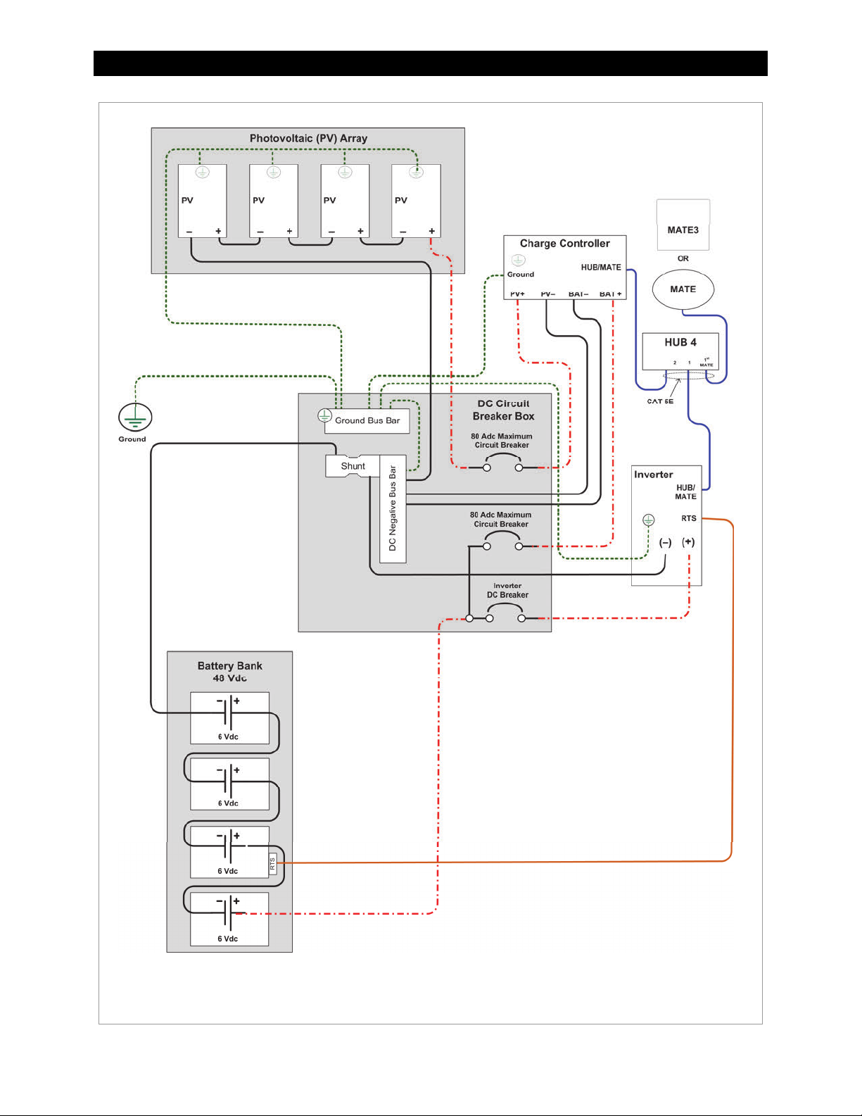
Figure 7 Wiring Diagram – Charge Controller with PV Array and Inverter
900-0009-01-00 Rev C 13
Page 16
Installation
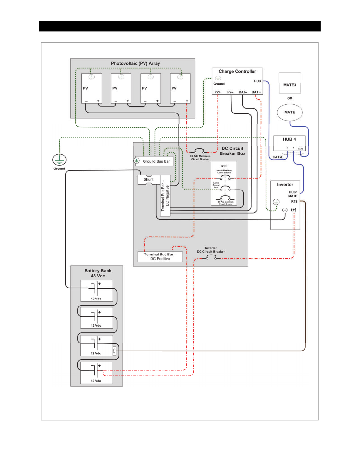
Figure 8 Wiring Diagram – Charge Controller with
PV Array Ground Fault Protection
14 900-0009-01-00 Rev C
Page 17
Operation
T
Operation of this unit consists of monitoring screens and programming screens. The majority of
programming screens are accessed using the main menu. See page 24.
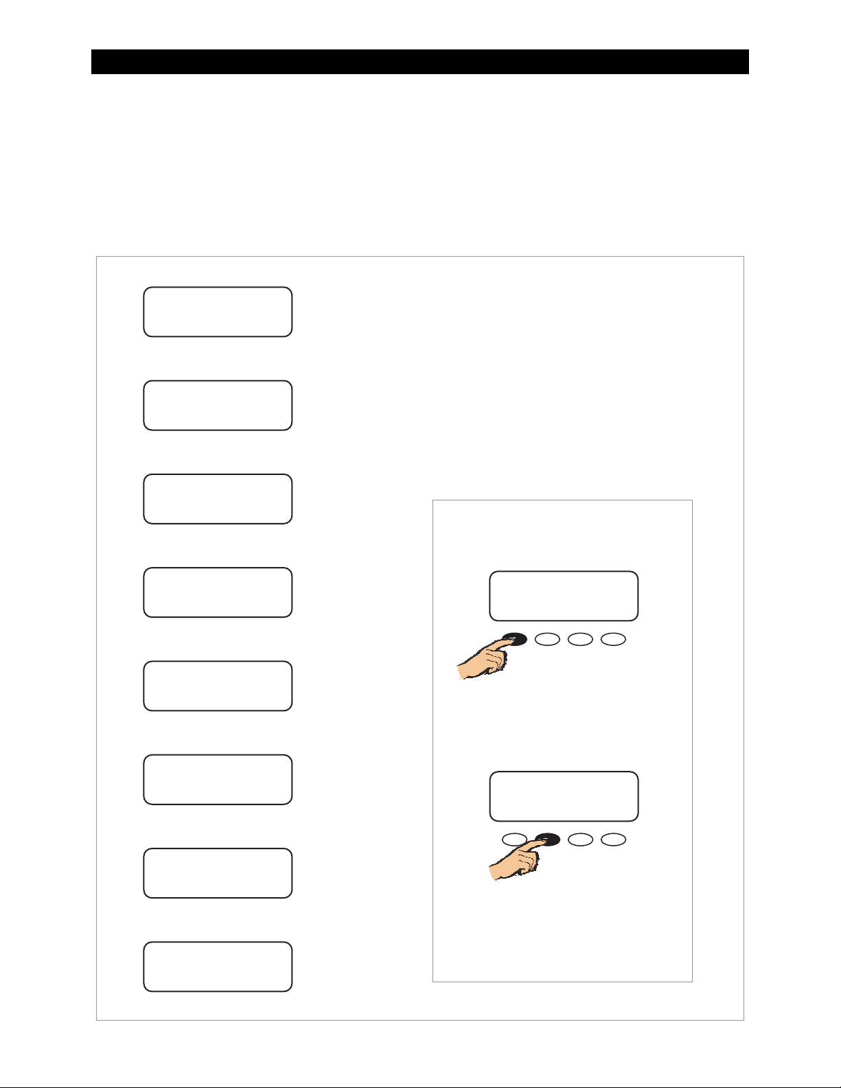
Power Up Screens
IMPORTANT:
The default settings of the FLEXmax are for a 12 Vdc battery bank. Change the
setting after powering up if a different battery voltage is used.
Once set, the FLEXmax retains the nominal voltage setting. Following any type of
shutdown or disconnect, it will return to operation automatically.
The PV array voltage is automatically detected. The PV array voltage must never
exceed 150 Voc.
It is recommended to restore the FLEXmax to factory default settings (see page 53)
and reset the nominal voltage any time the system is substantially revised or the
controller is relocated.
The FLEXmax uses power from the battery bank to operate. The battery voltage must be at least
10.5 volts or higher to power up the FLEXmax. When battery power is detected, the FLEXmax will go
through a series of power-up screens.
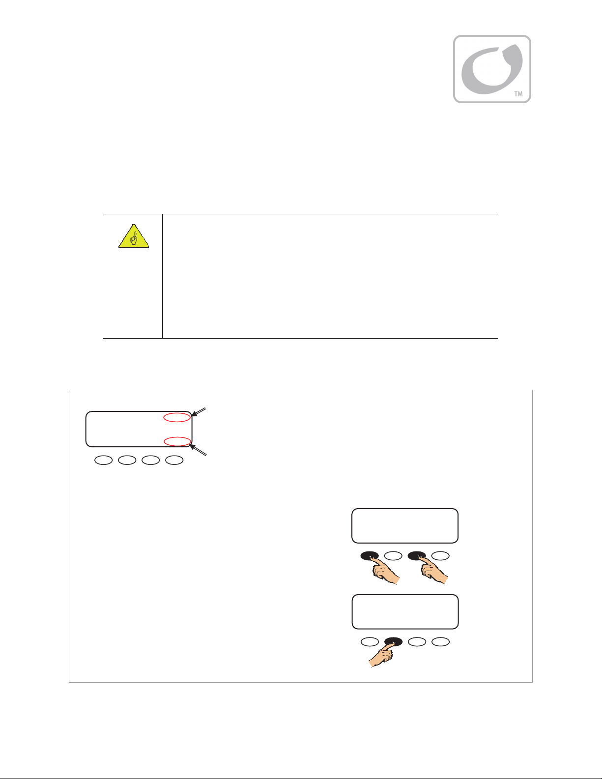
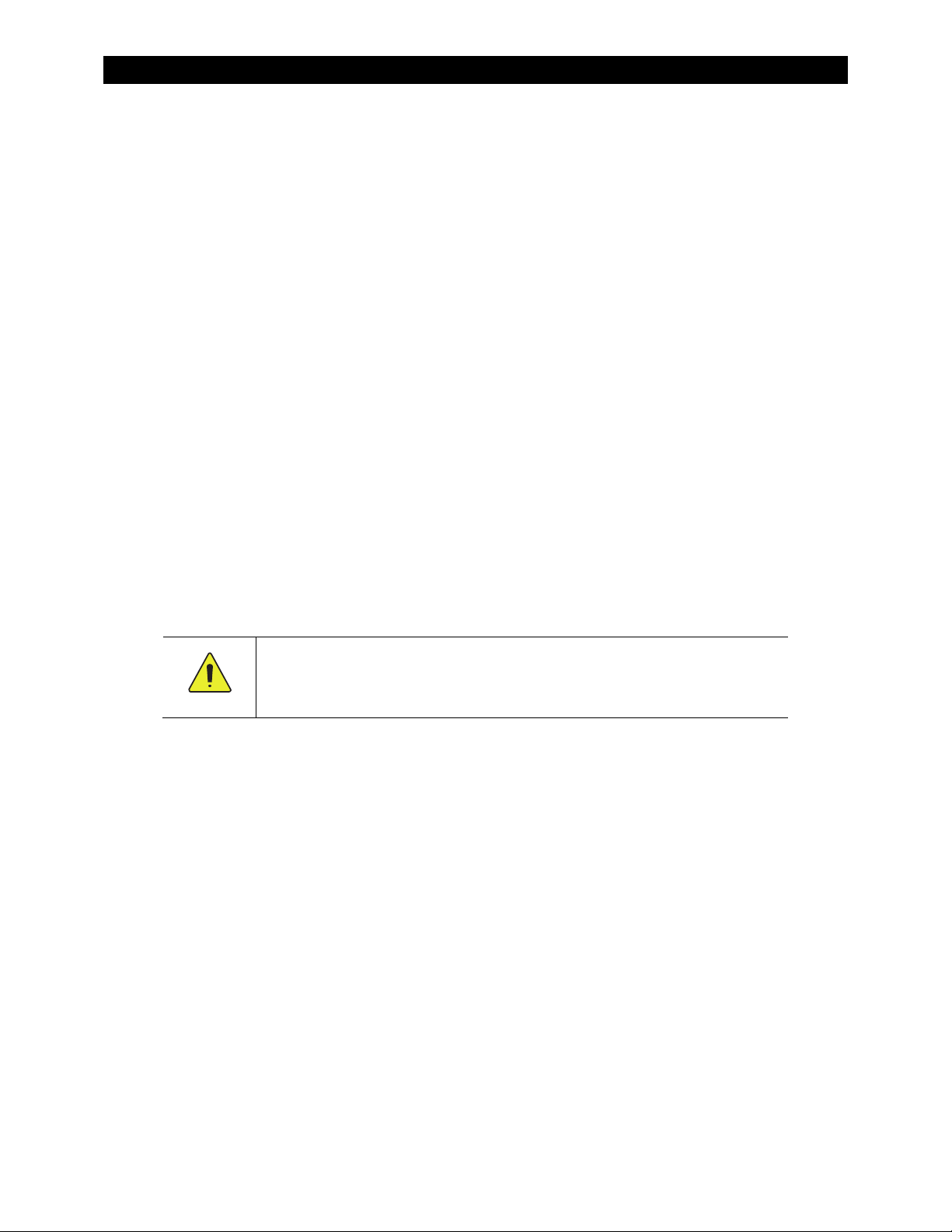
Power Up Screen
OutBack 12V
Power
Systems
Charge Controller - AU
To change version settings:
While turning on the circuit breaker, press and hold the first
and third soft keys. This brings up the Select Version screen.
Changing the version settings requires entering a password.
NOTE: This process will reset the FLEXmax to its default
settings. It may be necessary to re-enter previous settings.
To change the system password:
1. Press <NEXT> or <SEL> when the Select Version screen
appears on power up.
This will open the PASSWORD screen.
2. Press <–> or <+> to reduce the number from 150 to 141.
3. Press <ENTRA> or <ENTER> to enter the new password.
System Voltage
On Australian
versions only
To power up the charge controller:
1. Ensure the PV array and battery circuit breakers are OFF.
2. Turn ON the battery circuit breaker only.
upper right corner of the screen. If the screen reads
Low Battery Voltage, please see the Troubleshooting
section on page 91.
If the Australian version was previously selected, AU will
be displayed in the lower right corner of the screen.
Figure 9 Powering up the FLEXmax
he FLEXmax will show the system battery voltage in the
OutBack 12V
Power
Systems
Charge Controller - AU
PASSWORD
CONTRASENA
***150***
ENTRA - + ENTER
Continued on next page...
PASSWORD
Screen
Select Version offers two types of options. The English (default) or Spanish selections offer
standardized charge settings in two languages. Selecting Australian leaves the menus in English, but
changes the charging parameters. (For details, see Table 6 on page 99.)
900-0009-01-00 Rev C 15
Page 18
Operation
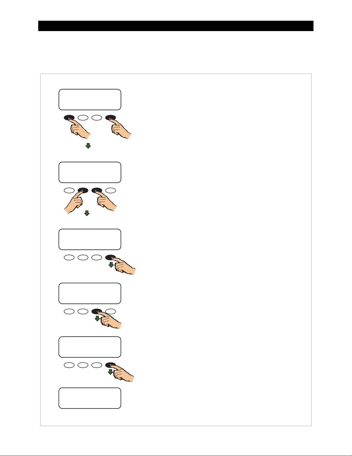
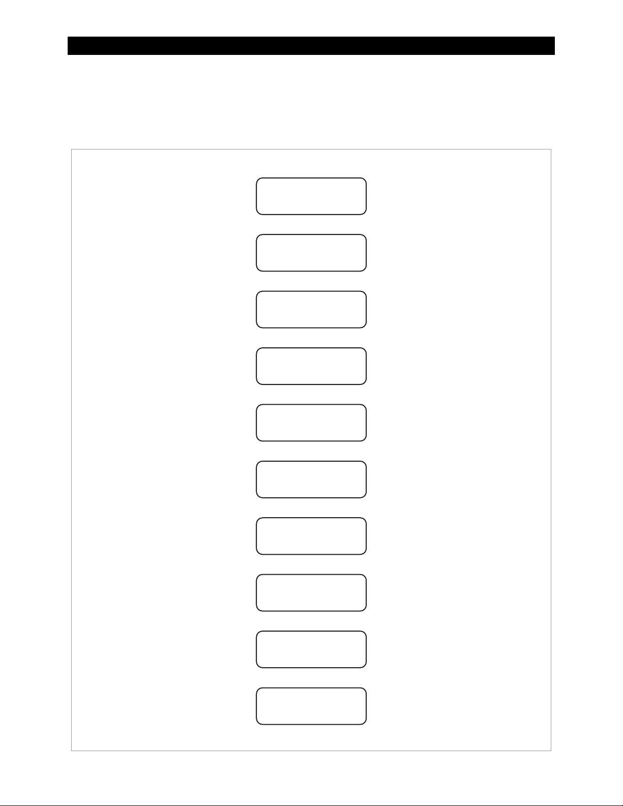
Version and/or Voltage Setting Screens
Once the password has been entered, the display will return to the Select Version screen.
Select Version Screen
Select Version
Elija la Version
English
NEXT ENTER ENTRA SEL
or
Select Version Screen
Select Version
Elija la Version
English
NEXT ENTER ENTRA SEL
or
Confirmation Screen
Are you sure?
English
NO YES
SYSTEM VOLTAGE Screen
SYSTEM VOLTAGE
12 24 36 48 60
^^
ENTER
To change the version:
1. Press <NEXT> or <SEL> to cycle through the version
choices of:
English,
Australian, or
Espanola.
2. When the desired version is displayed, press <ENTER> or
<ENTRA> to proceed to the confirmation screen.
3. Press <YES> to confirm the selection.
The SYSTEM VOLTAGE screen appears next.
The FLEXmax automatically detects the system’s battery voltage
and indicates it by placing two ^^ symbols below the value.
Verification Screen
Are you sure?
12 24 36 48 60
^^
NO YES
If the value indicated is correct, press <ENTER>.
If the value indicate is not correct for the present system,
press <> to move the ^^ to below the correct voltage.
Press <YES> to confirm the selection.
Status Screen
In 11.6V 0.0 A
Out 13.8V 0.0 A
0.000 kW 0.0 kWH
AUX: OFF Sleeping
The Status screen is the last screen to be displayed after startup.
The soft keys below the Status screen navigate to the main
menu and the End-of-Day summary screen. See page 17 for
details on the Status screen.
Figure 10 Changing the Version Setting
16 900-0009-01-00 Rev C
Page 19
Operation
Status Screen
The status screen displays system information. See page 18 for detailed information of the different
modes of operation.
The optional OutBack system display shows CC (Charge Controller) status screens for convenient
distant viewing from the installation location. See page 59 for the FLEXmax screens displayed on the
MATE3. Please see pages 71 to 83 to view the FLEXmax screens displayed on the MATE (or MATE2).
Status Screen
In 11.6V 0.0 A
Out 13.8V 0.0 A
0.000 kW 0.0 kWH
AUX: OFF Sleeping
In 11.6V 0.0 A
Out 13.8V 0.0 A
0.000 kW 0.0 kWH
AUX: OFF Sleeping
PV Input Voltage
PV Input Current
The PV voltage will slowly rise to the battery
voltage level even when the PV breaker is off –
this is normal as the PV capacitors charge up.
In 11.6V 0.0 A
Out 13.8V 0.0 A
0.000 kW 0.0 kWH
AUX: OFF Sleeping
In 11.6V 0.0 A
Out 13.8V 0.0 A
0.000 kW 0.0 kWH
AUX: OFF Sleeping
In 11.6V 0.0 A
Out 13.8V 0.0 A
0.000 kW 0.0 kWH
AUX: OFF Sleeping
In 11.6V 0.0 A
Out 13.8V 0.0 A
0.000 kW 0.0 kWH
AUX: OFF Sleeping
In 11.6V 0.0 A
Out 13.8V 0.0 A
0.000 kW 0.0 kWH
AUX: OFF Sleeping
Battery Voltage
Output Current
Instantaneous
Kilowatts
Daily Accumulated
Kilowatt-hours
AUX Status
(ON or OFF)
Navigation
Status Screen
In 11.6V 0.0 A
Out 13.8V 0.0 A
0.000 kW 0.0 kWH
AUX: OFF Sleeping
Pressing the first soft key (SK1)
opens the main menu screen.
Status Screen
In 11.6V 0.0 A
Out 13.8V 0.0 A
0.000 kW 0.0 kWH
AUX: OFF Sleeping
Pressing SK2 opens the end-of-day
summary menu and logging.
In 11.6V 0.0 A
Out 13.8V 0.0 A
0.000 kW 0.0 kWH
AUX: OFF Sleeping
Mode of Operation
See page 20
Figure 11 Status Screen
900-0009-01-00 Rev C 17
Page 20
Operation
End-of-Day Summary Screen
The end-of-day summary screen appears after one hour of continuous Sleeping (see page 23). This
screen can be opened any time by pressing the second soft key while in the status screen, providing a
summary up to that point.
End-of-Day Screen
Today 000Ah 00.0kWH
011Vp 00.0Ap 0.00kWp
MAX 14.7 V ABS 01:00
MIN 14.6 V FLT 00:00
Day (up to 128 days)
Today 000Ah 00.0kWH
011Vp 00.0Ap 0.00kWp
MAX 14.7 V ABS 01:00
MIN 14.6 V FLT 00:00
Today 000Ah 00.0kWH
011Vp 00.0Ap 0.00kWp
MAX 14.7 V ABS 01:00
MIN 14.6 V FLT 00:00
Today 000Ah 00.0kWH
011Vp 00.0Ap 0.00kWp
MAX 14.7 V ABS 01:00
MIN 14.6 V FLT 00:00
Today 000Ah 00.0kWH
011Vp 00.0Ap 0.00kWp
MAX 14.7 V ABS 01:00
MIN 14.6 V FLT 00:00
Today 000Ah 00.0kWH
011Vp 00.0Ap 0.00kWp
MAX 14.7 V ABS 01:00
MIN 14.6 V FLT 00:00
Today 000Ah 00.0kWH
011Vp 00.0Ap 0.00kWp
MAX 14.7 V ABS 01:00
MIN 14.6 V FLT 00:00
Accumulated
Amp-hours
Accumulated kWh
Total Power
Peak Input Voltage
Peak Output Current
Peak Output Power
in Kilowatts
Maximum Battery
Voltage Obtained
NOTE:
When finished viewing the
end-of-day screen(s), be sure to
Today 000Ah 00.0kWH
011Vp 00.0Ap 0.00kWp
MAX 14.7 V ABS 01:00
MIN 14.6 V FLT 00:00
Today 000Ah 00.0kWH
011Vp 00.0Ap 0.00kWp
MAX 14.7 V ABS 01:00
MIN 14.6 V FLT 00:00
Accumulated
Absorb Time
Minimum Battery
Voltage Obtained
return the display to the status
screen. Otherwise, it will not reset
the counters when the sun rises the
next morning. The values will
continue to accumulate.
Today 000Ah 00.0kWH
011Vp 00.0Ap 0.00kWp
MAX 14.7 V ABS 01:00
MIN 14.6 V FLT 00:00
Accumulated
Float Time
Figure 12 End-of-Day Summary Screen
18 900-0009-01-00 Rev C
Page 21
Operation
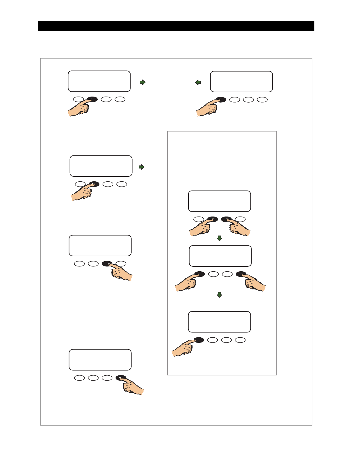
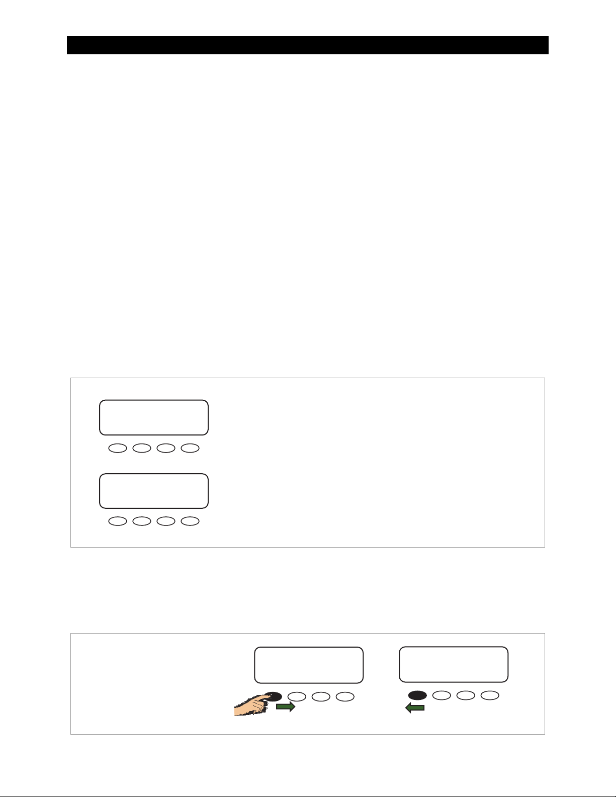
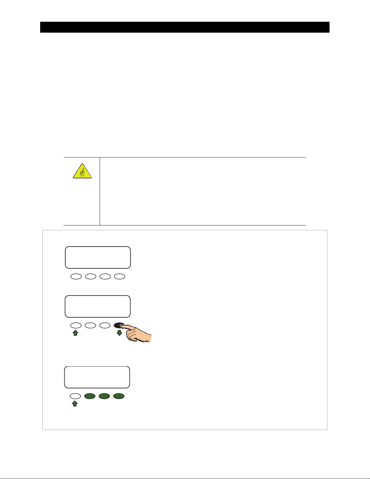
Navigating the End-of-Day Screens and Data Logging
Status Screen End-of-Day Screen
In 11.6V 0.0 A
Out 13.8V 0.0 A
0.000 kW 0.0 kWH
AUX: OFF Sleeping
Today 000Ah 00.0kWH
011Vp 00.0Ap 0.00kWp
MAX 14.7 V ABS 01:00
MIN 14.6 V FLT 00:00
Pressing the second soft key
(SK2) opens the end-of-day
summary menu/logging.
End-of-Day Screen
Today 000Ah 00.0kWH
011Vp 00.0Ap 0.00kWp
MAX 14.7 V ABS 01:00
MIN 14.6 V FLT 00:00
Press SK2 to open the
CLEAR LOG screen.
End-of-Day Screen
Today 000Ah 00.0kWH
011Vp 00.0Ap 0.00kWp
MAX 14.7 V ABS 01:00
MIN 14.6 V FLT 00:00
Press SK1 to return to the
status screen.
CLEAR LOG Screen
The daily statistics or the accumulated
statistics are stored on the charge controller's
static memory. A new log “day” begins when
the controller enters Wakeup. (See page 24.)
Logs accumulate for up to 128 days. See
pages 75 and page 76 for details.
CLEAR LOG
BACK TOTL DAILY
OR
Are you sure?
NO YES
OR
Press SK3 to open the previous
day’s summary screen.
Continuing to press this soft key
will cycle back through the last
128 daily summary screens.
End-of-Day Screen
Today 000Ah 00.0kWH
011Vp 00.0Ap 0.00kWp
MAX 14.7 V ABS 01:00
MIN 14.6 V FLT 00:00
End-of-Day Screen
Today 000Ah 00.0kWH
011Vp 00.0Ap 0.00kWp
MAX 14.7 V ABS 01:00
MIN 14.6 V FLT 00:00
Press SK1 to return to the
status screen.
This data log can be downloaded to an SD
Pressing SK4 will bring up
the summary for the 128
day back.
th
card. The MATE3 system display is required
for this download. See page 69 for details on
this feature.
Figure 13 Navigating the End-of-Day Summary Screen
900-0009-01-00 Rev C 19
Page 22
Operation
Modes of Operation
The FLEXmax has 25 different modes that will display on the status screen. These messages will vary
with function. The FLEXmax modes consist of various charging stages, equalization, various reasons
for stopping charging, and certain specialized operating modes.
The amount of time required before starting operation is dependent on the module type, ambient
temperature, and the amount of sunlight directly on the PV array. Normally, the FLEXmax starts in the
morning within a few minutes of the PV array being exposed to direct sunlight.
The FLEXmax modes of operation will change occasionally during the day based on the PV array
output and the battery system state of charge. The FLEXmax operating modes are displayed at the
bottom right hand corner of the status screen. See Figure 11.
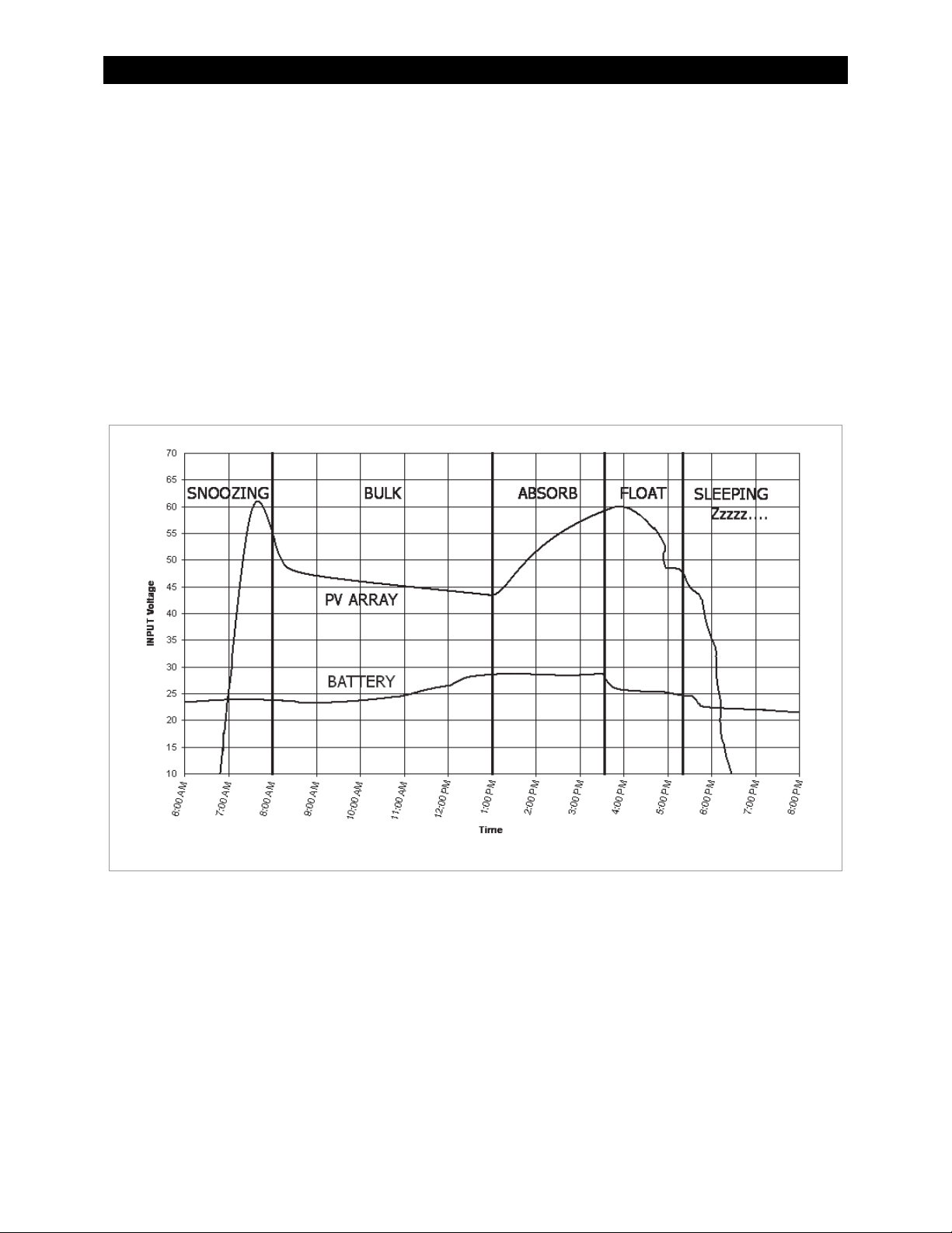
Figure 14 shows an example of the various stages of operation during battery charging and the
messages shown during each stage. Battery charging is described in detail on page 96.
Figure 14 FLEXmax Battery Charging and Modes
Absorbing
The FLEXmax is in the Absorbing stage of a three-stage cycle, regulating the battery voltage at the
Absorbing voltage set point. While the batteries are held at this voltage, the ChgT counter in the Misc
menu counts up from zero toward the user-defined Absorb Time Limit. (See pages 44 and 49.) The
charger will exit this stage and enter the Float stage if the ChgT timer reaches the time limit, or if the
Absorb End Amps setting is reached. (See page 49.)
If the battery voltage drops below the Absorbing voltage (see page 26), the FLEXmax reverts back to
the Bulk charge stage and displays MPPT Bulk as shown on page 22. The ChgT counter will begin
counting back toward zero. Lower voltages will cause the timer to subtract minutes at a faster rate, as
shown on Table 1 on page 21.
20 900-0009-01-00 Rev C
Page 23

Operation
Table 1 Battery Voltage and Charge Timer
Battery Voltage ChgT (Charge Timer) Activity/Display
12.4 V, 24.8 V, 37.2 V, 49.6 V, or 62.0 V,
and less than the Absorbing voltage
<12.4 V, 24.8 V, 37.2 V, 49.6 V, or 62.0 V For every minute elapsed, 1 minute is
<12.0 V, 24.0 V, 36.0 V, 48.0 V, or 60.0 V For every minute elapsed, 2 minutes is
< 11.6 V, 23.2 V, 34.8 V, 46.6 V, or 58.0 V For every minute elapsed, 4 minutes is
No change.
subtracted from the timer
subtracted from the timer
subtracted from the timer.
Auto Start (Auto ReStart)
This setting allows the user to choose between continuous MPP tracking or occasional restarts of the
sweeping process. A restart means the controller abandons the existing maximum power point and
“re-sweeps”, or begins gathering new power point data. See page 52 for more information.
Mode 1: Once every 1.5 hours in the Bulk charging stage
Mode 2: Once every 1.5 hours in the Bulk, Absorbing and Float recharging stages
Mode 0: Auto ReStart is disabled completely. It will continously track the maximum power point without
starting over.
NOTE: If enabled, AutoStart also occurs during the MPPT EQ cycle. See page 23.
BatTmpErr
The battery temperature sensor is shorted or damaged. The charging voltage will not be temperature
compensated and the cooling fan will continuously operate. See the section on RTS compensation on
page 50.
BatTooHot
The battery temperature sensor has detected a battery temperature of over 50°C. The FLEXmax will
stop charging the battery and wait for the battery to cool below 50°C.
Charged
There is an external DC source other than PV keeping the battery above the Float voltage set point
(see page 26). The FLEXmax will stop charging because it is not needed. The display may also appear
when the cycle is transitioning from Absorbing (upper target voltage) to Floating (lower voltage).
EQ
The charger is in a cycle of equalization. (See page 42.) This is the time elapsed in hours and minutes
since the BATTERY EQUALIZE VOLTS set point was met.
If this set point is not maintained, the controller will revert back to MPPT EQ. (See page 23.) The EQ
timer will pause until the batteries are regulated at the BATTERY EQUALIZE VOLTS set point again.
The paused time can be viewed in the End-of-day Summary screen (see page 18).
EQ Done
Once the set EQ time (between 1 and 7 hours) has successfully completed, the FLEXmax will transition
to Float stage. EQ Done will be displayed either until a button is pressed or the next morning’s
wakeup. The FLEXmax will transition to Float stage at the end of the completed equalization cycle.
900-0009-01-00 Rev C 21
Page 24
Operation
EX-Absorb
There is an external DC source other than PV keeping the battery above the Absorbing voltage set
point. The FLEXmax will stop charging because it is not needed.
Floating
The FLEXmax is in the Float stage of a three-stage cycle, regulating the battery voltage at the Float
voltage set point. This stage is temperature compensated. (See page 97.) If the battery voltage drops
below the Float voltage, the FLEXmax will employ the MPPT function to draw more power from the
PV array. (This may occur if the batteries are powering loads.) If this happens, the operating mode will
change to MPPT Float. (See below.)
GT Mode
The FLEXmax is in Grid-Tie mode. In a system with an OutBack grid-interactive inverter, a HUB, and a
system display, the FLEXmax will display GT Mode, if and only if, the inverter is in Sell mode and the
FLEXmax is in the MPPT BULK or MPPT FLOAT modes. This message also indicates that Grid-Tie mode
communication has been established between the inverter and charge controller. GT must be
selected in the MPPT Mode advanced menu in order to be viewed. (See page 47.)
High Voc
This indicates the PV array’s open-circuit voltage is too high for the controller to safely operate
(> 145 Vdc). This should only occur with systems using 72 Vdc nominal PV arrays in very cold
temperatures (below -15°C / 5°F). The FLEXmax will automatically restart operation once the PV
array’s open-circuit voltage falls to a safe level (145 Vdc or lower).
CAUTION: Equipment Damage
Voltages in excess of 150 Vdc are likely to damage the FLEXmax controller. The PV array
should be designed to avoid ever reaching these voltages.
Low Light or Snoozing
A Low Light or Snoozing mode indicates that the PV voltage is high enough to activate the FLEXmax,
but there is not enough current available to charge. During the initial tracking (see Wakeup and
Tracking), if it is determined to be too late (or too early) in the day, the FLEXmax will display Low Light
for a few seconds and then display Snoozing for five minutes (default). This reduces energy usage and
unnecessary powering of the FLEXmax. This message is also displayed in extremely cloudy weather.
MPPT Bulk
This is a Maximum Power Point Tracking mode which harvests the maximum wattage available from
the PV array. The controller is trying to regulate the battery voltage towards the Absorbing voltage
set point. Normally the charge controller enters this mode at the beginning of the day or when a new
charge cycle begins. The controller may also enter this stage if there is not enough PV energy to
maintain a different stage, such as Absorbing. See page 20 for more information.
MPPT Float
This is a Maximum Power Point Tracking mode which harvests the maximum wattage available from
the PV array. The controller is trying to regulate the battery voltage towards the Float voltage set
point. Normally, the charge controller enters this mode if it was in the Floating mode (see above) and
there was not enough energy to maintain the battery voltage.
22 900-0009-01-00 Rev C
Page 25

Operation
MPPT EQ
The equalization cycle has started and the charge controller is trying to regulate the batteries at the
BATTERY EQUALIZE VOLTS set point. Once this voltage has been reached, the displayed mode will
change to EQ.
Before equalizing, battery loads should be turned off and the battery should be charged so the charge
controller can quickly reach the EQ voltage set point. Otherwise, the charge controller may have
difficulty reaching or maintaining the equalization process.
Equalization is not battery temperature compensated.
New Voc
The FLEXmax is measuring a new open-circuit panel voltage (Voc). This mode tells the user that
external conditions have changed. After displaying this message, the charge controller will enter
Tracking mode to perform power point tracking again.
OvrCurrent
This condition occurs if more than 6 amps flows from the battery to the FLEXmax, or if more than
100 amps is drawn from the FLEXmax by the battery. To reinitiate power production, press <RSTRT>
in the Misc menu (see page 45). If this continues to occur, the unit may be malfunctioning.
Over Temp
The FLEXmax is too hot. If this message appears, carefully check to see if the heat sink is extremely
hot. To help control its operating temperature, avoid installing the FLEXmax in direct sunlight.
Re-Cal
There are certain conditions that can confuse the current measuring method in the FLEXmax. If this
happens, the FLEXmax will temporarily stop and re-calibrate. This may happen because of high
temperatures or current flowing from the battery. After displaying this message, the charge controller
will enter Tracking mode to perform power point tracking again.
Sleeping
The PV voltage is two volts less than the battery voltage. This normally appears at night, when no PV
energy is available. This may also appear during the day when the FLEXmax is transitioning between
certain states, or due to other conditions. After three hours of Sleeping, the FLEXmax will transition to
Zzzzz... mode.
Sys Error
This indicates an internal non-volatile memory error. The unit will stop operating when this message
is displayed. Call OutBack Technical Support if this message appears (+1.360.618.4363).
Tracking
In Tracking mode, the FLEXmax is doing an initial tracking of the panel voltage from Voc towards
battery voltage after wakeup. This is also displayed when the controller transitions from a target set
point (Absorbing, Floating, or EQ) to the MPPT state (MPPT Bulk, MPPT Float, or MPPT EQ).
900-0009-01-00 Rev C 23
Page 26
Operation
E
T
Unloaded
The battery terminals have become disconnected. This may mean that the battery circuit breaker
breaker has tripped. It can also appear if the nominal battery voltage is set too low.
Wakeup
As the PV open circuit voltage (Voc) rises above the battery system voltage by two volts, the FLEXmax
prepares to deliver power to the batteries, although it does not perform MPPT in this mode. During
this period (initial tracking), the FLEXmax is calculating the PWM duty cycles, turning on power supply
voltages in the proper sequences, and making internal calibrations. It also measures a new Voc at this
time. In Wakeup, the daily statistics of a single FLEXmax (amp-hours, kilowatt-hours, etc.), will
accumulate into the total statistics. The daily statistics and the end-of-day summary will clear, and the
controller will begin logging a new “day”. A FLEXmax combined with a HUB and a MATE will log this
information at midnight. On the MATE3, the data logging will occur at the interval scheduled in the
MATE3 data logging parameters.
Zzzzz...
The FLEXmax will display Zzzzz... after 3 hours of continuous Sleeping. This transition indicates that
the controller recognizes it is night. It will perform Wakeup when voltage is available (see above).
Initial Operation
Status
Screen
In 113.6V 0.0 A
Out 12.5V 0.0 A
0.000 kW 0.0 kWH
AUX: OFF Sleeping
Status
Scr
een
In 000.0V 0.0 A
Out 12.5V 0.0 A
0.000 kW 0.0 kWH
AUX: OFF Sleeping
urn the PV input circuit breaker ON. The FLEXmax automatically detects the
PV input voltage.
The FLEXmax enters Wakeup, transitions to Tracking, and prepares to
charge the batteries by tracking the maximum power point of the solar array.
During the initial tracking, the input PV source is gradually loaded from the
open-circuit voltage (Voc) to ½ of the Voc. Within this range, the FLEXmax
seeks the maximum power point.
When the FLEXmax goes into Re-Cal, Auto Restart, or Wakeup, modes,
among other conditions, it performs an initial tracking.
If PV voltage registers 000V when the PV circuit breaker is
ON, check the polarity of the PV connections.
Figure 15 Initial Operation
Changing the Settings on the FLEXmax
Accessing the Main Menu
The main menu allows the user to adjust and calibrate the FLEXmax for maximum performance.
Status Screen
From the status screen, press SK1 to
open the main menu screen.
To return to the status screen from the
main menu, press <EXIT>
(also SK1).
In 113.6V 0.0 A
Out 12.5V 0.0 A
0.000 kW 0.0 kWH
AUX: OFF Sleeping
Figure 16 Accessing the Main Menu
Main Menu
Charger Aux Light
EQ Misc Advanced
Logging Stats
XIT GO
24 900-0009-01-00 Rev C
Page 27

Main Menu Map
Operation
Main Menu
Charger Aux Light
EQ Misc Advanced
Logging Stats
EXIT GO
<EXIT> returns to the Status screen.
<> moves the cursor to the left.
<> moves the cursor to the right.
<GO> goes to the setup screen for the
chosen option.
Charger Aux Light
EQ Misc Advanced
Logging Stats
EXIT GO
Charger Aux Light
EQ Misc Advanced
Logging Stats
EXIT GO
Charger Aux Light
EQ Misc Advanced
Logging Stats
EXIT GO
Charger Aux Light
EQ Misc Advanced
Logging Stats
EXIT GO
Charger Aux Light
EQ Misc Advanced
Logging Stats
EXIT GO
Charger Aux Light
EQ Misc Advanced
Logging Stats
EXIT GO
Charger Aux Light
EQ Misc Advanced
Logging Stats
EXIT GO
Charger Aux Light
EQ Misc Advanced
Logging Stats
EXIT GO
Figure 17 Main Menu
From the main menu, a user can choose among the
following FLEXmax functions by aligning the arrow
next to the desired selection.
Charger—CHARGER SETUP
Adjusts the Current Limit, Absorbing,
and Float recharging voltage set points.
See page 26 for details.
Aux
Provides a secondary control circuit for a vent fan,
See page 27 for details.
Light—BACKLIGHT CONTROL
Adjusts the backlighting of LCD screen and soft
See page 41 for details.
Activates battery equalization recharging
See page 42 for details.
Additional settings and service information.
See page 44 for details.
Optimizes/fine-tunes the charge controller.
See page 46 for details.
Logging—DATA LOGGING
Displays recorded power production information.
See page 54 for details.
Displays recorded peak system information and
See page 55 for details.
—AUX OUTPUT CONTROL
error alarm, and other system-related additions.
key buttons.
EQ
—BATTERY EQUALIZE
(manually or automatically).
Misc
—MISCELLANEOUS
Advanced
STATS
cumulative kilowatt-hours and amp-hours.
—ADVANCED MENU
—STATISTICS
900-0009-01-00 Rev C 25
Page 28
Operation
Charger Screen
Charging settings should follow the battery manufacturer's recommendations. This screen allows
changes to the recharging voltage set points if the default settings do not match the manufacturer's
recommendations. (For an explanation of battery charging, see pages 96 and 97).
Current Limit
Absorbing
Float
The default charger output current limit setting is:
80 amps for the FM80, and
60 amps for the FM60.
This setting is adjustable from 5-80 amps.
IMPORTANT:
Check the battery manufacturer’s recommendations for the optimal charging
settings for the type of batteries being used.
An appropriate circuit breaker, or overcurrent device, must be used between the
battery and the FLEXmax.
If a battery remote temperature sensor (RTS) is used, set the Absorbing and Float
setting voltage based on a 25°C/77°F setting. RTS compensated voltage values can
be viewed in the Advanced menu screen under the RTS Compensation heading.
Main Menu
Charger Aux Light
EQ Misc Advanced
Logging Stats
EXIT GO
Charger Aux Light
EQ Misc Advanced
Logging Stats
EXIT GO
To access the Charger screen and adjust the settings:
1. From the main menu, press the <> or <> soft key to
move the
2. Press <GO> to open the Charger screen.
The indicates which set point is selected.
3. Press <> to move the to the set point that needs to
be changed.
4. Press <+> to increase the value or (–) to decrease
the value.
to the left of the Charger function.
Charger Screen
Current Limit 80A
Absorbing 14.4V
Float 13.8V
EXIT
- +
To Exit:
Press <EXIT> once to return to the main menu.
Press <EXIT> twice to return to the status screen.
Figure 18 Charger Setup Menu
26 900-0009-01-00 Rev C
Page 29

Operation
Aux Screens
The AUX (Auxiliary) is a secondary control circuit — essentially, a small power supply that provides a
12 Vdc output current (up to 200 milliamps/2.4 watts) to an isolated load. It is either ON (Active High)
with 12 Vdc available at the output or OFF (Active Low) with 0 Vdc at the output. It can also be set to
AUTO, so that it activates when certain criteria are met.
The AUX output can respond to specific criteria and control cooling fans, vent fans, load diversion,
fault alarms, and automatic generator control. In some cases, such as the PV Trigger, Night Light, or
Diversion:Relay applications, the polarity of the output can be reversed so that a lack of power
activates the output. This function is controlled through the Aux Polarity screen in the ADVANCED
MENU. (See page 53.)
NOTE: Diversion:Relay and Diversion:Solid St can be used for AC coupling applications.
The AUX output can also be controlled externally through the system display. See the Owner's Manual
for the system display (if used) for details.
Only one
See Figure 27, page 39, for an auxiliary setup wiring diagram example.
AUX MODE
Mode Name Function/Purpose Set Points Aux Polarity
Vent Fan
Function:
When the threshold voltage set point is
exceeded, the AUX output will change state for
at least 15 seconds. If the set point continues to
be exceeded, the output will remain in that state
until the voltage falls below the set point.
Once the voltage decreases below the threshold
voltage, the AUX output will remain in that state
for another 15 seconds. It will then deactivate.
Purpose:
This mode is intended to operate a vent fan for a
battery enclosure to ventilate hydrogen gas
from the enclosure.
can operate at a time (even if other modes have been preset).
Table 2 Aux Mode Functions
Threshold
Voltage
Not Available
PV Trigger
900-0009-01-00 Rev C 27
Function:
When the threshold voltage set point is
exceeded, the AUX output will activate.
When the threshold voltage decreases below
the voltage set point, the output will remain
active for the duration of the hold time set by
the user.
Purpose:
This mode is intended to operate an alarm, or
relay that disconnects the PV array, when
PV input exceeds the threshold voltage set by
the user. The mode deactivates the alarm or
PV disconnect after the time set point has
reached.
been
NOTE: Do not exceed 150 Vdc or the FLEXmax
could be damaged.
Threshold
Voltage
Hold Time
Active High: Activates the
output when the voltage
exceeds the set point.
Active Low: Deactivates the
output when the voltage
exceeds the set point.
Page 30

Operation
Table 2 Aux Mode Functions
Mode Name Function/Purpose Set Points Aux Polarity
Error Output
Night Light
Float
Diversion:
Relay
Function:
When the voltage decreases below the
threshold voltage for 10 minutes or more, the
AUX output will change state.
Purpose:
This mode is useful for monitoring remote sites.
It is intended to signal when the charge
controller has not charged the batteries for 26
hours or more or if the battery voltage has fallen
below the threshold voltage for more than 10
minutes.
When set as Active Low, it can activate an alarm
by sending a signal through a modem to a
computer to alert the operator of the problem.
Function:
When the voltage drops below the threshold
voltage set point for the amount of time set in
the Hysteresis time, the AUX output changes
states and remains in that state for the amount
of time set for the ON time.
Purpose:
This mode is intended to illuminate a
user-provided, low wattage light for as long as
the charge controller remains in Sleep mode or
for the ON time set by the user.
Function:
When the FLEXmax is in the Float stage, the
output activates to power a load.
Purpose:
This mode is intended to power a load when the
FLEXmax is in the Float stage of charging the
batteries.
Function:
When the battery voltage exceeds the threshold
voltage, the AUX output changes state. Often
used with wind or hydroelectric sources.
Purpose:
This mode is intended to divert power from the
batteries to prevent overcharging by activating
a diversion load at the appropriate time.
Threshold
Voltage
Threshold
voltage
ON Time
Hysteresis
Time
None Not Available
Threshold
Voltage
Time
Not Available
Active High: Activates for a
set amount of time when the
voltage drops below the
threshold for a set amount
of time.
Active Low: Deactivates for a
set amount of time when the
voltage drops below the
threshold for a set amount of
time.
Active High: Controls an
auxiliary load to divert power
away from the batteries when
a wind or hydroelectric turbine
is connected directly to the
batteries.
Active Low: Deactivates an
auxiliary load to stop diverting
from batteries.
Diversion: Solid
St
Function:
When the battery voltage exceeds the threshold
voltage, the AUX output goes into pulse-width
modulation at a rate of 200 Hz. Often used with
wind or hydroelectric sources.
Purpose:
This mode is intended to divert power from the
batteries to prevent overcharging by operating
a diversion load at the appropriate PWM level.
Recommended for use with a solid-state relay
for fast and precise load control.
Threshold
Voltage
Time
Not Available
28 900-0009-01-00 Rev C
Page 31

Operation
q
A
A
A
Table 2 Aux Mode Functions
Mode Name Function/Purpose Set Points Aux Polarity
Low Battery
Disconnect
Function:
When the battery voltage falls below the
threshold disconnect voltage, the AUX output
activates. When the battery voltage rises above
the threshold reconnect voltage, the AUX
deactivates.
Purpose:
This mode is intended to operate a relay to turn
off loads and save battery capacity.
Threshold
Voltage for
disconnect
Threshold
voltage for
reconnect
Time delay
Not Available
Remote
Allows an OutBack system display to control the
AUX output (see the system display manual
for details).
AUX MODE Screen Navigation
Main Menu
Charger Aux Light
EQ Misc Advanced
Logging Stats
EXIT GO
Charger Aux Light
EQ Misc Advanced
Logging Stats
EXIT GO
AUX MODE Screen
AUX MODE
Night Light
Output: Off Off
EXIT NEXT SET MODE
NOTE: If more than 10 minutes have passed since
any activity, the PASSWORD screen becomes active,
re
uiring the user to reenter the password (141).
Figure 19 Aux Screen Navigation
To access the AUX MODE screen and adjust the settings:
1. From the main menu, press <> or <> to move the to
2. Press <GO> to open the Aux screen.
3. Press <NEXT> to cycle through the available auxiliary modes.
4. Press <MODE> to cycle through the mode set points ON, OFF,
5. Press <SET> to select the set point(s) (if available).
6. Press <EXIT> once to return to the main menu.
7. Press <EXIT> twice to return to the status screen.
UX MODE
None Not Available
the left of Aux.
or AUTO. In AUTO mode, the function will automatically
activate when a user-determined value is met and deactivate
(or shut down) when other conditions are met, such as a
certain amount of time passing.
ux Polarity
See page 53.
UX MODE
Set Point
Name
AUX MODE
Night Light
Output: Off Off
EXIT NEXT SET MODE
900-0009-01-00 Rev C 29
Page 32

Operation
Vent Fan (AUX Mode)
This mode is intended to operate a vent fan for a battery enclosure which helps ventilate hydrogen
gas from the enclosure. If the voltage remains above the threshold voltage set point, the vent fan will
remain active.
When the voltage falls back below the set point, the vent fan will continue for another 15 seconds,
then turn off.
Main Menu
Charger Aux Light
EQ Misc Advanced
Logging Stats
EXIT GO
Charger Aux Light
EQ Misc Advanced
Logging Stats
EXIT GO
To set the mode for Vent Fan:
1. From the main menu, press <> or <> to move the
to the left of Aux.
2. Press <GO> to open the AUX MODE screen.
3. The Vent Fan screen should be the first default screen to
display. If any other mode screen is displayed, press
<NEXT> to cycle through the available modes until
Vent Fan is displayed again.
4. Press <MODE> to switch between ON, OFF, or AUTO.
ON activates the AUX output.
OFF deactivates the AUX output.
AUTO controls the output according to the criteria of
the selected AUX mode.
AUX MODE
Vent Fan
Output: Off Off
EXIT NEXT SET MODE
<NEXT> advances to the
next AUX MODE screen.
AUX MODE
Vent Fan
Output: Off Off
EXIT NEXT SET MODE
AUX MODE
Vent Fan
EXIT VOLT
VENT FAN VOLTS
> 14.4
BACK - +
To change the set points for Vent Fan:
1. Press <SET> to advance to the set point screen.
2. Press <VOLT> to advance to the VENT FAN VOLTS screen.
3. Press <-> or <+> to increase or decrease the value.
4. Press <BACK> to return to the Vent Fan set point screen.
5. Press <EXIT> to return to the AUX Mode screen.
To Exit:
Press <EXIT> once to return to the main menu.
Press <EXIT> twice to return to the status screen.
Figure 20 Setting the Vent Fan Aux Mode
30 900-0009-01-00 Rev C
Page 33

Operation
y
PV Trigger (AUX Mode)
This mode is intended to operate an alarm, or relay that disconnects the PV array, when PV input
exceeds the threshold voltage set by the user. The mode turns off the alarm or PV disconnect after the
PV voltage decreases below the threshold for a time period that is set by the user.
CAUTION: Hazard to Equipment
Do not exceed 150 Vdc or the FLEXmax could be damaged.
Main Menu
Charger Aux Light
EQ Misc Advanced
Logging Stats
EXIT GO
Charger Aux Light
EQ Misc Advanced
Logging Stats
EXIT GO
To set the mode for PV Trigger:
1. From the main menu, press <> or <> to move the
the left of Aux.
2. Press <GO> to open the AUX MODE screen.
3. Press <NEXT> until PV Trigger is displayed in the AUX MODE
screen.
4. Press <MODE> to cycle through ON, OFF, or AUTO.
ON activates the AUX output.
OFF deactivates the AUX output.
AUTO controls the output according to the criteria of the
selected AUX mode.
to
AUX MODE
PV Trigger
Output: Off Off
EXIT NEXT SET MODE
<NEXT> proceeds to the
next AUX MODE screen.
AUX MODE
PV Trigger
Output: Off Off
EXIT NEXT SET MODE
AUX MODE
PV Trigger
EXIT TIME VOLT
Hold Time Sec
01.1
BACK - +
Indicates Aux Polarit
is Active High
To change the set points for PV Trigger:
1. Press <SET> to advance to the set points screens;
<VOLT> and <TIME>.
2. Press <-> or <+> to increase or decrease the values.
3. Press <BACK> to return to the set point screen.
4. Press <EXIT> to return to the AUX Mode screen.
PV VOLTS
> 140
BACK - +
To Exit:
Press <EXIT> once to return to
the main menu.
Press <EXIT> twice to return to
the status screen.
Figure 21 Setting the PV Trigger Aux Mode
900-0009-01-00 Rev C 31
Page 34

Operation
G
Error Output (AUX Mode)
This mode is useful for monitoring remote sites. It is intended to signal when the charge controller
has not charged the batteries for 26 hours or more or if the battery voltage has fallen below the
threshold voltage for more than 10 minutes. The 26-hour timer can be viewed.
When set as Active Low, it can operate an alarm by sending a signal through a modem to a computer
to alert the operator of the condition.
Main Menu
Charger Aux Light
EQ Misc Advanced
Logging Stats
EXIT
Charger Aux Light
EQ Misc Advanced
Logging Stats
EXIT GO
O
To set the mode for Error Output:
1. From the main menu, press <> or <> to move the to the
left of the Aux function.
2. Press <GO> to open the AUX MODE screen.
3. Press <NEXT> until ERROR OUTPUT is displayed in the AUX MODE
screen.
4. Press <MODE> to cycle through ON, OFF, or AUTO.
ON activates the AUX output.
OFF deactivates the AUX output.
AUTO controls the output according to the criteria of the
selected AUX mode.
AUX MODE
ERROR OUTPUT
Output: On On
EXIT NEXT SET MODE
<NEXT> proceeds to the
next AUX MODE screen.
AUX MODE
ERROR OUTPUT
Output: Off On
EXIT NEXT SET MODE
AUX MODE
ERROR OUTPUT
EXIT VOLT
ERROR LOW BATT VOLTS
< 11.5
BACK - +
01 hrs
NOTE: To advance to the timer screen, press <SET>. This timer counts
up to the 26-hour limit before the AUX output is activated.
The voltage set point for this mode can also be changed.
To change the set point for ERROR OUTPUT:
1. Advance to the timer screen as noted above.
2. Press <VOLT> to advance to the ERROR LOW BATT VOLTS screen.
3. Press <-> or <+> to increase or decrease the value.
4. Press <BACK> to return to the ERROR OUTPUT set point screen.
5. Press <EXIT> to return to the AUX Mode screen.
To Exit:
Press <EXIT> once to return to the main menu.
Press <EXIT> twice to return to the status screen.
Figure 22 Setting the Error Output Aux Mode
32 900-0009-01-00 Rev C
Page 35

Operation
y
Night Light (AUX Mode)
This mode is intended to operate a user-provided, low wattage light for as long as the charge
controller remains in Sleep mode or for the ON time set by the user. OFF is the default value.
Main Menu
Charger Aux Light
EQ Misc Advanced
Logging Stats
EXIT GO
Charger Aux Light
EQ Misc Advanced
Logging Stats
EXIT GO
AUX MODE
Night Light
Output: Off Off
EXIT NEXT SET MODE
<NEXT> proceeds to the
next AUX MODE screen.
AUX MODE
Night Light
Output: Off Off
EXIT NEXT SET MODE
AUX MODE
Night Light
EXIT HYST TIME VOLT
To set the mode for Night Light:
1. From the main menu, press <> or <> to move the
to the
left of the Aux function.
2. Press <GO> to open the AUX MODE screen.
The indicates that the mode supports polarity. See page 53.
3. Press <NEXT> until Night Light is displayed in the AUX MODE
screen.
4. Press <MODE> to cycle through ON, OFF, or AUTO.
ON activates the AUX output.
OFF deactivates the AUX output.
AUTO controls the output according to the criteria of the
selected AUX mode.
Indicates Aux Polarit
is Active High
To change the set points for Night Light:
1. Press <SET> to advance to the set point screens.
<HYST>, <VOLT>, and <TIME>.
2. Press <-> or <+> to increase or decrease the values.
4. Press <BACK> to return to the ERROR OUTPUT set point screen.
5. Press <EXIT> to return to the AUX Mode screen.
To Exit:
Press <EXIT> once to return to the main menu.
Press <EXIT> twice to return to the status screen.
Night Light
ON Hysteresis Time
Minutes 000
BACK - + OFF
Night Light
OFF Hysteresis Time
Minutes 000
BACK - +
Night Light On Time
Hours 23
BACK - +
Adjusts the amount of
time the night light
remains on.
Night Light
Threshold Voltage
010
BACK - +
Adjusts the threshold of
the voltage that triggers
the function.
Figure 23 Setting the Night Light Mode
900-0009-01-00 Rev C 33
Page 36

Operation
Float (AUX Mode)
This mode is intended to operate a load when the FLEXmax is in the Float stage of charging the
batteries.
Main Menu
Charger Aux Light
EQ Misc Advanced
Logging Stats
EXIT GO
Charger Aux Light
EQ Misc Advanced
Logging Stats
EXIT GO
To set the mode for Float:
1. From the main menu, press <> or <> to move the
to the left of Aux.
2. Press <GO> to open the AUX MODE screen.
3. Press <NEXT> until Float is displayed in the AUX MODE
screen.
4. Press <MODE> to cycle through the mode set points ON,
OFF, or AUTO.
ON activates the AUX output.
OFF deactivates the AUX output.
AUTO controls the output according to the criteria
of the selected AUX mode.
AUX MODE
Float
Output: Off Off
EXIT NEXT SET MODE
<NEXT> proceeds to the
next AUX MODE screen.
To Exit:
Press <EXIT> once to return to the main menu.
Press <EXIT> twice to return to the status screen.
Figure 24 Setting the Float Mode
34 900-0009-01-00 Rev C
Page 37

Operation
Diversion (AUX Mode)
When external DC sources (wind, hydroelectric) are directly connected to a battery bank, any excess
power should be sent to a diversion load, such as a heating element, using a mechanical relay or
solid-state relay.
In Diversion mode, the user programs set points — from -5.0 volts to 5.0 volts relative to the
Absorbing, Float, and EQ voltages — to activate the AUX output. The Diversion AUX mode can be
active (ON) when the battery voltage is raised above one of these set points for a certain amount of
time or inactive (OFF) when it falls below.
To control a mechanical relay for basic on/off switching of a standard diversion load, follow the instructions
in Figure 25 (both pages).
To control a solid-state relay for PWM switching and precise control of a load, follow the instructions in
Figure 26 (both pages). This application should not be used with a mechanical relay. It requires the use of a
resistive load and should not be used with other sorts of loads.
For a wiring diagram illustrating how to connect this function, see Figure 27.
Diversion:Relay Mode
Main Menu
Charger Aux Light
EQ Misc Advanced
Logging Stats
EXIT GO
Charger Aux Light
EQ Misc Advanced
Logging Stats
EXIT GO
AUX MODE
Diversion:Relay
Output: Off Off
EXIT NEXT SET MODE
<NEXT> proceeds to the
next AUX MODE screen.
IMPORTANT:
If using wind or hydroelectric turbines, keep the
charge controller’s diversion voltage slightly
above the Absorbing and Float voltage settings
for efficient functioning.
To set the mode for Diversion:Relay:
1. From the main menu, press <> or <> to move the
left of Aux.
2. Press <GO> to open the AUX MODE screen.
3. Press <NEXT> until Diversion:Relay is displayed in the AUX
MODE screen.
4. Press <MODE> to cycle through the mode set points
ON, OFF, or AUTO.
ON activates the AUX output.
OFF deactivates the AUX output.
AUTO controls the output according to the criteria of the
selected AUX mode.
Continued on next page....
to the
Figure 25 Setting the Diversion:Relay AUX Mode (Part 1)
900-0009-01-00 Rev C 35
Page 38

Operation
A
...continued from previous page.
AUX MODE
Diversion:Relay
Output: Off Off
EXIT NEXT SET MODE
To change the set points for Diversion:Relay:
1. Press <SET> to advance to the set point screens;
<VOLT> and <TIME>.
2. Press <TIME> to advance to the Time screen. This allows the user
to adjust the minimum time the AUX output is active after the
battery voltage falls below the hysteresis voltage.
3. Press <-> or <+> to increase or decrease the Hold time values.
4. Press <DLY+> to increase the Delay Time.
5. Press <BACK> to return to the Diversion:Relay TIME and VOLT
screen.
6. Press <VOLT> to move into the Relative Volts screen.
7. Press <-> or <+> to increase or decrease the values.
8. Press <HYST> to select the hysteresis value.
9. Press <BACK> to return to the main Diversion;Relay TIME and
VOLT screen.
10. From the Diversion:Relay screen, press <EXIT> to return to the
AUX MODE screen.
To Exit:
AUX MODE
Diversion:Relay
EXIT TIME VOLT
Press <EXIT> once to return
to the main menu.
Press <EXIT> twice to return
to the status screen.
Hold Delay
01.0 Time 00
Seconds
BACK - + DLY+
Hold time shows how long the AUX output
stays active after the battery voltage has
fallen below the HYST (hysteresis) set point.
The user can adjust the Hold time from 0.1
to 25 seconds.
The Delay time shows how long the
battery voltage must be above the Relative
Volts before the AUX mode is activated. It
can be adjusted from 0 to 24 seconds, but is
rarely required.
Pressing the <BACK> soft key returns to the
UX MODE Diversion: Relay TIME and
VOLT screen.
Figure 25 Setting the Diversion:Relay Mode (Part 2)
Absorb--Float--EQ
Relative Volts
0.0 00.2
BACK - + HYST
Use this screen to establish the set points for starting
and ending the AUX mode relative to the Absorb,
Float, and EQ voltages.
The <HYST> (hysteresis) set point establishes when
the AUX mode becomes inactive after the battery
voltage falls below the Relative Volts voltage minus
the hysteresis value.
36 900-0009-01-00 Rev C
Page 39

Diversion:Solid St (AUX Mode)
Operation
Main Menu
Charger Aux Light
EQ Misc Advanced
Logging Stats
EXIT GO
Charger Aux Light
EQ Misc Advanced
Logging Stats
EXIT GO
AUX MODE
Diversion:Solid St
Output: Off Off
EXIT NEXT SET MODE
<NEXT> proceeds to the
next AUX MODE screen.
IMPORTANT:
If using wind or hydroelectric turbines,
keep the charge controller’s diversion
voltage slightly above its Absorb and Float
voltage settings for efficient functioning.
Do not use Diversion:Solid St with a
mechanical relay. The PWM action could
cause irregular relay activity.
Diversion:Solid St requires the use of a
purely resistive load. The PWM action may
work poorly with mechanical loads.
To set the mode for Diversion:Solid St:
1. From the main menu, press <> or <> to move the to the
left of Aux.
2. Press <GO> to open the AUX MODE screen.
3. Press <NEXT> until the Diversion:Solid St mode is displayed in
the AUX MODE screen.
4. Press <MODE> to cycle through ON, OFF, or AUTO.
ON activates the AUX output.
OFF deactivates the AUX output.
AUTO controls the output according to the criteria of the
selected AUX mode.
Continued on next page...
Figure 26 Setting the Diversion:Solid St AUX Mode (Part 1)
900-0009-01-00 Rev C 37
Page 40

Operation
Continued from previous page…
AUX MODE
Diversion:Solid St
Output: Off Off
EXIT NEXT SET MODE
To change the set points for Diversion:Solid St:
1. Press <SET> to advance to the set point screens;
<VOLT> and <TIME>.
2. Press <TIME> to advance to the Time screen. This allows the
user to adjust the minimum time the AUX output is active after
the battery voltage falls below the hysteresis voltage.
3. Press <-> or <+> to increase or decrease the Hold time values.
4. Press <DLY+> to increase the Delay time.
5. Press <BACK> to return to the Diversion:Solid St TIME and
VOLT screen.
6. Press <VOLT> to move into the Relative Volts screen.
7. Press <-> or <+> to increase or decrease the values.
8. Press <HYST> to select the hysteresis value.
9. Press <BACK> to return to the Diversion:Solid St Time and Volt
screen.
10. From the Diversion:Solid St screen, press <EXIT> to return to
the AUX MODE screen.
To Exit:
Press <EXIT> once to return
to the main menu.
Press <EXIT> twice to return
AUX MODE
Diversion:Solid St
EXIT TIME VOLT
to the status screen.
Hold Delay
01.0 Time 00
Seconds
BACK - + DLY+
Hold time shows how long the AUX mode
stays active after the battery voltage has
fallen below the HYST (Hysteresis) set point.
The user can adjust the Hold time from 0.1 to
25 seconds.
The Delay Time shows how long the battery
voltage must be above the Relative Volts
before the AUX mode is activated. It can be
adjusted from 0 to 24 seconds, but is
rarely required.
Absorb--Float--EQ
Relative Volts
0.0 00.2
BACK - + HYST
Use this screen to establish the set points for
starting and ending the AUX mode relative to the
Absorb, Float, and EQ voltages.
The <HYST> (hysteresis) set point establishes
when the AUX mode becomes inactive after the
battery voltage falls below the Relative Volts
voltage minus the HYST value.
Figure 26 Setting the Diversion:Solid St Mode (Part 2)
38 900-0009-01-00 Rev C
Page 41

Operation
Figure 27 Wiring Diagram for Diversion Load and AUX Wiring
900-0009-01-00 Rev C 39
Page 42

Operation
G
Low Battery Disconnect (AUX Mode)
This mode disconnects “auxiliary” loads from the batteries in the event of low voltage. These are
separate from the usual loads. Auxiliary loads are controlled by the AUX output, usually by a larger
relay. When the battery voltage falls below the DISCONNECT VOLTS setting, the AUX loads are
disconnected. When the voltage rises above the RE-CONNECT VOLTS, they will be reconnected.
Any loads not controlled this way, such as an inverter, may continue discharging the battery.
Main Menu
Charger Aux Light
EQ Misc Advanced
Logging Stats
EXIT GO
Charger Aux Light
EQ Misc Advanced
Logging Stats
EXIT
AUX MODE
Low Batt Disconnect
Output: Off Off
EXIT NEXT SET MODE
<NEXT> proceeds to the
next AUX MODE screen.
AUX MODE
Low Batt Disconnect
Output: Off Off
EXIT NEXT SET MODE
AUX MODE
Low Batt Disconnect
EXIT TIME VOLT
O
To set the mode for Low Battery Disconnect in Aux mode:
1. From the main menu, press <> or <> to move the
To change the set points for Low Battery Disconnect:
1. Press <SET> to advance to the set point screens; <VOLT> and <TIME>.
2. Press <TIME> to advance to the Delay Time Sec screen.
3. Press <-> or <+> to increase or decrease the values.
4. Press <BACK> to return to the main Low Batt Disconnect screen.
5. Press <VOLT> to advance to the DISCONNECT VOLTS screen.
6. Press <-> or <+> to increase or decrease the values.
7. Press <RECON> to advance to the RE-CONNECT VOLTS screen.
8. Press <-> or <+> to increase or decrease the values.
9. Press <DisV> to return to the DISCONNECT VOLTS screen.
10. Press <BACK> to return to the Low Batt Disconnect screen.
left of the Aux.
2. Press <GO> to open the AUX MODE screen.
3. Press <NEXT> until the Low Batt Disconnect Mode is displayed in
the AUX MODE screen.
4. Press <MODE> to cycle through the mode set points;
ON, OFF, or AUTO.
ON activates the AUX output.
OFF deactivates the AUX output.
AUTO controls the output according to the criteria of the
selected AUX mode.
to the
Delay Time Sec
01 Timer
001
BACK - +
This is the time period the FLEXmax waits before either
activating or deactivating the AUX mode when either
the disconnect or reconnect voltages are reached.
When the low voltage occurs, the timer shows the
seconds remaining before disconnecting.
DISCONNECT VOLTS
< 13.6
BACK - + ReCon
RE-CONNECT VOLTS
> 14.4
BACK - + DisV
To Exit:
Press <EXIT> once
to return to the
main menu.
Press <EXIT> twice
to return to the
status screen.
Figure 28 Low Battery Disconnect Mode
40 900-0009-01-00 Rev C
Page 43

Operation
Remote (AUX Mode)
Remote allows an OutBack system display to control the charge controller's auxiliary output. Some
displays may require a certain level of software in order to use this feature. Consult the owner's
manual for the system display being used for details.
Main Menu
Charger Aux Light
EQ Misc Advanced
Logging Stats
EXIT GO
Charger Aux Light
EQ Misc Advanced
Logging Stats
EXIT GO
AUX MODE
Remote
Output: Off Off
EXIT NEXT SET MODE
Backlight
To set the mode for Remote:
1. From the main menu, press <> or <> to move the to the left
of the Aux.
2. Press <GO> to open the AUX MODE screen.
3. Press <NEXT> until the Remote mode is displayed in the AUX MODE
screen.
4. Press <MODE> to cycle through ON, OFF, or AUTO.
ON activates the AUX output.
OFF deactivates the AUX output.
AUTO controls the output according to the criteria of the
selected AUX mode. This setting may be required depending on
the type of system display being used.
To Exit:
Press <EXIT> once to return to the main menu.
Press <EXIT> twice to return to the status screen.
The FLEXmax AUX output can be used for the AGS (Advanced Generator
Start) function of a system display. Remote must be activated for this to
work. The system display must be set to the HUB port used by the FLEXmax.
See the system display manual for more information on AGS. If using a
MATE, see page 81 of this book. If using a MATE3, see page 67.
Figure 29 Setting the Remote Mode
The Backlight selection allows the LCD and soft keys to remain illuminated for up to nine minutes
whenever any soft key is pressed. The default setting for this mode is AUTO. Pressing any soft key
when the LCD is not illuminated does not change any settings.
Main Menu
Charger Aux Light
EQ Misc Advanced
Logging Stats
Charger Aux Light
EQ Misc Advanced
Logging Stats
BACKLIGHT CONTROL
Auto Time 2 Minutes
AUTO
EXIT - + MODE
To set the mode for Backlight:
1. From the main menu, press <> or <> to move the to
the left of Light.
2. Press <GO> to open the Backlight Control screen.
3. Press < MODE> to cycle through ON, OFF, or AUTO.
ON activates the backlight.
OFF deactivates the backlight.
AUTO activates the backlight on a timer.
4. Press <-> or <+> to increase or decrease the number of
minutes (up to 9) for the Auto Time mode.
5. Press <EXIT> twice to return to the status screen.
To Exit:
Press <EXIT> once to return to the main menu.
Press <EXIT> twice to return to the status screen.
Figure 30 Operating the Backlight
900-0009-01-00 Rev C 41
Page 44

Operation
EQ – Battery Equalize
Equalization is a controlled overcharge that is part of regular battery maintenance. Equalization
brings the batteries to a much higher voltage than usual and “simmers” them for a period of time.
This has the result of removing inert compounds from the battery plates and reducing stratification in
the electrolyte. Equalization follows the same pattern as standard three-stage charging. However,
instead of the Absorption voltage set points, it is controlled by the Battery Equalize Volts settings.
The time is controlled by the Battery Equalize Time setting.
Equalization is normally performed only on flooded lead-acid batteries. The schedule for equalization
varies with battery use and type, but it is usually performed every few months. If performed correctly,
this process can extend battery life by a considerable amount.
CAUTION: Battery Damage
Do not equalize any sealed battery types (VRLA, AGM, Gel, or other) unless
approved by the manufacturer. Some batteries may suffer severe damage from
equalization.
Contact the battery manufacturer for recommendations on equalization voltage,
duration, schedule, and/or advisability. Always follow manufacturer
recommendations for equalization.
MAIN Menu
Charger Aux Light
EQ Misc Advanced
Logging Stats
EXIT GO
Charger Aux Light
EQ Misc Advanced
Logging Stats
EXIT GO
BATTERY EQUALIZE
Volts
15.0
EXIT NEXT -EQV +EQV
BATTERY EQUALIZE
Time
01 Hours
EXIT NEXT -HRS +HRS
To change the EQ mode settings:
1. From the main menu, press <> or <> to move the
the left of EQ .
2. Press <GO> to open the BATTERY EQUALIZE Volts screen.
3. Press <-EQV> to decrease the value.
4. Press <+EQV> to increase the value.
5. Press <NEXT> to advance to the Battery Equalize Time screen.
6. Press <-HRS> to decrease the value.
7. Press <+HRS> to increase the value.
8. Press <NEXT> to advance to the
Battery Equalize Start screen.
9. Choose one of the following equalization modes:
Press <START> to start a manual equalization charge.
Press <STOP> to stop an equalization charge.
Press <AUTO> to view the auto equalization screen.
See Figure 32 for details.
10. Press <BACK> to return to the EQ screen.
to
BATTERY EQUALIZE
1 Hours 15.0 Volts
Check water level
BACK AUTO START STOP
To Exit:
Press <EXIT> once to return to the main menu.
Press <EXIT> twice to return to the status screen.
Figure 31 Using Equalization
42 900-0009-01-00 Rev C
Page 45

Operation
Automatic Equalization Mode
To enable an automatic equalization mode, an interval must be set for the number of days to pass between
equalization cycles. This interval can be between 1 to 250 days. The default equalization interval setting is 000
which disables this feature.
The Equalization Interval screen allows the user to set the interval between equalization cycles. It also displays
how many days of the interval has passed. The COUNT value will be cleared to 000 when an equalization cycle is
started, manually stopped, or if the charge controller has been powered off.
Equalization Interval
Days of the interval
that have elapsed
BATTERY EQUALIZE
START Screen
BATTERY EQUALIZE
1 Hours 15.0 Volts
Check water level
BACK AUTO START STOP
COUNT EQ INTERVAL
000 000
EXIT -DAY +DAY
To enable an automatic EQ cycle:
1. Press <AUTO> to display the equalization interval screen.
2. Use <-DAY> or <+DAY> to set the number of days between each
3. Press <BACK> to return to the status screen.
Screen
equalization cycle.
EQ INTERVAL
(1 to 250)
Equalization Interval
Screen
COUNT EQ INTERVAL
000 000
EXIT -DAY +DAY
Status Screen
In 11.6V 0.0 A
Out 13.8V 0.0 A
0.000 kW 0.0 kWH
AUX: OFF EQ-MPPT
In 11.6V 0.0 A
Out 13.8V 0.0 A
0.000 kW 0.0 kWH
AUX: OFF EQ 0:00
In 11.6V 0.0 A
Out 13.8V 0.0 A
0.000 kW 0.0 kWH
AUX: OFF EQ DONE
Figure 32 Setting the EQ AUTO Interval
To Exit:
Press <EXIT> once to return to the EQ screen.
On the Status Screen:
EQ-MPPT will display to indicate the FLEXmax is trying to reach
the target equalize set point.
EQ 0:00 in Hours:Minutes will display after the equalize set point
is reached.
After recharging, an EQ DONE message displays and a Float
cycle begins. EQ DONE is displayed until (1) any soft key is
pressed, or (2) a new day occurs for systems using an OutBack
system display.
The incomplete equalization cycle continues into the next day unless
the FLEXmax is powered off or manually stopped. The remaining EQ
time can be viewed in the End-of-day Summary screen (see page 18).
900-0009-01-00 Rev C 43
Page 46

Operation
Misc Screen
There are three Misc screens that provide technical information about the operating state of the
system. These are read-only screens and allow for no changes to any of the settings. They do provide
the means to wake up the charge controller if it is in Snooze mode. They also provide a means to force
the charger into a Bulk or Float stage.
Main Menu
Charger Aux Light
EQ Misc Advanced
Logging Stats
EXIT GO
Charger Aux Light
EQ Misc Advanced
Logging Stats
EXIT GO
To access the Misc screens:
1. From the main menu, press <> or <> to move the
the left of the Misc function.
2. Press <GO> to open the Misc screen.
Misc Screen #1
GT STATE PWM% ChgT
255 07 50.0 005
EXIT NEXT RSTRT
Press <EXIT> to return to the
main menu.
to
GT STATE PWM% ChgT
255 07 50.0 005
EXIT NEXT RSTRT
GT STATE PWM% ChgT
255 07 50.0 005
EXIT NEXT RSTRT
GT STATE PWM% ChgT
255 07 50.0 005
EXIT NEXT RSTRT
GT STATE PWM% ChgT
255 07 50.0 005
EXIT NEXT RSTRT
A number below GT means the FLEXmax is in grid-tie mode
and communicating with an OutBack grid-interactive inverter.
These numbers are for engineering purposes and are not
significant in normal use. If the inverter is not grid-interactive,
then this number will read 000. (See pages 48 and 102.)
Each MPPT operation has a state which is indicated by a
number. These numbers are for engineering purposes and are
not significant in normal use.
This indicates the percentage of "on" time for the FETs as they
are performing pulse width modulation.
The charge timer (ChgT) counts up to the Absorb time
limit when the charger is in the Absorb stage. See
pages 20 and 49.
Misc Screen #1
GT STATE PWM% ChgT
255 07 50.0 005
EXIT NEXT RSTRT
Press <NEXT> to continue to the
Force Bulk/Float screen.
Figure 33 Miscellaneous Screen #1
44 900-0009-01-00 Rev C
Page 47

Operation
Misc Screen #1
GT STATE PWM% ChgT
255 07 50.0 005
EXIT NEXT RSTRT
Misc Screen #1
GT STATE PWM% ChgT
255 07 50.0 005
EXIT NEXT RSTRT
Force Bulk/Float Screen
FORCE
EXIT NEXT FLOAT BULK
To bring the charge controller out of Snoozing mode:
1. Press <RSTRT>.
2. Press <EXIT> to return to the main menu.
To force the charger into a Bulk or Float charge cycle:
1. Press <NEXT>.
2. Select either a Float or Bulk charge cycle. Forcing a Float or
Bulk recharge will end an EQ cycle. See page 20 for details on
these modes.
Press <FLOAT> to force a Float charge.
Press <BULK> to force a Bulk charge.
3. Press <EXIT> to return to the main menu, or
press <NEXT> to view the next miscellaneous screen.
PCB Target BTMP CFB
512 14.4v 255 0712
EXIT BACK
PCB Target BTMP CFB
512 14.4v 255 0712
EXIT BACK
PCB Target BTMP CFB
512 14.4v 255 0712
EXIT BACK
PCB Target BTMP CFB
512 14.4v 255 0712
EXIT BACK
Figure 34 Miscellaneous Screen #2
Misc Screen #2
PCB Target BTMP CFB
512 14.4v 255 0712
EXIT BACK
Press <BACK> to return to the
Force Bulk/Float screen.
Press <EXIT> twice to return to
the main menu.
PCB represents the temperature of the internal components. It
is used to control the cooling fan. These values are in digital
counts, not degrees. The lower the number, the higher the
temperature. (25°C is approximately a value of 525.)
The target voltage the controller is trying to reach. This will
depend on the active stage of the charger and the set target
value for that stage.
BTMP is a battery temperature sensor reference value, used to
compensate the charging voltage. The range is 0 to 255. These
values are in digital counts, not degrees.
An X next to this value indicates an external RTS is being used in a
system with a HUB and system display.
CFB represents Current FeedBack. This is the output value of the
internal current sensor and is used to calculate output amps and
watts to track the maximum power point of the array.
900-0009-01-00 Rev C 45
Page 48

Operation
Advanced Menu
The Advanced menu allows fine-tuning of the FLEXmax operations including Snooze periods and
Maximum Power Point limits (see page 95). The following modes are available in the Advanced menu.
They will appear in the following order.
Snooze Mode
Wakeup
MPPT Mode
Park Mpp
Mpp Range Limit % Voc
Absorb Time
Rebulk Voltage
Vbatt Calibration
RTS Compensation
Auto Restart
Aux Polarity
Reset to Defaults?
Main Menu
Charger Aux Light
EQ Misc Advanced
Logging Stats
EXIT GO
Charger Aux Light
EQ Misc Advanced
Logging Stats
EXIT GO
To Access the Advanced Menus:
1. From the main menu, press <> or <> to move the
to the left of Advanced.
2. Press <GO> to open the first Advanced menu screen.
3. Press <NEXT> to cycle through the available modes. The
Snooze Mode screen should be the first screen to display.
4. Press <EXIT> to return to the status screen.
Figure 35 Accessing the Advanced Menu
Snooze Mode (Advanced Menu)
Snoozing occurs if the charging current does not reach the user-selected cutoff current set point as
shown in this screen.
Snooze Mode
ADVANCED MENU
Snooze Mode
< 0.6 amp
EXIT NEXT AMP
Figure 36 Snooze Mode
To adjust the set point in the Snooze Mode screen:
1. Navigate to the Snooze Mode screen through the
ADVANCED MENU as instructed in Figure 35.
2. Press <AMP> to adjust the amp setting.
Amp values increments include: 0.2, 0.4, 0.6, 0.8 and 1.0.
3. Press <NEXT> to advance to the Wakeup Mode screen.
To Exit:
Press <EXIT> once to return to the main menu.
Press <EXIT> twice to return to the status screen.
46 900-0009-01-00 Rev C
Page 49

Operation
Wakeup Mode (Advanced Menu)
Wakeup Mode sets the open-circuit voltage (Voc) conditions that cause the charge controller to wake
up during Sleep and Snooze modes. Since environmental conditions impact the open-circuit voltage
of an array, the Voc can be based on the last measured Voc value.
Before changing these values, monitor the system for a week or so using the factory defaults and then
gradually adjust the set points. If the set points are set too high, the charge controller might not wake
up soon enough or often enough, which means a loss of power production.
Wakeup Mode
Amp Settings
ADVANCED MENU
Wakeup Mode
< 0.6 amp
EXIT NEXT AMP
Wakeup Mode
Voltage Settings
ADVANCED MENU
Wakeup Mode
1.5V 05m
EXIT NEXT +VOC -Min
To adjust the set points in Wakeup Mode:
1. Navigate to the Wakeup Mode screen through the
ADVANCED MENU as instructed in Figure 35.
2. Press <AMP> to adjust the amp setting. Amp values
increment include: 0.2, 0.4, 0.6, 0.8 and 1.0.
3. Press <NEXT> for the voltage settings screen.
4. Press <+VOC> or <-Min> to adjust the voltage and
delay settings.
<+VOC> ranges from 1.5 V up to 9.5 V
<+MIN> ranges from 5 up to 15 minutes
5. Press <NEXT> for the MPPT Mode screen.
To Exit:
Press <EXIT> once to return to the main menu.
Press <EXIT> twice to return to the status screen.
Figure 37 Wakeup Mode
MPPT Mode (Advanced Menu)
This screen allows the user to choose from the following modes:
Auto Track
array. If
tracking. (See page 52.)
U-Pick %
array's open-circuit voltage (Voc). This percentage is displayed in the
current output wattage. (See page 48.) The wattage value changes as the user adjusts the Voc percentage,
letting the user lock in the most advantageous percentage value.
1.5 hours if
MPPT mode (default) automatically tracks the PV upon wakeup and then tracks the MPP of the
Auto Restart
is set to 1 or 2, the charge controller awakes every 1.5 hours and does an initial
(Voc) MPPT mode allows the user to manually adjust the MPP tracking limit as a percentage of the
% Voc screen along with the
acquires a new Voc value every
Auto Restart
Park Mpp
U-Pick %
is set to 1 or 2.
MPPT Mode
ADVANCED MENU
MPPT Mode
Auto Track
EXIT NEXT nonGT MODE
To select the MPPT Mode:
1. Navigate to the MPPT Mode screen through the ADVANCED MENU
as instructed in Figure 35.
2. Press <MODE> to choose an MPPT mode. If the system has an
OutBack grid-interactive inverter with a HUB and system display,
press <nonGT> to change it to <GT>. This will place the charge
controllers in GT mode to allow the inverter to sell excess power.
3. Press <NEXT> to view the Park Mpp screen.
To Exit:
Press <EXIT> once to return to the main menu.
Press <EXIT> twice to return to the status screen.
Figure 38 MPPT Mode – Auto Track
900-0009-01-00 Rev C 47
Page 50

Operation
pp
A
A
c
allows the FLEXmax to work more effectively with a grid-interactive OutBack inverter. This setting
GT
automatically raises the charge controller’s Float voltage to equal its Absorption voltage. Since the inverter
sells power to maintain its own Float, Absorption, or Sell settings (all of which should be lower than those of
the controller), this mode makes it easier for the inverter to sell power. (See pages 44 and 102 for more
information on this mode.)
NOTE:
Silent
The
mode, the
The charge controller’s Float voltage returns to normal any time the inverter enters
modes. (See the inverter Operator's Manual for inverter modes.)
Park Mpp
ADVANCED MENU
MPPT Mode
Auto Track
EXIT NEXT nonGT MODE
uto Track Park Mpp
ADVANCED MENU
Park Mpp
77 % Voc
EXIT NEXT -% +%
Mpp Range Limit % Voc
ADVANCED MENU
Mpp Range Limit %VOC
Min Max
EXIT NEXT 1/2 90%
The Mpp Range Limit % Voc adjusts the upper range limit of the
FLEXmax controller’s maximum power point (MPP) tracking.
The default Max MPP voltage limit is set at 90% of the Voc and is
normally not adjusted for a PV array. If necessary, the adjustable
limits are 80%, 85%, 90%, and 99% of the Voc.
screen will be slightly different between
will appear in addition to the
Watts
MPPT Mode
uto Track
MPPT Mode
ADVANCED MENU
MPPT Mode
U-pick%
EXIT NEXT nonGT MODE
U-pick% Park M
ADVANCED MENU
Park Mpp
Watts 0251 77 % Voc
EXIT NEXT -% +%
Mpp Range Limit % Vo
ADVANCED MENU
Mpp Range Limit %VOC
Min Max
EXIT NEXT 1/2 90%
U-pick%
%Voc
Auto Track
value.
PassThru
mode and
To adjust the Park Mpp voltage
percentage settings:
1. Press <NEXT> to view the Mpp
Range Limit % VOC screen.
2. Choose one of the following
options:
Press <-%> to decrease
the value.
Press <+%> to increase
the value.
3. Press <NEXT> to advance to the
Mpp Range Limit %Voc screen.
4. Press <Min> or <Max> to adjust the
MPP range limit.
To Exit:
Press <EXIT> once to return to the
main menu.
Press <EXIT> twice to return to the
status screen.
Press <NEXT> to advance to the
Absorb Time Limits screen.
U-pick
mode. In the
U-pick
or
Min optimizes the tracking window for MPPT. The default Min
setting of 1/2 establishes the lower limit of this window as one-half
the Voc.
The Min range limit setting may be set to FULL if something other
than a PV array is connected to the input of the FLEXmax, such as a
hydroelectric turbine (see page 100). However , the input voltage
must never exceed 150 Vdc at any time.
Figure 39 MPPT Mode – U-Pick %
48 900-0009-01-00 Rev C
Page 51

Operation
A
A
Absorb Time Limits (Advanced Menu)
The amount of time the charge controller stays in the Absorbing stage of charging can be adjusted in
the Absorb Time Limits screen. An Absorbing charge stage normally ends when the battery voltage is
maintained at the Absorbing set point for the time period set in the Absorb Time Limits screen.
Absorb Time is adjustable from 0 to 24 hours (consult the battery manufacturer’s recommendations).
When the Absorb Time Limit is reached, the charge controller goes into Float stage and may briefly display
Charged,
then
controller recharges to maintain this set point, employing the MPPT function in
. When the battery voltage drops below the
Float
voltage set point, the charge
Float
MPPT Float
mode.
bsorb Time Limits
ADVANCED MENU
Absorb Time Limits
01.0 hours
EXIT NEXT - +
To adjust the set points in the Absorb Time Limits screen:
1. Navigate to the Absorb Time Limits screen through the
ADVANCED MENU as instructed in Figure 35.
2. Use < -> or < + > to adjust the Absorb time from 0.0 to 24.0 hours
following the recommendation of the battery manufacturer.
3. Press <NEXT> to advance to the Absorb End Amps screen.
To Exit:
Press <EXIT> once to return to the main menu.
Press <EXIT> twice to return to the status screen.
Figure 40 Absorb Time Limits Screen
Absorb End Amps (Advanced Menu)
While the battery voltage is at or above the Absorbing voltage target (see page 20) and the
Absorb End Amps value is reached for a time delay of 15 seconds, the charge controller will switch to
the Float stage. This happens regardless of the charger time minutes as shown in the Misc menu
under ChgT (see page 44). The charger timer will be reset to zero.
bsorb End Amps
ADVANCED MENU
Absorb End Amps
00 A
EXIT NEXT - +
To adjust the set points in the Absorb End Amps screen:
1. Navigate to the Absorb End Amps screen through the
ADVANCED MENU as instructed in Figure 35.
2. Use < -> or < + > to adjust the amperage limit following the
recommendation of the battery manufacturer. The default value is 00.
3. Press <NEXT> to advance to the Rebulk Voltage screen.
To Exit:
Press <EXIT> once to return to the main menu.
Press <EXIT> twice to return to the status screen.
Figure 41 Absorb End Amps Screen
900-0009-01-00 Rev C 49
Page 52

Operation
Rebulk Voltage (Advanced Menu)
In the Float stage, if the battery voltage falls below the ReBulk Voltage set point for at least
90 seconds, the FLEXmax will automatically initiate a new charge cycle.
To adjust the set points in the Rebulk Voltage screen:
Rebulk Voltage
ADVANCED MENU
Rebulk Voltage
12.0V
EXIT NEXT - +
Figure 42 Rebulk Voltage
1. Navigate to the Rebulk Voltage screen through the
ADVANCED MENU as instructed in Figure 35.
2. Use < -> or < + > to adjust the voltage limit following the
recommendation of the battery manufacturer. The default
values are 12.0 V, 24.0 V, 36.0 V, 48.0V and 60.0 V.
3. Press <NEXT> to advance to the Vbatt Calibration screen.
To Exit:
Press <EXIT> once to return to the main menu.
Press <EXIT> twice to return to the status screen.
Vbatt Calibration (Advanced Menu)
A quality, calibrated voltmeter will provide even more accurate FLEXmax battery readings if an
undesirable voltage drop occurs. When measuring battery voltage, ensure a good connection is made
to the four wire lugs. Check the battery temperature compensation voltages if the voltages are much
different than expected from the charger setup Absorbing and Float voltage settings.
Adjusted
Voltage
NOTE: The adjusted voltage value
should appear on the status screen.
Vbatt Calibration
ADVANCED MENU
Vbatt Calibration
14.1 V 0.0 V
EXIT NEXT - +
Adjustment
Value
Figure 43 Vbatt Calibration
To adjust the set points in the Vbatt Calibration
screen:
1. Navigate to the Vbatt Calibration screen through
the ADVANCED MENU as instructed in Figure 35.
2. Use < -> or < + > to increase or decrease the
value. The voltage will change in increments
of 0.1 Vdc.
3. Press <NEXT> to advance to the
RTS Compensation screen.
To Exit:
Press <EXIT> once to return to the main menu.
Press <EXIT> twice to return to the status screen.
RTS Compensation (Advanced Menu)
The RTS Compensation screen allows the user to control the Absorbing and Float voltage limits
during charging when using a Remote Temperature Sensor (RTS). The RTS adjusts charging voltage
depending on battery temperature. (See page 97 for the amount of compensation per degree.)
However, some conditions can make compensation less than optimal, such as extreme weather (hot
or cold), or charging restrictions from the battery manufacturer. Therefore, the RTS Compensation
screen allows the user to control the limits used by the compensation feature.
50 900-0009-01-00 Rev C
Page 53

Operation
For example:
During cold weather, a battery often requires a higher charging voltage. Some inverters might not
accommodate these higher voltages and can shut down during charging, cutting off power to their loads.
During hot weather, limiting the
RTS Compensation
the batteries instead of dropping too low in reaction to a higher ambient temperature.
Battery manufacturer specifications indicate not to exceed a certain voltage or battery damage could occur.
In all cases, the batteries should be monitored to ensure they are being charged according to the
battery manufacturer’s recommendations.
RTS Compensation has two options available.
values assures the voltage stays high enough to charge
allows the RTS full control over charging. This option uses the default values for the RTS.
WIDE
sets the minimum and maximum voltages for the RTS.
LIMIT
Pressing the soft key below each option switches between the two options. When the LIMIT option is
visible, a <SET> soft key is available to advance to a screen that allows the user to adjust the settings.
RTS Compensation Screen
ADVANCED MENU
RTS Compensation
A 14.1 V F 13.8 V
EXIT NEXT WIDE
Press <WIDE> to
switch to LIMIT.
ADVANCED MENU
RTS Compensation
A 14.1 V F 13.8 V
EXIT NEXT LIMIT SET
Press <LIMIT> to
switch back to WIDE.
ADVANCED MENU
RTS Compensation
A 14.1 V F 13.8 V
EXIT NEXT LIMIT SET
RTS COMPENSATION
Upper LIMIT 14.1 V
Upper LIMIT 14.1 V
BACK - +
To use the default RTS compensation values:
1. Navigate to the RTS Compensation screen through the
ADVANCED MENU as instructed in Figure 35.
2. If WIDE is visible above the soft key, the absorb and float values
shown in this screen will be used by the system.
To Exit:
Press <NEXT> to advance to the Auto ReStart menu.
Press <EXIT> once to return to the main menu.
Press <EXIT> twice to return to the status screen.
To limit the RTS compensation values:
1. Navigate to the RTS Compensation screen through the
ADVANCED MENU as instructed in Figure 35.
2. If WIDE is visible above the soft key, press the <WIDE> soft key to
change the display to show LIMIT.
3. Press <SET> to advance to the RTS COMPENSATION limits screen.
Press
Press
Press
To Exit:
Press <BACK> to return to the main RTS Compensation screen.
Press <EXIT> once to return to the main menu.
Press <EXIT> twice to return to the status screen.
< > until the is next to the limit to be changed.
The
will switch between the upper and lower limit values
each time it is pressed.
<-> to decrease the value.
<+> to increase the value.
Figure 44 RTS Compensation
900-0009-01-00 Rev C 51
Page 54

Operation
Auto ReStart (Advanced Menu)
This setting allows the user to choose between continuous maximum power point (MPP) tracking, or
occasional restarts of the sweeping process. A restart means the controller abandons the existing
maximum power point value it was using and “re-sweeps”, or begins gathering new power point data.
(See page 95 for more information on MPP tracking.)
Auto ReStart has three options available:
Mode 0
– Initial sweep only and then continuous MPP tracking.
continously track the maximum power point without starting over.
Mode 1
Bulk
Mode 2
– Automatic re-sweep every 90 minutes if controller is in an MPPT mode (
, etc). This will not reset any counters, charging stages, or statistics.
– Automatic re-sweep every 90 minutes if controller is in any charging mode. This will not reset any
counters, charging stages, or statistics.
Auto ReStart Screen To select an Auto ReStart mode:
ADVANCED MENU
Auto ReStart
MODE 0
EXIT NEXT MODE
ADVANCED MENU
Auto ReStart
MODE 1
EXIT NEXT MODE
1. Navigate to the Auto ReStart screen through the
ADVANCED MENU as instructed in Figure 35.
2. Press <MODE> to switch between the three Auto
ReStart modes: MODE 0 (default), MODE1, and
MODE2.
Auto ReStart
is disabled. The FLEXmax will
MPPT Float, MPPT
ADVANCED MENU
Auto ReStart
MODE 2
EXIT NEXT MODE
ADVANCED MENU
Auto ReStart
Mode 0
EXIT NEXT MODE
To Exit:
Press <NEXT> to advance to the Aux Polarity screen.
Press <EXIT> once to return to the main menu.
Press <EXIT> twice to return to the status screen.
Figure 45 Auto ReStart
52 900-0009-01-00 Rev C
Page 55

Operation
A
A
Aux Polarity (Advanced Menu)
When the AUX function is ON, 12 volts DC is present at the AUX terminals (Active High). When the
AUX function is OFF, 0 volts DC are present at the terminals (Active Low).
Aux Polarity allows the user to reverse the availability of this voltage for the Night Light, PV Trigger,
or Diversion Relay functions. When one of the these functions has been chosen as the AUX function,
an arrow in the right hand corner of the screen will reflect the Aux Polarity state.
In
Active High
In the
have voltage.
Active Low,
ADVANCED MENU
Aux Polarity
Active High
EXIT NEXT MODE
ADVANCED MENU
Aux Polarity
Active Low
EXIT NEXT MODE
, the user establishes certain conditions for these functions.
zero voltage will be available for a function that in
Aux Polarity Screen To select the mode for Aux Polarity :
1. Navigate to the Aux Polarity screen through the
ADVANCED MENU as instructed in Figure 35.
2. Press <MODE> to switch between:
Active High or Active Low
Active High
To Exit:
Press <NEXT> to advance the Reset to Defaults? screen.
Press <EXIT> once to return to the main menu.
Press <EXIT> twice to return to the status screen.
would normally
UX MODE
(Active Low)
AUX MODE
PV Trigger
Output: Off OFF
EXIT NEXT SET MODE
AUX MODE
PV Trigger
Output: Off OFF
EXIT NEXT SET MODE
UX MODE
(Active High)
Figure 46 Aux Polarity Screen
Reset to Defaults?
Reset to Defaults? Screen To exit the Reset to Defaults menu without resetting the charge
ADVANCED MENU
Reset to Defaults?
EXIT NEXT RESET
Are you Sure?
Reset to Defaults
YES NO
ADVANCED MENU
Reset to Defaults?
EXIT NEXT RESET
Figure 47 Reset to Defaults? Screen
900-0009-01-00 Rev C 53
controller:
Press <EXIT> to return to the main menu.
Press <EXIT> again to return to the status screen.
This will exit the menu without making any changes to the current settings.
To reset the FLEXmax to factory default settings:
1. Press <RESET>.
2. Press <YES> to confirm the reset. Upon the next power-up, the
FLEXmax will prompt the user to confirm the voltage (see page 16.)
3. Press <EXIT> twice to return to the main menu.
4. Press <NEXT>to return to the beginning of the ADVANCED MENU
(see page 46).
This procedure is recommended any time the controller is relocated or the
system is substantially revised. The settings can also be reset to the defaults
by performing a reboot (see page 57).
Page 56

Operation
Logging
The Logging screen in the main menu enables the user to clear the daily and cumulative logs if
necessary. Logs can be downloaded to an SD card if a MATE3 is installed. See page 69 for details.
The FLEXmax daily log begins when the controller enters Wakeup. See page 24.
IMPORTANT:
If two or more charge controllers are used in the same system and are started up or
cleared on different days, their numeric dates will not be the same. This can lead to
some misunderstandings when looking back and comparing data between the two or
more units. A user looking back at day 12 on both units would find very different
results.
Main Menu
Charger Aux Light
EQ Misc Advanced
Logging Stats
EXIT GO
Charger Aux Light
EQ Misc Advanced
Logging Stats
EXIT GO
End-of-Day Summary
Screen
Today 000Ah 00.0kWH
011Vp 00.0Ap 0.00kWp
MAX 14.7 V ABS 01:00
MIN 14.6 V FLT 00:00
To clear the logs:
1. From the main menu, press <> to move the arrow next to
Logging.
2. Press <GO> to advance to the End-of-the-Day
summary screen.
3. Press the second soft key (SK2) to bring up the CLEAR Log
screen. The CLEAR LOG screen offers the option of clearing
up to 128 days of accumulated statistics or the total in the
secondary STATS screen (page 56).
4. Press and hold either <TOTL> (total) or <DAILY> to clear
those specific statistics. The Are you sure? screen appears.
5. Pressing <YES> returns to the CLEAR LOG screen; pressing
<NO> returns to the Logging screen.
6. Press <BACK> to return to the End-of-Day summary screen.
CLEAR LOG
BACK TOTL DAILY
Pressing SK3 and SK4 changes the displayed day’s
statistics, by moving either forward or backward within
Are you Sure?
NO YES
the 128 days of available statistics that are viewable.
Today 000Ah 00.0kWH
011Vp 00.0Ap 0.00kWp
MAX 14.7 V ABS 01:00
MIN 14.6 V FLT 00:00
Figure 48 Logging Mode
54 900-0009-01-00 Rev C
Page 57

Operation
Stats
The STATS screen in the main menu displays additional voltage and time information. In a stand-alone FLEXmax
controller — one that is not connected to a system display — Sunrise shows how long ago the FLEXmax woke
up for the first time each day and when the daily and total logged values were updated and cleared. If the
FLEXmax is connected to a system display, the logging occurs at midnight.
Main Menu
Charger Aux Light
EQ Misc Advanced
Logging Stats
EXIT GO
Charger Aux Light
EQ Misc Advanced
Logging Stats
EXIT GO
Max Bat Voc MaxVoc
14.9 036.6 133.0
MaxWatt 0000 Sunrise
EXIT NEXT 01:30:33
Max Bat Voc MaxVoc
14.9 036.6 133.0
MaxWatt 0000 Sunrise
EXIT NEXT 01:30:33
To view the STATS screen:
1. From the main menu, press <> to move the arrow
next to STATS.
2. Press <GO> to advance to the statistics screens.
Maximum historical battery voltage
occurring on the FLEXmax
Daily high Voc value
Max Bat Voc MaxVoc
14.9 036.6 133.0
MaxWatt 0000 Sunrise
EXIT NEXT 01:30:33
Max Bat Voc MaxVoc
14.9 036.6 133.0
MaxWatt 0000 Sunrise
EXIT NEXT 01:30:33
Max Bat Voc MaxVoc
14.9 036.6 133.0
MaxWatt 0000 Sunrise
EXIT NEXT 01:30:33
Max Bat Voc MaxVoc
14.9 036.6 133.0
MaxWatt 0000 Sunrise
EXIT NEXT 01:30:33
Press <NEXT> to view the second STATS screen.
The highest historical
Voc occurring on the
FLEXmax.
Maximum wattage
seen by the FLEXmax
The time the logs were
cleared and reset
Figure 49 STATS Mode
900-0009-01-00 Rev C 55
Page 58

Operation
E
Secondary STATS Screen
Total 00000 kWH
Total 0000.0 kAH
BACK DCkWH
Total 00000 kWHAC
Total 0000.0 kAH
BACK ACkW
The Secondary Stats screen shows the total accumulated DC and AC
kilowatt-hours and kiloamp-hours of the charge controller.
Pressing the <DCkWH> soft key switches the screen between
DC kilowatt-hours and AC kilowatt-hours.
DCkWH
that is not grid-interactive.
ACkWH
on a 90% inverter efficiency (1 kWh DC= 0.9 kWh AC).
Pressing the <BACK> key three times returns to the main menu.
shows the DC kilowatt-hours and should be used in a system
is used with a grid-interactive system. This measure is based
Figure 50 Secondary STATS Screen
Viewing the Firmware Revision
The current firmware revision of the FLEXmax controller can be viewed on its own screen.
Main Menu
Charger Aux Light
EQ Misc Advanced
Logging Stats
XIT GO
Return to the main menu screen.
From the status screen, press the first
soft key (SK1) to open the main
menu screen.
From the main menu screen, press
and hold <EXIT> (SK1). As long as
SK1 is held, it will show a Revision
screen with the current firmware
revision of the FLEXmax.
Status Screen
In 113.6V 0.0 A
Out 12.5V 0.0 A
0.000 kW 0.0 kWH
AUX: OFF Sleeping
Revision
002.001.000
Figure 51 Firmware Revision Screen
Extended Play Mode
If the MPP voltage is low enough to approach the battery voltage (usually when the PV array is very
hot), it is near the effective limit of the MPPT function. Side effects may cause the FLEXmax
components to make a squealing noise. Extended Play mode alleviates this problem by extending the
parameters of the MPPT sweep. (See page 98 for additional notes.)
To activate or deactivate the Extended Play feature:
Follow the instructions in Figure 51
for reaching the Revision screen.
While continuing to hold SK1, press
and hold SK3. After a few seconds,
the screen will toggle the status of
Extended Play and display it. X on
means the mode is on. If necessary,
continue to press and hold SK3 until
it reads X on.
To deactivate this function, repeat the process until the screen reads X off.
Revision Screen
Revision
002.001.000
Figure 52 Extended Play Mode
56 900-0009-01-00 Rev C
Extended Play Screen
X on
Page 59

Operation
Rebooting the FLEXmax
If the screen becomes garbled or the FLEXmax controller otherwise will not respond to commands, it
may be necessary to reboot its internal processor.
IMPORTANT:
Rebooting the FLEXmax controller will return all the values and set points to the factory
defaults. These values are listed on page 94. It is advisable to record all custom values
before rebooting.
To reboot the FLEXmax:
1. Turn off the battery and PV array circuit
breakers. The FLEXmax should have no
sources of power connected. Observe the
screen until it goes blank.
2. Press and hold the first and third soft keys
(SK1 and SK3).
3. While holding down these soft keys, switch
on the battery circuit breaker.
DC Circuit Breakers
This process follows the power-up sequence
shown on page 15. Continue to follow the
Select Version screen instructions from the
beginning of the manual.
Figure 53 Rebooting the FLEXmax
SK1 and SK3
900-0009-01-00 Rev C 57
Page 60

Operation
NOTES:
58 900-0009-01-00 Rev C
Page 61

MATE3 System Display and
Controller
The MATE3 provides the means for programming the FLEXmax charge controller and other devices
when preprogrammed default settings do not work for the destined installation.
Display and LED Status Indicators
Inverter LED
Charger LED
Generator LED
Battery Status LEDs (x3)
LCD Screen
Events LED
AC Input LED
Favorite LED
Figure 54 Display and LED Status Indicators
900-0009-01-00 Rev C 59
Page 62

MATE3 Screens
T
T
A
Charge Controller Soft Key
PV Icon
Charge Controller Soft Key
Press this soft key to view FLEXmax
charge controller status information.
If no charge controller is present,
the PV icon will be blank and this
soft key will be inoperative.
Charge Controller Modes:
Bulk
Absorb
Float
EQ
Silent
he FLEXmax has over 25 modes. The MATE3
can only display five status messages and
may substitute one of the five for a FLEXmax
mode not on this list. Check the FLEXmax
status screen to determine its exact mode.
See page 20 for a description of modes.
See page 96 for a description of battery
charging.
Soft Keys:
<Datalog> brings up a group of charge
controller statistics that are maintained as a
continuous daily log. These screens are all
shown beginning on page 61.
<Graph> brings up a series of screens that
plot various charge controller information
over time. The graphs include inverter and
charger wattage, power imported from an AC
source, battery voltage, and others. These
screens are all shown beginning on page 62.
<Port> cycles through each device
connected to the network. If more than one
charge controller is installed in the system,
pressing the <Port> soft key will cycle
through each controller.
<Back> returns to the previous screen.
Charge Controller’s
Mode
Screen Items:
he upper left corner of the screen shows the FLEXmax charge
controller’s current mode of operation.
illustration.
In displays the present PV array operating voltage and the
current being harvested from the array.
VOC displays the open-circuit voltage available from the PV.
Out displays the present battery voltage and the current
being delivered from the charge controller(s) to charge the
battery bank. To the right, this line displays the number of
kilowatt-hours and amp-hours accumulated that day.
Operating displays the total hours the charger has operated
that day in any stage.
Float displays the run time of the Float timer when in the
Float stage.
bsorb displays the run time of the timer when in the
Absorbing stage.
Maximum displays the maximum amperage and wattage
harvested from the PV array that day, and the time both were
recorded.
The lower right corner shows the current status of the charge
controller’s Auxiliary (AUX) output. (See page 66.)
Bulk
is shown in this
Figure 55 Charge Controller Soft Key Screens
60 900-0009-01-00 Rev C
Page 63

MATE3 Screens
DataLog Screen
The <DataLog> soft key shows accumulated daily amp-hour and watt-hour statistics, as well as
maximum current, wattage, and maximum and minimum voltage figures. These maintain a
continuous daily log, up to 128 days, which can be recalled. One day can be displayed at a time.
See page 55 for more information.
Current Date
Screen Items:
The upper left corner shows the date of the
selected Datalog screen. (The current Datalog
screen reads "Today.") To the right, this line also
displays the kilowatt-hours and amp-hours
accumulated that day.
Soft Keys:
<+Day> advances the display forward by a
single day. If the display reads “Today”, it
does nothing.
<–Day> advances the display backward by a
single day and will display the selected date.
<Back> returns to the previous screen.
<Port> cycles through each device
connected to the network.
Max Output
and wattage recorded that day.
Absorb
timer ran that day.
Float The amount of time the Float timer ran
that day.
High VOC
voltage (VOC) recorded that day.
Min Batt
recorded that day.
Max Batt
recorded that day.
displays the maximum current
The amount of time the Absorbing
displays the highest open-circuit
displays the lowest battery voltage
displays the highest battery voltage
Figure 56 DataLog Screen
900-0009-01-00 Rev C 61
Page 64

MATE3 Screens
T
Graph Screens
The <Graph> soft key brings up the following screens which plot various type of data over time.
The first screen shows changes in PV wattage over time.
his axis shows date and time
in 6-hour increments.
This axis shows
PV wattage.
Figure 57 Output Graph
The <Next> soft key brings up a screen showing changes in battery voltage over time.
This axis shows date and time
in 6-hour increments.
This axis shows
battery voltage.
Figure 58 Battery Graph
The <Next> soft key brings up a screen showing changes in PV voltage over time.
This axis shows date and time
in 6-hour increments.
This axis shows
PV voltage.
Figure 59 PV Graph
Continuing to press the <Next> soft key will proceed through the same graphs again from
the beginning.
62 900-0009-01-00 Rev C
Page 65

MATE3 Screens
Menu Structure in the MATE3
Figure 60 shows the MATE3 menu structure for adjusting the FLEXmax charge controller settings.
Figure 60 Menu Structure
The Main Menu shown above is accessed with the LOCK button and a password. Use the MATE3’s
control wheel to move up and down between menus (or options within a menu). Use the center
button on the control wheel to make a selection. (See the MATE3 manual for more information.)
Some menus may not be accessible if the user access levels are restricted.
900-0009-01-00 Rev C 63
Page 66

MATE3 Screens
r
T
n
e
d
-
e
t
e
e
s
ps
Charge Controller Settings
Charge Controller menu options include the following:
Charge
MPP
Temperature Compensatio
Battery Equaliz
Gri
Auxiliary Outpu
Restart Mod
Calibrat
Reset Charge Controller to Factory Default
Charger
------------------------------------------------------------- >
---------------------------------------------------------------- >
------------------------------- >
------------------------------------------------ >
Tie Mod
--------------------------------------------------- >
------------------------------------------------ >
----------------------------------------------------- >
----------------------------------------------------------- >
-------- >
See page 64.
See page 64.
See page 65.
See page 65.
See page 65.
See page 66.
See page 67.
See page 68.
See page 68.
IMPORTANT:
Battery charger settings need to be correct for a given battery type. Always follow battery
manufacturer recommendations. Making incorrect settings, or leaving them at factory default
settings, may cause the batteries to be undercharged or overcharged.
The charge controller uses a “three-stage” battery charging cycle which utilizes multiple settings. This
menu controls the voltages and timers for the battery charger. See page 96 for an explanation of the
three-stage cycle and a description of the individual stages.
Set Points:
Absorb Voltage
(Absorb)
Float Voltage
Rebulk Voltage
Current Limit
Absorb End Am
Time
Figure 61 Charger
MPPT
The charge controller uses a maximum power point tracking (MPPT) algorithm which manipulates the
output of the PV array to harvest maximum wattage. Although this function is automatic, this menu
allows the user to adjust many of its parameters for special applications. See page 47, 48, and 100.
Set Points:
MPPT Mode
U-Pick VOC
Wakeup VOC Change VDC
Change Time
items under the title “Wakeup Mode”
Snooze Mode Amps
MPP Range Minimum
The FLEXmax screen refers to these items under the
title “Mpp Range Limit %”
and
Wakeup VOC
– The FLEXmax screen refers to these
and
MPP Range Maximum
–
Figure 62 MPPT
64 900-0009-01-00 Rev C
Page 67

MATE3 Screens
Y
(
Temperature Compensation
When equipped with the Remote Temperature Sensor (RTS), the charge controller compensates for
temperature changes by raising or lowering its charging voltages. However, in some cases the
sensitivity of other DC devices may require this temperature compensation to be limited. This menu
allows the user to manually adjust the upper and lower limits of temperature compensation. See page
97 for an explanation of compensation. See page 50 for the FLEXmax RTS Compensation menu.
Set Points:
Mode
The FLEXmax menu features these items as options under “RTS
Compensation.”
Limited: Lower Battery Voltage
Limited: Upper Battery Voltage
Figure 63 Temperature Compensation
Battery Equalize
CAUTION: Battery Damage
Do not equalize any sealed battery types (VRLA, AGM, Gel, or other) unless approved by the
manufacturer. Some batteries may suffer severe damage from equalization.
Contact the battery manufacturer for recommendations on equalization voltage, duration,
schedule, and/or advisability. Always follow manufacturer recommendations for equalization.
This menu controls the settings for the equalization process, which is used for battery maintenance.
See page 42 for an explanation of equalization and how it relates to the regular charging process.
Set Points:
Equalization Voltage
(Equalization) Hours
Automatic Battery Equalization
Figure 64 Battery Equalize
Grid-Tie Mode
IMPORTANT:
This mode requires a grid-interactive inverter model (also known as grid-tie enabled).
Not all inverters are grid-interactive. If the system is connected to an inverter that is not
grid-interactive, Grid-Tie mode will not function if selected.
This menu allows the charge controller to work more effectively with any grid-interactive inverters
present on the HUB. See pages 44, 48, and 102 for more information.
Set Points:
N
Two options are available in this menu;
N
(No) disables Grid-Tie Mode;
~
~
Yes) enables Grid-Tie Mode
and Y:
Figure 65 Grid-Tie Mode
900-0009-01-00 Rev C 65
Page 68

MATE3 Screens
Auxiliary Output (Charge Controller)
This menu controls the output and functionality of the Auxiliary (AUX) output. The charge controller’s
AUX terminals provide a 12 Vdc output that can deliver up to 0.2 Adc to control external loads. Typical
loads include signaling a generator to start, sending a fault alarm signal, or running a fan to cool the
inverter. See page 11 for an image of the AUX terminals. See page 27 for a description of AUX modes.
Set Points:
Status
– The
<Off>, <Auto>, and <On> soft keys.
Aux Mode
Trigger
Diversion:Solid St, Low Battery Disconnect
Auxiliary Output
–Selects one of nine options:
,
Error Output, Night Light, Float, Diversion:Relay
status is controlled by the
Vent Fan, PV
, and
Remote
,
.
Figure 66 Auxiliary Output
Aux Modes for the Charge Controller
Aux Modes include nine options with automatic criteria. The options appear in the following order
when the wheel is drawn clockwise. The
factory default values; otherwise, it will tend to display the last option selected. (The options are
described in greater detail beginning on page 29.)
Vent Fan
option appears first if the charge controller is set at
NOTE: The
Remote
option allows the MATE3 to use the AUX output for AGS (see page 41). AGS is
intended for systems with a HUB, inverter, and FLEXmax. If the MATE3 connects only to a FLEXmax,
AGS will only work with DC genset programming. The other AGS functions will not work properly.
Vent Fan
Set Points:
Enable Voltage
Figure 67 Vent Fan
PV Trigger
Set Points:
Enable Voltage
Hold Time
Active: High
or
Low
.
Figure 68 PV Trigger
Error Output
Set Points:
Low Battery Voltage
Figure 69 Error Output
66 900-0009-01-00 Rev C
Page 69

Night Light
y
Float
Diversion: Relay and Solid St
Set Points :
Active: High
Threshold
Hysteresis Time
ON Time
or
Low
Figure 70 Night Light
Figure 71 Float
Set Points (NOTE: All items function identically for both Diversion:
Relay and Diversion: Solid St, except for
Active: High
Relative Voltage
Hysteresis
Hold
Delay
or
Low
.
. (Not present in
MATE3 Screens
Active: High
Diversion: Solid St
or
Low
):
)
Figure 72 Diversion:Relay and Diversion: Solid St
Low Batt Disconnect
Set Points:
Disconnect
Re-Connect
Disconnect Dela
Figure 73 Low Batt Disconnect
Remote
Set Points: None
This mode can also be used for the MATE3’s AGS function. See
pages 41 and 66 for important information on this function.
Figure 74 Remote
Restart Mode
This item selects between continuous MPPT, or occasional MPPT restarts. (See pages 21 and 52.)
Set Points:
0
– Continuous MPPT, 1 – Automatic re-sweep every 90 minutes
in MPPT charging,
any mode.
2
– Automatic re-sweep every 90 minutes in
Figure 75 Restart Mode
900-0009-01-00 Rev C 67
Page 70

MATE3 Screens
Calibrate
The Calibrate menu allows adjustment of the charge controller’s battery voltmeter. If a particular
controller’s readings do not match those of another device, or a hand-held meter, the calibration
feature may improve consistency.
Set Points:
Battery Voltage –
made at the controller’s battery terminals
Calibrates the Vdc measurement
Calibration Offset
Figure 76 Calibrate
NOTE: Calibration does not change the actual voltage of the charge controller, only the reading of
that voltage.
Also, measurements in places other than the charge controller’s terminals may differ regardless of
calibration. For example, it is possible to get a different reading at the charge controller’s DC terminals
than on the batteries. Connection problems, corrosion, and the effects of induction and resistance
may all result in voltage differences. If this occurs, note that this is an issue with the system, not the
charge controller. Calibration cannot correct for it.
Reset Charge Controller to Factory Defaults
This menu allows the user to erase all settings from the selected charge controller and start over with
the values programmed at the factory. These values are listed on page 94.
To access the Reset to Factory Defaults menu:
1. Access the main menu as shown in Figure 16.
2. Select the
highlighted by default.)
3. Select
4. Select the
5. Use the soft keys to select
If <No> is selected, the screen returns to the
If <Yes> is selected, the inverter’s settings will
6. After resetting the charge controller to factory default
parameters:
press the <Continue> soft key or the Up navigation
press the Top navigation key to return to the
Figure 77 Restoring the Charge Controller to Factory Default Settings
68 900-0009-01-00 Rev C
Settings
Charge Controller
Reset to Factory Defaults
Charge Controller
to any settings.
immediately change to the original factory values.
The screen will display the message
Controller Restored to Factory Defaults
<Continue> soft key will appear. Pressing this key
will return the screen to the
menu.
key to return to the
Settings
menu. (This option may be
in the device
No
or
Yes
menu. No changes will be made
Charge Controller
Charge Controller
menu.
Settings
menu.
.
Charge
menu.
. A
menu, or
Press <Continue> to return to the
Charge Controller Menu
.
Page 71

MATE3 Screens
Device Data Logs
Users of the MATE3 can create Device Data Logs for the FLEXmax charge controller. The Data Logs can
then be uploaded and saved to an SD card.
Saving Data Logs for the FLEXmax Charge Controller
To create a data log for the FLEXmax Charge Controller:
1. Access the
2. Select the
3. Select
4. Select
Controller Data Log
5. Select one of the two options.
Press <New> to give the new data log a unique name. Or
Press <Save> to save the data log over the name that is
6. After saving the data log is complete, press <Continue> to
return to the
Main Menu
Device Data Logs
FLEXmax Charge Controller
Upload and Save Data Log
highlighted on the list.
Upload and Save Data Log
as shown in Figure 16.
menu.
menu.
on the
menu.
FM Charge
screen.
To save a new data log over the name highlighted on the list:
1. Use the control wheel to scroll through the list.
2. When the name to be replaced is highlighted, press <Save>.
3. Wait for the message confirming that the profile has been
saved to the SD card.
4. Press <Continue> to return to the
menu.
Log
To create a new name for the data log (up to 8 characters
maximum):
1. Use the control wheel to scroll through the available
characters.
2. Use <> and <> to move to the next character location.
3. Press <Delete> to erase the character that is highlighted.
4. Press <Save> to save the new data log on the SD card.
4. Press <Continue> to return to the
Log
menu.
Upload and Save Data
Upload and Save Data
Returns to the
Save Data Log
Upload and
screen.
Returns to the
Save Data Log
Upload and
screen.
Figure 78 Uploading and Saving a Data Log for the FM Charge Controller
900-0009-01-00 Rev C 69
Page 72

MATE3 Screens
Data Log File Format
Information generated by this function will be saved on the SD card in a generic .csv file format, which
can be read by most spreadsheet programs.
Data Logging example:
NOTE: This header line is NOT included in the download.
Max
Date AH Kwh
6/13/11 0 0 1.2 29 0:00 0:00 24.1 29.1 122
6/12/11 38 0.9 5.5 143 0:00 0:00 24.1 29 122
6/11/11 32 0.8 5.6 144 0:00 0:00 24.1 28.7 120
6/10/11 9 0.2 3.5 89 0:00 0:00 24.1 28.9 120
6/09/11 31 0.7 6.8 173 0:00 0:00 24.1 28.8 119
Amps
Max
Watts
Absorb
Time
Float
Time
Min
Battery V
Max
Battery V
MAX
VOC
Figure 79 Data Log Example for the Charge Controller
70 900-0009-01-00 Rev C
Page 73

Summary Screens
If a FLEXnet DC is
installed in the system,
the following summary
screens will be available.
FLEXnet DC
Summary Screen #1
FLEXnet DC
Summary Screen #2
MATE/MATE2 Screens
FLEXnet DC
Summary Screen #3
FLEXnet DC
Summary Screen #4
(If the FNDC is not installed, this
will be the 1
st
Summary Screen.)
Figure 80 Summary Screens
FX Inverter/Charger
Summary Screen
FLEXmax Charge Controller
Summary Screen
900-0009-01-00 Rev C 71
Page 74

MATE/MATE2 Screens
Status Screens
To view the status screens of a FLEXmax 60 or FLEXmax 80 using a MATE, follow the illustration below.
Changes to FLEXmax settings can only be changed from the charge controller user interface; changes
can not be done when viewing these screens on a MATE.
MODE Screens
MAIN------------------
SUM STATUS SETUP ADV
STATUS---------------choose device
FX CC DC MAIN
STATUS/CC/PAGE1
MODE METER SETPT PG2
STATUS/CC/MODE-----P00
charger mode: Silent
DOWN STATUS PORT
STATUS/CC/MODE-----P00
aux relay mode:
Low Batt
DOWN UP TOP PORT
1:35:04p
STATUS/CC/MODE-----P00
aux relay state: ON
DOWN UP TOP PORT
STATUS/CC/MODE-----P00
End of mode menu
UP TOP STATUS
Navigation for STATUS/CC/MODE
<STATUS>
<DOWN>
<UP>
<TOP>
shown.
<PORT>
on the HUB.
returns to the
STATUS/CC/PAGE1
screen.
moves to the next menu item in the diagram.
moves to the previous menu item in the diagram.
returns to the first
directs the MATE to read the next device (port)
CC/MODE
screen for the port
Charge Controller Modes
The MODE screens describe the current operating mode for
the FLEXmax charger (see page 20) and AUX output
(see page 27).
The FLEXmax has over 25 modes. The MATE can only display five
status messages and may substitute one of the five for a FLEXmax
mode not on this list. Check the FLEXmax status screen to
determine its exact mode.
charger mode:
Bulk
Absorption
Float
Silent
Equalization
aux relay mode:
vent fan
pv trigger
error output
night light
float
diversion: relay
diversion: solid st
low batt
remote
aux relay state:
This screen indicates if the AUX output is
ON
OFF
(ery)
disconnect
Figure 81 MODE Screens
72 900-0009-01-00 Rev C
Page 75

METER Screens
C
MATE/MATE2 Screens
MAIN------------------
1:35:04p
SUM STATUS SETUP ADV
STATUS---------------choose device
FX CC DC MAIN
STATUS/CC/PAGE1
MODE METER SETPT PG2
mode: Silent P00
in 11.2 vdc 0 adc
out 14.4 vdc 0 adc
DOWN STATUS PORT
STATUS/CC/METER----P00
charger 0 w
watts
DOWN UP TOP PORT
STATUS/CC/METER----P00
charger 0.0 kwh
kwhrs
DOWN UP TOP PORT
Navigation for STATUS/CC/METER
<STATUS>
<DOWN>
<UP>
<TOP>
port shown.
<PORT>
on the HUB.
returns to the
CC/PAGE1
screen.
moves to the next menu item in the diagram.
moves to the previous menu item in the diagram.
returns to the first
directs the MATE to read the next device (port)
CC/METER
screen for the
Charge Controller METER Screens
The METER screens display readings for power, current, and
voltage handled by the FLEXmax. (See page 72 for more
information on the mode messages displayed here.)
mode/pv-in/bat-out:
mode
(charger )
~ Bulk
~ Absorption
~ Float
~ Silent
~ Equalization
charger watts:
charger kwhrs: Kilowatt-hours sent to the batteries today.
charger amps dc: Charger current to the battery (Adc).
battery voltage:
panel voltage:
CC Firmware revision:
programming upgrade to the FLEXmax.
(PV array voltage)
in vdc
(incoming PV current)
adc
out vdc
adc
(battery voltage)
(outgoing current
delivered to the battery)
Charger output to the battery (watts).
Battery voltage (Vdc).
PV array voltage (Vdc).
The level of the last revision or
STATUS/CC/METER----P00
charger +000 Adc
amps DC
DOWN UP TOP PORT
STATUS/CC/METER----P00
charger 0 ah
amp hour
DOWN UP TOP PORT
STATUS/CC/METER----P00
battery 13.7 Vdc
voltage
DOWN UP TOP PORT
STATUS/CC/METER----P00
panel 33 Vdc
voltage
DOWN UP TOP PORT
STATUS/CC/METER----P00
C Firmware revision
002.001.000
DOWN UP TOP PORT
STATUS/CC/METER----P00
End of meter menu
UP TOP STATUS
Figure 82 METER Screens
900-0009-01-00 Rev C 73
Page 76

MATE/MATE2 Screens
SETPT Screens
MAIN----------------- 1:35:04p
SUM STATUS SETUP ADV
Navigation for STATUS/CC/SETPT
<STATUS>
<DOWN>
diagram.
returns to the
CC/PAGE1
moves to the next menu item in the
screen.
STATUS---------------choose device
FX CC DC MAIN
STATUS/CC/PAGE1
MODE METER SETPT PG2
STATUS/CC/SETPT----P00
absorb 14.4 Vdc
DOWN STATUS PORT
STATUS/CC/SETPT----P00
float 13.6 Vdc
DOWN UP TOP PORT
moves to the previous menu item in the
<UP>
diagram.
<TOP>
returns to the first
CC/SETPT
screen for the
port shown.
<PORT>
directs the MATE to read the next device
(port) on the HUB.
Charge Controller SETPT (set point) Screens
The SETPT screens display the current settings for
the FLEXmax battery charger, as described on
page 26.
Absorb
Float
STATUS/CC/SETPT----P00
end of set point
menu
UP TOP STATUS
Figure 83 SETPT Screens
74 900-0009-01-00 Rev C
Page 77

LOG Screens
MATE/MATE2 Screens
MAIN----------------- 1:35:04p
SUM STATUS SETUP ADV
STATUS---------------choose device
FX CC DC MAIN
STATUS/CC/PAGE1
MODE METER SETPT PG2
STATUS/CC/PAGE2-------
PG1 LOGS STAT MAIN
STATUS/CC/LOG1-----P00
TODAY 0 AH 00.0 kWH
21Vp 00.0Ap 0.00kWp
DOWN DAY- DAY+ PORT
STATUS/CC/LOG2-----P00
TODAY battery
max 14.5V min 14.4V
DOWN DAY- DAY+ PORT
STATUS/CC/LOG3-----P00
TODAY absorb float
00:00 00:00
DOWN DAY- DAY+ PORT
Navigation for STATUS/CC/LOGS
<STATUS>
<DOWN>
in the diagram.
<UP>
in the diagram.
<TOP>
for the port shown.
<PORT>
next device (port) on the HUB.
<DAY–>
one day earlier. Logs can be displayed
from as far as 128 days in the past.
<DAY+>
one day later. If the present day is
displayed, then pressing this key will
return the log to 128 days in the past.
returns to the
CC/PG2
screen.
moves to the next menu item
moves to the previous menu item
st
returns to the 1
directs the MATE to read the
displays log information from
displays log information from
CC/LOG1
screen
Charge Controller Logs
The LOG screens contain information
collected from the FLEXmax on individual
days. These logs include daily accumulated
amp-hours and kilowatt-hours, and peak
readings for power, current, and voltage. It
also includes the timers for the FLEXmax
battery charger. This data is the same as
that shown on the FLEXmax End-of-Day
Summary screen (see page 18.)
Log 1 Today:
AH
Kwh
kilowatt-hours)
Vp
Ap
kWp
(accumulated battery amp-hours)
(accumulated battery
(peak PV voltage)
(peak PV current)
(peak PV kilowatt-hours)
(maximum battery voltage)
(minimum battery voltage)
timer
timer
STATUS/CC/METER----P00
end of cc logs display
TOP STATUS
Log 2 Today:
max V
min V
Log 3 Today:
absorb
float
Figure 84 LOG Screens
900-0009-01-00 Rev C 75
Page 78

MATE/MATE2 Screens
:
STAT Screens
MAIN----------------- 1:35:04p
SUM STATUS SETUP ADV
STATUS---------------choose device
FX CC DC MAIN
STATUS/CC/PAGE1
MODE METER SETPT PG2
STATUS/CC/PAGE2-------
PG1 LOGS STAT MAIN
STATUS/CC/STAT-----P00
maximum battery
15.1 Vdc
DOWN UP PORT
Navigation for STATUS/CC/STAT
<STATUS>
<DOWN>
the diagram.
<UP>
the diagram.
<TOP>
screen for the port shown, with the
exception of the “end of the cc stats” menu.
From the “end” menu, the
returns to the 1
<PORT>
device (port) on the HUB.
returns to the
CC/PAGE2
screen.
moves to the next menu item in
moves to the previous menu item in
returns to the
CC/STAT/PAGE2
<TOP>
st
CC/STAT
directs the MATE to read the next
screen.
soft key
Charge Controller Stats
The STAT screens contain historical data for the
FLEXmax, including peak voltages, peak wattage,
and total accumulations. (See page 55.)
maximum battery Vdc:
voc:
max voc:
maximum wattage:
total kWH DC:
total kAH
STATUS/CC/STAT-----P00
voc 21.0 vdc
DOWN UP TOP PORT
STATUS/CC/STAT-----P00
max voc 21.0 vdc
DOWN UP TOP PORT
STATUS/CC/STAT-----P00
maximum wattage
400 W
DOWN UP TOP PORT
STATUS/CC/STAT-----P00
total kWH DC
307
DOWN UP TOP PORT
STATUS/CC/STAT-----P00
total kAH
25.6
DOWN UP TOP PORT
STATUS/CC/STAT----P00
end of cc stats menu
UP TOP STATUS
Figure 85 STATUS STAT Screens
76 900-0009-01-00 Rev C
Page 79

MATE/MATE2 Screens
Advanced Menus
The Advanced menus available in the MATE or MATE2 system display allow the following options:
Change the settings of the FLEXmax battery charger and temperature compensation
Change the parameters of the FLEXmax MPPT process
Change the settings of the FLEXmax equalization process
Calibrate the FLEXmax meters
Change the settings of the Auxiliary output to run small AC or DC loads
Start a generator using Advanced Generator Start (AGS) Mode (see page 41)
Adjust the settings or functions of other OutBack devices which are connected to the system display (see
appropriate manuals)
The following pages detail the MATE, or MATE2, Control Modes. Please note whenever a password is
called for, the system password is:
141
Accessing the Advanced Menus
MAIN----------------- 1:35:04p
SUM STATUS SETUP ADV
ADV/SETTINGS/WARNING
changes made could
adversely affect
system performance
ADV/PASSWORD--------- Enter the password
132
ENTER INC DEC EXIT
ADV/PASSWORD--------- Enter the password
141
ENTER INC DEC EXIT
Press any soft key to advance to
the next screen.
Press the
becomes
Press
displayed. This will proceed into the
device
Press
changing the password.
<INC>
141
<ENTER>
menu in the Advanced menu map.
<EXIT>
soft key until
.
when the number
to return to the main menu without
132
is
141
ADV choose
Figure 86 Accessing the Advanced Menus
900-0009-01-00 Rev C 77
Page 80

MATE/MATE2 Screens
CHGR Menu
Navigation for ADV/CC/CHGR
<DOWN>
menu item in the diagram.
<INC>
selection.
<DEC>
selection.
<PORT>
the next device (port) on the HUB.
<ADV>
screen.
<TOP>
screen.
<MAIN>
menus and returns to the main
menu (see page 77).
moves to the next
increases the value of the
decreases the value of the
directs the MATE to read
returns to the
returns to the
exits the Advanced
CC/PAGE1
CC/CHGR
CC/Charger
The CHGR screens adjust the same
settings that are available on the
Charger screen in the FLEXmax
(see page 26).
output current limit
absorb voltage
float voltage
Figure 87 ADV Menu for Charging Features
78 900-0009-01-00 Rev C
Page 81

CC ADVANCED Menu
CC/Advanced
The ADVANCED screens adjust the same settings that are available on the Advanced screen in the
FLEXmax (see page 46). These settings relate to charging, MPPT, temperature compensation, and
calibration.
MATE/MATE2 Screens
Navigation for ADV/CC/ADVANCED
<DOWN> moves to the next menu item in the diagram.
<INC> increases the value of the selection.
<DEC> decreases the value of the selection.
<PORT> directs the MATE to the next device (port) on the HUB.
<TOP> returns to the CC/ADVANCED screen.
<ADV> returns to the CC/PAGE1 screen.
<MAIN> exits the Advanced menus and returns to the main menu
(see page 77).
Figure 88 ADV Menu for the Advanced Charging Features
900-0009-01-00 Rev C 79
Page 82

MATE/MATE2 Screens
EQ Menu
Navigation for ADV/CC/EQ
<DOWN>
the diagram.
<INC>
<DEC>
moves to the next menu item in
increases the value of the selection.
decreases the value of the selection.
<PORT>
device (port) on the HUB.
<TOP>
<ADV>
screen.
<MAIN>
returns to the main menu (see page 77).
directs the MATE to read the next
returns to the
returns to the
exits the Advanced menus and
screen.
CC/EQ
choose device
CC/Equalization
The EQ screens adjust the same settings that are
available on the EQ screen in the FLEXmax
(see page 42).
eq voltage
eq time
eq auto eq interval
Figure 89 ADV Menu for EQ Charging Features
80 900-0009-01-00 Rev C
Page 83

AUX Menu
MATE/MATE2 Screens
Navigation for ADV/CC/AUX
<DOWN>
the diagram.
<INC>
<DEC>
<PORT>
device (port) on the HUB.
<TOP>
<ADV>
<MAIN>
returns to the main menu (see page 77).
moves to the next menu item in
increases the value of the selection.
decreases the value of the selection.
directs the MATE to read the next
returns to the
returns to the
exits the Advanced menus and
CC/PAGE2
choose device
screen.
screen.
CC/AUX
The AUX screens adjust the same settings that
are available on the Aux screen in the FLEXmax
(see page 27).
AUX mode:
vent fan
pv trigger
error output
night light
float
diversion: relay
diversion: solid st
low batt(ery) disconnect
remote
The
remote
MATE’s AGS function. See page 41.
NOTE
in systems with a HUB, inverter, and FLEXmax. If
the MATE connects only to a FLEXmax, the only
AGS function that will work is the DC genset
programming. The other AGS functions will not
work properly.
NOTE
4.1.6 or higher for AGS to work.
aux control
ON
OFF
mode also can be used for the
: The AGS function is only intended for use
: The MATE must have firmware revision
Figure 90 ADV Menu for the AUX Features
900-0009-01-00 Rev C 81
Page 84

MATE/MATE2 Screens
MATE and MATE2 Menu Maps for the FLEXmax
STATUS Menu Map
Navigation for
STATUS/CC/PAGE1
<DOWN>
menu item in the diagram.
<UP>
previous menu item in the
diagram.
<PORT>
read the next device (port)
on the HUB.
<TOP>
STATUS/CC/PAGE1
<STATUS>
screen at the top of the
respective column.
moves to the next
returns to the
directs the MATE to
returns to the
screen.
returns to the
Figure 91 MATE STATUS Menu Map (Page 1)
82 900-0009-01-00 Rev C
Page 85

MATE/MATE2 Screens
Navigation for
STATUS/CC/PAGE2
<DOWN>
menu item in the diagram.
<UP>
previous menu item in the
diagram.
<PORT>
read the next device (port)
on the HUB.
<TOP>
STATUS/CC/PAGE2
<STATUS>
screen at the top of the
respective column.
moves to the next
returns to the
directs the MATE to
returns to the
returns to the
screen.
Figure 92 MATE STATUS Menu Map (Page 2)
900-0009-01-00 Rev C 83
Page 86

MATE/MATE2 Screens
Advanced Menu Map
Navigation for
ADV/CC/PAGE1
<DOWN>
next menu item in the
diagram.
<UP>
previous menu item in
the diagram.
<PORT>
MATE to read the next
device (port) on
the HUB.
<TOP>
CC/PAGE1
<ADV>
choose device
moves to the
returns to the
directs the
returns to the
screen.
returnsto the
screen.
Figure 93 MATE ADVanced Menu Map (Page 1)
84 900-0009-01-00 Rev C
Page 87

Navigation for
ADV/CC/PAGE2
MATE/MATE2 Screens
<DOWN>
next menu item in the
diagram.
<UP>
previous menu item in
the diagram.
<PORT>
MATE to read the next
device (port) on
the HUB.
<TOP>
CC/PAGE2
<ADV>
choose device
moves to the
returns to the
directs the
returns to the
screen.
returns to the
screen.
Figure 94 MATE ADVanced Menu Map (Page 2)
900-0009-01-00 Rev C 85
Page 88

MATE/MATE2 Screens
This page intentionally left blank.
86 900-0009-01-00 Rev C
Page 89

Menu Maps for the FLEXmax
Figure 95 FLEXmax Startup Screens
900-0009-01-00 Rev C 87
Page 90

FLEXmax Menu Maps
Figure 96 FLEXmax Menu Map (Page 1)
88 900-0009-01-00 Rev C
Page 91

FLEXmax Menu Maps
Figure 97 FLEXmax Menu Map (Page 2)
900-0009-01-00 Rev C 89
Page 92

FLEXmax Menu Maps
Figure 98 FLEXmax Menu Map (Page 3)
90 900-0009-01-00 Rev C
Page 93

IMPORTANT:
Be sure to check out the OutBack customer and user forum at
www.outbackpower.com/forum/ for more FLEXmax information.
Symptom Remedy
Troubleshooting
FLEXmax does not
boot/power-up
(blank LCD)
FLEXmax not producing
expected power
Check the battery connection and polarity. Reverse polarity or an improper
connection will cause power-up issues.
Check the battery disconnect or circuit breaker. Ensure all circuit breakers
are sized appropriately.
Check the battery voltage at the FLEXmax terminals. A battery voltage
below 10.5 Vdc may not power up the FLEXmax. A poor connection may
not allow sufficient voltage to reach the FLEXmax.
Check PV conditions. Clouds, partial shading, or dirty panels can cause
poor performance.
Check settings. The lower current limit set point in the Charger menu will
yield a loss of power or poor performance symptoms. If the FLEXmax is in
U-Pick mode, it may not track at the maximum power point.
Check battery conditions and charging stage. If the batteries are charged
(if the FLEXmax is in the Absorbing or Float stage), the FLEXmax will
produce only enough power to regulate the voltage at the Absorbing or
Float set point voltage. Less power is required during these stages.
Determine the specified short-circuit current of the PV array. The MPP
current is related to this number. Use a multimeter to determine if the
short-circuit current is in the expected range. Array or wiring problems
may restrict the available power.
Check the PV array temperature. At high temperatures, the maximum
power point voltage may be near or or lower than the battery voltage.
FLEXmax not equalizing
900-0009-01-00 Rev C 91
Make certain the equalization cycle has been started.
In the EQ menu, press START to begin the process. When the
~
equalization cycle has been initiated,
The equalization cycle has been initiated, but the battery is not equalizing.
~ The cycle will begin when the target EQ set point voltage has been
reached. A small array or cloudy weather will delay the EQ cycle.
Running too many battery loads will also delay the cycle.
~ Check the PV array temperature. At high temperatures, the maximum
power point voltage may be near or lower than the battery voltage.
This can delay the cycle.
MPPT EQ
will be displayed.
Page 94

Troubleshooting
Symptom Remedy
FLEXmax is always
SLEEPING
PV voltage reads 000
Status screen shows
BatTmpErr
FLEXmax internal fan
not running
Check battery voltage. If the battery voltage is at or above the Absorbing
voltage set point (compensated for battery temperature), the FLEXmax will
not wake up.
Check PV voltage. The PV voltage has to be at least two volts greater than
the battery voltage for the initial wakeup.
If voltage is not present, check the PV array breaker (or fuse). Confirm the
PV array breaker (or fuse) is sized appropriately.
If the PV array voltage on the display rises with the PV breaker OFF, but
reads 000 with the PV circuit breaker on, the PV array polarity may be
reversed or shorted.
If the PV voltage still reads 000 with the PV circuit breaker off after a minute,
call OutBack Technical Support for assistance.
Confirm the type of temperature sensor. Only the OutBack RTS (remote
temperature sensor) can be used with the FLEXmax.
If the RTS is correct, it may be faulty or damaged. Disconnect the RTS from
the jack to resume normal operation. Replace the RTS as soon as possible.
The internal fan will only run when the internal temperature has reached
approximately 112°F. The fan will continue running until the internal
temperature is less than 104°F.
FLEXmax makes a
squealing sound
LCD display scrambled Reboot the FLEXmax controller as described on page 57. This will clear any
If the MPP voltage is low enough to approach the battery voltage (usually when
the array is very hot), it is near the effective limit of the MPPT function. This may
cause the FLEXmax components to make a squealing noise. The problem can
be alleviated by placing the FLEXmax in Extended Play, which extends the
parameters of the MPPT sweep. See page 56 for instructions on using
Extended Play.
This mode may not be desirable under more standard conditions when the PV
voltage is higher. The efficiency of the FLEXmax controller may be reduced.
operating problems or glitches. It will also restore all programming items to
their factory default settings.
92 900-0009-01-00 Rev C
Page 95

Specifications
Electrical and Mechanical Specifications
Specification FLEXmax 60 FLEXmax 80
Output Current Rating @ 40°C ambient 60 amps continuous 80 amps continuous
Nominal Battery System Voltage 12, 24, 36, 48 or 60 Vdc (adjustable)
PV open circuit voltage 150 Vdc maximum (ETL Rating for UL1741 Standard);
145 Vdc temperature corrected Voc (operational maximum)
Standby power consumption Less than 1 watt typical
Charge cycle Three-stage
Voltage regulation set points 13-80 Vdc
Temperature compensation 5 mV per °C per 2 V cell (with optional RTS)
PV input capability Down convert from any acceptable array voltage to any battery voltage.
Examples: 72 Vdc array to 24 Vdc battery; 60 Vdc array to 48 Vdc battery
Digital Display 4-line, 20-character per line backlit LCD display
Remote Interface RJ45 modular connector Cat 5 cable 8 wire
Operating Temperature Range* -40° to 60°C (automaticaly derated above 40°C)
Conduit knockouts One 1” on the back; one 1” on the left side; two 1” on the bottom
Warranty Five years parts and labor
Dimensions 13.5” H x 5.75” W x 4” D 16.25” H x 5.75” W x 4”D
Shipping Dimensions 18” H x 11” W x 8” D 21” H x 10.5” W x 9.75”D
Weight 11.6 lb (14 lb boxed) 12.20 lb (15.75 lb boxed)
Options RTS, HUB 4, HUB 10, MATE, MATE2, MATE3
Menu Languages English and Spanish
Firmware Revision
This manual applies to FLEXmax 80 or FLEXmax 60 charge controllers with a firmware revision of
002.001.xxx or higher.
Regulatory Specifications
Table 3 Regulatory Specifications for All Models
UL 1741 1st Edition; 2005 Version, CSA 107.1-01
CE Conformance European EN 55022 Class B
900-0009-01-00 Rev C 93
Page 96

Specifications
Default Settings and Ranges
Table 4 FLEXmax Settings
Mode Menu Item Setting
Default 80 Adc
Range: 5 to 80 Adc
Default 60 Adc
Range: 5 to 60 Adc
Default 14.4 Vdc
Range: Float setting to
80 Vdc
Default 13.8 Vdc
Range: 12.0 Vdc to
Absorbing setting
Default <Off>
<On, Auto, Off>
Default 14.4 Vdc
Range: 10. 0 to 80.0 Vdc
Default <Off>
<On, Auto, Off>
Default 01.1 second
Range: 0 to 25 seconds
Default 140 Vdc
Range: 20 to150 Vdc
Default <Off>
<On, Auto, Off>
Default 11.5 Vdc
Range: 10 to 80 Vdc
Default <Off>
<On, Auto, Off>
Default 001 minute
Range: 001 to 255 min.
Default 04 hours
Range: 00 to 23 hours
Default 010 Vdc
Range: 005 to 150 Vdc
Default <Off>
<On, Auto, Off>
Default <Off>
<On, Auto, Off>
Default 0.1 second
Range: 0.0 to 25 sec.
Default 0.0 seconds
Range: 0.0 to 24 sec.
Default 0.0 Vdc
Range: 0.0 to 5.0 Vdc
Default 00.2 Vdc
Range: 0.0 to12.0 Vdc
Default <Off>
<On, Auto, Off>
Default 0.1 second
Range: 0.0 to 25 sec.
Default 00 seconds
Range: 00 to 24 sec.
Default 0.0 Vdc
Range: 0.0 to 5.0 Vdc
Default 00.2 Vdc
Range: 0.0 to12.0 Vdc
Charger
Aux
Current Limit (FLEXmax 80)
Current Limit (FLEXmax 60)
Absorbing
Float
Vent Fan
Volts
PV Trigger
Hold Time Sec
PV VOLTS
ERROR OUTPUT
ERROR LOW BAT
VOLTS
Night Light
ON Hysteresis Time
(Minutes)
On Time (Hours)
Threshold Voltage
Float
Diversion:Relay
Hold Time (Seconds)
Delay Time (Seconds)
Absorb-Float-EQ
Relative Volts
HYST
Diversion:Solid St
Hold Time (Seconds)
Delay Time (Seconds)
Absorb-Float-EQ
Relative Volts
HYST
Mode Menu Item Setting
Aux
(cont’d)
Light
EQ
Advanced
Low Battery Disconnect
Delay Time Sec
DISCONNECT VOLTS
RECONNECT VOLTS
Remote
MODE
Auto Time
BATTERY EQUALIZE Volts
BATTERY EQUALIZE Time
EQ INTERVAL
Snooze Mode
Wakeup Mode Volts
Wakeup Mode Time
MPPT Mode
Park Mpp
MPP Range Limit (Max)
MPP Range Limit (Min)
Absorb Time Limits
Absorb End Amps
Rebulk Voltage
Vbatt Calibration
RTS Compensation
Upper Limit
RTS Compensation
Lower Limit
Auto ReStart
Aux Polarity
Default <Off>
<On, Auto, Off>
Default 01 second
Range: 000 to 250 sec.
Default 13.6 Vdc
Range: 10 to 80 sec.
Default14.4 Vdc
Range: 10 to 80 sec.
Default <Off>
<On, Auto, Off>
Default <AUTO>
<ON, AUTO, OFF>
Default 2 minutes
Range: 1 to 9 minutes
Default 14.4 Vdc
Range: Absorbing
setting to 80 Vdc
Default 01 hours
Range: 1 to 7 hours
Default 000 days
Range: 000 to 250 days
Default 0.6 Adc
Range: 0.2 to 1.0 Adc
Default 1.5 Vdc
Range: 1.5 to 9.5 Vdc
Default 05 minutes
Range: 05 to 15 min.
Default <Auto Track >
<Auto Track or
U-Pick>
Default 77% Voc
Range: 40 to 90% Voc
Default <90%>
<80, 85, 90, 99%>
Default <1/2>
<1/2 or FULL>
Default 01.0 hours
Range: 00.0 to 24 hours
Default 00 Adc
Range: 00 to 55 Adc
Default 12.0 Vdc
Range: 12.0 Vdc to
Float setting
Default 0.0 Vdc
Range: -0.5 to 0.5 Vdc
Default 14.1 Vdc
Range: Lower Limit
setting to 80 Vdc
Default 14.1 Vdc
Range: 10 Vdc to Upper
Limit setting
Default <0>
Selections <0, 1 , 2>
Default <Active High>
<Active High or Low>
94 900-0009-01-00 Rev C
Page 97

Applications
g
Maximum Power Point Tracking
Maximum Power Point Tracking (MPPT) is the technology used by FLEXmax controllers to optimize the
harvest of power from PV arrays.
PV modules do not have a defined operating voltage. Their voltage is defined strictly by the load
connected to them. With no load (disconnected), a module displays “open-circuit” voltage (Voc), and
delivers no current. At full load (shorted), a module has no voltage, although it delivers the maximum
“short-circuit” current (Isc). In neither case does it produce usable wattage.
When partially loaded, a PV module delivers partial current and voltage. These numbers can be
multiplied to see the available wattage. However, the delivery of wattage is not linear. The current
and voltage delivered at a given load will change with the load, along a curve such as that shown in
the drawing to the left in Figure 99. This is known as the V-I curve. The wattage is different at every
point along the curve. (The V-I curve also varies with module type and manufacturer.) Only one point
on the V-I curve represents the delivery of the module’s maximum (rated) wattage. This is known as
the maximum power point , or MPP. The current at this point, Imp, is the highest that can be drawn
while still maintaining the highest voltage, Vmp.
The FLEXmax controller places a variable load on the PV array and tracks the result to determine the
maximum power point. This process, MPPT, is maintained so that the FLEXmax can deliver the
maximum PV power regardless of any change in conditions. The drawing to the right in Figure 99
shows the MPP and compares the V-I curve against the available wattage.
Isc
CURRENT
VOLTAGE
Voc Voc Vmp
V-I curve Available watta
Isc
Imp
MPP
CURRENT
VOLTAGE
e
Figure 99 Maximum Power Point Tracking
900-0009-01-00 Rev C 95
Page 98

Applications
Three-Stage Battery Charging
The FLEXmax charge controller is a sophisticated, multi-stage battery charger that uses several
regulation stages to allow fast recharging of the battery system while ensuring a long battery life. This
process can be used with both sealed and non-sealed batteries. The FLEXmax is a “buck” converter
which turns higher PV voltages into the lower charging voltages used by batteries (with
correspondingly higher currents). The chart in Figure 100 shows the voltage levels achieved by the PV
array throughout a typical day, and the battery voltages (by stage) during the same times.
The FLEXmax has preset recharging voltage set points (Absorbing and Float voltages); however,
OutBack always recommends using the battery manufacturer’s recommended charging voltages.
Input Votlage (24 Vdc system example)
Time
Figure 100 FLEXmax 80 Three-stage Battery Charging
A new charge cycle is started any time the battery voltage decreases below the Rebulk set point .
(See page 50.) This usually occurs each night unless the batteries were maintained by another means.
(If so, they may not need to be recharged). See pages 20 through 24 for the messages displayed
onscreen during the various stages.
BULK
This is the first stage in the three-stage charge cycle. It is a constant-current stage which drives the
battery voltage up. The DC current is the maximum current the charger can deliver. This stage
typically leaves the batteries at 75% to 90% of their capacity, depending on conditions.
In the Bulk stage, the FLEXmax will charge the batteries to the Absorbing voltage setting (see
page 26). This stage is not timed. It will charge as long as necessary to complete the stage, regardless
of any timer set points. If little PV energy is available, it may take a long time for this stage to
complete. If the FLEXmax is in a different charging stage and little PV energy is available, it may return
to Bulk. (See page 20.) This stage is temperature-compensated. (See page 97.)
96 900-0009-01-00 Rev C
Page 99

Applications
ABSORBING
This is the second stage of charging. It is a constant-voltage stage. Current varies as needed to
maintain the Absorbing voltage setting. However, it will typically decrease to a very low number over
time. This “tops off the tank”, leaving the batteries at essentially 100% of capacity.
The duration of the Absorbing stage is the user-defined Absorb Time Limit. The ChgT timer is preset
to zero following the previous charge cycle. Once in Absorbing, ChgT will count until it reaches this
limit. (See pages 20, 44, and 48.) The charger will then exit Absorbing and enter the Float stage. The
charger will also also exit Absorbing if the Absorb End Amps setting is reached, regardless of the timer.
This resets the timer to zero. (See page 44.) This stage is temperature compensated. (See page 97.)
FLOAT
When the charger enters this stage, it reduces the charging voltage to prevent overcharging of the
batteries. The batteries are maintained at the Float set point. Floating is displayed on the screen.
This stage is not timed. The FLEXmax will continue to maintain Float as long as PV energy is available.
If the PV cannot supply enough power to maintain the Float set point, the FLEXmax will not
immediately initiate a new charge cycle. It will attempt to draw more PV energy and recharge the
battery until the Float voltage set point is reached. When this occurs, MPPT Float is displayed
(see page 22). This stage is temperature compensated. (See page 97.)
A new charge cycle can be initiated if the voltage falls below the ReBulk set point (see page 50).
Battery Temperature Compensation
Battery performance changes when the temperature varies above or below room temperature (77°F
or 25°C). Temperature compensation is a process that adjusts charging to correct for these changes.
When a battery is cooler than room temperature, its internal resistance goes up and the voltage
changes more quickly. This makes it easier for the charger to reach its voltage set points. However,
while accomplishing this process, it will not deliver all the current that the battery requires. As a result,
the battery will tend to be undercharged.
Conversely, when a battery is warmer than room temperature, its internal resistance goes down and
the voltage changes more slowly. This makes it harder for the charger to reach its voltage set points.
It will continue to deliver energy as time passes until the charging set points are reached. However,
this tends to be far more than the battery requires, meaning it will tend to be overcharged.
The FLEXmax controller, when equipped with the Remote Temperature Sensor (RTS) will compensate
for temperature. The RTS is attached to a single battery near the center of the bank. When charging,
the RTS will increase or decrease the charge voltage by 5 mV per degree Celsius per battery cell. This
setting affects the Absorbing and Float set points. Equalization is not compensated in the FLEXmax.
In a 12 Vdc system (6 cells, 2 volts each), this means 0.03 volts per degree Celsius above or below 25°C.
Maximum compensation is ± 0.6 Vdc.
In a 24 Vdc system (12 cells, 2 volts each), this means 0.06 volts per degree Celsius above or below 25°C.
Maximum compensation is ± 1.2 Vdc.
In a 48 Vdc system (24 cells, 2 volts each), this means 0.12 volts per degree Celsius above or below 25°C.
Maximum compensation is ± 2.4 Vdc.
Examples:
A 12 Vdc system with 10°C batteries will compensate its charging to 0.45 Vdc
A 24 Vdc system with 35°C batteries will compensate its charging to 0.6 Vdc
A 48 Vdc system with 15°C batteries will compensate its charging to 1.2 Vdc
900-0009-01-00 Rev C 97
lower
higher
than the set points.
higher
than the set points.
than the set points.
Page 100

Applications
Array Design
Sizing Guidelines
Below is a list of maximum array wattages for the FLEXmax for various nominal voltage batteries. This
should be used for sizing an array. Note that every PV module is different. The specifications for every
model should be consulted before designing or assembling a PV array.
Table 5 Maximum PV Input Wattage per Charge Controller1
Nominal
Battery
Voltage
12 V 1000 W 800 W
24 V 2000 W 1600 W
36 V 3000 W 2400 W
48 V 4000 W 3200 W
60 V 5000 W 4000 W
Open Circuit Voltage
Open-circuit voltage (Voc) is the unloaded voltage generated by the PV array. The FLEXmax controller
can withstand Voc of up to150 Vdc. However, if the Voc exceeds 145 Vdc, the FLEXmax will suspend
operation to protect the system components.
(in watts, Standard Test Conditions)
FLEXmax 80 FLEXmax 60
(Voc)
Maximum Array Size
CAUTION: Equipment Damage
Although the FLEXmax shuts down when voltage is greater than 145 Vdc, this will not
prevent the array from generating voltage. Anything higher than 150 Vdc will damage
the FLEXmax, whether it has shut down or not. The array should be designed so that
voltage never exceeds 145 Vdc in order to prevent equipment damage.
Weather Conditions
Cooler climates can cause the Voc to rise above the array’s rated Voc. In climates that observe
temperatures less than approximately -15°C (5°F), a Voc greater than 125 Vdc is not recommended.
Hot weather: lower Voc and lower Vmp
Cold weather: higher Voc and higher Vmp
If the specific voltage temperature correction factor is not known for a particular module, allow for ambient
temperature correction using the following information:
25° to 10°C (77° to 50°F) multiply Voc by 1.06
9° to 0°C (49° to 32°F) multiply Voc by 1.10
-1° to -10°C (31° to 14°F) multiply Voc by 1.13
-11° to -20°C (13° to -4°F) multiply Voc by 1.17
-21° to -40°C (-5° to -40°F) multiply Voc by 1.25
1
Based on the most common solar arrays under Standard Test Conditions (1000 watts per square meter to solar
panel at 25°C [77°F] ).
98 900-0009-01-00 Rev C
 Loading...