

Page 1
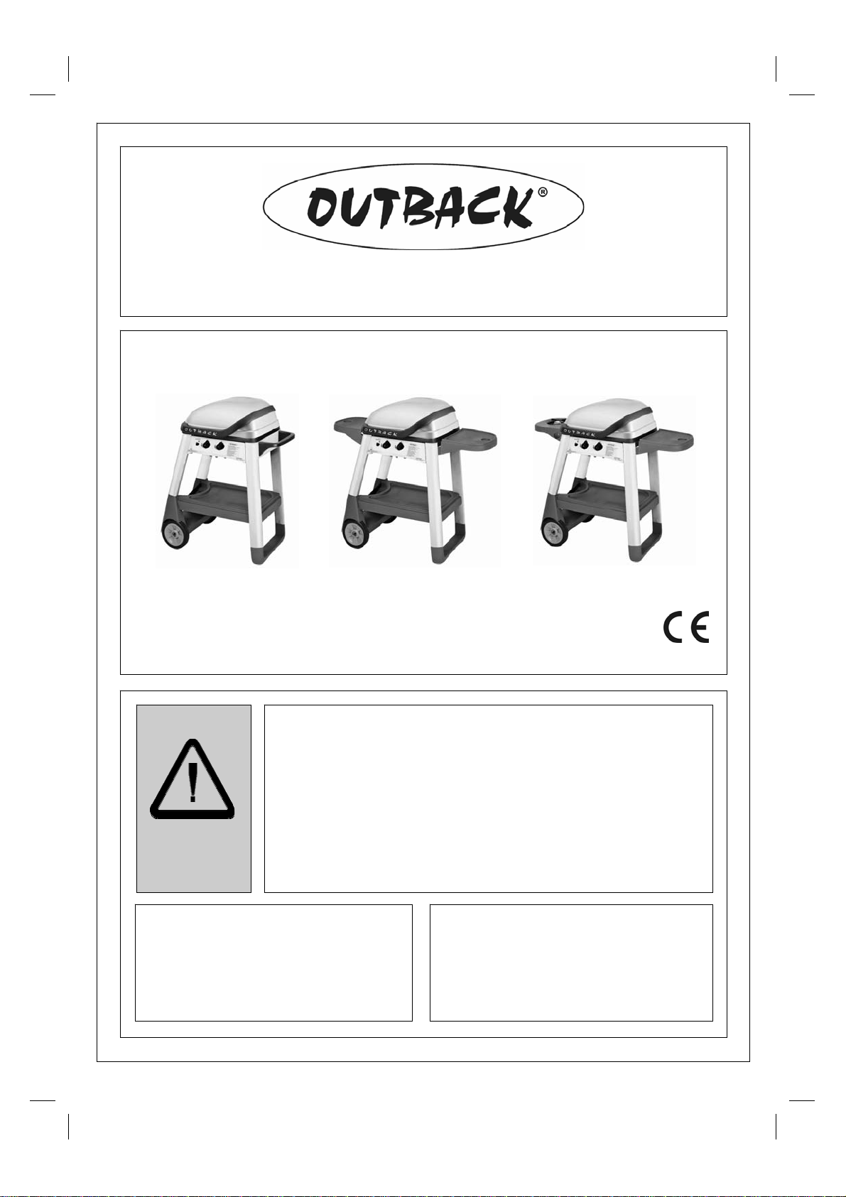
Gas Barbecues
Assembly an d Operati ng I nstruct ions fo r
Excel 100, Exc el 200, an d Excel 300 Gas Barbecues
Excel 100
Photographs are not to scale.
Specifications subject to change
without prior notice.
WARNING
• For outdoor use only. Not for commercial use.
• Read instructions before using the appliance. Failure to follow instructions could
result in death, serious bodily injury, and/or property loss.
• Warning: accessible parts may be very hot. Keep young children away.
• Do not m ove the appliance during use.
• Turn off the gas supply at the gas bottle after use.
• Any modification of the appliance, m is use, or failure to follow the instructions may
be dangerous and will invalidate your warranty. This does not affect your statutory
rights.
• Retain these instructions for future reference.
• Leak test your barbecue annually. Check the hose connections are tight and leak
test them each time you reconnect the gas bottle.
FOR YOUR SAFETY
If you smell gas:
1. Shut off gas to the appliance.
2. Extinguish any open flame.
3. Open barbecue lid or hood.
4. If odour continues, discontinue use and
contact your local dealer.
Excel 300 Excel 200
0694BR0014
FOR YOUR SAFETY
1. Do not store or use petrol or other flammable
vapours or liquids in the vicinity of this or any
other appliance.
2. A gas bottle not connected for use shall not be
stored in the vicinity of this or any other
appliance.
Page 2
A. P arts Li st
Quantities vary according to model purchased. Specifications subject to change without prior notice. For more
details on hardware, please see the corresponding Hardware Reference Diagram for your barbecue model.
OUTBACK® EXCEL RANG E
CODE PART QTY EXCEL 100 EXCEL 200 EXEL 300
Body
Assembly
Upper
Trolley
Lower
Trolley
Hardware
A1 Lava Rock Rack 1
A2 Burner 1
A3 Hood Lower Handle 1
A4 Hood 1
A5 Body 1
A6 Grease Cup Holder 1
A7 Grease Cup 1
A8 Cooking Grill 1
A9 Lava Rock (Shrink Packed) 1
A10 Hood Upper Handle 1
A11 Hinge Bracket 2
A12 Main Electrode & Gas Collector Box 1
A13 Heat Shield 1
A14 Warming Rack 1
A15 Sillcon Bumpers 2
A16 Body Support 2
B1 C ontro l P ane l 1
B2 Igniter Butto n 1
B3 Main Burner Knob 2
B4 Tro lle y Handle 1
B5 Main Burner Hose 1
B6 Side Shelf ▲ 2 1
B7 Side Burner Knob 1
B8 Side Burner Rack 1
B9 Side Burner Shelf 1
B10 Side Burner 1
B11 Side Burner Electrode 1
B12 Side Burner Valve/Hose Assembly 1
C1 Short Leg Front 1
C2 Short Leg Rear 1
C3 Gas Cylinder Holder 1
C4 Wheel 2
C5 Axle 1
C6 Leg End Loop 1
C7 Long Leg Front 1
C8 Long Leg Rear 1
C9 Bottom S helf 1
C10 Gas Bottle Strap 1
D1 M6x15 Bolt ▲ 24 28 28
D2 M5x10 Bolt 4
D3 M4x10 Bolt 1
D4 ST4.0x10 Screw 2
D5 ST4.8x15 Screw 2
D6 M8 Locknut 2
D7 M5 Keps Nut 2
D8 Wheel Spacer 2
D9 Shelf Spacer ▲ 8 4
√ √ √
√ √ √
√ √ √
√* √* √*
√* √* √*
√ √ √
√ √ √
√ √ √
√* √* √*
√* √* √*
√* √* √*
√ √ √
√ √ √
√ √ √
√ √ √
√ √ √
√ √ √
√* √* √*
√* √* √*
√
√* √* √*
√
√
√
√
√
√*
√ √ √
√ √ √
√ √ √
√ √ √
√ √ √
√ √ √
√ √ √
√ √ √
√ √ √
√* √* √*
√ √ √
√
√ √ √
√ √ √
√ √ √
√ √ √
√ √ √
Pre-Assembled
Quantity and specification varies according to model purchased.
2
Page 3
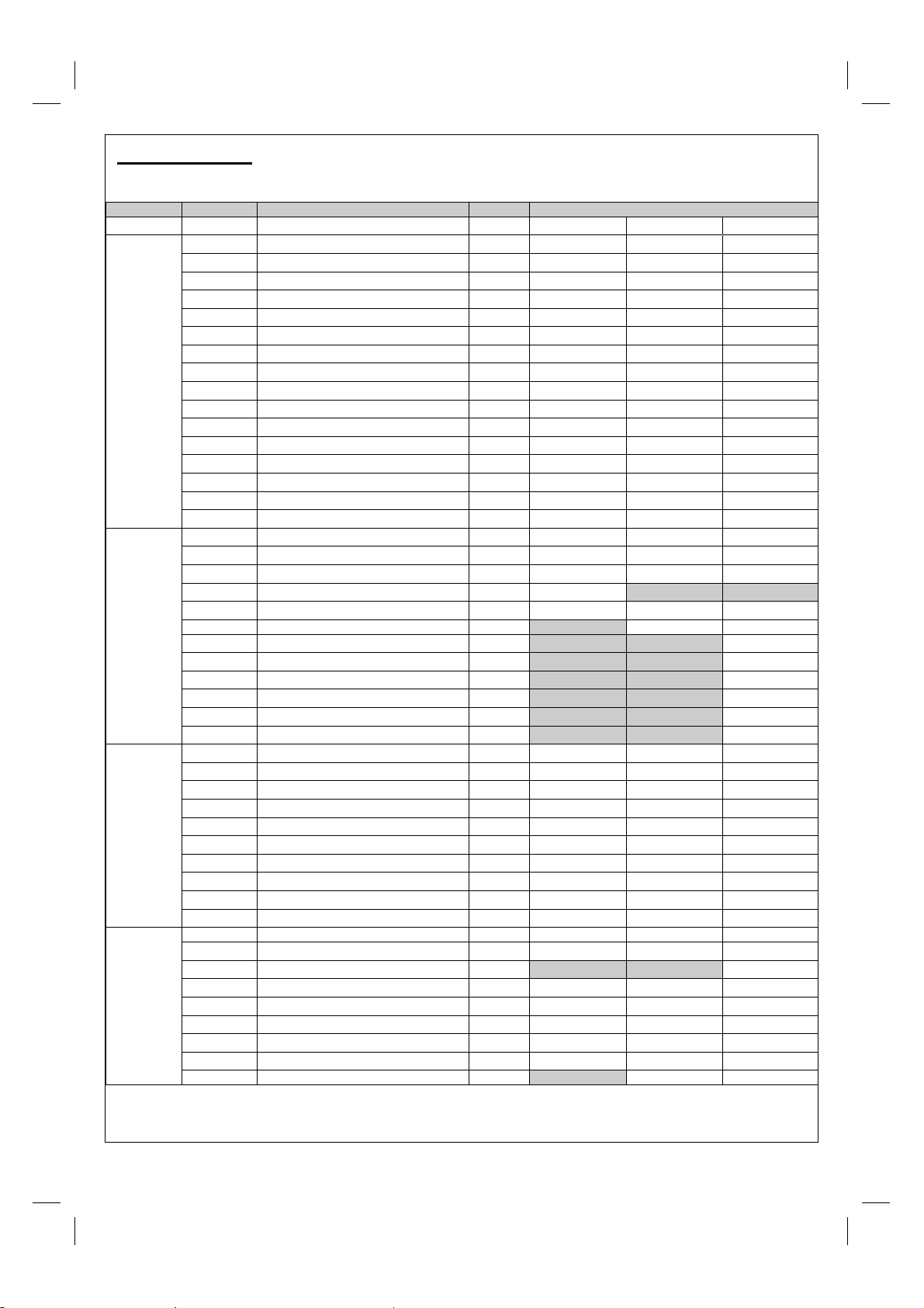
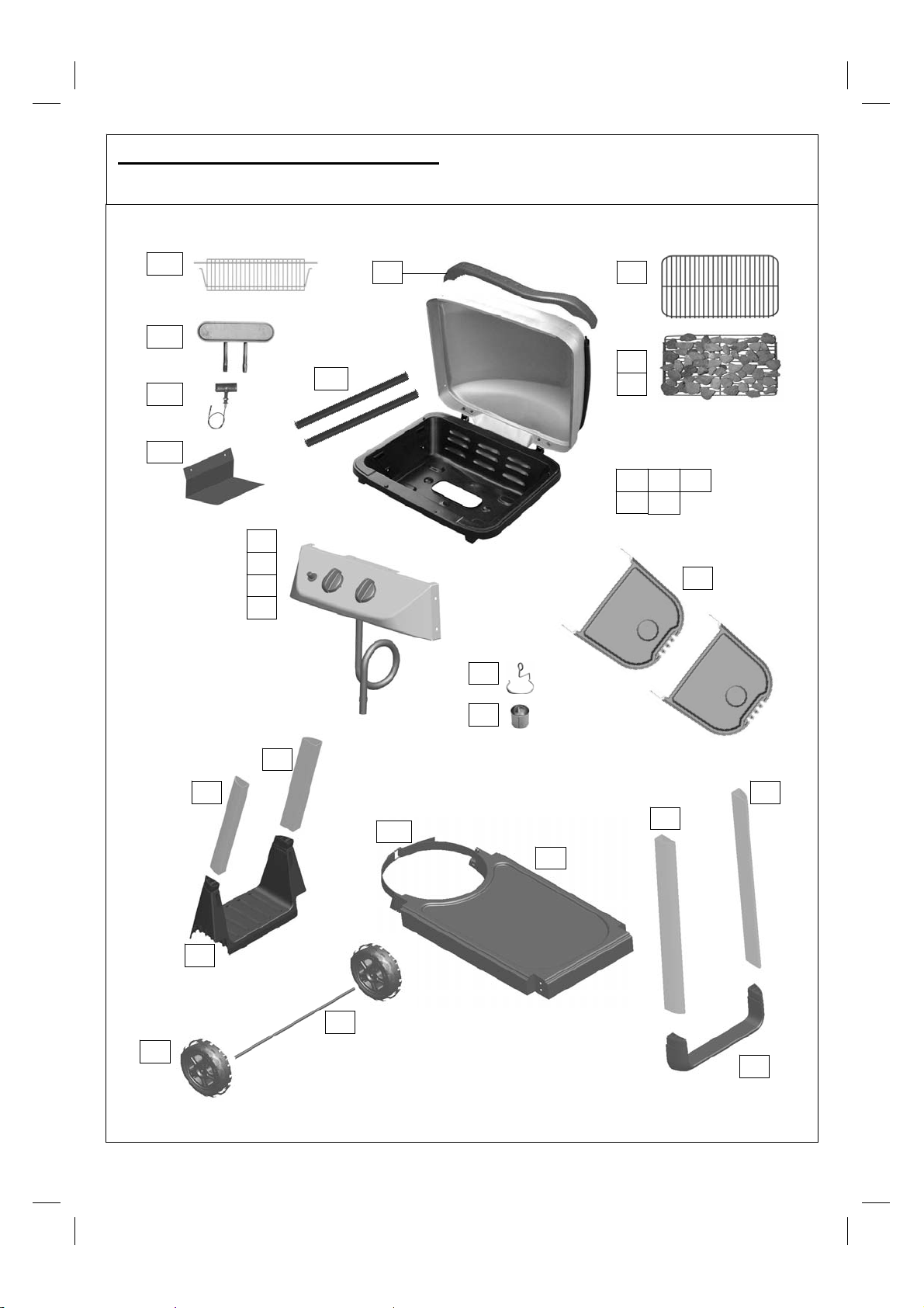
B1. P arts Diagram: Excel 100
Quantities vary according to model purchased. Specifications subject to change without prior notice. For more
details on hardware, please see ‘Hardware Reference Diagram: Excel 100.’
A14
A2
A12
A13
B1
B2
B3
B5
A16
A3
A8
A1
A9
Pre-assembled body unit
incl udes the fo llo wi ng
individual parts:
A4 A5 A10
A11 A15
B4
A6
C4
C1
C3
A7
C2
C8
C7
C10
C9
C5
C6
3
Page 4
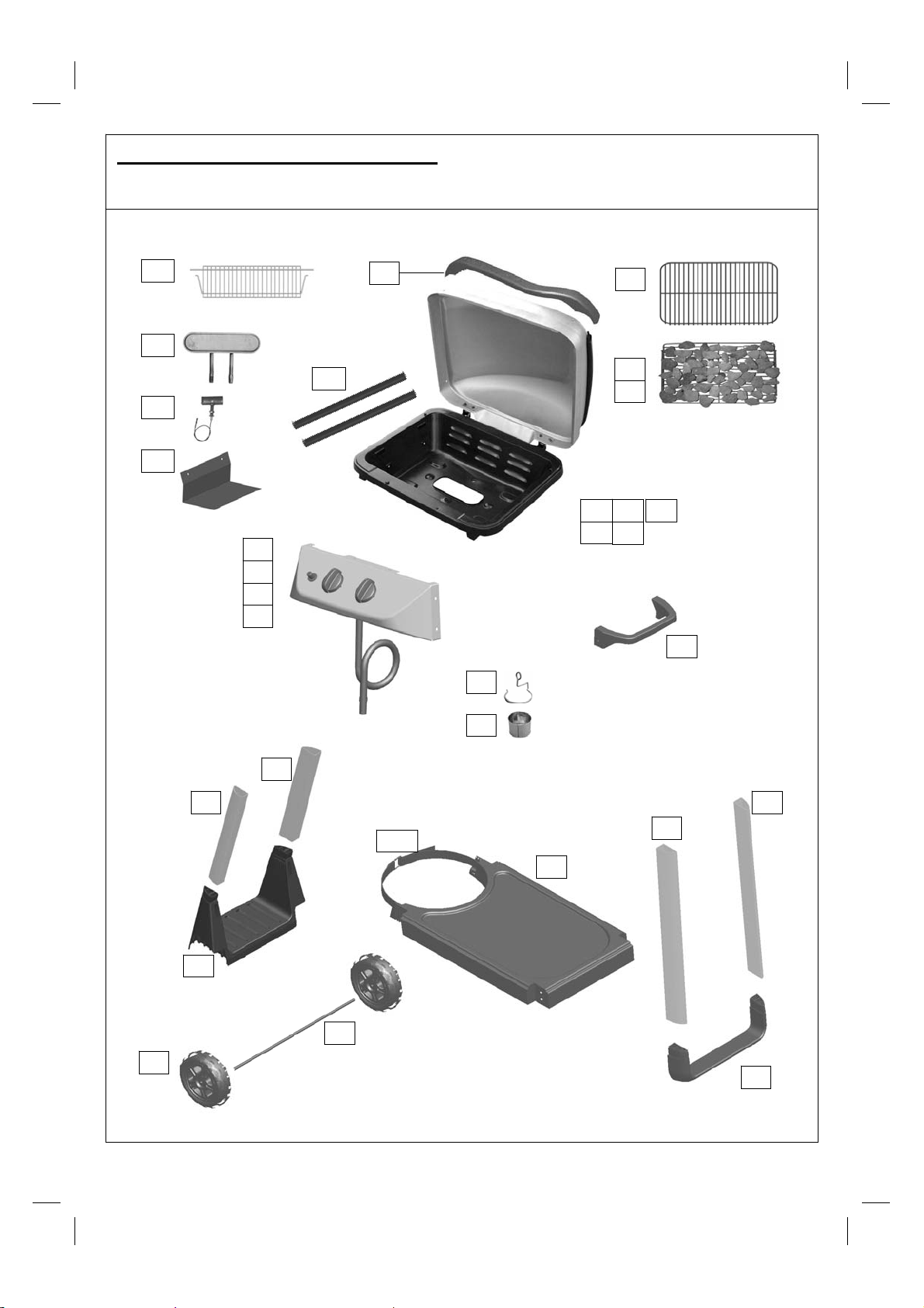
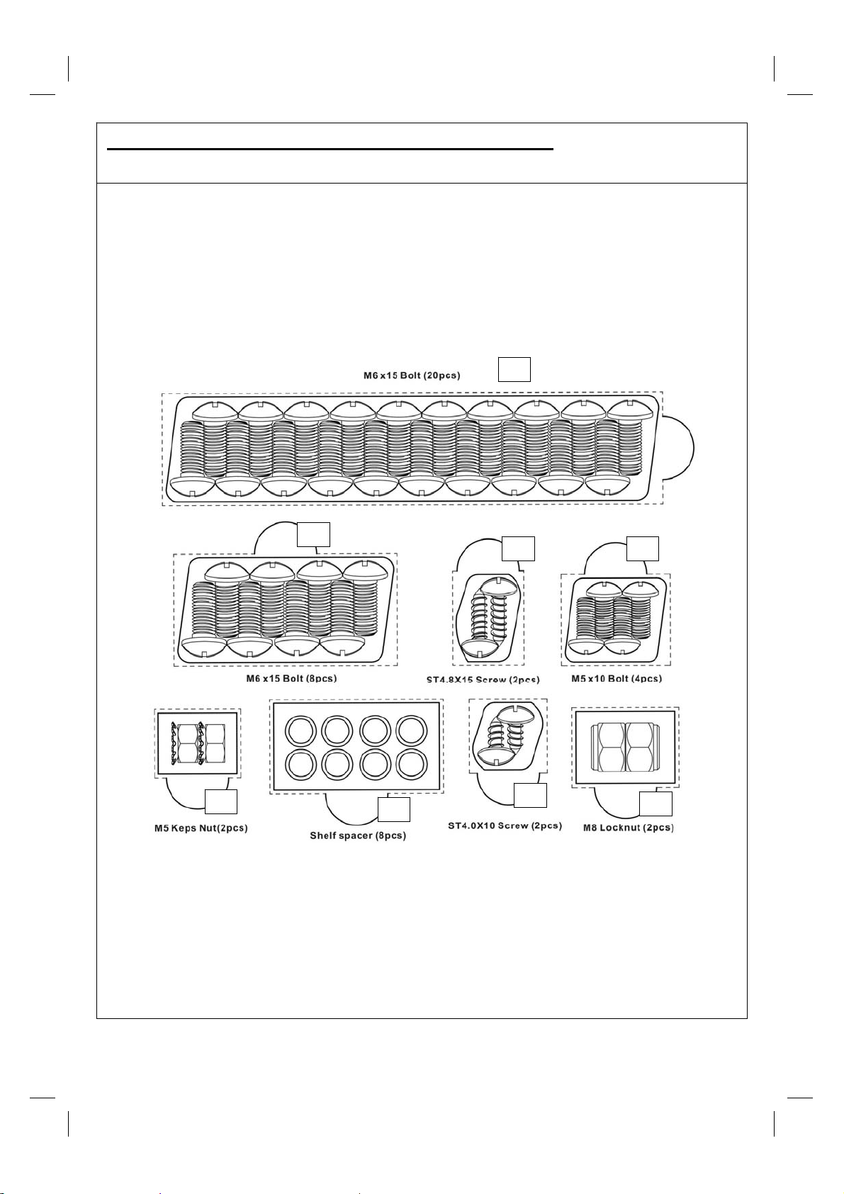
B2. Hardware Ref erence Diagram: Excel 100
Specifications subject to change without prior notice.
D1
D1 D4 D2
D5 D6 D7
4
Page 5
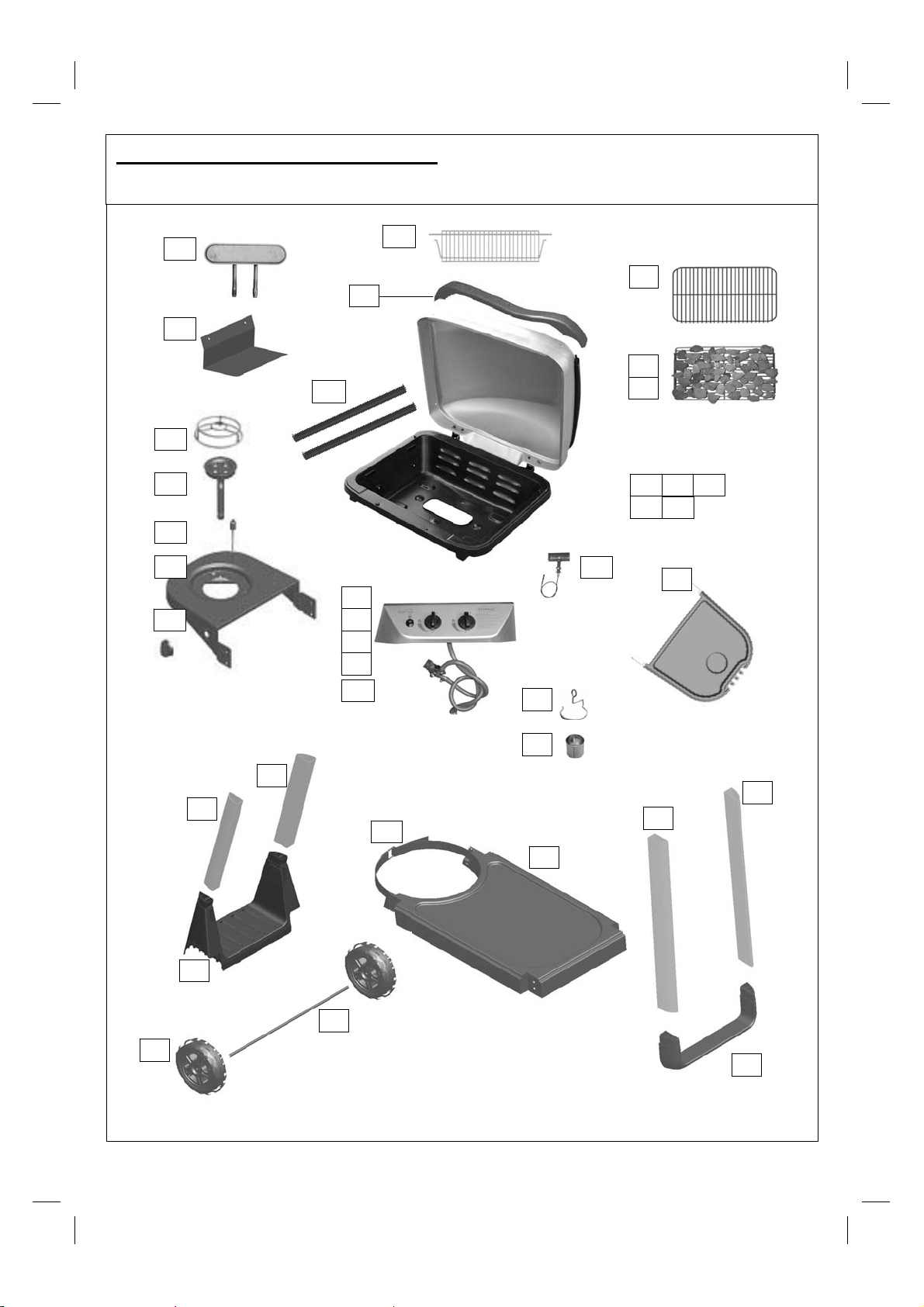
C1. Parts Di agram : E xcel 200
Quantities vary according to model purchased. Specifications subject to change without prior notice. For more
details on hardware, please see ‘Hardware Reference Diagram: Excel 200.’
A14
A2
A12
A13
B1
B2
B3
B5
A16
A3
A8
A1
A9
Pre-assembled body unit
incl udes the fo llo wi ng
individual parts:
A4 A5 A10
A11 A15
B6
A6
C4
C1
C3
A7
C2
C8
C7
C10
C9
C5
C6
5
Page 6
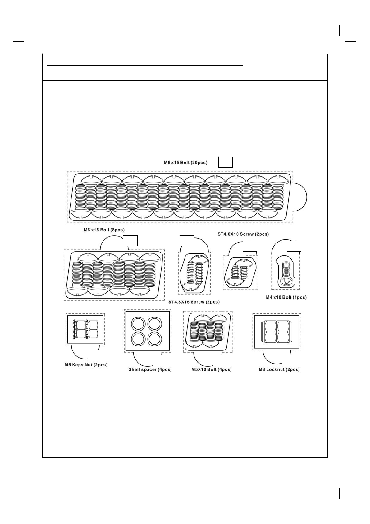
C2. Hardware R ef erence Diagram: E xcel 200
Specifications subject to change without prior notice.
D1
D1
D2 D5
D6
D9
6
D4
D7
Page 7
D1. Parts Di agram : E xcel 300
Quantities vary according to model purchased. Specifications subject to change without prior notice. For more
details on hardware, please see ‘Hardware Reference Diagram: Excel 300.’
A2
A13
B8
B10
B11
B9
B7
A16
A3
B1
B2
B3
B5
B12
A14
A8
A1
A9
Pre-assembled body unit
incl udes the fo llo wi ng
individual parts:
A4 A5 A10
A11 A15
A12
B6
A6
C4
C1
C3
A7
C2
C8
C7
C10
C9
C5
C6
7
Page 8
D2. Hardware R ef erence Diagram: E xcel 300
Specifications subject to change without prior notice.
D1
D7
D1 D5
D4 D3
D9 D2 D6
8
Page 9
E. A ssem bly
TOOLS NEEDED FOR ASSEMBLY:
Medium size flat blade or Philips/cross-point screwdriver, adjustable spanner or metric spanner set
This barbecue requires two people for assembly. Please remove all packaging materials from all
individual parts before assembling. Please lay out all nuts and bolts and check lengths before
assembling. Whilst every care is taken during the manufacture of this product, care must be taken
during the assembly in case sharp edges are present.
Excel 100 Excel 200 Excel 300
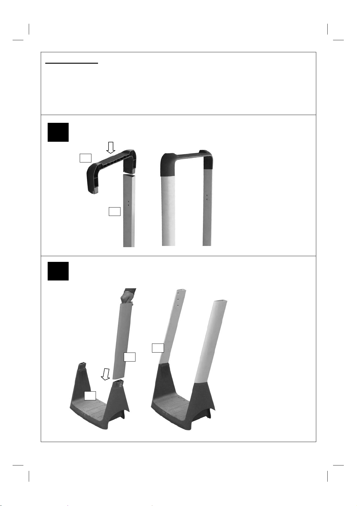
1
C6
Attach the Long Leg
Front (C7) and Long
Leg Rear (C8) to the
Leg End Loop (C6).
The legs are a push fit
C7
onto the Leg End Loop.
In case of difficulty, they
may need tapping with
a soft faced mallet.
Take care not to
damage the parts.
Excel 100 Excel 200 Excel 300
2
C2
C1
C3
Attach the Short Leg
Front (C1) and Short
Leg Rear (C2) to the
Gas Cylinder Holder
(C3). The legs are a
push fit onto the Gas
Cylinder Holder. In case
of difficulty; they may
need tapping with a soft
faced mallet. Take care
not to damage the
parts.
9
Page 10

Excel 100 Excel 200 Excel 300
3
Attach the Bottom Shelf (C9) to the Gas Bottle
Holder (C3) using the screws (D5). Taking care
not to over tighten.
C9
C3
Excel 100 Excel 200 Excel 300
4
Attach the leg assembly to the
Bottom Shelf assembly using the
screws (D1).
D5
10
D1
Page 11
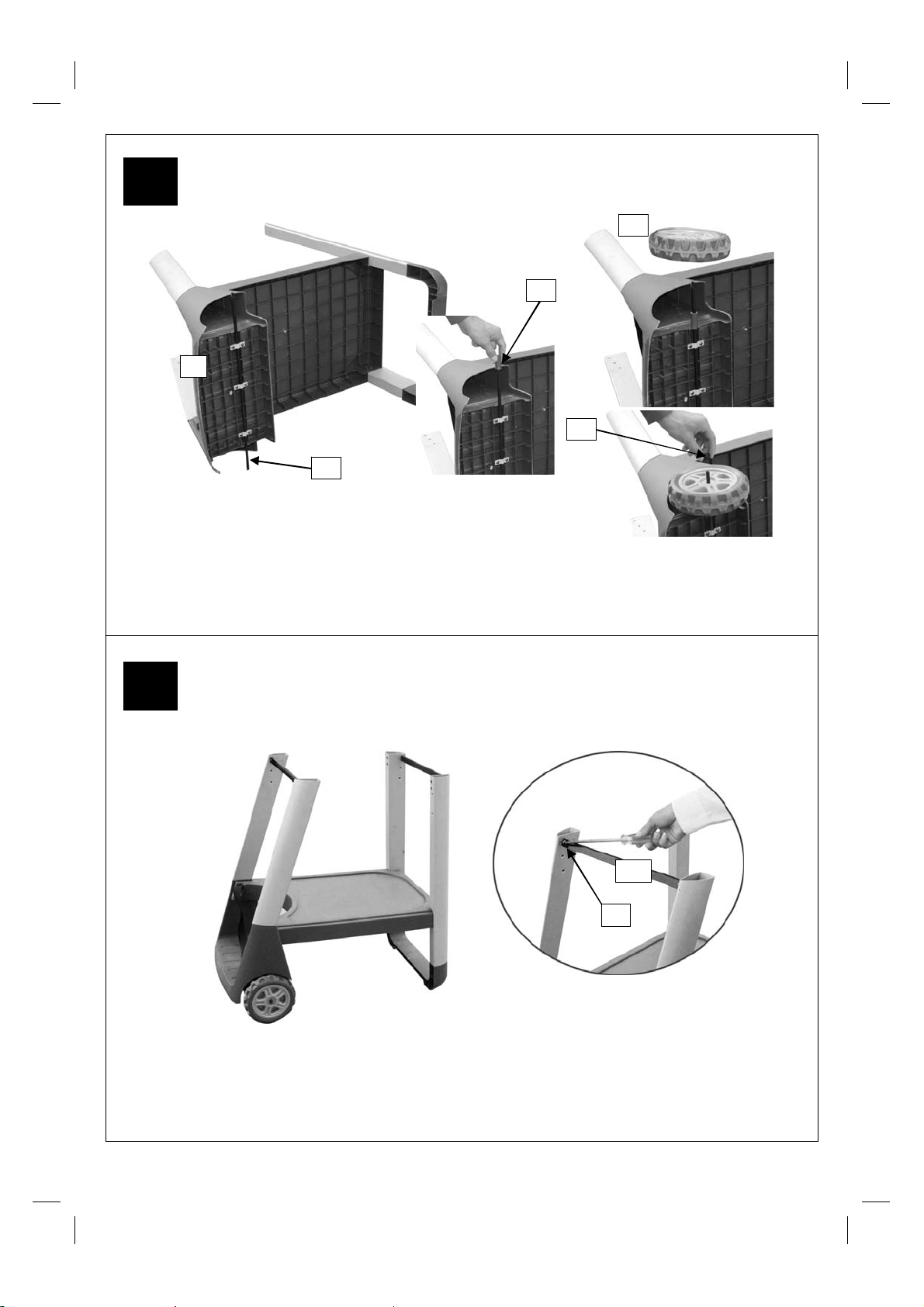
Excel 100 Excel 200 Excel 300
5
C4
D8
C3
D6
C5
Insert the axle (C5) through the clamping
brackets underneath the Gas Cylinder Holder
(C3) and tighten the clamping screws. Taking
care not to over tighten.
Slide a Wheel Spacer (D8) over the Axle (C5).
Slide a wheel (C4) and secure it
with a M8 Locknut (D6). Repeat for
the other side before standing it up.
Excel 100 Excel 200 Excel 300
6
A16
D1
Attach the Body Support (A16) to the
legs using the screws (D1).
Note: The securing tabs on the end of
the supports should face away from the
barbecue as shown in the diagram.
11
Page 12

Excel 100 Excel 200 Excel 300
7
Attach the Hood Lower Handle (A3) to the Hood
A3
A4
(A4) using the Screws (D2).
D2
Excel 100 Excel 200 Excel 300
8
A5
Attach the body (A5) to the Trolley
Assembly by sliding the fixing brackets
inside the tops of the legs and securing
with the screws (D1).
D1
12
Page 13

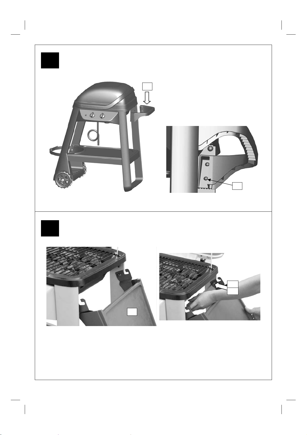
Excel 100 Excel 200 Excel 300
9
Attach the Control Panel Assembly to the Trolley Assembly using the Screws (D1).
10
Excel 100 Excel 200 Excel 300
A6
Insert the Grease Cup (A7) into the
Grease Cup Holder.
Feed the Grease Cup Holder (A6)
through the hole in the Body (A5).
A7
13
Page 14

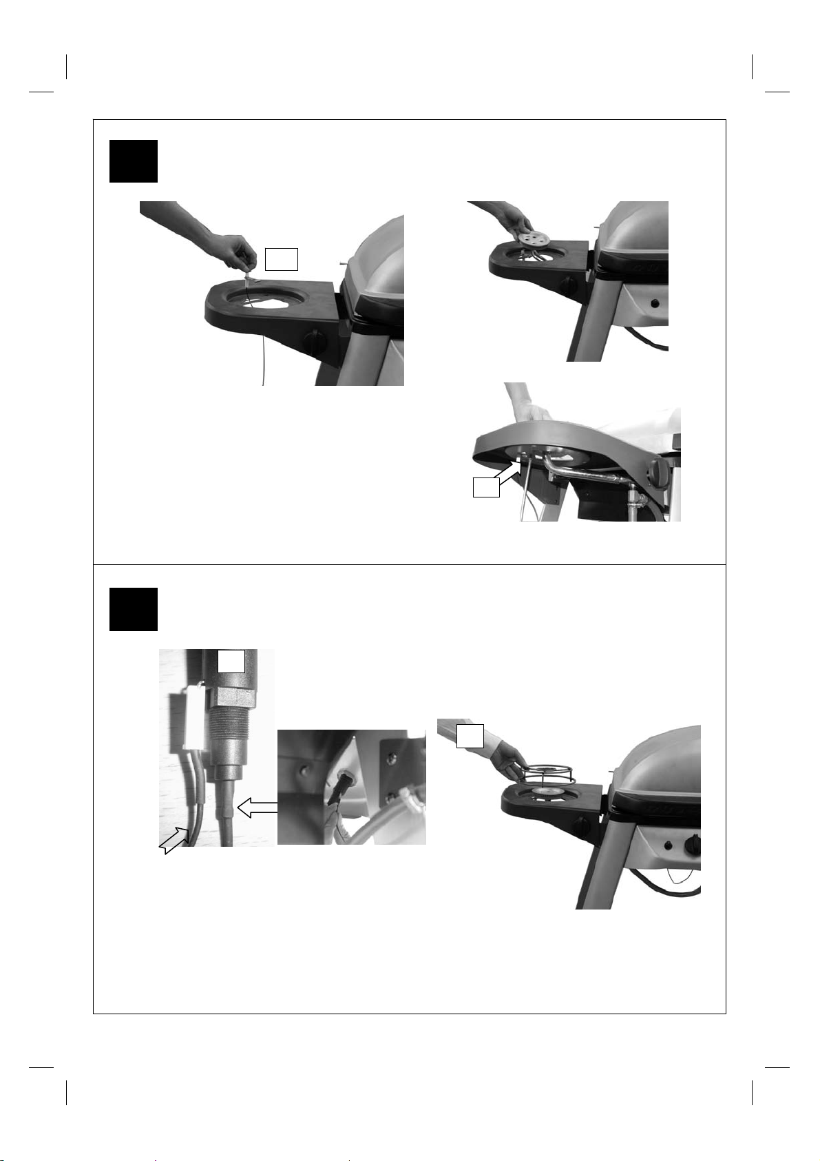
11
Excel 100 Excel 200 Excel 300
Remove the lower nut from the main electrode (A12) and insert the electrode with
the gas collector box into the hole in the bottom of the body. The open face of the
gas collector box must face towards the back of the barbecue body. Secure with
the nut removed earlier.
12
Excel 100 Excel 200 Excel 300
A2
Fit the Burner (A2) into the Body (A5)
ensuring the burner venturi tubes are over
the ends of the gas valves. They are a loose
fit and not a gas tight seal. Secure the
Burner with the Screws (D4);
D4
View looking underneath the body.
14
Page 15

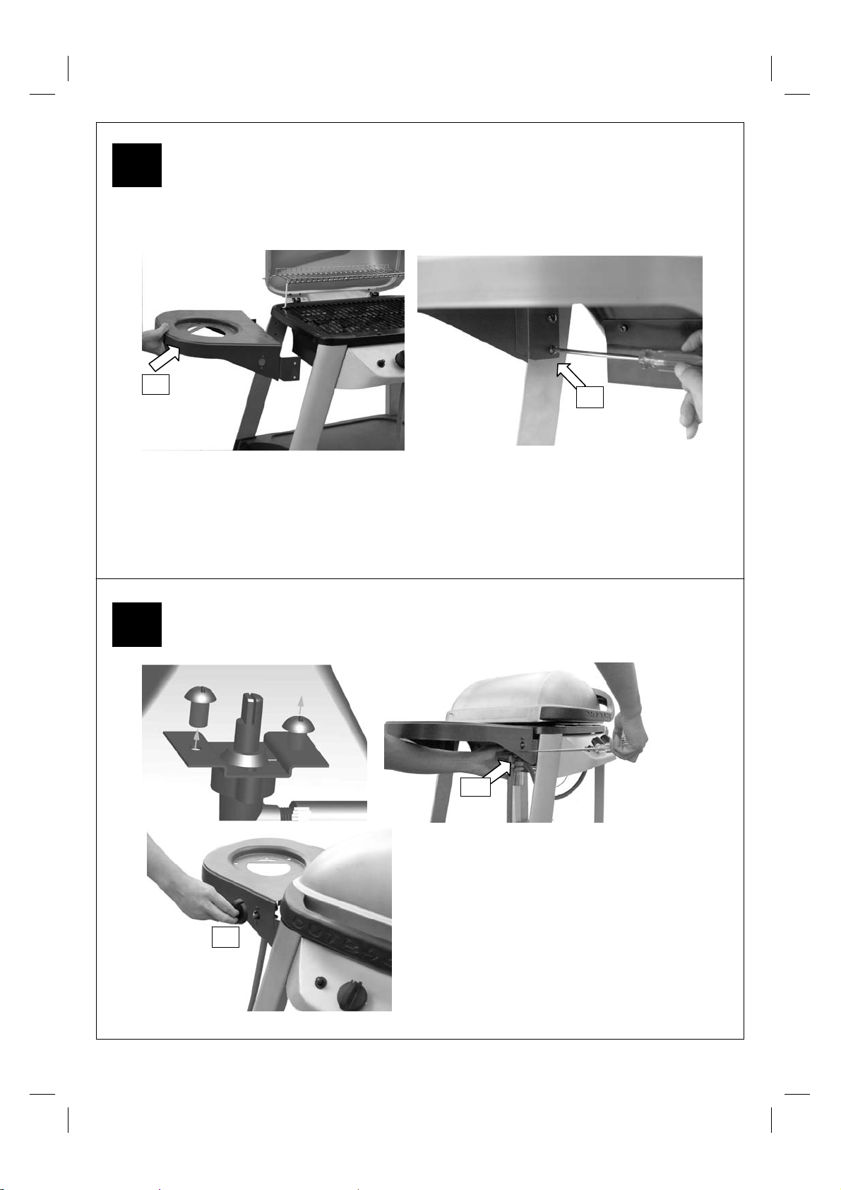
13
Excel 100 Excel 200 Excel 300
A13
Attach the Heat Shield (A13) to the Body (A5)
using the Screws (D2) and nuts (D7).
14
Excel 100 Excel 200 Excel 300
A8
A1
A9
Place the Lava Rock Rack (A1) and Lava
Rock (A9) into the body of the barbecue
A14
followed by the Cooking Grill (A8). Fit the
Warming rack (A14). Make sure the
swing legs fix to the body of the barbecue
and the shorter, fixed legs go through the
holes in the hood.
15
Page 16
15
Excel 100 Excel 200 Excel 300
16
B4
Attach the Trolley Handle (B4) to the
Long Legs using the screws (D1).
D1
Excel 100 Excel 200 Excel 300
D1
D9
B6
Attach a side shelf (B6) to the right hand side of the barbecue by sliding a shelf spacer
(D9) onto a screw (D1) and fit the shelf to the lower fixing point on the rear leg as shown.
Repeat for the front leg. Slide a shelf spacer (D9) onto a screw (D1) and screw it into the
upper fixing point on the rear legs as shown. Repeat for the front leg. For Excel 200 only,
repeat the above procedure for the left hand side shelf.
16
Page 17
17
Excel 100 Excel 200 Excel 300
B9
Attach the Side Burner Shelf (B9) to the Short Legs using the Screws (D1).
18
Excel 100 Excel 200 Excel 300
B12
D1
B7
Remove the screws from Side Burner
Valve/Hose Assembly (B12) and
secure it to the side shelf with those 2
screws;
Assemble the Side Burner Knob (B7)
onto the side burner valve.
17
Page 18
19
Excel 100 Excel 200 Excel 300
B11
Place the Side Burner Electrode (B11) onto
the side bur ner shelf as shown and place the
Side Burner (B10) through the central hole
and position the side burner venturi tube over
the side burner gas valve. Secure the
electrode and burner with Screw (D3).
Note: The side burner venturi tube is a loose
fit on the vale and not a gas tight seal.
D3
20
Excel 100 Excel 200 Excel 300
B2
Side burner electrode
wire goes here.
Connect the electrode
wire to the Igniter
Button (B2) under the
control pa nel.
Main burner
electrode wire
goes here.
Place the Side Burner Grid (B8) onto
the side burner shelf.
B8
ASSEMBLY IS NOW COMPLET E.
Important – the barbecue must not be used before being leak tested as detailed on P. 20
Proceed to the next page for operation and maintenance.
18
Page 19

F. Im portant Information
Please read these instructions carefully
befor e assembl y and use.
• Retain these instructions for future
reference.
• For outdoors use only – do not use
indoors. Do not use below ground level.
• For use with LPG bottled gas only. A
fixed pressure regulator of 28-30mbar
must be used for butane or 37mbar for
propane.
• Remove lava rock from plastic shrink
pack before lighting.
• Do not use within 1m of any flammable
structure or surface.
• LP gas cylinders should not be placed
directly underneath the barbecue.
• LP gas cylinders must not be stored or
used in the horizontal position. A leak
would be very serious and liquid could
enter the gas line.
• When igniting barbecue open its hood
before lighting.
• Do not move the barbecue while alight.
• This barbecue must not be left
unattended when lit.
• The hood handle can become very hot.
Grip only the centre of the handle. Use of
a cooking glove is advised.
• Use caution when opening the hood, as
hot steam inside is released upon
opening.
• Parts of this barbecue become very hot –
care must be taken when children, elderly
people, and animals are present.
• Always turn off the gas bottle when the
barbecue is not in use.
• Never c over a barbecue until it has
completely cooled.
• Never use the barbecue with the side
shelf in the down position.
• Leak test annually, and whenever the gas
bottle is removed or replaced.
• Do not store flammable materials near
this barbecue.
• Do not use aerosols near this barbecue.
• Failure to follow the manual’s instructions
could result in serious injury or damage.
• If you have any queries regarding these
instructions, contact your local dealer.
G. Gas a nd Regulator
This barbecue can use eith er propane or
butane LPG bottled gas. Propane bottles,
normally red coloured, will supply gas all year
round, even on cold winter days. A spanne r
may be required to change gas bottles. B utane
bottles, normally blue, will supply sufficient gas
in summer, but performance of the barbecue
may be affected once the gas temperatur e
starts to fall below +10°C. The bottle shoul d
never be stood on the trolley base and placed
directly under the barbecue . Gas bottles should
never be stored or used laid on t heir side.
Never store gas bottles i ndoors.
For optimal performance, we suggest the
following:
Model Butane Minimum
Outback®
Excel 100
Outback®
Excel 200
Outback®
Excel 300
Suitable regulators for butane must have an
outlet pressure of 28-30mbar. For propane, the
regulator must have a n outlet pressure of
37mbar. YOU MUST HAVE THE PROPER
REGULATOR AND B OTTLE IN ORDER FO R
THE BARBECUE TO OPERATE SAFELY AND
EFFICIENTLY. USE OF AN INCORRECT OR
FAULTY REGULATOR IS DANGEROUS AND
WILL INVALIDATE ANY WARRANTY. Please
consult your local gas deal er for the most
suitable gas bottles and regulators.
Bottle Size
6kg 3.9kg
6kg 3.9kg
15kg 6kg
Propane Minimum
Bottle Size
H. Installati on
H1. Selecting a Location
This barbecue is f or outdoor use only and
should be placed in a well-ventilated area. Take
care to ensure that it is not placed UNDER any
combustible surface. The sides of the barbecue
should NEVER be closer than 1 metre from any
combustible surface. Keep this barbecue away
from any flammable materials!
H2. Precautions
Do not obstruct any ventilat ion openings in the
barbecue body. Secure the gas bottle on the
cylinder holder and always tighten it with the
black strap provided. Should you nee d to
19
Page 20

change the gas bottle, confirm that th e
barbecue is switched off, and that there are n o
sources of ignition (cigarettes, open fla me,
sparks, etc.) near before proceeding. Inspect
the gas hose to ensure it is free of any twisting
or tension. The hose should hang freely with n o
bends, folds, or kinks that could obstruct fre e
flow of gas. Apart from the connection point, no
part of the hose should touch any hot barbecue
parts. Always inspect the hos e for cuts, cracks,
or excessive wear b efore use. If the hose is
damaged, it must be replaced with hose
suitable for use with LPG and meet the national
standards for the country of use. The length of
the hose shall not e xceed 1.5m. N. B.-Th e dat e
on U.K. orange hose is the date of
manufacture, not the expiry date.
H3. Fixing the Regulator to the Gas Bottle
Confirm all barbecue c ontrol knobs are in the
off position. Connect the regulat or to the gas
bottle according to your regulator and bottle
dealer’s instructions.
H4. Leak Testing (To be performed in a
well-ventilated area.)
Confirm all control knobs are in the off position.
Open the gas control valve on the bottle or
regulator. Check for leaks by brushing a
solution of ½ water and ½ soap over all g as
system joints, including all valv e connections,
hose connections and regulat or connections.
NEVER USE AN OPEN FLAME to te st for
leaks at anytime. If bubbles form over a ny of
the joints, there is a leak. Turn off the gas
supply and retighten all joints. Re peat test. If
bubbles form again , do not use the barbecue.
Please contact your local dealer for assi stance.
Leak test your barbecue a nnually. Check the
hose connections are tight and leak test them
each time you reconnect the gas bottle.
I. Op era t ion
I1. Warning
• Before proceeding, make certain that you
understand the IM PORTANT
INFORMATION s ection of this manual.
I2. Preparation Before Cooking
To prevent foods fro m sticking to the cooking
grill, please use a long handled bru sh to apply
a light coat of cooking or veget able oil before
each barbecuing session. (Note: When
cooking for the first tim e , paint colours m ay
change slig htly as a re sult. This is normal
and should be expected.)
I3. Lighting the Barbecue
• Open the barbecue hoo d.
• Ensure all knobs are in th e off position.
Open the gas control val ve on the gas
bottle or regulator.
• Push and turn the leftmost control kno b to
the high position. Press the igniti on button
rapidly several ti mes until left portion o f the
burner is lit. If burne r fails to ignite, turn
control knob to the off position and turn
gas off at the bottle or regul ator. Wait five
minutes, then repeat the above steps.
After successful lighting of the left sid e,
ignite the remaining portion of the burne r.
If the burner fails to ignite after fo llowing
above procedure, turn all the kn obs to the
off position. Close the gas valve on the gas
bottle. Wait 5 minutes, then repeat the
above steps. If the barbecue still fails to
light, please refer to the manual ignition
instructions in section be low.
• After ignition, the b urner should be burne d
at the high position for 3-5 minutes in ord er
to preheat the bar becue. This process
should be done before e very cooking
session. The hood (where applicable)
should be open during p reheating.
• After completion of preheating, the burn er
should normally be turned down to a lower
position for best cooking results.
I4. Manual Lighting Instructions
• Insert lit match through the match-lighting
hole underneath the barbecue.
• Push and turn the rightmost control kno b
anti-clockwise to the hig h position.
• After the right portion of the burner is lit,
light the remaining portio n of the burner.
• If burner fails to ignit e, contact your local
dealer for assistance.
• After ignition, the b urner should be burne d
at the high position for 3-5 minutes in ord er
to preheat the bar becue. This process
should be done before e very cooking
session. The hood (where applicable)
should be open during p reheating.
• After completion of preheating, the burn er
should normally be turned down to a lower
position for best cooking results.
I5. Warming Rack
Warming racks are a convenient way to keep
cooked food war m or to warm ite ms such as
bread rolls. Care should be taken to ensure
that any items placed on the warming rack are
cooked through and do not continue to co ok
and drip fat or meat juices, which could dri p
20
Page 21

onto the hood and dow n the back of the
barbecue.
I6. Grill Cooking
The burner heats up th e lava rock underneath
the grill, which in turn heats the food on the
grill. The natural food juices produced during
cooking fall onto the hot lava rock below an d
vaporise. The subsequent risi ng smoke bastes
the food, as it travels upwards, imparting that
unique barbecued flavour.
When using your barbecue for grill c ooking,
you may wish to place the hood in the closed
position which will hold the heat in and give
more even cooking of the food. This should
only be done wit h the burner turned down to a
lower setting.
I7. Roasting Hood Cooking
Barbecues equipped with a ro asting hood give
the option of cooking with hood clo sed to form
an ‘oven’ for roasting food, such as joints of
meat, whole chickens, et c.
When roasting, turn the burner under the food
to the OFF position. Cl ose the hood and turn
the other burner down to a lower setting i.e. lo w
to medium to achieve the temperature required.
DO NOT ALLOW YOUR BARBECUE TO
OVERHEAT. Avoid lifting the hoo d
unnecessarily as heat is lost each time the
hood is opened.
I8. Side-Burner Cooking
When using the side-burner, care should be
taken to ensure that pans are c entral and flat
on the side-burner grid.
I9. Flare-Up Control
Flare-ups occur when meat is barbecued, an d
its fat and juices fall upo n the hot lava rock.
Smoke helps give food its barbecued f lavour,
but avoid excessive flare-up to prevent foo d
being burned. To control flare-up, it is advisable
to trim away excess fat from meat and poultry
before grilling. The burner sh ould be turned
down to a lower setting to reduce fl are-up.
Flare-ups can be extinguished by a pplying
baking soda or salt directly onto the la va rocks.
Always protect your hands when h andling
anything near the cooki ng surface of the
barbecue.
I10. End of Cooking Session
After each cooking s ession, turn the barbecu e
burner to the “ high” position and burn for 5
minutes. This procedure will burn off cooking
residue, thus making cleanin g easier. Make
sure the hood is open d uring this process.
I11. Turning Off Your Barbecue
When you have fi nished using your bar becue,
turn all the contro l valves fully clockwis e to the
“Off” position, then switch off the gas at the
bottle. Wait until the barbecue is sufficiently
cool before closing its h ood.
J. CARE AND M AINTENANCE
Regularly clean your barbecue between uses
and especially after extended perio ds of
storage. Ensure the barbecue and its
components are sufficiently cool before
cleaning. Do not leave the barbecue exposed
to outside weather conditions o r stored in
damp, moist areas.
• Never douse t he barbecue with water when
its surfaces are hot.
• Never handle hot p arts with unprotected
hands.
In order to extend the life and maintain the
condition of your barbecue, we strong ly
recommend that the uni t be covered when left
outside for any length of time, especially during
the winter months. Heavy-duty Outback®
barbecue covers and oth er accessories are
available from you local Outback® stockist.
Even when your barbecu e is covered for its
protection, it must b e inspected on a regul ar
basis as damp or condensation can fo rm which
may result in damage to the barbecue. Any ru st
that is found that does not come into contact
with the food should be trea ted with a rust
inhibitor and painted with barbecue paint or a
heat resistant paint. Chrome plated war ming
racks should be coated with cooking oil.
J1. Cooking Grill
Clean with hot soapy water. T o remove any
food residue, use a mild cream cleaner on a
non-abrasive pad. Rinse well and d ry
thoroughly.
J2. Burner Maintenance
Your burner has been preset f or optimal flame
performance. You wil l normally see a blu e
flame, possibly with a small yellow tip when the
burner is alight. If the flame pattern is
significantly y ellow, this could be a problem
caused by grea se from cooking blocking the
21
Page 22

burner or spiders or other insects in the burn er
venturi. This can resu lt in the flow of the g as
and air mixture being restricted or blocked
which may result in a fire behind the contr ol
panel causing serious damage to yo ur
barbecue. If th is hap pe ns, the gas should be
imme diate ly turne d off at the bottle . Burners
should be inspected and cleaned on a regul ar
basis in addition to the f ollowing conditions:
1) Bringing the barbecue o ut of storage.
2) One or more of the burn ers do not ignite.
3) The burner flame patter n is significantly
yellow.
4) The gas ignites behind t he control panel.
To clean a burner, remove it from the
barbecue. The outside of the burner can b e
cleaned with a w ire brush. Clean the portholes
with a pipe cleane r or piece of wire. Take care
not to enlarge the porth oles.
Clean the insect screen on the end of the
venturi tube with a bristle brush (i.e. an old
toothbrush).
Clean the venturi tube with a pipe cleaner or
piece of wire. Yo u may need a torch to see into
the venturi tube to make s ure it is clear. ”Turn
the burner up on end a nd lightly tap against a
piece of wood to dislodge any debris from
inside.”
Ventur i tube
J3. Lava Rock
It is not necessary to remove and wash the
lava rock in order to ke ep it clean. Burning off
the residue after e ach cooking should b e
sufficient. Heavily impregnat ed lava rock
should be turned over so that the dirty side
faces the burners in order t o burn off any
residue. Replacement lava r ock is available
from your local Outback ® stockist.
J4. Barbecue Body
Regularly remove e xcess grease or fat from the
barbecue body with a soft plastic or woode n
scraper. It is not necessary to remove all the
grease from the body. If you need to clean fully,
use hot soapy water and a cloth, or nylonbristled brush only. Remove cooking surfac es
and burners before full cle aning. Do not
immerse the gas controls or manifold in water.
Check burner operation af ter carefully refitting
into body. Check the gr ease cup and clean out
any grease that has drai ned into it.
J5. Fixings
All screws and bolts, etc. sho uld be checked
and tightened on a regul ar basis.
J6. Storage
Store your barbecue in a cool dry place. It must
be inspected on a regular basis as da mp or
condensation c an form which may result in
damage to the barbecue. It may be necessary
to dry the barbecue and th e inside of the cover
if used. Mould ca n grow under these conditions
and should be cleaned and tre ated if required.
Any rust that is found t hat does not come into
contact with the foo d should be treated with a
rust inhibitor and painted with barbecue paint or
a heat resistant paint. Chro me plated warming
racks and grills should be c oated with cooking
oil. Wrap the bur ners in aluminium foil to help
prevent insects or other debris fro m obstructing
the burners.
The gas bottle must be always be disconnected
from the barbecue and stored in a well
ventilated area at least 1 metre away from any
fixed ignition source. Do not store insid e
residential accommodation. Never stor e
cylinders below ground level ( e.g. cellars). Do
not let children tamper w ith bottles.
K. Technical Specificatio ns
Outback®
Excel 100
Outback®
Excel 200
Outback®
Excel 300
Side
Burner
Gas Consumption:
Excel 100: 446g/hr
Excel 200: 446g/hr
Excel 300: 446g/hr
Side Burner: 165g/hr
Countries of Use:
I
3+ (28-30/37)
ES, CH, GB, RO
BG, CY, CZ, DK, EE, FI, GR, LV, LT, LU, MT, NL, NO, SK,
I
3B/P(30)
SI, SE, TR, IS
AT, DE, HU, SK, CH
I
3B/P(50)
PL
I
3B/P(36)
Specifications are s ubject to change without prior
CE
Appr oval
0694
BR0014
0694
BR0014
0694
BR0014
0694
BR0014
BE, CY, C Z, EE, FR, GR, IE, IT, LV, LT, LU, PT, SK,
Heat
Burners
Input
6.2kW 1
6.2kW 1
6.2kW 1
2.3kW 1 0.74mm
Injector
Size
0.89mm
Gas /
Pressure
Butane/
28-30mbar
Propane/
37mbar
22
Page 23

L. Tr oub le s hoot i ng
Problem Possible Cause Solution
Bu rn ers wil l no t li gh t usin g
the ignition system
Faulty reg ulator Have regulator checked or replaced
Obstructio ns in burn ers Clean bu rners
Obstructions in gas jets or gas hose Clean jets and gas hose
Electrode wire is loose or dis connected
Electrode or wire is damaged Change electrode and wire
Faulty pushbutton ignitor Ch ange ignit or
Burner will not light with a
match
Faulty reg ulator Have regulator checked or replaced
Obstructio ns in burn ers Clean bu rners
Obstructions in gas jets or gas hose Clean jets and gas hose
Lo w fl a me or fl as hb ac k
(fire in burner tube— a
hissing or roaring noise
may b e h ear d)
Obstructio ns in burn ers Clean bu rners
Obstructions in gas jets or gas hose Clean jets and gas hose
Windy condit ions Use BBQ in a more sheltere d position
Gas val ve k no b di ff ic ul t to
turn
LP gas bottle is empty Replac e with full bott le
Reconn ect wire
on electrode or ignition unit
LP gas bottle is empty Replace with full bottle
LP gas b ottle too small Use larger bottle
Gas valve ja mmed Replac e gas valve
For reference and correspondence,
record your serial number here.
(See sticker on side of barbecue body.)
Serial No.__________________
This number may be required when
ordering spare parts or accessories. A
part reference number may also be
required where applicable.
23
Page 24

OUTBACK UK LTD
WARRANTY
OUTBACK barbecues are warranted to the original purchaser against defects in materials and
workmanship for a period of one (1) year from the date of purchase. OUTBACK UK will, within
this period, supply replacements for defective parts free of charge provided that:
♦ The product has not been used for trade, professional or hire purposes.
♦ The product has not been subjected to misuse or neglect, including fat fires and flare ups
or use of a faulty or incorrect regulator.
♦ The product has not sustained damage through foreign objects, substances or accidents.
♦ The care and maintenance instructions given in your Outback manual have been followed.
This warranty is offered as an extra benefit and is in addition to the customers’ statutory rights.
Outback UK does not warranty in any way the gas cylinder.
If you have any queries regarding the assembly or use of your barbecue please contact
Outback UK
In the unlikely event that you experience
problems with this barbeque, please contact:
e-mail: customerservice@outbackuk.com
Customer Service
Outback UK
Unit 2 Farleigh Hill
Tovil
Maidstone
Kent ME15 6RG
Tel: 01622 671771
Fax: 01622 673101
website: www.outbackuk.com
24
Published December 2007
 Loading...