

Page 1
DOM-OBK03 Rev. A
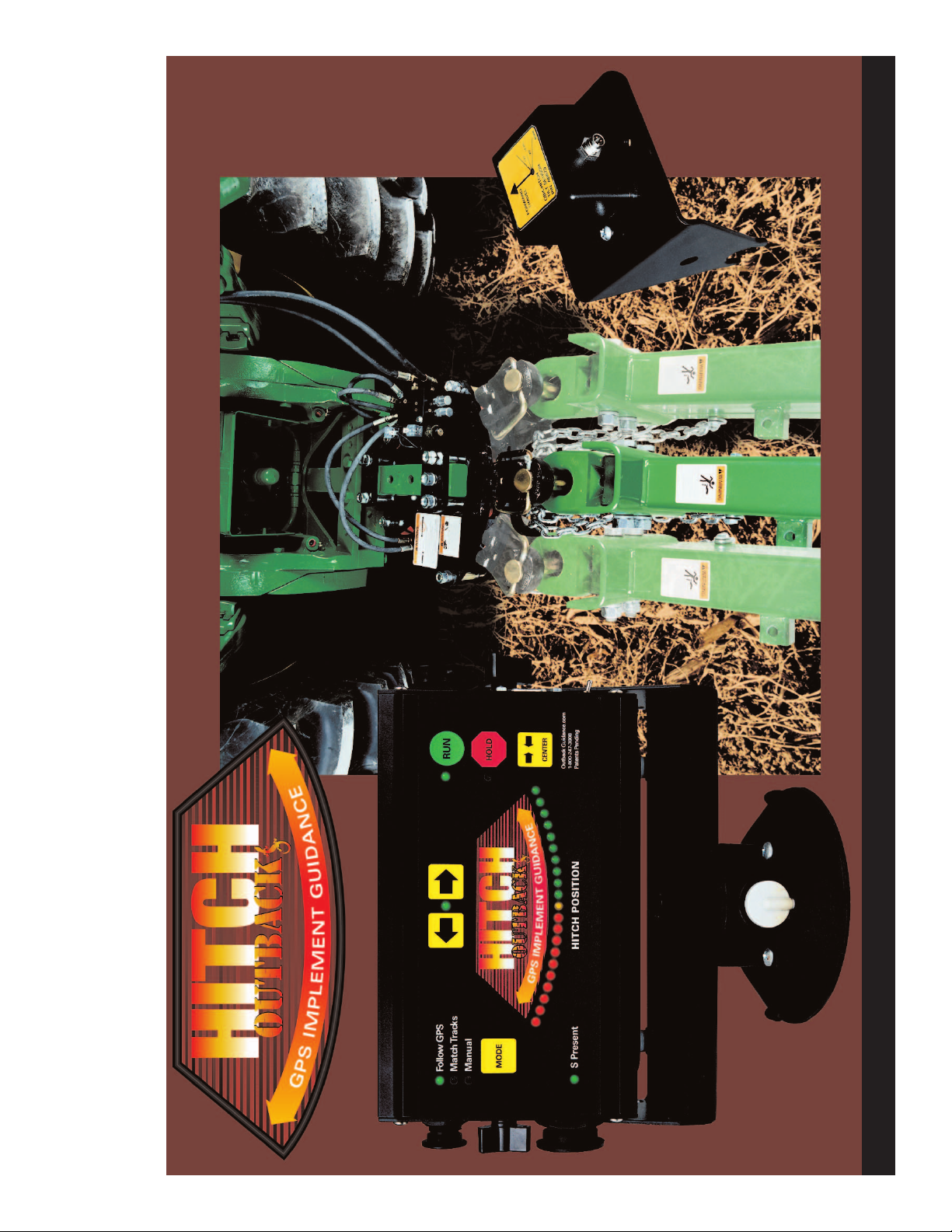
OUTBACK
HITCH OWNER’S MANUAL
Effective January, 2003
Last Edit May, 2003
Page 2

Page 3

G
P
S
I
M
P
L
E
M
E
N
T
G
U
I
D
A
N
C
E
®
1
Introduction . . . . . . . . . . . . . . . . . . . . . . . . . . . . . . . . . . . 1
Definitions of Safety and Service Statements . . . . . . . . 2
Specifications . . . . . . . . . . . . . . . . . . . . . . . . . . . . . . . . . 3
Safety Sign Locations and Care . . . . . . . . . . . . . . . . . . 4
Safety Information . . . . . . . . . . . . . . . . . . . . . . . . . . . . . 5
Installation . . . . . . . . . . . . . . . . . . . . . . . . . . . . . . . . . . . . 6
Tractor Preparation . . . . . . . . . . . . . . . . . . . . . . . . . . . . 6
Mounting the Hitch . . . . . . . . . . . . . . . . . . . . . . . . . . . . 7
Mounting the Tilt Sensor . . . . . . . . . . . . . . . . . . . . . . . 9
Routing the Hitch Control Cable . . . . . . . . . . . . . . . . . . 9
Mounting the Console . . . . . . . . . . . . . . . . . . . . . . . . . 10
Console Cable Connections . . . . . . . . . . . . . . . . . . . . 11
Get Acquainted with the Controls . . . . . . . . . . . . . . . . 12
Power Up . . . . . . . . . . . . . . . . . . . . . . . . . . . . . . . . . . . . 13
Setup . . . . . . . . . . . . . . . . . . . . . . . . . . . . . . . . . . . . . . . 13
Hitch Pin Position Calibration . . . . . . . . . . . . . . . . . . . 13
Curvature Compensation . . . . . . . . . . . . . . . . . . . . . . 13
Slope Compensation . . . . . . . . . . . . . . . . . . . . . . . . . . 13
Operation . . . . . . . . . . . . . . . . . . . . . . . . . . . . . . . . . . . . 14
Manual Mode . . . . . . . . . . . . . . . . . . . . . . . . . . . . . . . . 14
Follow GPS Mode . . . . . . . . . . . . . . . . . . . . . . . . . . . . 14
Match Tracks Mode . . . . . . . . . . . . . . . . . . . . . . . . . . . 14
This manual has been prepared to assist you in the
operation and maintenance of your OUTBACKHitch
Drawbar Implement Guidance System and to provide the
necessary part numbers to keep it in near original condi-
tion.
OutbackHitch Serial Number_____________________
Congratulations on your purchase of an OUTBACK
Hitch Drawbar Implement Guidance System. We at RHS
wish to thank you for your patronage and appreciate your
confidence in OUTBACKequipment. Your OUTBACK
Hitch has been carefully designed and ruggedly built to
provide many years of dependable service in return for
your investment.
TABLE OF CONTENTS
INTRODUCTION
Maintenance . . . . . . . . . . . . . . . . . . . . . . . . . . . . . . . . . 15
Initial Installation . . . . . . . . . . . . . . . . . . . . . . . . . . . . . 15
Grease Fittings . . . . . . . . . . . . . . . . . . . . . . . . . . . . . . 15
Replace Worn Components . . . . . . . . . . . . . . . . . . . . 15
Trouble-Shooting Tips . . . . . . . . . . . . . . . . . . . . . . . . . 15
Contacting the Factory . . . . . . . . . . . . . . . . . . . . . . . . . 16
Outback Warranties . . . . . . . . . . . . . . . . . . . . . . . . . . . 17
Appendix A - Parts Listings . . . . . . . . . . . . . . . . . . . . . . .
Outback-Hitch Drawbar Guidance System . . . . . . . . . A1
Console Mounting Details . . . . . . . . . . . . . . . . . . . . . . A2
Tilt Sensor Mounting Details . . . . . . . . . . . . . . . . . . . A2
Hydraulic & Electrical Assembly . . . . . . . . . . . . . . . . . A3
Mechanical Assembly . . . . . . . . . . . . . . . . . . . . . . . . . A4
Drawbar Sub-Assembly . . . . . . . . . . . . . . . . . . . . . . . A5
Hydraulic Component Details. . . . . . . . . . . . . . . . . . . . A6
Mounting Hardware Details . . . . . . . . . . . . . . . . . . . . . A7
Clevis Hitch Attachment [Optional]. . . . . . . . . . . . . . . . A8
Footnotes: OUTBACK and OUTBACK Guidance are registered trademarks of RHS, Inc. OUTBACK Guidance Center, Steering Guide, and Hitch are proprietary
trademarks of RHS, Inc. The OUTBACKS and OutbackHitch are protected under U.S. Patent No. 6,539,303 and patents pending.
Page 4
G
P
S
I
M
P
L
E
M
E
N
T
G
U
I
D
A
N
C
E
®
2
Definitions of Safety and Service Statements
TAKE NOTE! THIS SAFETY ALERT SYM-
BOL FOUND THROUGHOUT THIS MANU-
AL IS USED TO CALL YOUR ATTENTION
TO INSTRUCTIONS INVOLVING YOUR
PERSONAL SAFETY AND THE SAFETY
OF OTHERS. FAILURE TO FOLLOW
THESE INSTRUCTIONS CAN RESULT IN
INJURY OR DEATH.
!
THIS SYMBOL MEANS
- ATTENTION!
- BECOME ALERT!
- YOUR SAFETY IS INVOLVED!
All safety statements in this manual, as well as those
found on safety decals, are preceded by the following
warning symbols. Carefully read and follow the instruc-
tions provided.
Indicates an imminently hazardous situation
that, if not avoided,
will result in death or
serious injury. This signal word is to be limited to
the most extreme situations typically for machine
components which, for functional purposes, cannot
be guarded.
Indicates a potentially haz-
ardous situation that, if not
avoided, could result in
death or serious injury and
includes hazards that are exposed when guards are
removed. It may also be used to alert against unsafe
practices.
Indicates a potentially haz-
ardous situation that, if not
avoided, may result in
minor or moderate injury.
It may also be used to alert against unsafe practices.
The IMPORTANT notice gives
important instructions to prevent
damage to the machine or systems.
A Note will give general information
about the correct operation and
maintenance of the machine and systems.
DANGER:
!
WARNING:
!
CAUTION:
!
IMPORTANT:
NOTE:
Page 5
G
P
S
I
M
P
L
E
M
E
N
T
G
U
I
D
A
N
C
E
®
3
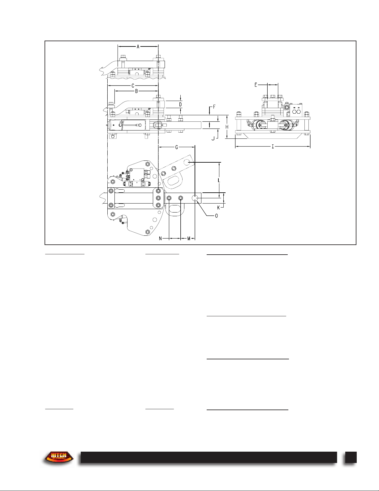
Specifications
Dimensions: Inch (mm)
(A) Min. Long Drop Clearance 11.5 (292)
(B) Max. Short Drop Clearance 12.25 (311)
(C) Min. Mounting Clearance 14.25 (362)
(D) Tractor Drawbar Thick. Range 1.5 - 2.0 (38 - 51)
(E) Tractor Drawbar Width Range 2.25 - 3.25 (64 - 83)
(F) Hitch Pin Point Below Tractor 1.75 (46)
(G) Hitch Pin Point Behind Tractor 10.25 (260)
(H) Hitch Clearance Below Tractor 6.5 (165)
(I) Hitch Overall Width 21 (534)
(J) Hitch Drawbar Thickness 2.0 (51)
(K) Hitch Drawbar Width 3.0 (76)
(L) Hitch Drawbar Swing ±10.0 (±254)
(M) Hitch Pin to Rear Clevis Hole 4.0 (102)
(N) Hitch Clevis Hole Spacing 3.25 (83)
(O) Hitch Pin Hole Diameter 1.67 (42)
Weights: Lbs (Kg)
Hitch Assy. (less mount. hardware & clevis) 220 (100)
Hitch System Shipping Weight 300 (136)
Clevis Attachment Shipping Weight 25 (11)
Hydraulic Requir
ements:
Single Remote Hydraulic Outlet, Continuous Duty
Flow Rate (fixed) 1.5 gpm
Pressure Range 2250 - 3000 psi
Not compatible with open-center hydraulic systems.
Electrical Requirements:
Max. Current 3.5 amp
Voltage Range 9 - 16 vdc
Capacity & Performance:
Max. Vertical Static Load 4000 lbs. (1800 kg)
Power Rating 80 - 228 h.p. (60 - 170 kW)
Left / Right Travel 20 in. (508 mm) swing
6 sec. stop to stop
Standards & Limitations:
ASAE S482 compliant drawbar extender.
Not for use on articulated 4WD or tracked tractors.
Not for use with PTO drive-line powered equipment.
Page 6
G
P
S
I
M
P
L
E
M
E
N
T
G
U
I
D
A
N
C
E
®
4
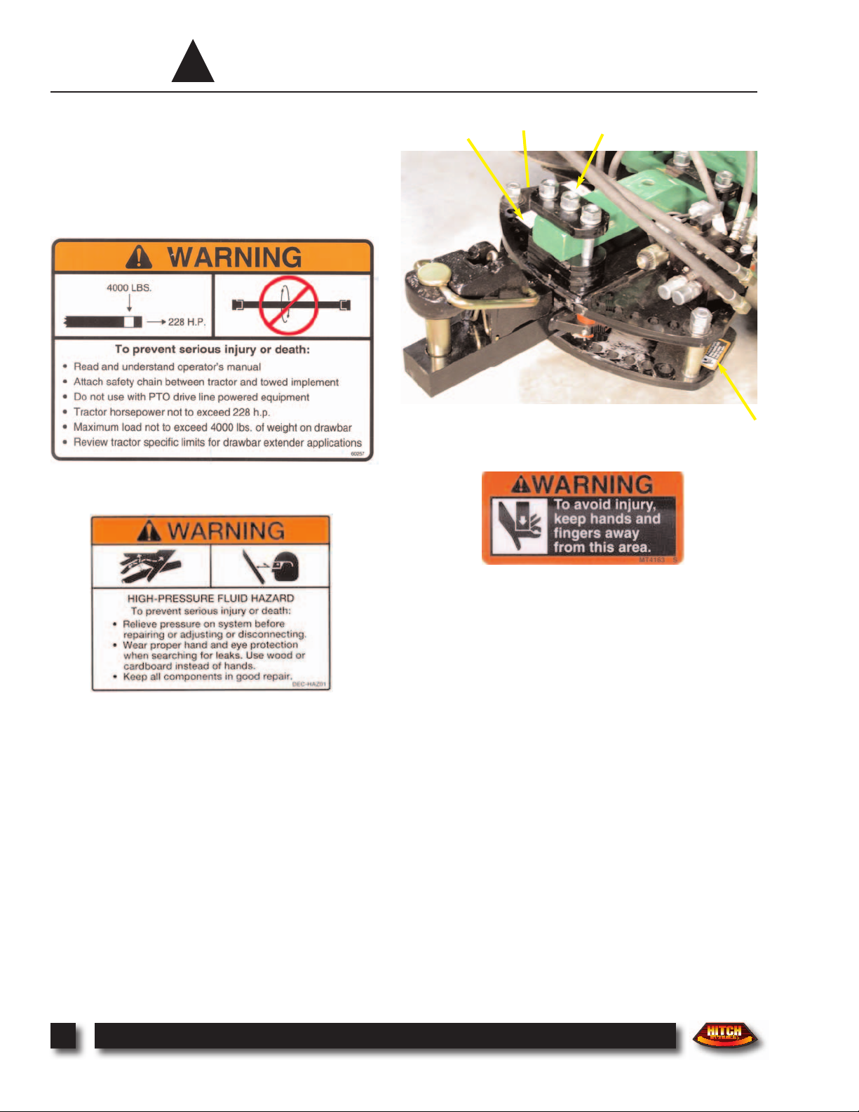
Safety Sign Locations and Care
!
A
C
B
C
P/N DEC-MT4163 C
P/N DEC-HAZ01 B
P/N 60257 A
Safety Sign Care:
•
Keep safety signs clean and legible at all times.
•
Replace safety signs that are missing or have become
illegible.
•
Replaced parts that displayed a safety sign should also
display the current sign.
•
Replacement safety signs are available from your
distributor, dealer, or online at outbackguidance.com
Installing Safety Signs:
•
Be sure that the installation area is clean and dry.
•
Decide on the exact position before you remove the
backing paper.
•
Remove the smallest portion of the split backing
paper.
•
Align the decal over the specified area, and carefully
press the small portion with the exposed sticky backing
in place.
•
Slowly peel back the remaining paper, and carefully
smooth the remaining portion of the decal in place.
•
Small air pockets can be pierced with a pin and
smoothed out using the piece of decal backing paper.
Page 7

G
P
S
I
M
P
L
E
M
E
N
T
G
U
I
D
A
N
C
E
®
5
Safety Information
!
As the manufacturer of your Outback Hitch Drawbar
Implement Guidance System, we care about your safety. In
fact, this machine and its systems have been designed to
provide maximum safety. Unfortunately, no machine
design can prevent operator error or carelessness.
This operator’s manual provides instructions for the
safe operation and maintenance of the OutbackHitch.
Please read and understand this manual before operating
the machine.
DO NOT Use with PTO Drive-line Powered Equipment. A tractormounted PTO drive shaft is not designed for use with a swinging drawbar
extender, such as the Outback
Hitch.
WARNING:
!
DO NOT Exceed Weight Limits. Review tractor specific limits for drawbar
extender application. The maximum vertical static load is 4000 lbs. (1800 kg).
WARNING:
!
HIGH-PRESSURE FLUID HAZARD. The Hitch utilizes hydraulic compo-
nents. Always relieve pressure on the system before repairing or adjusting. To
avoid hazard, wear proper hand and eye protection, and keep in good repair.
WARNING:
!
MOVING PARTS HAZARD. To avoid injury, keep hands and fingers
away from the swinging Hitch drawbar area.
WARNING:
!
ALWAYS Attach Safety Chain Between Tractor and Implement.
WARNING:
!
Page 8
G
P
S
I
M
P
L
E
M
E
N
T
G
U
I
D
A
N
C
E
®
6
INSTALLATION
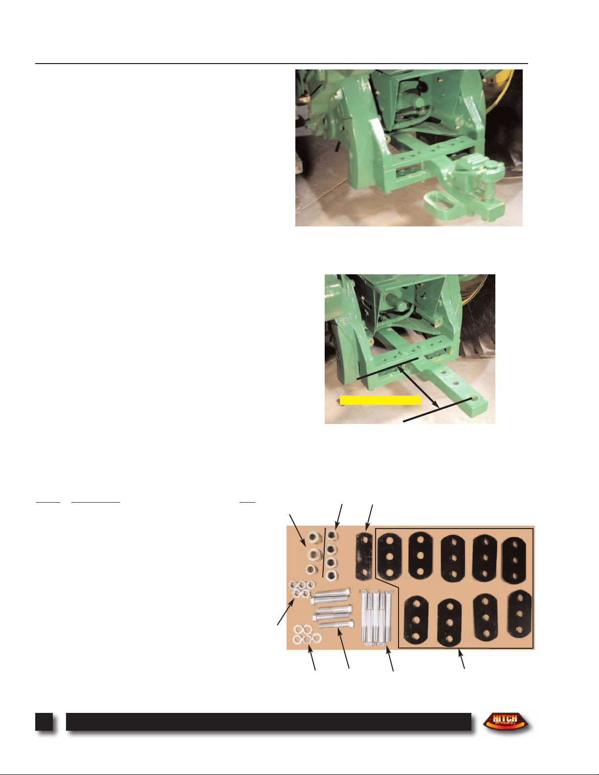
1. Tractor Preparation: Before attempting to install the
Outback® Hitch, park the tractor on a smooth level floor
with adequate clearance to work around the drawbar area.
Remove any accessories installed on the tractor drawbar
including the hammerstrap clevis and safety chain holder.
If the tractor is equipped with a drop-style drawbar, remove
the drawbar and flip it upside down. Reinstall the drawbar
as shown. The Outback® Hitch requires a minimum
mounting clearance of 14-1/4 in. (362mm) between the
center of the drawpin hole and the rear of the tractor support casting.
2. Determine Proper Mounting Configuration: The
Outback® Hitch is supplied with a universal mounting kit
(packaged in a burlap bag) and includes all necessary hardware to mount the hitch to most CAT II or III tractor drawbars. Not all parts included in the kit are required for each
specific installation.
Carefully review the mounting hardware details shown on
page A7 for your tractor specific mounting configuration.
Identify the required parts as shown.
Label
Description Qty
A 3/4” x 4” Hex Bolt, Gr5 5
B 3/4” x 6” Hex Bolt, Gr5 5
C 3/4” Lock Washer 5
D 3/4” Hex Nut, Gr5 5
E Hitch Hammer Strap Plate 1
F Hitch Spacer Plates:
3/4” Thick 3
1/2” Thick 4
1/4” Thick 2
G Draw Pin Bushings:
1-5/8”OD x 3/4”ID x 1-15/16”Lg 1
1-1/2”OD x 3/4”ID x 1-11/16”Lg 1
1-1/4”OD x 3/4”ID x 1-7/16”Lg 1
H CAT II Draw Bar Bushing:
1-3/8”OD x 13/16”ID x 1-7/16”Lg 4
14-1/4” (362mm) Min.
A
B
E
F
C
D
H
G
Page 9
G
P
S
I
M
P
L
E
M
E
N
T
G
U
I
D
A
N
C
E
®
7
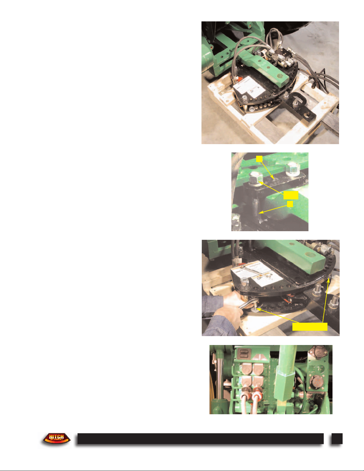
3. Mounting the Hitch: Using a forklift, floor jack, or
chain hoist, position the Outback® Hitch under the tractor
drawbar as shown. Notice that the hydraulic hoses to the
left cylinder must route over the top of the tractor drawbar.
Center the hitch directly under the tractor drawbar with the
drawpin hole lined up over the center of the corresponding
hitch mounting hole.
4. Install Hammerstrap at Front of Hitch: Insert
mounting bolt (A) into the front slot of the hitch, on both
sides of the drawbar, and install hammerstrap plate (E).
Secure with lock washers (C) and hex nuts (D). Do not
tighten hardware at this time. Slight adjustments of the
hitch forward or backward may be required to install
mounting hardware at the rear of the hitch.
5. Remove Hitch Shipping Pallet: The hitch is secured
to the shipping pallet with two lag screws and washers.
Remove both screws and lower the shipping pallet, allowing the hitch to be suspended from the front hammerstrap.
6. Connect Hydraulic Feed Hoses: The hitch hydraulic
supply lines have colored grips. Connect the supply lines
to the tractor remote outlets so that the red grip is pressure
and the black grip is return. During operation the hitch
requires a fixed 1.5 gpm oil flow, up to 3000 psi. Adjust
the tractor remote outlet oil flow to closely match this
requirement.
E
A
C D
REMOVE
Page 10
G
P
S
I
M
P
L
E
M
E
N
T
G
U
I
D
A
N
C
E
®
8
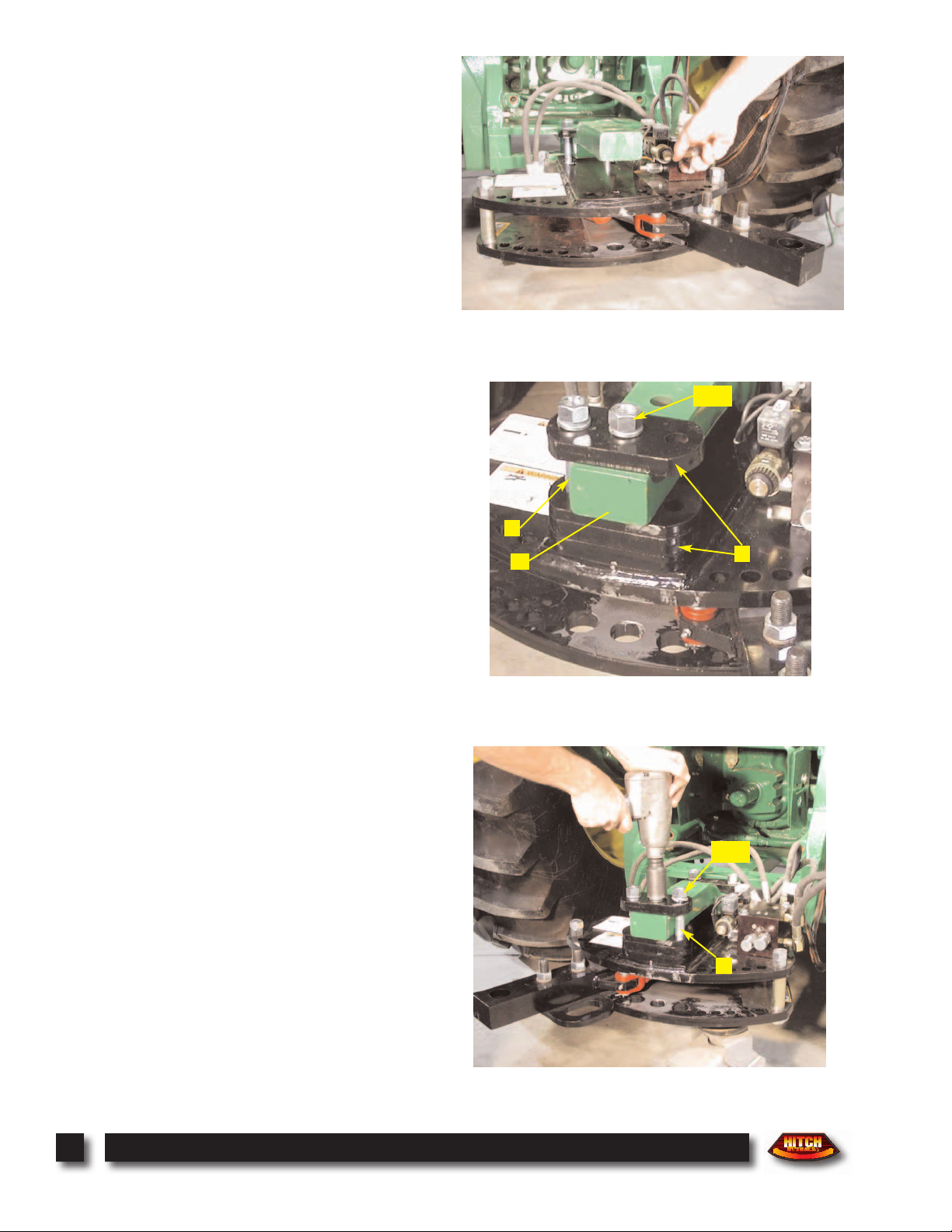
7. Move Hitch Drawbar Right: Start the tractor and
enable the hitch hydraulic remote outlet. The coils on the
hitch hydraulic control block have manual push button
overrides. Using a small screwdriver or common nail,
push the manual override at the center of the rear coil to
move the hitch drawbar to the far right extent. Disable the
hitch hydraulic remote outlet, and shut off the tractor.
8. Install Mounting Hardware at Rear of Hitch: Add
necessary hitch spacer plates (F) between the hitch and the
tractor drawbar so that the hitch is level. Insert the proper
sized draw pin bushing (G) into the tractor hitch pin hole.
Make certain that the bushing is not longer than the thickness of the tractor drawbar. Insert mounting bolts (B) up
from the bottom of the hitch through the top hitch plate,
spacer plates, and draw pin bushing. Install 3/4” thick
spacer plate (F) on top of the tractor drawbar, and secure
with lock washers (C) and hex nuts (D).
9. Move Hitch Drawbar Left: Start the tractor and
enable the hitch hydraulic remote outlet. Push the manual
override at the center of the front coil to move the hitch
drawbar to the far left extent. Disable the hitch hydraulic
remote outlet, and shut off the tractor.
10. Complete the Hitch Mounting: Insert the remaining
mounting bolt (B) up from the bottom of the hitch along
the right side of the tractor drawbar, and secure with lock
washer (C) and hex nut (D). Securely tighten all mounting
hardware (5 places), beginning with the rear center hex nut.
Make certain that the spacer plates tighten uniformly so
that no gaps are observed between the hitch and the tractor
drawbar.
B
C D
B
C D
F
G
Page 11

G
P
S
I
M
P
L
E
M
E
N
T
G
U
I
D
A
N
C
E
®
9
11. Determine Tilt Sensor Location: The tilt sensor
should be mounted directly onto the rear tractor frame in
an area protected from mud and flying debris. The sensor
must be oriented relative to the forward travel direction as
shown on the sensor decal. Orient the sensor with the label
up and the connector towards the rear. The sensor may
require re-orientation onto the sensor bracket to accommodate mounting directly to the tractor frame.
12. Mounting the Tilt Sensor: The preferred tilt sensor
mounting technique is to locate an extra bolt hole in the
rear tractor casting. The large slot on the sensor mounting
bracket can be slipped under the head of a mounting bolt
(customer supplied) and tightened. Make certain that the
sensor is oriented with the label up, level with the tractor,
and with the connector towards the rear.
13. Routing the Hitch Contol Cable: Route the hitch
control cable up from the drawbar past the tilt sensor and
through the back window of the tractor cab. Install the tilt
sensor cable connection. Secure the control cable with the
tie straps provided. Make certain that the control cable is
clear of any pinch points around the three-point linkage
and is protected from mud and flying debris.
Page 12

G
P
S
I
M
P
L
E
M
E
N
T
G
U
I
D
A
N
C
E
®
10
14. Exchange Power Cable: Install the Outback® S,
using the instruction booklet provided. Do not use the
power cable provided with it. Locate the Power/CAN
cable in the Hitch package. It has two connectors and a
cigarette lighter plug. Install the connector with two cables
coming out into the S Power/CAN port as shown. Twist
the connector firmly until it locks into place.
Note: The Outback® Hitch may also be used in combination with the optional Outback® 360. If a 360 is
already installed, step 14 is not required as the twoconnector Power/CAN cable is installed between the
S and the 360. Instead, a three-connector CAN
expansion cable is installed between the 360 and the
Hitch as described in step 15.
15. Daisy Chain Power Cable: Install the optional
Outback® 360, using the instruction booklet provided.
Locate the CAN expansion cable in the Hitch package. It
has three connectors in a ‘Y’ arrangement with a male and
female connector on one end and a female connector on the
other end. Disconnect the CAN connector from the 360
and insert the ‘Y’ end of the CAN expansion cable as
shown. Twist connectors firmly until they lock into place.
16. Rotate Suction Cup: Remove the Hitch console from
its package, and loosen the center adjusting bolt on the suction cup so the cup can be rotated 180 degrees. This puts
the pump button on top for easy access.
17. Mounting the Console: Find a desirable mounting
location inside the cab and THOROUGHLY clean the
glass. Remove the red cap from the vacuum mount, press
it to the window, and pump the button located on the vacuum mount. Pump until the red line is no longer visible on
the button. (Check it periodically. If the red line becomes
visible, you may have to pump it a little to maintain suction.) Adjust the display for proper viewing angle.
Note: Do not leave the console unattended for
extended periods of time. If possible, remove the unit
from glass when not in use. Continued exposure to
the elements (such as direct sunlight) can be harmful
to the suction cup.
With OBK-360, Insert Daisy Chain Power Cable Here
Page 13

G
P
S
I
M
P
L
E
M
E
N
T
G
U
I
D
A
N
C
E
®
11
18. Install CAN Cable: Install the remaining
Power/CAN connector (from either Step 14 or 15) into the
upper CAN port on the Hitch console as shown. Twist
connector firmly until it locks into place. For permanent
installations, we recommend removal of the cigarette
lighter plug and hard wiring the leads to a reliable 12-volt
power supply. The red wire goes to positive and the black
wire to negative.
Note: Cigarette lighter sockets are notorious for intermittent power. For maximum portability, install a
female cigarette lighter receptacle wired directly to the
battery for each application. For permanent installation, we recommend wiring directly to the battery.
19. Install Hitch Control Cable: Install the Hitch control
cable connector (from Step 13) into the lower HITCH port
on the Hitch console as shown. Twist the connector firmly
until it locks into place.
20. Install Auxiliary Power Cable: Locate the auxiliary
power cable in the Hitch package. It has a connector on
one end and a pair of ring terminals on the other. Install
the cable connector into the upper right PWR IN port on
the Hitch console as shown. Twist the connector firmly
until it locks into place. Route the auxiliary power cable
directly to the tractor battery. The red wire goes to positive, and the black wire goes to negative.
Page 14

G
P
S
I
M
P
L
E
M
E
N
T
G
U
I
D
A
N
C
E
®
12
GET ACQUAINTED WITH THE CONTROLS
RUN/HOLD
CENTER
LEFT/RIGHT ARROWS
MODE
S PRESENT
INDICATOR
HITCH POSITION
INDICATORS
HITCH POSITION INDICATORS: A series of 21 lights
indicate the current hitch pin position relative to the center
of the tractor. Each light represents approximately one
inch of hitch pin offset.
S PRESENT INDICATOR: This light indicates the presence of the Outback® S along with its GPS operational status. If the light is off, communication with the S cannot be
established. A blinking light indicates that the S cannot
establish DGPS. A solid green light must be present to
provide automatic hitch control.
MODE: Press the MODE button to change the current
hitch operating mode. Indicator lights show the current
mode as either Follow GPS, Match Tracks, or Manual.
LEFT/RIGHT ARROWS: Press the Left or Right Arrow
buttons to manually position the hitch pin position. The
arrow buttons are also used in Match Tracks mode to adjust
the amount of compensation necessary to match the implement tracks to the tractor. The light between the arrows
indicates when the left and right arrow buttons are active.
RUN/HOLD: Pressing these buttons enables or disables
the active hitch position control. The RUN button enables
the active hitch control in the selected mode, whereas the
HOLD button suspends active control of the hitch position.
Note: As a safety feature, the tractor must be traveling faster than one mile per hour before the RUN button can enable active hitch control.
CENTER: Press the CENTER Button to easily move the
hitch pin to center position and quickly prepare for road
travel. This CENTER feature may be initiated at any time
in all operating modes. A single press of the CENTER button automatically centers the hitch pin, puts the operating
mode in manual, and puts the status in hold.
Page 15

G
P
S
I
M
P
L
E
M
E
N
T
G
U
I
D
A
N
C
E
®
13
POWER UP
1. Power up both units: Turn on the power switches of
the S and Hitch in any order. The S will boot up and begin
acquiring a DPGS signal. The Hitch will establish communication with the S and wait for the DPGS signal to be
acquired.
2. Power up S only: Turn the power switch of the S on
and leave the Hitch off. This causes the S to operate as
normal. Refer to the Outback® S Manual for operation.
Outback®S Power Switch
Outback®Hitch Power Switch
SETUP
Configuration of the Outback® Hitch is accomplished
through the S, or 360, menu system. During power-up, the
Hitch is detected, and an additional menu option is included to configure the Hitch for operation.
To access the menu: Press the MENU button. Then
choose the HITCH CALIBRATE item. All functions in the
Outback® S console menu are navigated and selected
using the UP/DOWN ARROWS and the ENTER key.
1. POSITION: This function establishes the relation
between the actual hitch pin position and the measured
position as displayed on the Hitch console. Selecting this
function brings up three successive display screens to calibrate the left, right, and center hitch pin positions. Use the
LEFT/RIGHT ARROWS on the Hitch console to position
the physical hitch pin at the required location; then press
ENTER to update the calibration values.
2. CURVE: This function adjusts the amount of hitch pin
compensation necessary to match the implement tracks to
the tractor while driving around a curve. Drive the tractor
and implement to an open area which is relatively flat.
Proceed to drive around a large curve (typically 150 foot
radius or more). Observe how the implement is trailing
behind the tractor and use the LEFT/RIGHT ARROWS on
the Hitch console to adjust the hitch pin position so the
implement tracks match those of the tractor. Press ENTER
to update the curvature compensation value.
3. SLOPE: This function enables the Tilt Sensor for side
slope compensation and establishes a level reference value.
Selecting this function first displays an ON/OFF choice
selection. Selecting ON brings up a subsequent display
screen to adjust the level reference value. Park the tractor
on a nearly level surface. Press ENTER to update the level
reference value.
POSITION
Menu Item Display Sequence
Instructions
Press LEFT ARROW until hitch pin is at far left position.
Press ENTER to update left position.
Press RIGHT ARROW until hitch pin is at far right position.
Press ENTER to update right position.
Press LEFT ARROW until hitch pin is in the center.
Press ENTER to update center position.
ADJ LEFT ??
ENTER TO UPDATE
ADJ RIGHT ??
ENTER TO UPDATE
ADJ CENTER ??
ENTER TO UPDATE
CURVE
ADJ CURVE ??
ENTER TO UPDATE
Drive around a curve on relatively flat ground and observe trailing implement
tracking. Press LEFT or RIGHT ARROW until implement track matches those
of the tractor. Press ENTER to update curvature compensation value.
SLOPE
>ON
OFF
LEVEL GND ??
ENTER TO UPDATE
Select if Tilt Sensor is to be used for side slope compensation.
Park the tractor on a nearly level surface.
Press ENTER to update the level reference value.
SETUP : HITCH CALIBRATE MENU
Page 16

G
P
S
I
M
P
L
E
M
E
N
T
G
U
I
D
A
N
C
E
®
14
Follow GPS Mode: This mode causes the hitch to seek
the GPS guideline you are following. For example, if you
drive right of the
guideline, the hitch
will move left to compensate.
In follow GPS mode,
use the Outback® S as
normal. You can
establish a guideline
using either straight or
contour guidance.
Simply drive the tractor near the guideline,
and the Hitch will
position the hitch pin
directly over the line.
Note: When operating with the Hitch in follow GPS
mode, the Outback® S and 360 use the actual hitch
pin position for contour guidance logging and application mapping.
OPERATION
GPS Guideline
Hitch positions
implement on
GPS Guideline
Tractor off
to right of
GPS Guideline
Match Tracks Mode: This mode is for driving through
standing crop in side-hills and curves. For example, when
the tractor leans left on a sidehill, the hitch adjusts right so
the implement tires don’t damage the crop. The amount of
adjustment is proportional to
the measured tilt of the tractor.
The sensitivity of the slope
compensation may be adjusted
using the LEFT/RIGHT
ARROWS, as you drive
through the standing row crop.
Likewise, when following rows
around a curve to the right, the
hitch adjusts left to minimize
crop damage. The amount of
adjustment is proportional to
the sharpness of the turn. The
sensitivity of the curve compensation is adjusted in the HITCH
CALIBRATE setup menu.
Note: When operating with the Hitch in match tracks
mode, the Outback® S displays MATCH TRACKS
and does not provide driving guidance. The
Outback® 360 operates as normal and records the
GPS antenna position for application mapping.
Implement Matches Tracks
Downhill Slope
GPS Guideline
Implement Matches Tracks
The operation of the Outback® Hitch is quite simple.
Turn it on, activate the tractor hydraulics, select the desired
MODE, press RUN, and the rest is automatic.
Note: As a safety feature, the tractor must be traveling faster than one mile per hour before the RUN button can enable active hitch control.
Manual Mode: This mode allows the operator to position
the hitch pin at any desired offset using the LEFT/RIGHT
ARROWS. When operating with the Hitch in manual
mode, the Outback® S and 360 operate as normal. All
functions of the S and 360 are affected by the presence of
the hitch.
Page 17

G
P
S
I
M
P
L
E
M
E
N
T
G
U
I
D
A
N
C
E
®
15
MAINTENANCE
Proper maintenance of the Outback® Hitch mechanical
components will ensure years of dependable service and
protect your investment.
Initial Installation: After the first few hours of operation,
check the tightness of all Hitch mounting bolts and hardware. Substantial wear will occur to the Hitch and tractor
drawbar if mounting bolts are not properly tensioned.
Grease Fittings: Proper lubrication of the 5 grease locations at 12-hour intervals will dramatically prolong the life
of friction production parts. Use an SAE multi-purpose
type grease. Make sure to clean the fittings thoroughly
before using any grease gun.
Replace Worn Components: At the begining of each
application season, check the hitch drawbar for any signs
of free-play, both up and down and side to side. All wear
points of the Hitch include serviceable replacement parts.
Refer to pages A4 and A5 for details.
TROUBLE-SHOOTING TIPS
12 Hours
(3 Places)
12 Hours
(2 Places)
GREASE LOCATIONS
Problem - Probable Cause. Action
Hitch Drawbar Doesn’t Move
√ Tractor Hydraulics Not Active. Make sure hydraulic hoses are hooked up correctly (red hand grip to pressure;
black hand grip to return). Use push button over-rides on hydraulic block coils to verify operation.
√ Poor Electrical Connection. Check the indicator lights on the hydraulic block coil connectors. If no lights,
check cable connections. If lights show, then replace coil.
Hitch Drawbar Moves in the Wrong Direction
√ Tractor Hydraulics Reversed. Make sure hydraulic hoses are hooked up correctly (red hand grip to pressure;
black hand grip to return).
Page 18

CONTACTING THE
FACTORY
Outback Guidance®
Division of RHS, Inc.
2005 West Oregon Street, Box 394
Hiawatha, KS 66434
USA
All correspondence to the factory must be in English.
ONLINE:
http://www.outbackguidance.com
PHONE:
Monday Through Friday 8 A.M. - 5 P.M. U.S. Central Time
U.S:
1-800-247-3808 (Customer Service & Ordering)
Canada:
1-866-888-4472 (Customer Service & Ordering)
From all other countries:
01-785-742-2949
E-MAIL:
24 hours / 7 days a week
Your inquiry will receive a response from one of our
Customer Support Representatives within one business day.
Sales: outbacksales@outbackguidance.com
Customer Service: outbackcs@outbackguidance.com
Website Feedback: outbackweb@outbackguidance.com
FAX:
24 hours / 7 days a week
Your inquiry will receive a response from one of our
Customer Support Representatives within one business day.
1-785-742-4584
16
G
P
S
I
M
P
L
E
M
E
N
T
G
U
I
D
A
N
C
E
®
Page 19

Limited Outback® Hitch
One-Year Warranty
RHS, Inc. ("RHS") manufactures its hardware products
from parts and components that are in accordance with
industry standard practices. RHS warrants that the hardware products it manufactures will be free from defects in
materials and workmanship. The limited warranty term is
one year, beginning on the date of invoice to the original
purchaser.
Damage caused by shipping the product(s) to the original
purchaser is covered under this limited warranty.
Otherwise, this limited warranty does not cover damage
due to external causes, including accident, abuse, misuse,
problems with electrical power, servicing not authorized by
RHS, usage not in accordance with product instructions,
failure to perform required preventive maintenance and
problems caused by use of parts and components not supplied by RHS.
This limited warranty does not cover any items that are in
one or more of the following categories: software (RHS
authorized revision updates may be purchased), external
devices (except as specifically noted), accessories or parts
added to an Outback® Hitch system after the system is
shipped from RHS, accessories or parts that are not
installed in the RHS factory.
RHS will repair or replace product(s) covered under this
limited warranty that are returned to the RHS facility. To
request warranty service, you must call RHS (800-247-
3808) or go to outbackguidance.com for information, within the warranty period. If warranty service is required,
RHS will issue a Return Material Authorization Number.
You must ship the products back to RHS in their original or
equivalent packaging, prepay shipping charges, and insure
the shipment or accept risk of loss or damage during shipment. RHS will ship by UPS Ground Service the repaired
or replacement products, within 5 business days, freight
paid. In any instance in which RHS issues a Return
Material Authorization Number, RHS must receive the
product(s) for repair prior to the expiration of the warranty
period in order for the repair(s) to be covered by the limited
warranty.
RHS owns all parts removed from repaired products. RHS
uses new and reconditioned parts made by various manufacturers in performing warranty repairs and building
replacement products. If RHS repairs or replaces a product, its warranty term is the remainder of the limited warranty term.
RHS MAKES NO EXPRESS WARRANTIES OR CONDITIONS BEYOND THOSE STATED IN THIS LIMITED
WARRANTY STATEMENT. RHS DISCLAIMS ALL
OTHER WARRANTIES AND CONDITIONS, EXPRESS
OR IMPLIED, INCLUDING WITHOUT LIMITATION
IMPLIED WARRANTIES AND CONDITIONS OF MERCHANTABILITY AND FITNESS FOR A PARTICULAR
PURPOSE. SOME STATES (OR JURISDICTIONS) DO
NOT ALLOW LIMITATIONS ON IMPLIED WARRANTIES OR CONDITIONS, SO THIS LIMITATION
MAY NOT APPLY TO YOU.
RHS RESPONSIBILITY FOR MALFUNCTIONS AND
DEFECTS IN HARDWARE IS LIMITED TO REPAIR
AND REPLACEMENT AS SET FORTH IN THIS LIMITED WARRANTY STATEMENT. THESE WARRANTIES
GIVE YOU SPECIFIC LEGAL RIGHTS, AND YOU
MAY ALSO HAVE OTHER RIGHTS, WHICH VARY
FROM STATE TO STATE (OR JURISDICTION TO
JURISDICTION).
RHS DOES NOT ACCEPT LIABILITY BEYOND THE
REMEDIES SET FORTH IN THIS LIMITED WARRANTY STATEMENT OR LIABILITY FOR INCIDENTAL
OR CONSEQUENTIAL DAMAGES, INCLUDING
WITHOUT LIMITATION ANY LIABILITY FOR PRODUCTS NOT BEING AVAILABLE FOR USE OR FOR
LOST DATA OR SOFTWARE.
SOME STATES (OR JURISDICTIONS) DO NOT
ALLOW THE EXCLUSION OR LIMITATION OF INCIDENTAL OR CONSEQUENTIAL DAMAGES, SO THE
PRECEDING EXCLUSION OR LIMITATION MAY NOT
APPLY TO YOU.
These provisions apply to the RHS Limited Outback®
Hitch One-Year Warranty only. For provisions of any
extended service plan covering your system, refer to your
invoice or the separate extended service plan that you
received.
RHS reserves the right to make improvements in design or
changes in specifications at any time, without incurring any
obligation to owners of units previously sold.
No one is authorized to alter, modify, or enlarge this warranty nor the exclusions, limitations, and reservations.
G
P
S
I
M
P
L
E
M
E
N
T
G
U
I
D
A
N
C
E
®
17
Page 20

Limited Outback®
Hitch Three-Year
Extended Service Plan
The Outback® Hitch ESP only applies to the electronic
components of the product. Including the console, console
mounting, tilt sensor and related cables. The term “hardware” below applies only to the non-software portions of
the electronic components. Coverage for the mechanical
portions of Outback® Hitch are described in the one-year
warranty statement.
RHS,Inc. ("RHS") manufactures its hardware products
from parts and components that are in accordance with
industry standard practices. RHS warrants that the hardware products it manufactures will be free from defects in
materials and workmanship. The limited plan term is three
years, beginning on the date of invoice to the original purchaser.
Damage caused by shipping the product(s) to the original
purchaser is covered under this limited plan. Otherwise,
this limited plan does not cover damage due to external
causes, including accident, abuse, misuse, servicing not
authorized by RHS, usage not in accordance with product
instructions, failure to perform required preventive maintenance and problems caused by use of parts and components
not supplied by RHS.
This limited plan does not cover any items that are in one
or more of the following categories: software (except for
RHS authorized revision updates), external devices (except
as specifically noted), accessories or parts added to an
Outback® Hitch system after the system is shipped from
RHS, accessories or parts that are not installed in the RHS
factory.
RHS will provide, on an exchange basis and subject to the
RHS Exchange Policy in effect on the date of the exchange,
replacement parts (up to and including a complete
Outback® Hitch system) for the Outback® Hitch
product(s) covered under this limited plan when parts
require replacement. To request service, you must call
RHS (800-247-3808) or go to outbackguidance.com for
information within the plan period. If replacement is
required, RHS will issue a Return Material Authorization
Number and will ship by UPS Next Day Air & Saturday
Delivery the replacement parts within 1 business day. You
must ship by UPS Ground Service collect the original product(s) back to RHS in this packaging. In any instance in
which RHS issues a Return Material Authorization
Number, RHS must receive the original part(s) prior to the
expiration of the plan period in order for the replacement(s)
to be covered by the limited plan. Failure to return original
part(s) for which replacement(s) have been sent within 30
days of initial shipment will result in the issuance of an
invoice for the cost of the sent parts. RHS uses new and
reconditioned parts made by various manufacturers in performing warranty repairs and building replacement products. If RHS repairs or replaces a product, its plan term is
the remainder of the limited plan term.
RHS MAKES NO EXPRESS WARRANTIES OR CONDITIONS BEYOND THOSE STATED IN THIS LIMITED
WARRANTY STATEMENT. RHS DISCLAIMS ALL
OTHER WARRANTIES AND CONDITIONS, EXPRESS
OR IMPLIED, INCLUDING WITHOUT LIMITATION
IMPLIED WARRANTIES AND CONDITIONS OF MERCHANTABILITY AND FITNESS FOR A PARTICULAR
PURPOSE. SOME STATES (OR JURISDICTIONS) DO
NOT ALLOW LIMITATIONS ON IMPLIED WARRANTIES OR CONDITIONS, SO THIS LIMITATION
MAY NOT APPLY TO YOU.
RHS RESPONSIBILITY FOR MALFUNCTIONS AND
DEFECTS IN HARDWARE IS LIMITED TO REPAIR
AND REPLACEMENT AS SET FORTH IN THIS LIMITED WARRANTY STATEMENT. THESE WARRANTIES
GIVE YOU SPECIFIC LEGAL RIGHTS, AND YOU
MAY ALSO HAVE OTHER RIGHTS, WHICH VARY
FROM STATE TO STATE (OR JURISDICTION TO
JURISDICTION).
RHS DOES NOT ACCEPT LIABILITY BEYOND THE
REMEDIES SET FORTH IN THIS LIMITED WARRANTY STATEMENT OR LIABILITY FOR INCIDENTAL
OR CONSEQUENTIAL DAMAGES, INCLUDING
WITHOUT LIMITATION ANY LIABILITY FOR PRODUCTS NOT BEING AVAILABLE FOR USE OR FOR
LOST DATA OR SOFTWARE.
SOME STATES (OR JURISDICTIONS) DO NOT
ALLOW THE EXCLUSION OR LIMITATION OF INCIDENTAL OR CONSEQUENTIAL DAMAGES, SO THE
PRECEDING EXCLUSION OR LIMITATION MAY NOT
APPLY TO YOU.
These provisions apply to the RHS Limited Outback®
Hitch Three-Year Extended Service Plan only.
RHS reserves the right to make improvements in design or
changes in specifications at any time, without incurring any
obligation to owners of units previously sold.
No one is authorized to alter, modify, or enlarge this warranty nor the exclusions, limitations, and reservations.
G
P
S
I
M
P
L
E
M
E
N
T
G
U
I
D
A
N
C
E
®
18
G
P
S
I
M
P
L
E
M
E
N
T
G
U
I
D
A
N
C
E
®
Page 21

G
P
S
I
M
P
L
E
M
E
N
T
G
U
I
D
A
N
C
E
®
A1
Outback-Hitch Drawbar Guidance System
REF. P/N DESCRIPTION QTY.
1 OBK-S Outback-S Guidance System
2 OBK-360 Outback-360 Mapping System
3 60081 CAN/Power Cable, OBK-360/Hitch - 10ft Lg/15ft Lg, CLA 1
4 60099 Cable, CAN Expansion - 5' 1
5 60098 Cable, Auxiliary Power - 12' 1
6 Console Mounting Details, see page A2
7 AB674 Cable, Hitch Interface - OBK Hitch 1
8 TS-7R Tie Strap, 7" - Releasable 6
9 Tilt Sensor Mounting Details, see page A2
10 Mounting Hardware Details, see page A7
11 Hydraulic & Electrical Assy, see page A3
12 Mechanical Assy, see page A4
DOM-OBK03 Owner's Manual, OBK-Hitch 1
PARTS LISTING
Page 22

G
P
S
I
M
P
L
E
M
E
N
T
G
U
I
D
A
N
C
E
®
A2
Tilt Sensor Mounting Details
REF. P/N DESCRIPTION QTY.
1 AB673 Tilt Sensor - OBK Hitch 1
2 AB677 Bracket, Tilt Sensor Mount - OBK Hitch 1
3 B#8.12 Bolt, #8 x 1/2 Phil Rnd Hd, ZP 2
4 LN#8K Nut, Keeper Lock - #8-32 2
Console Mounting Details
REF. P/N DESCRIPTION QTY.
1 60066 Vacuum Cup, 4-1/2" /w 1/4NC Insert 1
2 60063 Washer, Rubber - 2-1/4OD x 3/8ID x 1/8T 1
3 AB440 Base, Console Mounting - OBK-S/360 1
4 60065 Knob, 3-Arm - 1/4NC x 1/2 Stud, 1-1/8 Dia. 3
5 60064 Washer, Rubber - 1-1/2OD x 3/4ID x 3/32T 2
6 AB441 Frame, Console Mounting - OBK-S 1
7 60097 Outback Hitch Console 1
8 60068 Knob, Thumbscrew - #8-32 x 1/4" Stud 2
Page 23

G
P
S
I
M
P
L
E
M
E
N
T
G
U
I
D
A
N
C
E
®
A3
Hydraulic & Electrical Assembly
REF. P/N DESCRIPTION QTY.
1 Mechanical Assy, see page A4
2 60229 Hydraulic Valve Assy, see page A6 1
3 FW38N Washer, Narrow Flat - 3/4"OD x 13/32ID x 1/16"thk, ZP 2
4 B38.4 Bolt, 3/8NC x 4 Gr5 ZP 2
5 60233 Hose, Hyd. - 1/4"x24"lg, #4 Female JIC x #4 Male JIC 2
6 60232 Hose, Hyd. - 1/4"x18"lg, #4 Female JIC x #4 Male JIC 2
7 60231 Hose, Hyd. - 3/8"x60"lg, #6 Male ORB 90deg x 1/2" MPT 2
8 69266 Hydra Grip - One Pair, Red and Black 1
9 8FP-QM Adapter, Hyd. Quick Disconnect - Male Tip x 1/2"fpt 2
10 AB674 Cable, Hitch Interface 1
11 WA027 Clamp, Cushioned Cable - 1/2"DIA. x 1/2"WIDE 1
12 B14.34 Bolt, 1/4NC x 3/4 Gr5 ZP 1
13 60257 Decal, Hazard - Outback Hitch General Warning 1
14 DEC-HAZ01 Decal, Warning - High Pressure Fluid 1
15 DEC-MT4163 Decal, Warning - Pinch Point 2
Page 24

G
P
S
I
M
P
L
E
M
E
N
T
G
U
I
D
A
N
C
E
®
A4
Mechanical Assembly
REF. P/N DESCRIPTION QTY.
1 AB663 Wment, Hitch Bottom 1
2 60214 Pin, Hitch Main 1
3 B12.212 Bolt, 1/2NC x 2-1/2 Gr5 ZP 1
4 LN12 Nut, Lock - 1/2NC ZP 1
5 B34.6 Bolt, 3/4NC x 6 Gr5 ZP 4
6 60220 Washer, Shim - 1-1/8"OD x 3/4"ID x 0.062"TH 8
7 60217 Washer, Shim - 1-5/8"OD x 1-1/8"ID x 0.047"TH 2
8 60216 Bushing, Hitch Spacer 4
9 Drawbar Sub-Assembly, see page A5
10 60218 Left Cylinder Assy, see page A6 1
11 60219 Right Cylinder Assy /w Sensor, see page A6 1
12 CLP34.2 Pin, Clevis - 3/4" x 2" ZP 2
13 60220 Washer, Shim - 1-1/8"OD x 3/4"ID x 0.062"TH 4
14 CP532.114 Pin, Cotter - 5/32" x 1-1/4", ZP 2
15 AB664 Wment, Hitch Top 1
16 N34 Nut, 3/4NC Gr5 ZP 8
Page 25

G
P
S
I
M
P
L
E
M
E
N
T
G
U
I
D
A
N
C
E
®
A5
Drawbar Sub-Assembly
REF. P/N DESCRIPTION QTY.
1 AB665 Wment, Hitch Drawbar 1
2 LSI-2022-20 Sleeve, L280 - 1.25"ID x 1.375"OD x 1.25"Lg 2
3 60245 Bearing, Composite Sleeve - 3/4"ID x 7/8"OD x 3/4"Lg 2
4 69573 Zerk, Grease 1/4-28 Threaded 3
5 AB667 Wear Plate, Hitch Drawbar 2
6 B56.1FSC Bolt, Hex Socket Flat Head - 5/16NC x 1", ZP 6
7 AB676 Flat, Safety Chain Support 1
8 BM20.110 Bolt, Hex - 20m2.5 x 110, YZ 2
9 LWM20 Washer, Lock - M20, YZ 2
10 NM20 Nut, Hex - 20m2.5, YZ 2
11 60205 Key, 1/2”SQ. x 1-1/2” - 1018, ZP, undersized 4
Page 26

G
P
S
I
M
P
L
E
M
E
N
T
G
U
I
D
A
N
C
E
®
A6
Hydraulic Component Details
REF. P/N DESCRIPTION QTY.
1 60239 Replacement Seal Kit /w Instructions 2
2 60240 Replacement Sensor Kit /w Instructions 1
3 4MB-4MJ90 Adapter, Hyd. - #4 Male ORB x #4 Male JIC, 90deg 4
4 60241 Assy, Hydraulic Tube 2
5 69573 Zerk, Grease 1/4-28 Threaded 2
6 60234 Coil, Directional Valve - D02, 12VDC, DIN 2
7 60235 Valve, Directional /w Coils - DO2 Closed Center, Standard 1
60236 Valve, Directional /w Coils - DO2 Tandem Center, Alternate
8 60237 Cartridge, Pressure Comp. - 1.5 GPM Fixed 1
9 60238 Cartridge, Counter Balance - Set 3000 PSI Crack 2
10 4MB-4FJ90 Adpater, Hyd. - #4 Male ORB x #4 Female JIC, 90deg 2
11 4MB-4MJ90 Adapter, Hyd. - #4 Male ORB x #4 Male JIC, 90deg 2
Page 27

G
P
S
I
M
P
L
E
M
E
N
T
G
U
I
D
A
N
C
E
®
A7
Mounting Hardware Details
REF. P/N DESCRIPTION QTY.
1 B34.4 Bolt, 3/4NC x 4 Gr5 ZP 5
2 B34.6 Bolt, 3/4NC x 6 Gr5 ZP 5
3 N34 Nut, 3/4NC Gr5 ZP 5
4 LW34 Washer, Lock - 3/4" ZP 5
5 AB672 Flat, Hitch Mount Hammer Strap 1
6A AB671 Flat, Hitch Mount Spacer - 3/4" 3
6B AB669 Flat, Hitch Mount Spacer - 1/2" 4
6C AB670 Flat, Hitch Mount Spacer - 1/4" 2
7A 60223 Bushing, Hitch Draw Pin - 1-5/8"OD x 3/4"ID x 1-15/16"Lg 1
7B 60222 Bushing, Hitch Draw Pin - 1-1/2"OD x 3/4"ID x 1-11/16"Lg 1
7C 60224 Bushing, Hitch Draw Pin - 1-1/4"OD x 3/4"ID x 1-7/16"Lg 1
8 60221 Bushing, Hitch Cat II Mount Spacer 4
Page 28

G
P
S
I
M
P
L
E
M
E
N
T
G
U
I
D
A
N
C
E
®
A8
Clevis Hitch Attachment [Optional]
REF. P/N DESCRIPTION QTY.
1 60246 Hammerstrap, Cat. 3 Drawbar 1
2 60248 Hitch Pin Trigger, Cat 3 Drawbar 1
3 60247 Hitch Pin, Cat 3 Drawbar 1
*4 BM20.110 Bolt, Hex - 20m2.5 x 110, YZ 2
*5 LWM20 Washer, Lock - M20, YZ 2
*6 AB676 Flat, Safety Chain Support 1
DIP-OB014 Installation Instructions, Clevis Hitch Attachment 1
*Items 4, 5, & 6 supplied with drawbar hitch assembly.
Page 29

G
P
S
I
M
P
L
E
M
E
N
T
G
U
I
D
A
N
C
E
®
A9
Page 30

G
P
S
I
M
P
L
E
M
E
N
T
G
U
I
D
A
N
C
E
®
A10
Page 31

Page 32

 Loading...