

Page 1
OUTBACK S
OWNER’S MANUAL
TM
December, 2005 DOM-OBK01 Rev. D
Page 2
Introduction . . . . . . . . . . . . . . . . . . . . . . . . . . . . . . . .1
Installation . . . . . . . . . . . . . . . . . . . . . . . . . . . . . . . . .2
Power Up . . . . . . . . . . . . . . . . . . . . . . . . . . . . . . . . . .5
Setup . . . . . . . . . . . . . . . . . . . . . . . . . . . . . . . . . . . . .5
Correction Types . . . . . . . . . . . . . . . . . . . . . . . . . . . .6
Contour Guidance . . . . . . . . . . . . . . . . . . . . . . . . . . .7
Straight Guidance . . . . . . . . . . . . . . . . . . . . . . . . . . .8
Headland Presence . . . . . . . . . . . . . . . . . . . . . . . . . .9
Alternate Display Screens . . . . . . . . . . . . . . . . . . . . .9
On-The-Go A=B Line Adjust . . . . . . . . . . . . . . . . .10
Congratulations on your purchase of an Outback S
GPS Guidance unit. We at Hemisphere GPS wish to
thank you for your patronage and appreciate your con-
TM
fidence in OUTBACK
TM
S
GPS Guidance unit has been carefully designed
equipment. Your Outback
and ruggedly built to provide many years of depend-
able service in return for your investment.
TM
Field Perimeter Area . . . . . . . . . . . . . . . . . . . . . . . .10
Stop Guidance . . . . . . . . . . . . . . . . . . . . . . . . . . . . .12
Using e-Dif
Outback S
Changing Default Settings . . . . . . . . . . . . . . . . . . .14
Diagnostics . . . . . . . . . . . . . . . . . . . . . . . . . . . . . . .15
Troubleshooting . . . . . . . . . . . . . . . . . . . . . . . . . . . .16
Frequently Asked Questions . . . . . . . . . . . . . . . . . .19
TM
. . . . . . . . . . . . . . . . . . . . . . . . . . . . . .13
TM
Communications . . . . . . . . . . . . . . . . .14
This manual has been prepared to assist you in the
TM
operation and maintenance of your Outback S
GPS
Guidance unit and to provide the necessary part num-
bers to keep it in near original condition.
Contacting the Factory . . . . . . . . . . . . . . . . . . . . . .23
Outback Warranties . . . . . . . . . . . . . . . . . . . . . . . . .24
Parts Listing . . . . . . . . . . . . . . . . . . . . . . . . . . . . . .29
Footnotes: OUTBACK™, OUTBACK Guidance®, OUTBACK Guidance Center™, OUTBACK S™, OUTBACK S2™, OUTBACK 360™. OUTBACK Steering
Guide™, OUTBACK Hitch™, eDrive®, Just Let Go™ and Baseline™ are proprietary trademarks of Hemisphere GPS, L.L.C. The OUTBACK S™ automated navigation and steering guide system is protected under U.S. Patents No. 6,539,303 and No. 6,711,501. The OUTBACK Hitch™ automated hitch control system is protected
under U.S. Patent No. 6,631,916. Other U.S. and international patents pending.
Outback S
TM
Serial Number______________________
INSTALLATION
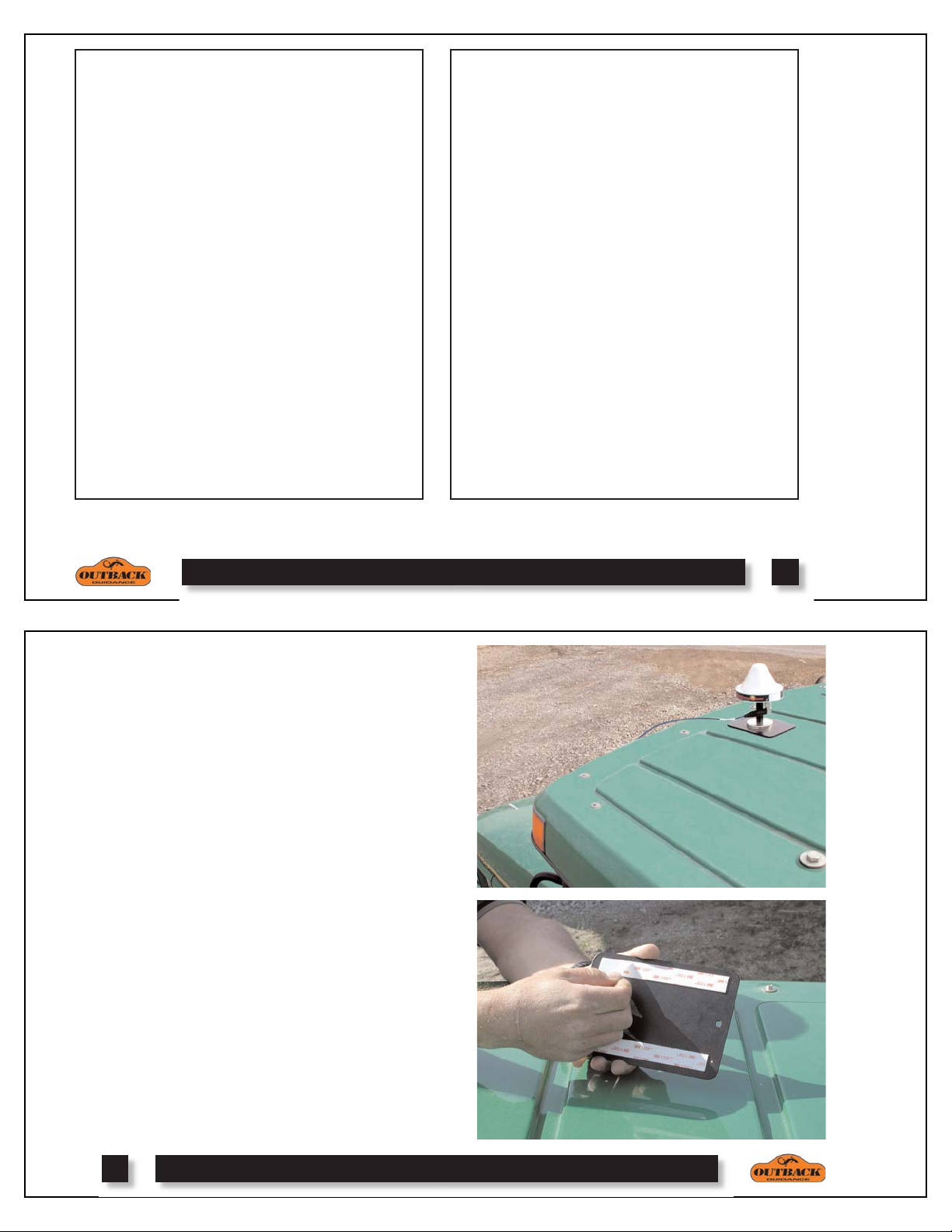
1. Determine Antenna Location: The antenna should
be mounted centered on the vehicle as high and as far
forward as possible. This is usually along the front edge
of the vehicle cab.
NOTE:
mitting radio antenna, for example: 2-way or business
band radio.
2. Attach Antenna: Clean and dry the surface where the
antenna mounting plate will be attached. Remove the
paper backing from the adhesive strips on the back of the
mounting plate. Position the mounting plate and press
down hard for good adhesion. Place the magnetic mounted antenna on the plate and be sure it is on the exact centerline of the vehicle.
Do not place the antenna within 2 feet of a trans-
1
2
Page 3
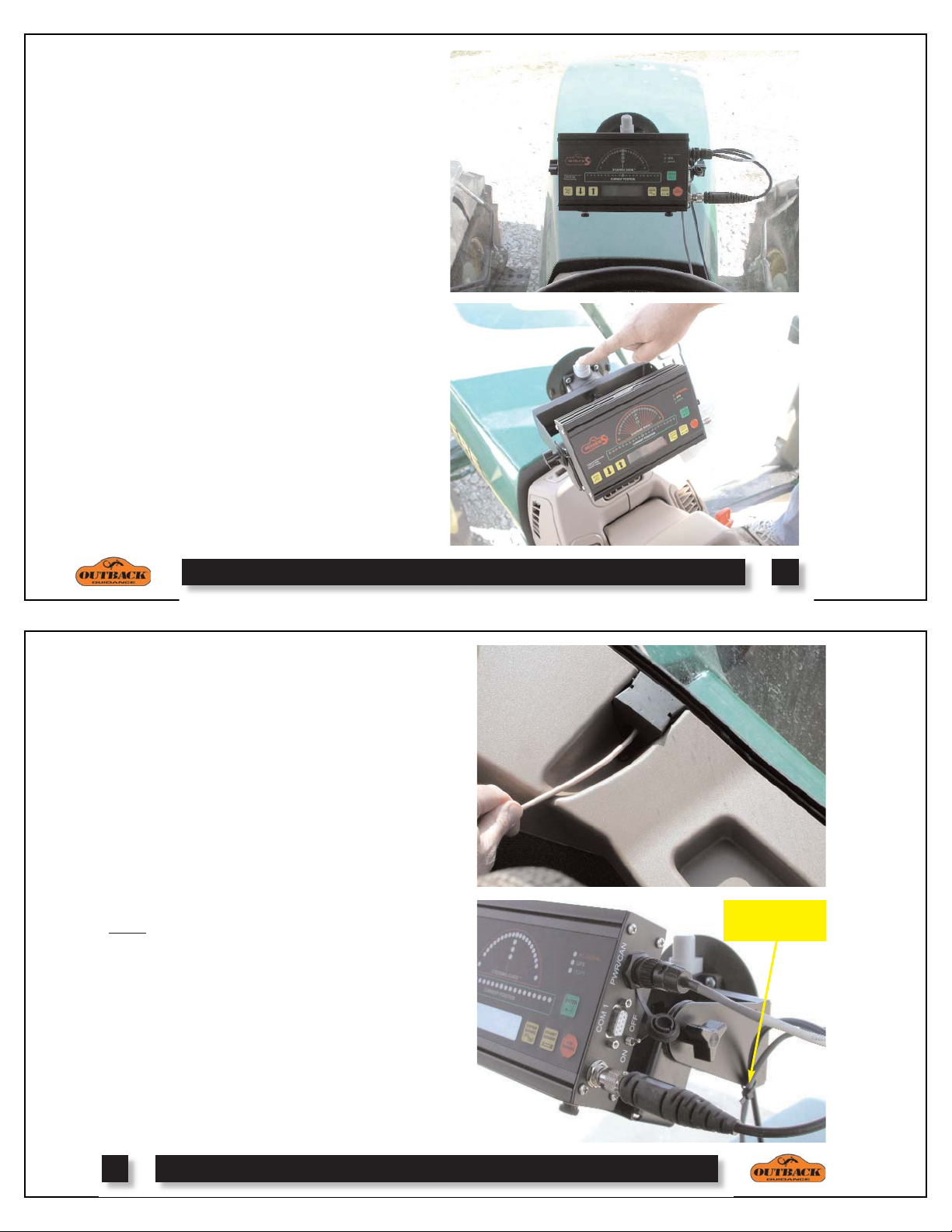
3. Determine Display Location: Normally, the display is located above and behind the center of the
steering wheel just below the driver's line of sight.
The easiest installation is on the front glass of the cab.
If that's not possible, it can vacuum mount to any non
porous (metal) surface or the vacuum mount can be
removed and the bracket mounted with bolts.
4. Mount Display Unit: THOROUGHLY clean the
inside cab window surface directly in front of the
steering wheel. Remove the red cover of the vacuum
mount, press it to the window and pump the button
located on the vacuum mount. Pump until the red line
is no longer visible on the button. (Check it periodically. If the red line becomes visible, you may have to
pump it a little to maintain suction). Adjust the display
for proper viewing angle.
NOTE: Do not leave console unattended for
extended periods of time. If possible, remove the
unit from glass when not in use. Continued exposure to the elements (such as direct sunlight), can
be harmful to the suction cup.
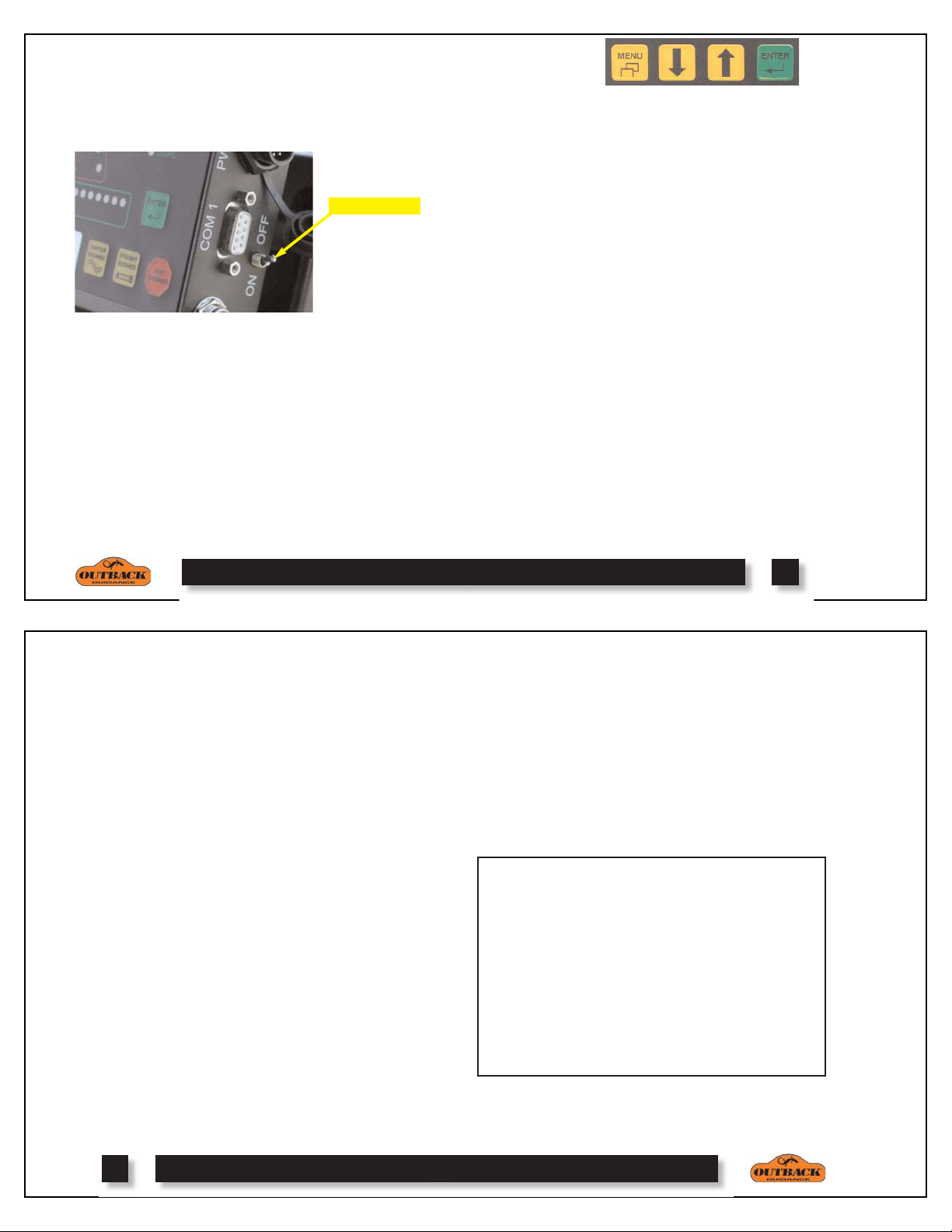
5. Route Antenna Cable: Securely attach one end of
the cable to the antenna. Route the cable to a cab
opening where rubber protection exists to protect the
cable. (A closed window works fine.) Do not bend
the cable to a radius of less than 6 inches. Avoid routing it within 12 inches of radio wires, power generator
wires, heat source or moving parts. Attach the other
end of the cable to the display unit. Coil excess cable
in a protected location and secure the installation with
tie straps.
6. Install Power Cable: Connect the power cable to
the display unit at the CAN port. Twist connector
firmly
until it snaps into place. For permanent installations, we recommend removal of the cigarette lighter
plug and hard-wiring the leads to a reliable 12 volt
power supply. Use a 5-amp inline fuse on the red lead
to protect the console and wiring. Red goes to positive
and black to negative. Coil excess cable in a protected
location and secure the installation with tie straps.
3
Use tie strap through
mounting hole to
relieve cable strain.
NOTE:
intermittent power. For permanent installation, we recommend wiring directly to the battery, using a 5-amp
inline fuse.
Cigarette lighter sockets are notorious for
4
Page 4
POWER UP
SETUP
1. Turn Unit On, After Starting Engine: Toggle the
power switch located on the right end of the display.
The RED status light will illuminate.
Power Switch
2. Acquire a DGPS Signal: The unit automatically
begins acquiring a DGPS signal. This process may take
a few minutes. During this process, the vehicle can be
moving or the operator can perform menu functions.
Upon achieving a GPS signal, the YELLOW status light
will illuminate. Finally, once the DGPS correction signal
is acquired, a GREEN status light will illuminate. The
GREEN DGPS light must be present for the Outback S
TM
to provide guidance.
NOTE:
to acquire a DGPS signal.
The antenna must have a clear view of the sky
Using the Menu: To access the menu, press the MENU
button. Choose the item you want using the up and
down arrow keys. The
> character points to the active
menu item. Press ENTER to select.
1. EDRIVE SETUP: Optional menu item appears only if
eDrive® is installed. See the Outback eDrive® owner’s manual for details.
2. BRIGHTNESS: Adjust the display brightness from 1 to 10
as desired. A setting of 1 is dim while a setting of 10 is bright.
3. UNITS OF MEASURE: Choose desired units of measure
as feet or meters.
4. SWATH WIDTH: Adjust this number to equal the width of
the implement or boom.
5. SENSITIVITY: Adjust guide sensitivity to LOW, MEDIUM or HIGH.
6. SHIFT A=B: Adjust straight guidance A=B line left or right
(see page 9).
7. HEADLAND ALERT: Turn headland indicator on or off.
8. PERIMETER SETUP: Select RIGHT, CENTER, or LEFT
edge of swath width for field perimeter area calculation (see
page 10).
9. DIAGNOSTICS: (See page 15)
10. CORRECTION TYPE: (See Page 6)
11. NMEA PORT SETUP: (See Page 14)
12. LANGUAGE: Select desired language choice.
CORRECTION TYPES
The differential correction type used by the Outback S
is selected from the two options loaded into the receiver.
WAAS and e-Dif
TM
are the factory installed options with
other types available as field installed options. The correction type can be changed from the CORRECTION
TYPE item in the setup menu (see page 5). Choose
WAAS, e-Dif
TM
, EGNOS, OmniStar, or other field
installed correction option(s).
WAAS is free and is available anywhere in North
TM
America. e-Dif
, as factory installed, is pre-activated
with a secondary one-time subscription code which can
be used only in North America. A one-time primary sub-
TM
scription to e-Dif
may be purchased for use anywhere
in the world.
EGNOS, like WAAS, is also free and is available in
Europe. OmniStar correction service is available
throughout the world, however, an annual subscription
must be purchased. Field installation of OmniStar correction must replace one of the existing correction types
and may be performed either from a PC or from an
TM
Outback 360
.
TM
5
NOTE: The use of e-Dif™ on OUTBACK Guidance®
equipment as a GPS differential correction is intended
only for relative guidance applications and is not recommended for data recording and subsequent comparative
analysis. Relative positional accuracy will typically drift at
a rate of 1-2 meters (3-6.5 feet) per hour; however,
absolute positional accuracy errors may approach ±10
meters (±33 feet).
OmniStar Contacts
Houston, Texas USA
1-888-666-4782
For North, Central, and South America
West Perth, Australia
+61-89-322-5295
For South Africa, Far East and Australia/NZ
Leidschendam, Holland
+31-70-317-0900
For Europe, North Africa and Middle East
6
Page 5
CONTOUR GUIDANCE
1. Background: Choose contour guidance whenever
you want to follow previous passes. In this mode, you
are either logging an initial pass or guiding from a previous pass. After choosing contour guidance, you proceed by making your initial pass anywhere you like
without using the guide. Later, when you attempt to
follow a previous pass, the guide will turn on. Contour
guidance is generally used for working out borders,
turn areas and contour following.
2. Make The Initial Pass: Press CONTOUR GUIDANCE before beginning. The display will read “LOGGING PASS”. Proceed with the initial pass using any
path you desire.
4. Making A New First Pass: Let's say you've made
several passes and then want to start a new line that
doesn't follow the last one. Simply drive where you
want to go. Once it becomes obvious that you're not
guiding from another pass, the unit will go back into
logging pass mode.
5. Switching Modes: You may switch between
straight and contour at any time. When switching from
straight to contour, the Outback S
TM
guides from any
previously made pass.
3. Guide On Subsequent Passes: Anytime you
approach a previously made pass, the Outback S
TM
will
automatically recognize what you're doing and will
begin to guide. That pass, in turn, will become the pattern for the next pass and so forth. In contour mode,
any previous pass (even those made in straight mode)
can be used to guide from.
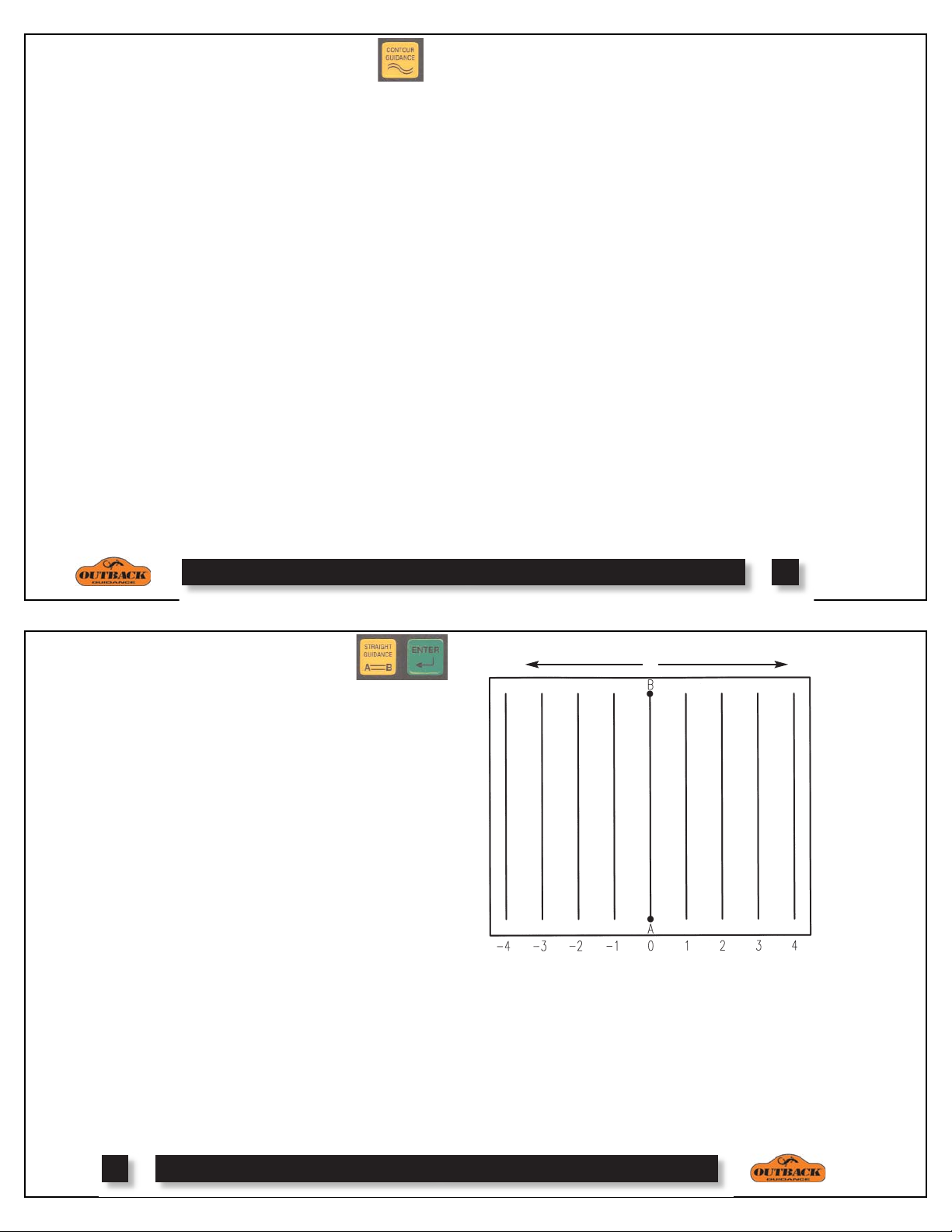
STRAIGHT GUIDANCE
Background: Choose straight guidance whenever you
want the unit to generate straight, parallel paths for you
to follow. You can establish the first pass along a
straight side of the field or you can divide the field
with a straight swath and work out each side. All passes will be perfectly and uniformly spaced across the
field.
7
Shift A=B Left
Shift A=B Right
An A=B line is defined by marking an A point and a B
point. The imaginary line that passes through those
two points defines the first pass. All other passes are
perfectly spaced on both sides of the first pass.
1. Mark Point A: With the tractor positioned at the
beginning of the first pass, press STRAIGHT GUIDANCE. You’ll get the message PRESS ENTER FOR
POINT “A”. Press ENTER to mark the point.
2. Mark Point B: Then drive some or all of the first
pass. If following a straight side of the field, go all the
way to the end before marking Point B. If dividing the
field, it's only necessary to go a short distance. You
will be prompted to press the ENTER button again to
mark Point B.
Pass Number
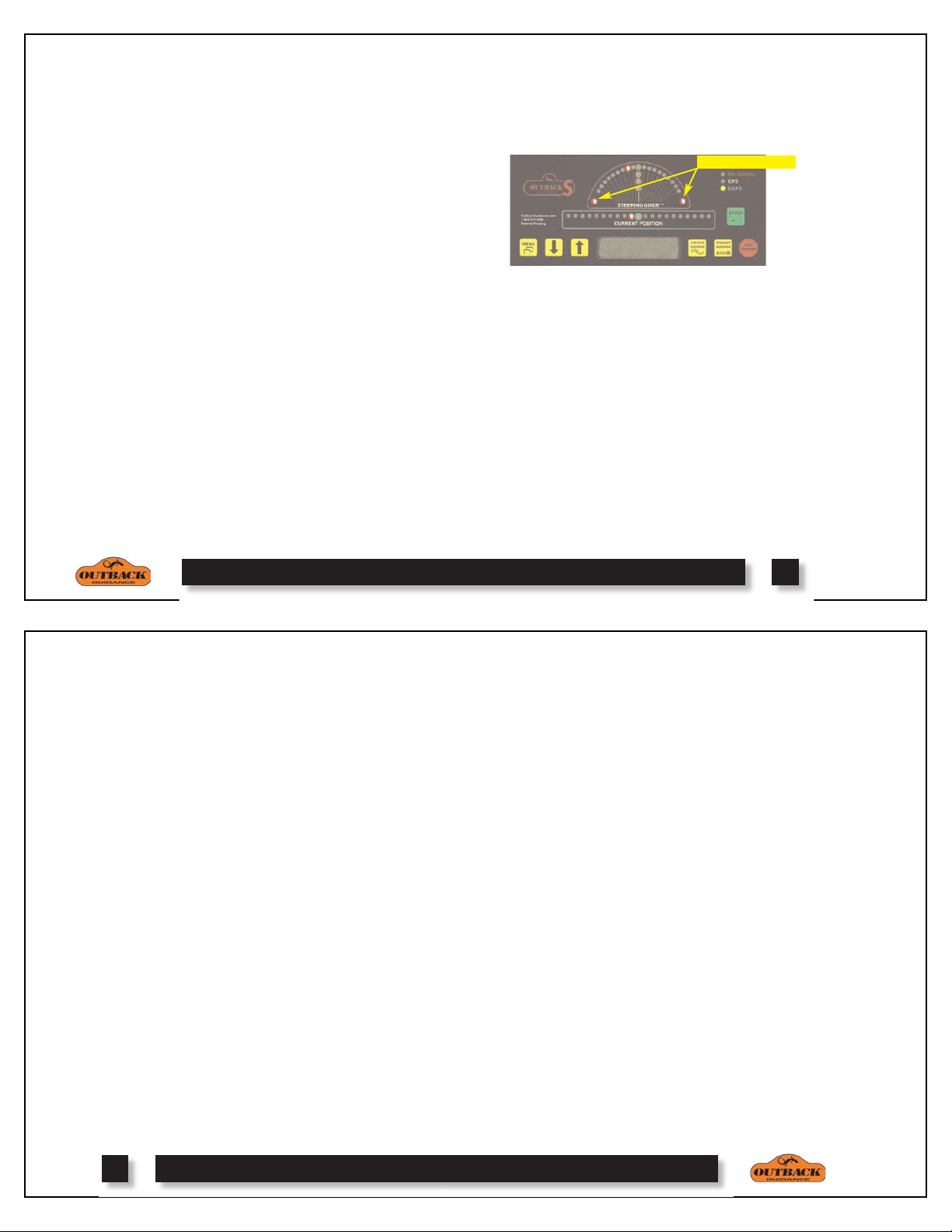
3. Begin Straight Guiding: After Point B is entered,
the unit automatically begins guiding. Keep the
Steering Guide™ lights centered by moving the steering wheel. When one pass is finished, just turn around
in the approximate area of the pass you wish to follow
and the unit will automatically seek the new pass.
8
Page 6
4. Switching Modes: You may switch between
straight and contour modes at will. When switching to
straight mode for the second time, you are given the
option of using the previous A=B line or setting a new
one.
5. Pass Numbering: Once the A=B line is established, all passes will be numbered as shown on the
previous page. While turning around at the headland,
the nearest pass number is displayed. Passes may be
worked in any order.
6. Shift A=B: The A=B line may also be shifted left
or right, rather than re-establishing a new A=B line.
To shift the A=B line, select the SHIFT A=B menu
setup item, and press the down or up arrow keys to
adjust the amount of left or right shift as desired. The
left and right directions are defined relative the A point
towards the B point as shown on the previos page.
NOTE:
insert a desired gap between consecutive parallel
swaths, for example a conservation barrier strip. To
make on-the-go A=B line adjustments, correcting for
DGPS drift over time, use the alternate display screen
adjustment described on the next page.
The Shift A=B setup menu item is best used to
HEADLAND PRESENCE
The headland presence indicators display anytime that
the antenna crosses into a previously applied area.
This feature may be turned on or off from the setup
menu.
Headland Indicators
ALTERNATE DISPLAY SCREENS
While operating in either contour or straight guidance
modes, the up or down arrow keys will present alternate display screens. Repeated pressing of the down
arrow will display the following screens:
0. Normal Guidance Screen
1. Perimeter Area / A=B Line Adjustment Screen
2. Ground Speed and Heading Screen
3. Latitude and Longitude Screen
Repeated pressing of the up arrow will display the
alternate screens in the reverse order.
ON-THE-GO A=B LINE ADJUST
While operating in straight guidance mode, the A=B
line may be adjusted, on-the-go, without interrupting
normal guidance operation. This feature is especially
useful to correct for DGPS drift over time.
1. Straight Guidance: Operate in straight guidance
mode as you would normally.
2. Display 1st Alternate Screen: Press the down
arrow key to display the 1st alternate screen. Manually
drive the vehicle to the desired swath position. Press
STRAIGHT GUIDANCE. This will cause the nearest
A=B guide line to be aligned with the current vehicle
position (snap A=B to here). Press the up arrow key to
return to the normal guidance display screen.
3. eDrive
is installed and engaged, pressing STRAIGHT GUIDANCE at the 1st alternate screen will display a shift
A=B adjustment screen. Pressing the down and up
arrow keys will nudge the A=B guide line left or right,
relative to the direction of travel. Press STRAIGHT
GUIDANCE to exit the shift A=B adjustment screen.
NOTE:
made while operating in straight guidance mode.
® Engaged: If the optional eDrive® system
On-the-go A=B line adjustments can only be
9
FIELD PERIMETER AREA
At the beginning of each new field, the Outback S
can be used to calculate the field perimeter area of the
first contour pass around the field.
1. Erase Memory: Press STOP GUIDANCE, press
down arrow to choose ERASE MEMORY, and press
ENTER (see page 12).
2. Perimeter Setup: Go to perimeter setup in the
menu (see page 5), and choose Right, Left, or Center
position of the swath width to configure the outside
edge of the field perimeter calculation.
3. Make Outside Round: Press CONTOUR GUIDANCE, and drive the vehicle around the outside edge
of the field. The normal guidance screen will display
“LOGGING PASS”. Press the down arrow key to display the perimeter area calculation in the 1st alternate
screen. As you proceed around the field, the perimeter
area calculation will continue to update. Once you
return within one swath width of the original starting
point, the calculation will automatically close the
perimeter and display the final calculation.
NOTE:
the unit of measure is set to Feet, and Hectares if the
unit of measure is Meters.
The units for the area calculation are Acres if
TM
10
Page 7

CONTOUR & STRAIGHT GUIDANCE SUMMARY
Item CONTOUR MODE STRAIGHT MODE
Mode of Operation Freestyle. Guide relative to any previous pass. Predefined straight parallel and numbered passes.
Work Recorded In Memory Yes. In fact, the recorded pass defines where the next Yes. Although, recorded work in straight mode is not
pass will be guided. used for guidance, it would be used if the operator
switches to contour mode and then wishes to make
a pass along previous work.
A=B Points required No. Guidance is based on previous passes. Yes. The A=B defines the first pass and then
Guides from previous pass Yes. Once the Outback S
pass close by, it will automatically begin to guide on straight lines spaced by the width of the
that pass. Wherever the previous pass goes will implement.
guide the next pass.
Numbered Passes No Yes. The first A=B line is pass #0. Passes to the right
Swath Width Integrity No. Since the guide is always working from Yes. Since the guide is always looking at predetermined
Across The Field the last pass, driving errors multiply as you straight lines, all passes will be in perfect multiples of the
work across the field. Each pass redefines swath width. This works well when planting, harvesting,
the next pass. ditching, and furrowing.
Switching Modes Yes. You may switch from contour to Yes. You may switch from straight to contour at any
straight at any time. time. Contour mode will recognize passes previously
Skip Passes? If you skip some area, the unit will recognize it as a Yes. You can do passes in any order desired.
new pass and start logging. You may then guide off the They will still be perfectly spaced across the
new pass or continue guiding off of old passes as well. field.
TM
“sees” another previous No. Straight guidance only looks at predefined
all other passes are laid out automatically.
increment +1, +2, etc... and passes to the left
increment -1, -2, etc...
done in straight mode.
STOP GUIDANCE
1. Background: It's important to use the STOP
GUIDANCE whenever you aren't guiding. During
guidance, the Outback S
Choosing STOP GUIDANCE tells the unit not to guide
or to record movement.
2. Hold Feature: To stop logging during turns or to
relocate to another section of the field, press STOP
GUIDANCE without choosing any of the available
menu items. To begin guiding again, press either
STRAIGHT GUIDANCE or CONTOUR GUIDANCE.
3. RETURN HERE: If you need to suspend application to reload or to end the day, you can record where
you left off. Press STOP GUIDANCE, choose
RETURN HERE, and press ENTER. This saves the
return point in memory. The console may be turned
off and the return point will be remembered next time
you come back.
4. ERASE MEMORY: Removes all recorded passes,
and points, for the job and prepares the Outback S
for a new job. This is normally done at the end of
each field. Press STOP GUIDANCE, press down
arrow to choose ERASE MEMORY, and press
ENTER.
TM
records all movement.
TM
11
NOTE: There are 8.33 hours of total memory avail-
able. If not erased between fields, it will fill up. If this
happens, you will receive a “MEMORY FULL” message. Use the ERASE MEMORY function to clear the
memory.
5. RETURN TO PREVIOUS POINT: To return to a
point previously saved, press STOP GUIDANCE,
choose RTRN PREV PT, and press ENTER. The
ΤΜ
Steering Guide
will guide you to the saved point.
After returning to that point, you can resume by pressing STRAIGHT GUIDANCE or CONTOUR GUIDANCE.
STOP SUMMARY
Hold Feature Stops logging. Use during
turns or to relocate.
RETURN HERE Saves the job and the
ending point for later return.
RTRN PREV PT Starts guidance to take you
back to a previously saved
point.
ERASE MEMORY Clears memory in
preparation of a new job.
UPDATE E-DIF Resets e-Dif
TM
correction to
match current position with
previous return point.
12
Page 8

USING e-DifTMCORRECTION
Default Configuration and Supported Options
Baud Rate
NMEA Messages
GGA
GLL
OFF
VTG
GSV
RMC
GSA
ZDA
OFF
GST
RTCM Message
Serial Data Format: Data Bits=8, Stop Bits=1, Parity=None, Flow Control=None
The patented e-Dif™ correction method uses only the
standard GPS satellites and does not require an external correction signal of any type. It works by analyzing the error trends from the GPS satellites and projects new correction values into the future. This technique is stable and accurate within short time frames,
making it perfect for progressive pass-to-pass guidance. As long as each pass is within a few minutes of
the last pass, accuracy performance is excellent. Since
the 24-hour repeatability is not as accurate as satellite
based correction, a feature is included which allows the
operator to correct the starting point today with the
ending point from yesterday, so a job can be continued
seamlessly.
Power On Initialization and DGPS Lock: After
turning power on to the Outback S
track GPS satellites for 10 minutes before differential
corrections can be generated. The vehicle may be
moving or stationary during this time. While tracking,
the Outback S
TM
will show the GPS light and will display the number of satellites being tracked. Once the
10 minute initial tracking period has elapsed, the
DGPS light will show and READY will be displayed.
TM
, the system must
Stop Guidance and Resuming at a Future Time:
Any time the operator needs to suspend field application, whether for an hour or days, the following procedure will allow guidance to be resumed without interruption.
Create a return point at the end of application. On the
TM
Outback S
, press STOP GUIDANCE followed by a
RETURN HERE menu selection. This records the current position to memory. In addition, a physical mark
must be established in the field corresponding to this
position. The physical mark should be easy to drive
back to at a future time.
Upon subsequent return to the field, drive back to the
exact physical mark where application stopped. On the
Outback S
TM
, press STOP GUIDANCE followed by an
UPDATE E-DIF menu selection. The system will display CONFIRM POSITION and pressing the ENTER
TM
button will cause the e-Dif
correction to match the
current starting point with the ending point previously
recorded as the return point.
This method allows interrupted application guidance to
continue seamlessly, even though the 24-hour repeatability of e-Dif
TM
is not as accurate as satellite based
correction methods.
OUTBACK STMCOMMUNICATIONS
The DGPS signals of the Outback STMcan be shared with
3rd party mobile applications. Any application designed
to receive DGPS signals from an external receiver over
an RS232 Serial Interface using either NMEA 0183 or
RTCM messages will work with the Outback Guidance®
System. Various connecting cables and kits are available
for specific applications such as yield monitors, rate controllers, laptops, PDAs, etc.
For successful communication, both the Outback S
console and the external application must be configured
to communicate in the same way. Many applications can
use the default communication protocol, however, some
applications may require alteration from the default settings.
4800
OFF
OFF
OFF
OFF
OFF
OFF
OFF
9600 19200
1 Hz
1 Hz 5 Hz
1 Hz
1 Hz
1 Hz 5 Hz
1 Hz
1 Hz 5 Hz
1 Hz
ON
5 Hz
5 Hz
13
CHANGING DEFAULT SETTINGS
The default communication settings can be changed from
the NMEA PORT SETUP item in the Outback S
Setup Menu (see page 5). All functions located in the
menu are navigated and selected using the ARROWS
and ENTER key.
NMEA PORT SETUP
1. NMEA PORT BAUD: 19200, 9600, 4800.
TM
2. GGA RATE: OFF, .2 HZ, 1 HZ, 5 HZ.
3. GLL RATE: OFF, .2 HZ, 1 HZ, 5 HZ.
4. VTG RATE: OFF, .2 HZ, 1 HZ, 5 HZ.
5. GSV RATE: OFF, .2 HZ, 1 HZ.
6. RMC RATE: OFF, .2 HZ, 1 HZ, 5 HZ.
7. GSA RATE: OFF, .2 HZ, 1 HZ.
8. ZDA RATE: OFF, .2 HZ, 1 HZ, 5 HZ.
9. RTCM RATE: OFF, 1 HZ.
10. GST RATE: OFF, .2 HZ, 1 HZ.
11. NMEA 2000: OFF, ON. (CAN output messages)
NOTE:
in the setup menu selections. These items can only be
used to change the current configuration. The display
only shows the available options, NOT the current setting.
The current configuration status is not displayed
14
TM
Page 9

DIAGNOSTICS
This section provides helpful information for operating or troubleshooting the unit.
Item Description
SATS: TRK=00 Tells the number of satellites currently visible in the sky. This is only
USE IN CALC=00 GPS satellites and does not include the correction satellites.
CORRECTION TYPE Displays the type of differential correction being used. There are two
types loaded into the receiver. WAAS and e-Dif
installed options. Other types may be field installed.
DIFF AGE This indicates the age of the RTCM corrections used in the DGPS
calculation. It is only for use by technicians.
BIT ERROR RATE This shows a number that measures the relative strength of the correction
satellite(s). In the case of WAAS, two numbers are shown separated by a
hyphen. The number can be from 0 to 500 with 0 being good and 500
being bad. See page 17 for a more detailed explanation.
MEMORY All passes are recorded in memory until erased at the end of each field.
This shows how much memory (in hours) is left. To clear the memory,
press STOP GUIDANCE and ERASE MEMORY.
GPS SOFTWARE VER GPS software version.
APP SOFTWARE VER Application software version.
SERIAL NUMBER This is the serial number of the unit. It should match the number on the
serial number tag on the back of the unit. This number is required when
subscribing to OMNISTAR.
LED TEST Tests each display LED.
POSITION Displays current Latitude and Longitude.
TM
are the factory
TROUBLESHOOTING
15
16
Page 10

SECTION 1 - TESTING ANTENNA VOLTAGE
The Outback antenna is an "Active" antenna that
requires power to operate. This power is supplied to
the antenna by way of the coaxial cable connecting it
to the Outback console.
By testing the antenna voltage, you can:
a) ensure the Outback receiver is supplying power to
the antenna; and
b) verify your antenna cable is not damaged.
PROCEDURE:
1. Turn off the Outback console.
2. Disconnect the coaxial cable from the Outback
Antenna.
3. Turn on the Outback console.
4. Using a voltmeter set to VDC, measure the voltage
output across the coaxial cable. You should measure
±5 VDC between the center conductor and exterior
connector shell.
5. Turn off the Outback console.
6. Disconnect the coaxial cable from Outback console.
7. Turn on the Outback console.
8. Using a voltmeter set to VDC, measure the voltage
output across the antenna output on the console. You
should measure ±5 VDC between the center conductor
and exterior housing. If you measure ±5 VDC at the
console connector, but not at the end of the coaxial
cable, then the cable is damaged. Replace the coaxial
cable and return to step 1.
9. If you do not measure ±5 VDC from your Outback
console, contact Outback Customer Service to return
the console for servicing.
SECTION 2 - CHECKING BIT-ERROR-RATE
(BER)
You can view the Bit-Error-Rate (or BER) for your
Outback receiver by navigating to the "DIAGNOSTICS" portion of the menu system. In the Diagnostics
menu, a screen is present which contains the BER.
The BER is a check of the quality of the correction
signal reception. The Outback uses a scale of 0 to 500
to indicate the signal quality. BER values of less than
20 are ideal. If not, ensure the antenna has a clear
view of the sky in order for it to properly find and
track the correction satellites.
When using WAAS for the correction type, the
Outback can track one or two correction satellites.
Both of these sources will have a different BER and
will be displayed with a hyphen separating the two val-
ues. For example, a value of 8-500 means that the
Outback has a very good signal on one satellite (8) and
is not receiving corrections from the other satellite
(500). Only one satellite must have a low BER value
to provide differential corrections.
When using OmniStar for the correction type, the
Outback tracks only one correction satellite and the
BER will be displayed as a single value. If the BER is
500, then the receiver is not tracking the Omnistar correction satellite. BER values below 500 and above 50,
indicate that the receiver does not have a valid
Omnistar subscription. BER values below 50 indicate
valid differential corrections are being received.
SECTION 3 - VERIFYING OMNISTAR DGPS
SUBSCRIPTION
In order to subscribe your Outback console's internal
L-band sensor, you must know the unit number of the
L-band receiver. This L-band unit number is the same
as the serial number and can be found on the product
label located on the back of the receiver. The serial
number should be a six-digit number which begins
with the number 8. The format will be as shown
below:
17
You may activate the OmniSTAR DGPS service for
your Outback console by contacting the service
provider in your region. Contact OmniSTAR with
your unit number and they will activate your subscription over the air. Please be ready to have your receiver
ready to receive the OmniSTAR signal for subscription
validation. A BER value below 500 is required to
enable a subscription.
Serial Number: 8xxxxx
18
Page 11

FREQUENTLY ASKED
QUESTIONS
ABOUT GPS GUIDANCE
Q: What is GPS?
A: GPS stands for Global Positioning System. It's a
satellite based signal operated by the Department of
Defense and is available to anyone to provide position
information to receivers on the ground. Usually, several satellites are used by the receiver to pinpoint the
exact position. For more information, go to
http://gps.faa.gov/Basics/basics.htm.
Q: What is DGPS?
A: The D stands for Differential Correction. It just
means that a second signal is used to correct inherent
errors in the GPS signal making it even more precise.
The Outback S
correction.
Q: What is WAAS?
A: WAAS stands for Wide Area Augmentation System.
It is a satellite based correction signal operated by the
U.S. Federal Aviation Administration and is free to
those who use it. The service works throughout most
of North America from Mexico north to the 55th paral-
TM
can utilize either WAAS or L-Band
lel in Canada. WAAS is not available currently anywhere else in the world. For more information about
WAAS contact the FAA at
http://gps.faa.gov/Programs/WAAS/waas.htm.
Q: What is L-BAND?
A: L-BAND is a satellite based correction signal oper-
ated by OmniStar. It requires paying an annual subscription for the use of the signal. It is available in
most parts of the world. To subscribe, contact
OmniStar at www.omnistar.com or phone 888-666-
4782.
Q: How accurate is Outback S
TM
DGPS?
A: In normal operations where each subsequent pass is
being made within minutes of the last, swath to swath
accuracy is just a few inches. The more lapsed time
from one pass to the next may increase the chance for
additional error. Driving error is usually greater than
GPS error. The Outback S
TM
Guide
to improve driving.
TM
provides a Steering
Q: What about Foam Markers and Disk Markers?
A: The answer is … use them if they help. The best
guidance is whatever works for the operator. The more
visual indications to guide from the better. One thing
is certain, GPS Guidance will be the primary guidance
means and everything else will be secondary.
Q: Can I plant using GPS Guidance?
A: GPS guidance is a great planting aid. Especially
for making the straightest rows possible. We recommend combining the use of disk markers and GPS giving the driver every possible advantage he could have.
Q: How does weather affect the GPS signal?
A: Weather normally does not affect the GPS signal.
This includes rain, sleet, snow, thunderstorms and
wind. Lightning isn't a problem unless it's a close
strike. A direct lightning strike will damage the unit.
Snow and ice accumulation on the antenna can also
cause a problem.
Q: How do power transmission lines affect the GPS
signal?
A: Normally, high voltage power transmission lines do
not affect the GPS signal at all.
ABOUT OUTBACK S
TM
Q: What's the difference between Steering GuideTMand
Current Position?
A: The Steering Guide
TM
calculates the nose heading
for the driver to steer in order to correctly follow the
19
intended path. Current Position only reports the distance left or right of the intended path. The operator
drives using the Steering Guide
TM
and checks results
using Current Position.
TM
Q: Can I use the Outback S
as a receiver for other
uses?
A: Yes. Outback S
TM
accommodates both NMEA and
CAN communication protocol. You may contact the
factory at any time to get the latest compatibility list.
Q: How long does it take Outback S
TM
to attain a
usable signal?
A: It normally takes 2 - 5 minutes. The GPS signal
will be acquired first giving a yellow light. DGPS correction will then be acquired which gives a green light.
The vehicle can be in motion during this process.
Q: Does the Outback S
A: The Outback S
TM
TM
have memory?
records all movement as long as
guidance is on. When the Stop button is used to pause
the job, movement is not being recorded. When the job
is finished, the memory is erased. If historical data
needs to be collected and stored, another accessory is
required to be plugged into the Outback S
TM
that function.
Q: How do I erase memory?
to perform
20
Page 12

A: To erase the memory in the Outback STM, first press
the STOP GUIDANCE button. Next, press the down
arrow to place the pointer next to ERASE MEMORY.
If ERASE MEMORY does not appear, simply press
the down arrow until it does. Finally, press the enter
button to select the function.
Q: What's Straight Guidance?
TM
A: In straight mode, the Outback S
generates perfectly straight, parallel lines based on the first A=B pass.
It then records in memory the actual movement over
those lines as you guide. A new line can be generated
at any time with the Outback S
TM
.
Q: What's Contour Guidance?
A: In contour mode, all movement is recorded as the
machine moves around. During the first pass, no guidance is given. When the operator attempts to make a
second pass, the Outback S
TM
begins to guide along the
previous pass. All movement is recorded in memory.
Q: Can I switch from Straight to Contour in one job?
A: The operator can switch back and forth between
straight and contour. Since contour guidance follows
other passes, it will attempt to follow any pass that was
recorded in the current job no matter if that pass was
done in straight or contour mode.
Q: How do I perform headlands?
A: This is very easy. Usually headlands are performed
in contour mode. Make one pass and then use the
guide on the second pass. Do this wherever turning
will be done.
Q: How do I mark the A=B Line?
A: When doing straight passes, the initial pass is
defined by marking two points in the field. The
Outback S
TM
will generate a line through the two points
defining the first pass. When bordering the edge of a
field, mark the A point at one end of the pass and the B
at the other end. When cutting the field in half, mark
the A point at the start, start heading in the right direction and mark the B point. Then guide the rest of the
way across the field.
Q: Can the Outback S
TM
store a waypoint?
A: A waypoint can be stored so the operator can guide
back to that point. It's used primarily when a job is
paused. For example, when stopping for a refill the
operator would pause the job, save the point and return
back to that point to resume.
Q: How do you mount the console?
A: The console is equipped with a vacuum mount that
works great on glass. The best location is directly in
front of the operator, immediately above and behind
the steering wheel. Wipe the glass with a damp cloth,
attach the vacuum mount, then use the swivel and tilt
adjustments to get the right viewing angle.
Q: Does bright sunlight affect the display?
A: The display is easily viewable with any ambient
light situation. Brightness can be controlled in the
menu primarily for dimming at night.
Q: How do you mount the antenna?
A: It's mounted along the front edge of the top of the
cab, on the exact centerline of the vehicle. Avoid close
proximity to a transmitting radio antenna. Do not drill
holes in the cab roof. Use the adhesive plate provided
for mounting. Additional plates are available for multiple vehicles.
Q: How does the Outback S
TM
account for implement
lag in turns?
A: It doesn't, but that's good. We assume turning lag
will be about the same on each pass. As long as tractor
spacing is right, implement spacing will follow. This
also goes for side hills. Do not attempt to put the
antenna on the implement to account for lag.
21
Q: What electrical power do I need for the
Outback S
TM
?
A: You need a standard DC power supply between 9
and 36 volts. Current is 1 Ampere at 12 VDC. The
unit won't be damaged by reverse polarity (positive to
negative), but it will not operate.
22
Page 13

CONTACTING THE
•
•
•
•
FACTORY
U.S: Canada:
Outback Guidance Outback Canada
Hemisphere GPS, L.L.C. Hemisphere GPS, L.L.C.
2005 West Oregon Street 3244 Portage Avenue
P.O. Box 238 Winnipeg, MB R3K 0Y9
Hiawatha, KS 66434 CANADA
USA
ONLINE:
http://www.outbackguidance.com
PHONE:
Monday Through Friday 8AM-5PM U.S. Central Time
U.S:
1-800-247-3808 (Customer Service & Ordering)
Canada:
1-866-888-4472 (Customer Service & Ordering)
From all other countries:
01-785-742-2949
E-MAIL:
24 hours / 7 days a week, your inquiry will receive a
response from one of our Customer Support
Representatives within one business day.
Sales: outbacksales@outbackguidance.com
Customer Service: outbackcs@outbackguidance.com
Website Feedback: outbackweb@outbackguidance.com
FAX:
24 hours / 7 days a week, your inquiry will receive a
response from one of our Customer Support
Representatives within one business day.
1-785-742-4584
U.S. REGIONAL SALES OFFICES:
•
Outback Iowa - Ames, IA
1-888-456-2455
Outback Nebraska - Hastings, NE
1-877-777-6142
Outback Texas - Hewitt, TX
1-866-857-4448
Outback Dakotas - Watertown, SD
1-888-825-6031
OUTBACK STMWARRANTY SUMMARY
Item
Price
Te rm
Exchange Service
Software Revision Updates
Software Revision Installation
Damage During Shipments
Damage After Customer
Receipt
Shipping, Outback to
Customer
Shipping, Customer to
Outback
23
Standard Warranty
Free
1 Year ESP
Yes
No Charge
Provided by Customer or OGC™
Covered
Not Covered
Outback Paid (Next Day Air &
Saturday Delivery)
Outback Paid (Ground Service)
Extended Service Plan
$299
3 Year ESP (standard + 2 years)
Yes
No Charge
Provided by Customer or OGC™
Covered
Not Covered
Outback Paid (Next Day Air &
Saturday Delivery)
Outback Paid (Ground Service)
24
Page 14

LIMITED OUTBACK S
TM
ONE-YEAR WARRANTY
parts added to an Outback S™ system after the system
is shipped from OUTBACK, accessories or parts that
are not installed in the OUTBACK factory.
Hemisphere GPS, L.L.C. ("OUTBACK") manufactures
its hardware products from parts and components that
are in accordance with industry standard practices.
OUTBACK warrants that the hardware products it
manufactures will be free from defects in materials and
workmanship. The limited warranty term is one-year,
beginning on the date of invoice to the original purchaser.
Damage caused by shipping the product(s) to the original purchaser is covered under this limited warranty.
Otherwise, this limited warranty does not cover damage due to external causes, including accident, abuse,
misuse, problems with electrical power, servicing not
authorized by OUTBACK, usage not in accordance
with product instructions, failure to perform required
preventive maintenance and problems caused by use of
parts and components not supplied by OUTBACK.
This limited warranty does not cover any items that are
in one or more of the following categories: software
(OUTBACK authorized revision updates), external
devices (except as specifically noted), accessories or
OUTBACK will repair or replace product(s) covered
under this limited warranty that are returned to the
OUTBACK facility. To request warranty service, you
must call OUTBACK (U.S. 800-247-3808, Canada
866-888-4472) or go to outbackguidance.com for
information, within the warranty period. If warranty
service is required, OUTBACK will issue a Return
Material Authorization Number. You must ship the
products back to OUTBACK in their original or equivalent packaging, prepay shipping charges, and insure
the shipment or accept risk of loss or damage during
shipment. OUTBACK will ship by UPS Ground
Service, the repaired or replacement products, within 5
business days, freight paid. In any instance in which
OUTBACK issues a Return Material Authorization
Number, OUTBACK must receive the product(s) for
repair prior to the expiration of the warranty period in
order for the repair(s) to be covered by the limited
warranty.
OUTBACK owns all parts removed from repaired
products. OUTBACK uses new and reconditioned
parts made by various manufacturers in performing
25
warranty repairs and building replacement products. If
OUTBACK repairs or replaces a product, its warranty
term is the remainder of the limited warranty term.
OUTBACK MAKES NO EXPRESS WARRANTIES OR
CONDITIONS BEYOND THOSE STATED IN THIS LIMITED WARRANTY STATEMENT. OUTBACK DISCLAIMS ALL OTHER WARRANTIES AND CONDITIONS, EXPRESS OR IMPLIED, INCLUDING WITHOUT
LIMITATION IMPLIED WARRANTIES AND CONDITIONS OF MERCHANTABILITY AND FITNESS FOR A
PARTICULAR PURPOSE. SOME STATES (OR JURISDICTIONS) DO NOT ALLOW LIMITATIONS ON
IMPLIED WARRANTIES OR CONDITIONS, SO THIS
LIMITATION MAY NOT APPLY TO YOU.
OUTBACK RESPONSIBILITY FOR MALFUNCTIONS
AND DEFECTS IN HARDWARE IS LIMITED TO
REPAIR AND REPLACEMENT AS SET FORTH IN THIS
LIMITED WARRANTY STATEMENT. THESE WARRANTIES GIVE YOU SPECIFIC LEGAL RIGHTS, AND
YOU MAY ALSO HAVE OTHER RIGHTS, WHICH VARY
FROM STATE TO STATE (OR JURISDICTION TO JURISDICTION).
OUTBACK DOES NOT ACCEPT LIABILITY BEYOND
THE REMEDIES SET FORTH IN THIS LIMITED WARRANTY STATEMENT OR LIABILITY FOR INCIDENTAL
OR CONSEQUENTIAL DAMAGES, INCLUDING WITHOUT LIMITATION ANY LIABILITY FOR PRODUCTS
NOT BEING AVAILABLE FOR USE OR FOR LOST
DATA OR SOFTWARE.
THE EXCLUSION OR LIMITATION OF INCIDENTAL
OR CONSEQUENTIAL DAMAGES, SO THE PRECEDING EXCLUSION OR LIMITATION MAY NOT APPLY
TO YOU.
These provisions apply to the OUTBACK Limited
Outback S™ One-Year Warranty only. For provisions
of any extended service plan covering your system,
refer to your invoice or the separate extended service
plan that you received.
OUTBACK reserves the right to make improvements
in design or changes in specifications at any time,
without incurring any obligation to owners of units
previously sold.
No one is authorized to alter, modify or enlarge this
warranty nor the exclusions, limitations and reservations.
SOME STATES (OR JURISDICTIONS) DO NOT ALLOW
26
Page 15

LIMITED OUTBACK S
TM
EXTENDED SERVICE
PLAN
The Outback S™ ESP only applies to the electronic
components of the product, including the console,
antenna, and related cables. The term “hardware”
below applies only to the non-software portions of the
electronic components. Coverage for the mechanical
portions of the Outback S™ is described in the oneyear warranty statement.
Hemisphere GPS, L.L.C. ("OUTBACK") manufactures
its hardware products from parts and components that
are in accordance with industry standard practices.
OUTBACK warrants that the hardware products it
manufactures will be free from defects in materials and
workmanship. The limited plan term is one-year standard, or three-years extended if purchased at the time
of the original order, beginning on the date of invoice
to the original purchaser.
Damage caused by shipping the product(s) to the original purchaser is covered under this limited plan.
Otherwise, this limited plan does not cover damage
due to external causes, including accident, abuse, misuse, problems with electrical power, servicing not
authorized by OUTBACK, usage not in accordance
with product instructions, failure to perform required
preventive maintenance and problems caused by use of
parts and components not supplied by OUTBACK.
This limited plan does not cover any items that are in
one or more of the following categories: software
(except for OUTBACK authorized revision updates),
external devices (except as specifically noted), accessories or parts added to an Outback S™ system after
the system is shipped from OUTBACK, accessories or
parts that are not installed in the OUTBACK factory.
OUTBACK will provide, on an exchange basis and
subject to the OUTBACK Exchange Policy in effect on
the date of the exchange, replacement parts (up to and
including a complete Outback S™ system) for the
Outback S™ product(s) covered under this limited plan
when parts require replacement. To request service,
you must call OUTBACK (U.S. 800-247-3808, Canada
866-888-4472) or go to outbackguidance.com for
information, within the plan period. If replacement is
required, OUTBACK will issue a Return Material
Authorization Number and will ship by UPS Next Day
Air & Saturday Delivery the replacement part(s) within
1 business day. You must ship by UPS Ground Service
collect, the original product(s) back to OUTBACK in
this packaging. In any instance in which OUTBACK
issues a Return Material Authorization Number, OUTBACK must receive the original part(s) prior to the
expiration of the plan period in order for the replacement(s) to be covered by the limited plan. Failure to
return original part(s), for which replacement(s) have
been sent, within 30 days of initial shipment, will
result in the issuance of an invoice for the cost of the
sent part(s). Failure to pay the invoice, or return the
part(s), will result in cancellation of this limited plan.
OUTBACK owns all parts removed from repaired
products. OUTBACK uses new and reconditioned
parts made by various manufacturers in performing
warranty repairs and building replacement products. If
OUTBACK repairs or replaces a product, its plan term
is the remainder of the limited plan term.
OUTBACK MAKES NO EXPRESS WARRANTIES OR
CONDITIONS BEYOND THOSE STATED IN THIS LIMITED WARRANTY STATEMENT. OUTBACK DISCLAIMS ALL OTHER WARRANTIES AND CONDITIONS, EXPRESS OR IMPLIED, INCLUDING WITHOUT
LIMITATION IMPLIED WARRANTIES AND CONDITIONS OF MERCHANTABILITY AND FITNESS FOR A
PARTICULAR PURPOSE. SOME STATES (OR JURISDICTIONS) DO NOT ALLOW LIMITATIONS ON
IMPLIED WARRANTIES OR CONDITIONS, SO THIS
LIMITATION MAY NOT APPLY TO YOU.
OUTBACK RESPONSIBILITY FOR MALFUNCTIONS
AND DEFECTS IN HARDWARE IS LIMITED TO
REPAIR AND REPLACEMENT AS SET FORTH IN THIS
27
LIMITED WARRANTY STATEMENT. THESE WARRANTIES GIVE YOU SPECIFIC LEGAL RIGHTS, AND
YOU MAY ALSO HAVE OTHER RIGHTS, WHICH VARY
FROM STATE TO STATE (OR JURISDICTION TO JURISDICTION).
OUTBACK DOES NOT ACCEPT LIABILITY BEYOND
THE REMEDIES SET FORTH IN THIS LIMITED WARRANTY STATEMENT OR LIABILITY FOR INCIDENTAL
OR CONSEQUENTIAL DAMAGES, INCLUDING WITHOUT LIMITATION ANY LIABILITY FOR PRODUCTS
NOT BEING AVAILABLE FOR USE OR FOR LOST
DATA OR SOFTWARE.
SOME STATES (OR JURISDICTIONS) DO NOT ALLOW
THE EXCLUSION OR LIMITATION OF INCIDENTAL
OR CONSEQUENTIAL DAMAGES, SO THE PRECEDING EXCLUSION OR LIMITATION MAY NOT APPLY
TO YOU.
These provisions apply to the OUTBACK Limited
Outback S™ Extended Service Plan only.
OUTBACK reserves the right to make improvements
in design or changes in specifications at any time,
without incurring any obligation to owners of units
previously sold.
No one is authorized to alter, modify or enlarge this
warranty nor the exclusions, limitations and reservations.
28
Page 16

PARTS LISTING
Outback STMGuidance System
REF. P/N DESCRIPTION QTY.
1 Antenna Assembly, see page 31
2 AB443 Plate, Antenna Mounting w/Double Sided Tape 1
3 60054 Antenna Cable, OBK-S - 20ft Lg 1
4 Console Assembly, see page 30
5 60055 Power Cable, OBK-S - 15ft Lg, Cig Lighter Plug 1
6 TS-7R Tie Strap, 7" - Releasable 6
29
Console Mounting Details
REF. P/N DESCRIPTION QTY.
1 60066 Vacuum Cup, 4-1/2" /w 1/4NC Insert 1
2 60063 Washer, Rubber - 2-1/4OD x 3/8ID x 1/8T 1
3 AB440 Base, Console Mounting - OBK-S 1
4 60065 Knob, 3-Arm - 1/4NC x 1/2 Stud, 1-1/8 Dia. 3
5 60064 Washer, Rubber - 1-1/2OD x 3/4ID x 3/32T 2
6 AB441 Frame, Console Mounting - OBK-S 1
7 60050 Console, OBK-S w/Mounting Hardware 1
30
Page 17

Antenna Mounting Details
REF. P/N DESCRIPTION QTY.
1 AB444 Antenna, OBK-S w/Labels - Replacement 1
2 60052 Antenna, Mounting Kit - Generic 1
60085 Magnet, Antenna Mount - Replacement
31
NOTES
32
Page 18

Outback Guidance Supplemental Instructions for Version 4.06 Software
ALTERNATE DISPLAY SCREENS
While operating in contour or straight guidance modes, the up and down arrow keys will present
alternate display screens. Repeated pressing of the down arrow will display the following screens.
0. Normal Guidance Screen
1. Perimeter Area / A=B Line Adjustment Screen
2. Ground Speed and Heading Screen
3. Latitude and Longitude Screen
Repeated pressing of the up arrow will display the alternate screens in the reverse order.
ON-THE-GO A=B LINE ADJUST
While operating in straight guidance mode, the A=B line may be adjusted, on-the-go, without
interrupting normal guidance operation. This feature is especially useful to correct for DGPS drift over
time.
1. Straight Guidance: Operate in straight guidance mode as you would normally.
2. Display 1st Alternate Screen: Press the down arrow key to display the first alternate screen.
Manually drive the vehicle to the desired swath position. Press STRAIGHT GUIDANCE. This
will cause the nearest A-B guide line to be aligned with the current vehicle position (snap A=B
to here). Press the up arrow key to return to the normal guidance display screen.
3. eDrive® Engaged: If the optional eDrive® system is installed and engaged, pressing
STRAIGHT GUIDANCE at the 1
Pressing the down and up arrow keys will nudge the A=B guide line left or right, relative to the
direction of travel. Press STRAIGHT GUIDANCE to exit the shift A=B adjustment screen.
Note: On-the-go A=B line adjustments can only be made while operating in straight guidance mode.
st
alternate screen will display a shift A=B adjustment screen.
FIELD PERIMETER AREA
At the beginning of each new field, the Outback S can be used to calculate the field perimeter area of
the first contour pass around the field.
1. Erase Memory: Press STOP GUIDANCE, press down arrow to choose ERASE MEMORY,
and press ENTER (see page 12).
2. Perimeter Setup: Go to PERIMETER SETUP in the menu (see page 5), and choose RIGHT,
LEFT, or CENTER position of the swath width to configure the outside edge of the field
perimeter calculation.
3. Make Outside Round: Press CONTOUR GUIDANCE and drive the vehicle around the
outside edge of the field. The normal guidance screen will display “LOGGING PASS”. Press
the down arrow key to display the perimeter area calculation in the first alternate screen. As
you proceed around the field, the perimeter area calculation will continue to update. Once you
return within one swath width of the original starting pointing, the calculation will automatically
close the perimeter and display the final calculation.
Note: The units for the area calculation are Acres if the unit of measure is set to FEET and
Hectares if the unit of measure is METERS.
Kelley Engineering LLC • 3367 West 1150 South • Brookston, IN 47923
765-563-3426 • info@kelleyeng.com • www.kelleyeng.com
 Loading...