

Page 1
180, 3e Avenue, L’Islet, Québec, G0R 2C0, CANADA
Tel.: (418) 247-3947, 1-800-463-7043, Fax: (418) 247-7801
www.ouellet.com
INSTALLATION and USER
INSTRUCTIONS
for Bathroom Wall Heater
“OVN” Series
INSTALLATION MUST BE ACCOMPLISHED
BY A QUALIFIED TECHNICIAN
RISK OF ELECTRIC SHOCK
IMPORTANT INSTRUCTIONS
ATTENTION
1. Carefully read these instructions before installation.
2. Do not paint the heater.
3. Do not alter the heater.
4. Do not install the heater on a wall covered with vinyl.
5. Do not use outdoors.
6. This heater may become hot when in use. To avoid burns,
do not touch hot surfaces of the heater with bare skin.
Keep all combustible materials at least 3 ft. (0.9 m) from
the front of the heater and away from the side and top:
furniture, pillows, bedding, paper, clothing, bath towel,
bath robe, drapes, etc.
7. Heater should not be blocked in any way whatsoever.
Do not use as a towel dryer.
8. Install heater in position as shown in the installation fi gures
of these instructions.
16. Use copper supply wires only.
17. All wiring must be done in accordance with the national
and local electrical codes and the heater must be grounded.
18. An incorrectly installed heater may be permanently
damaged and present a risk of fi re or electric shock.
Required minimal clearances must be observed along
with these instructions. Heater must be secure to
the building’s framing.
19. Do not install heater in vapor or shower bathrooms nor
in places where it will be exposed to a high level of
humidity or vapor for a long period.
20. Make sure applied voltage is suitable for rating of heater.
21. Do not insert or allow foreign objects to enter any
ventilation opening as this may cause electric shock,
short circuit, fi re or damage to heater.
22. Do not block air inlet or outlet in any way whatsoever.
MAINTENANCE
- Once every quarter, remove the front panel and use
a vacuum cleaner to remove the dust accumulation
inside the heater.
- Cleaning should be done while the heater is disconnected
from the supply circuit.
- A qualifi ed technician should perform any other servicing.
WARRANTY
OUELLET CANADA INC. warrants the electric heating
element of the ‘‘OVN’’ Series for fi ve (5) year period; and its
component parts against defects in material and workmanship
for a two (2) year period following the date of purchase, under
normal use and service, when proof of purchase of such is
provided to the manufacturer. The obligation of Ouellet Canada
Inc., under the terms of this warranty, will be to supply a new
unit and this releases the manufacturer from paying
the installation costs or other secondary charges linked to
replacing the unit or the component part(s).
WARNING
Read Carefully - These instructions contain necessary
information for the proper installation, use and effi cient
operation of the heater. Carefully read these instructions
before installation and operation of the heater. Failure
to adhere to the instructions could result in fi re, electric
shock, serious personal injury, death or property
damage. Save these instructions and review frequently
for continued safe operation and instruction for future
users, if necessary.
9. Allow 4 in. (102 mm) minimum clearance below heater.
10. Allow 1 in. (25 mm) minimum clearance between sides
of heater and any adjacent walls.
11. Allow 48 in. (1219 mm) minimum in front of heater.
12. We recommend to keep a distance of 39 1/2 in. (1004 mm)
minimum from a bathtub in accordance with local and
national codes.
13. Extreme caution is necessary when any heater is used by
or near children or invalids and whenever the heater is left
operating and unattended.
14. Use intended holes in enclosure to secure heater in place
as specifi ed in these instructions.
15. To avoid electric shock disconnect all power to heater
at the main service panel before installation, wiring
or servicing and replace front cover of heater before
putting the power back.
23. Use heater only as described in the USER INSTRUCTION
section of these instructions. Any other use not
recommended by the manufacturer may cause fi re,
electric shock or injury to persons.
24. Refer to the USER INSTRUCTION section of these
instructions for troubleshooting tips on this heater.
25. AMERICAN VERSION ONLY:
This heater includes a visual alarm (red light) to warn
parts of the heater are getting excessively hot. If the light
turns on, immediately turn the heater off and inspect for
any objects on or adjacent to the heater that may cause high
temperatures. If nothing seems to obstruct air inlet, have
heater inspected by a qulaifi ed person. DO NOT OPERATE
THE HEATER WITH THE ALARM LIGHT IS ON.
26. A heater has hot and arcing or sparking parts inside. Do not
use it in areas where gasoline, paint, or fl ammable liquids
are used or stored.
27. KEEP THESE INSTRUCTIONS.
KEEP THESE INSTRUCTIONS FOR THE USER.
INS235-200912-02
Page 2
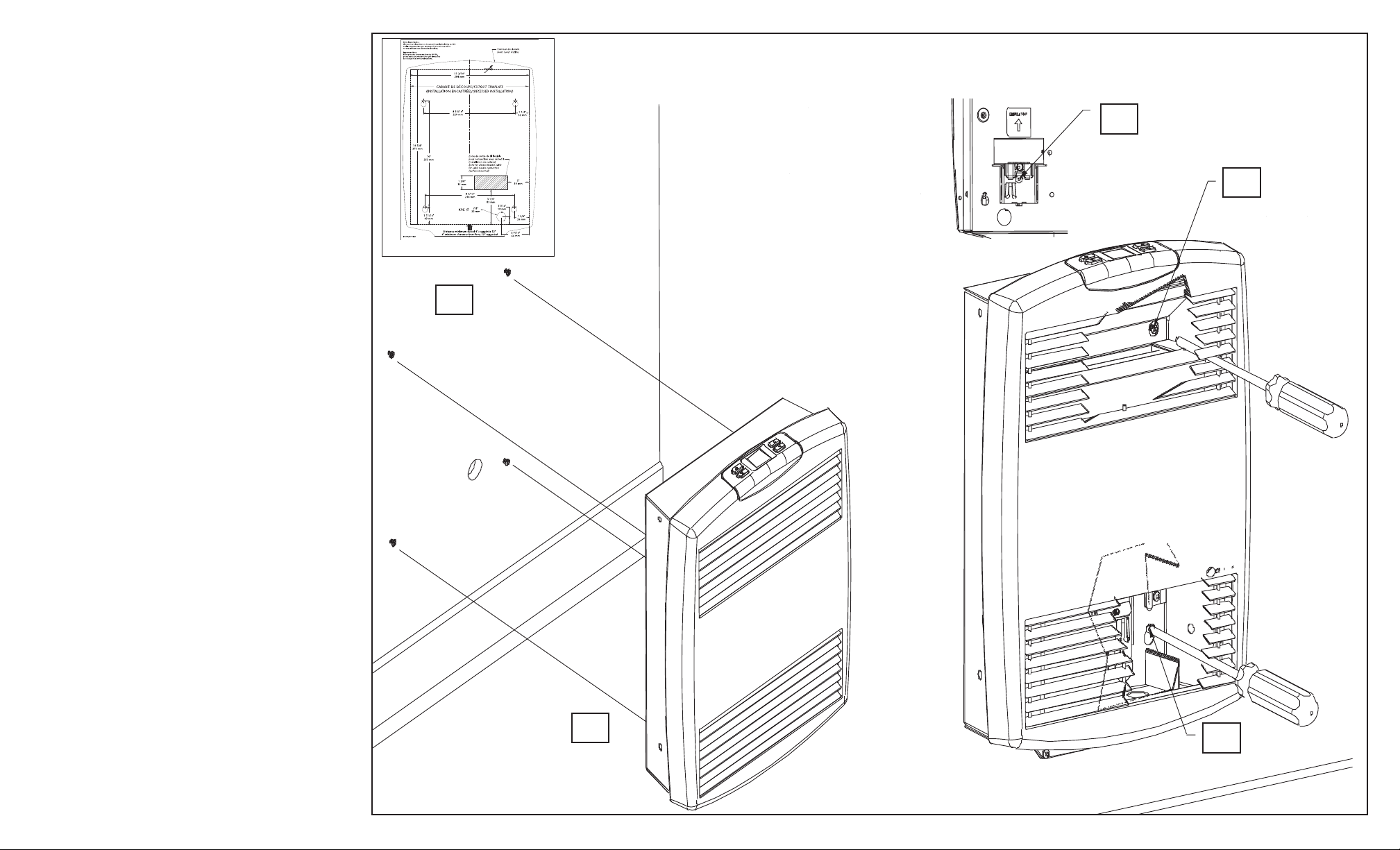
INSTALLATION INSTRUCTION
SURFACE WALL MOUNTING STEPS
without removing the front cover
Figure of Surface wall mounting installation without removing the front cover
1. Use the template provided with the heater.
Allow 4 in. (102 mm) minimum below heater.
Recommended installation height is 12 in. (305 mm)
below the heater for a better temperature regulation.
Locate positionning of the supply wire
and make a 1 in. (25 mm) diameter hole.
Firmly install the 4 screws supplied to the wall.
DO NOT OVERTIGHT SINCE YOU WILL NEED
TO SLIDE THE HEATER AT STEP 3.
2. For an installation with “Loomex” fl exible wire,
use the single-screw wire holder by unscrewing the screw,
make the connections and screw back the wire holder.
Do not let more than 12 in. (305 mm) of loose wire
between the heater and the wall.
For an installation with “BX” cable, follow step 4. b)
of the RECESSED WALL MOUNTING STEPS or
SURFACE WALL MOUNTING STEPS by removing the
front cover.
3. Align the oversized part of the holes with the screws
already on the wall, then slide the heater downward.
Make sure that the 4 screws are well supported at the top
of the keyhole (small part).
4. Once the heater in place, fi nish tightening the 4 screws with
a 5 in. (127 mm) minimum rod screwdriver through the
grilles of the heater as shown. DO NOT USE
A DRILL WITH A SQUARE BIT AT THIS STEP
BECAUSE YOU COULD DAMAGE THE GRILLES.
2.
4.
Template provided
1.
5. Test the heater by pressing the “Hour-glass” button
to activate the boost heating mode. It is possible that a slight
heating smell emerges from the grilles, which is totally
normal and will stop after a few minutes of operation.
3.
4.
Page 3

INSTALLATION INSTRUCTION
RECESSED WALL MOUNTING STEPS or
SURFACE WALL MOUNTING STEPS
by removing the front cover
1. Use the template provided with the heater.
a) Recess wall mounting
- Provide a minimum opening of 2 5/8 in. (67 mm) deep.
HOLE MUST BE CUT PRECISELY.
- Allow 4 in. (102 mm) minimum below heater.
Recommended installation height is 12 in. (305 mm)
below the heater for a better temperature regulation.
b) Surface wall mounting
If you have decided to remove the front cover for a surface
wall mounting installation, follow step 1 of the SURFACE
WALL MOUNTING STEPS without removing the front
cover.
2. Remove the front cover by unscrewing the 2 screws
at the bottom and by sliding the front cover upwards.
3. Disconnect the electronic thermostat from the casing
by pressing the central tab of the black plastic connector.
Put the front cover on a clean surface.
4. a) For an installation with “Loomex” fl exible wire,
use the single-screw wire holder by unscrewing the screw,
make the connections and screw back the wire holder.
Do not let more than 12 in. (305 mm) of loose wire between
the heater and the wall.
b) For “BX” cable,
use the appropriate knock-out (back or bottom of the heater)
with a connector (not supplied). Remove the protection plate
(4 screws), make the connections and put the protection
plate back (4 screws).
5. a) Recessed wall mounting
Install the casing in the wall opening using the recessed
mounting holes on the side or the front of the casing.
Do not try to force the casing in the opening.
b) Surface wall mounting
If you have decided to remove the front cover for
a surface wall mounting installation, follow step 3 and 4
of the SURFACE WALL MOUNTING STEPS
without removing the front cover.
6. Reconnect the electronic thermostat to the casing
by cliping both parts of the black plastic connector together.
Replace the fl at cable in the wire clips.
7. Put the front cover back by sliding it downwards.
The 2 tabs of the front cover fi t into the 2 slots of the casing.
Screw back the 2 bottom screws.
8. Test the heater by pressing the “Hour-glass” button to activate
the boost heating mode. It is possible that a slight heating smell
emerges from the grilles, which is totally normal and will stop
after a few minutes of operation.
Template provided
14 5/8’’
371 mm
4’’ (102 mm)
Minimum
12’’ (305 mm)
Recommended
11 3/16’’
284 mm
4. b)
4. a)
1. a)
or Surface wall mounting installation by removing the front cover
Wall opening
2 5/8’’ (67 mm)
minimum depth
5. a)
5. a)
Figure of Recessed wall mounting
5. a)
A
4. b)
5. a)
3. & 6.
2.
Detail A
7.
2. & 7.
Page 4

USER INSTRUCTION
Appears when the setpoint is displayed
Standby button
Boost heating button
(Hour-glass)
Temperature Display and Setting
The thermostat normally displays the ambient measured
temperature.
The screen is backlit at maximum intensity for 15 seconds
when any button is pressed.
To view the setpoint temperature, press once on either
adjustment button. The setpoint temperature will appear for
5 seconds. A small arrow appears on the top left corner of the
screen.
To change the setpoint temperature,
press the appropriate adjustment button.
Setpoint range: 50 °F to 86 °F (10 °C to 30 °C).
The thermostat using proportional regulation determines the
heating intensity necessary for the electric heating heater to
precisely maintain the ambient temperature according to the
setpoint. The number of fl ames indicates the percentage of heat
calculated by the electronic thermostat, such as 25%, 50%, 75%
and 100%.
To change the temperature display format from °C to °F
or vice versa, press the 2 “Adjustment” buttons simultaneously
for 2 seconds.
Boost Heating (Hour-glass)
For boost heating mode, use the “Hour-glass” button. Press
once to activate this mode and to see the remaining time
fl ashing (“min” is now displayed in the bottom right corner).
Display will stop fl ashing after 5 seconds. While the remaining
time fl ashes, press again the “Hour-glass” button to set the
minutes to 5, 10, 15, 20, 25 or 30. If display does not fl ash any
more, press again the “Hour-glass” button to turn off the boost
heating mode. Whenever needed in the boost heating mode, use
the “Adjustment” button to increase or decrease, by increments
of 1 minute, the remaining time. When in the boost heating
mode ambient temperature is not displayed.
Display Backlit
By default, the screen is backlit at mid-intensity at any time
and at maximum intensity for 15 seconds when you press any
button.
Setting or ambient temperature
Adjustement buttons
Heating intensity (Flame)
Display Backlit (continuation)
To deactivate the mid-intensity backlit, press the “Standby” and
the bottom adjustment buttons simultaneously for 2 seconds.
The letters “bL” appear on the screen. Press one or the other
adjustment buttons until “Off” appears on the screen.
The thermostat will automatically save any changes and return
to normal display if you do not press any buttons for 5 seconds.
Keypad Lock
This feature eliminates unwanted temperature adjustments and
the use of different modes of the thermostat.
Before activating this function, make sure you have set the
temperature setpoint to the desired temperature. Press the
“Standby” and the up buttons simultaneously for 2 seconds.
A pad lock icon appears on the screen to confi rm that your
settings are now locked. Repeat this step to deactivate this
function.
Standby
The standby mode enables thermostat shut down at end
of heating season. Take note that when this mode is activated,
the heater does not heat, no matter the room temperature or
the setpoint. WARNING! The standby mode does not cut the
current to the heater.
For any maintenance, cut power to the heating system at the
main electrical panel to avoid any risk of electrical shock.
To put the thermostat in standby mode, press the “Standby”
button for 2 seconds. The standby icon appears on the screen to
confi rm that the device is in standby.
To return to the heating mode, press the “Standby” button. The
thermostat will then return to normal display.
Power Outage
During a power outage only the setpoint temperature is saved
in memory.
The screen then returns to normal display and any other
functions go back to their default settings.
Note that it can take between 0 and 10 seconds before heating
begins.
Offset of Ambient Temperature
The heater thermostat has been calibrated in laboratory in
order to be precise at ±0.5 °C. Somehow, depending of the
conditions in which it is installed, the ambient temperature
could be different from the one displayed on the heater
thermostat. If you want the thermostat to display the ambient
temperature shown on your thermometer, you must use the
“Offset of Ambient Temperature” function.
Steps to follow (you must have a thermometer):
1. Put the heater in standby mode. (See Standby).
2. Press the “Hour-glass” button for 2 seconds until “Off”
appears on the screen and then “0.0”.
3. To calculate the correction factor
(could be a negative value):
TT = Ambient temperature according to the thermometer
TA = Temperature shown on the heater thermostat
Celsius: (TT - TA) or Fahrenheit: (TT - TA)
2 4
4. Use the adjustment buttons to enter the correction factor
by increments of 0.5
5. Press the “Hour-glass” button in order to quit the “Offset of
Ambient Temperature” function.
6. Press the “Standby” button to get back to normal display.
The correction factor is now taken in to account by the
thermostat. The ambient temperature displayed on the
thermostat should now be the same as the one displayed on
your thermometer.
TROUBLESHOOTING
PROBLEMS TIPS
If the heater stops working in normal mode,
without error code. The display no longer works.
If the heater stops working in normal mode,
without error code. The display still works.
The display shows LO The ambient temperature is equal or below 0 °C (32 °F).
The display shows HI The ambient temperature is above 37 °C (98.5 °F).
The display shows E1 The ambient temperature is below -15 °C (5 °F) or the sensor is cut or not
The display shows E2 The ambient temperature may be above 50 °C (122 °F). The heater may be
The display shows E3 It is likely that something partially obstructs the air outlet and/or the air inlet
The heater cycle in normal mode
without error code.
The heater operates normally
but the display is dark gray and does nothing.
The thermostat does not seem precise at fi rst. An electronic thermostat will seek accuracy from the accumulated historical
Check the circuit breaker of your house.
It is possible that the ambient temperature exceeds the temperature setpoint.
When the ambient temperature falls below the setpoint temperature, the
heater will heat again.
The code LO will disappear when the ambient temperature is above 0 °C
(32 °F). The ambient measured temperature will be displayed again.
The code HI will disappear if the ambient temperature falls below 37 °C
(98.5 °F). The ambient measured temperature will be displayed again.
connected to the power card. If the ambient temperature is below -15 °C
(5 °F), you can press the «Hour-glass» button to bring the ambient
temperature to 0 °C (32 °F), and come back to standard heating mode. If
the sensor wire is damaged, the thermostat will also shown E1 error and the
sensor has to be changed.
partially blocked and infl uences the temperature sensor. It is also possible that
the sensor is shorted. If so, the sensor must be replaced because it is probably
damaged.
of the heater. This causes overheating at the thermostat and a protection is
engaged. The heater can not work, even in boost heating mode, if the error
code is still shown. Let the air inlet and outlet free. The thermostat will return
to normal mode once the temperature has dropped.
The heater is probably completely obstructed, and the thermal protection of
the heater turns off the heat, but not the fan. Let the air inlet and outlet free
and the heater should no longer cycle. If the heater cycles again, it is possible
that the element or even the fan are dirty. Clean with an air stream after closing the circuit breaker in your electrical panel.
The display is defective.
in a given location. After one day, the thermostat has adjusted its core
curriculum to fi t its new environment and should reach its level of precision.
(See Offset of Ambient Temperature).
 Loading...