

Page 1

Page 2 ..... AP50-L1W
Page 8 ..... AP80-L2W_AP100-L2W
Page 15 ..... SBF80-L1W_SBF110-L1W
Page 2

AP50G1 / AP50L1
Page 3
23456
Page 4
Page 5
Page 6
Page 7
Page 8

BATH FAN
User's Manual
AP50G
AP70G / AP80L
AP110G / AP100L
Page 9

READ AND SAVE THESE INSTRUCTIONS.
Read these instructions carefully before installing or using this product!
Dear customers,
Thank you for selecting Aero Pure, which is surely to bring you satisfaction. Read all
instructions before using the unit. Save these instructions please.
WARNING!
TO REDUCE THE RISK OF FIRE, ELECTRIC SHOCK, OR INJURY
TO PERSONS, OBSERVE THE FOLLOWING:
1. Use the unit only in the manner intended by the manufacturer. If you have questions,
contact the local agent or the manufacturer.
2. Before servicing or cleaning the unit, switch power off at service panel and lock the
service disconnecting means to prevent power from being switched on accidentally. When
the service disconnecting means cannot be locked, securely fasten a prominent warning
device, such as a tag, to the service panel.
3. Installation work and electrical wiring must be done by qualified person(s) in accordance
with all applicable codes and standards, including fire-rated construction.
4. For the purpose of avoiding any dangerous gas leaking into your house, the duct must
not be laid together with the vent-pipe of air-fueled water heater into the same flue.
5. When cutting or drilling into wall or ceiling, do not damage electrical wiring and other
hidden utilities.
6. Ducted fans must always be vented to the outdoors.
7. NEVER place a switch where it can be reached from a tub or shower. To reduce electric
troubles, water must be prevented from going into the housing. The fan must not be
installed at the place where suffers severe water leakage.
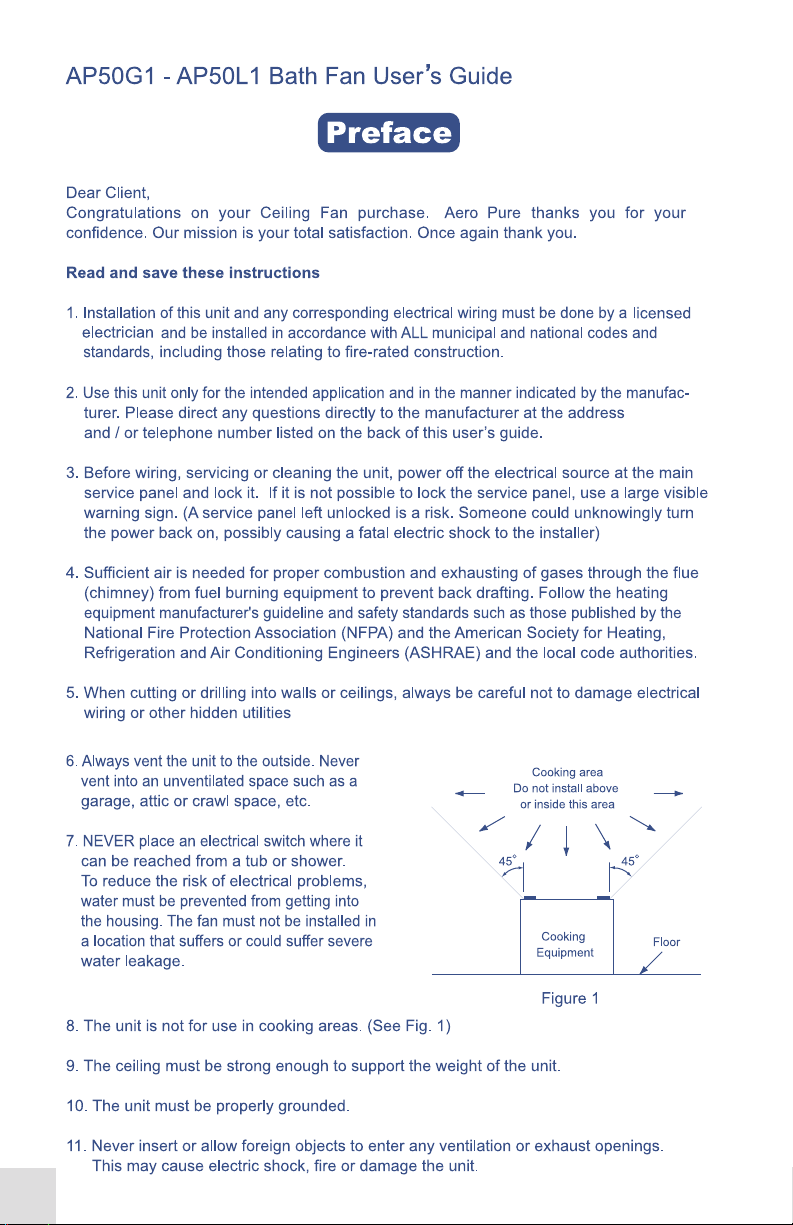
Cooking area
8. Not for use in the cooking area (Figure 1).
Do not install above
or inside this area
9. Not for use in the shower cubicle generally.
45
10. The ceiling must be strong enough to support
the weight of the fan.
Cooking
11. The fan must be properly grounded.
Figure 1
Equipment
12. Do not insert or allow foreign objects to enter any ventilation or exhaust opening as this
may cause an electric shock, or damage the unit.
2
45
Floor
Page 10

13. Do not block air intakes or exhaust in any manner.
14. Do not switch on/off frequently when in use. Shut off power if in long vacancy.
15. Shut off power urgently if anything unusual occur when in operation and contact with local
agent or specialized maintenance shop.
16. When clean the fan, do not use corrosive chemical liquid. Do not rinse plastic parts in
water the temperature of which is higher than 60 .
17. For supply connections use No. 14 AWG or larger wires suitable for at least 90 (194 ).
o
c
o
coc
18. Do not use outdoors.
19. To reduce the risk of fire, use only PL type 26W lamp. For the nightlight use a maximum
4W lamp. (Model: AP80L1, AP80L2, AP80L3, AP100L1, AP100L2, AP100L3)
20. Ceiling Insert Fans must not be installed in a ceiling with an insulation value that is greater
than R40.
21. TYPE IC-INHERENTLY PROTECTED.
22. To reduce the risk of injury to persons, install fan at least 2.1m (7 feet) above the floor.
23. These fans (model number is: #L1, #G2, #G6) are acceptable for use over a bathtub or
shower when installed in a GFCI protected branch circuit. Other models are not for use over
a tub or shower.
CAUTION
1. For general ventilating use only. Do not use to exhaust hazardous or explosive materials
and vapors.
2. This product is designed for installation in flat ceilings only and for household use only. Do
not mount it on a sloping ceiling or a vertical wall.
3. To avoid motor bearing damage and unusual noise and/or unbalanced impellers, keep
drywall spray, construction dust, etc. off the unit.
4. It is highly recommended to make preparation for unit installation when you retrofit your
bathroom.
5. Please read specification label on product for further information and requirements.
SAVE THESE INSTRUCTIONS
3
Page 11

TO INSTALL, FOLLOW THE STEPS AS FOLLOWING:
INSTALLATION
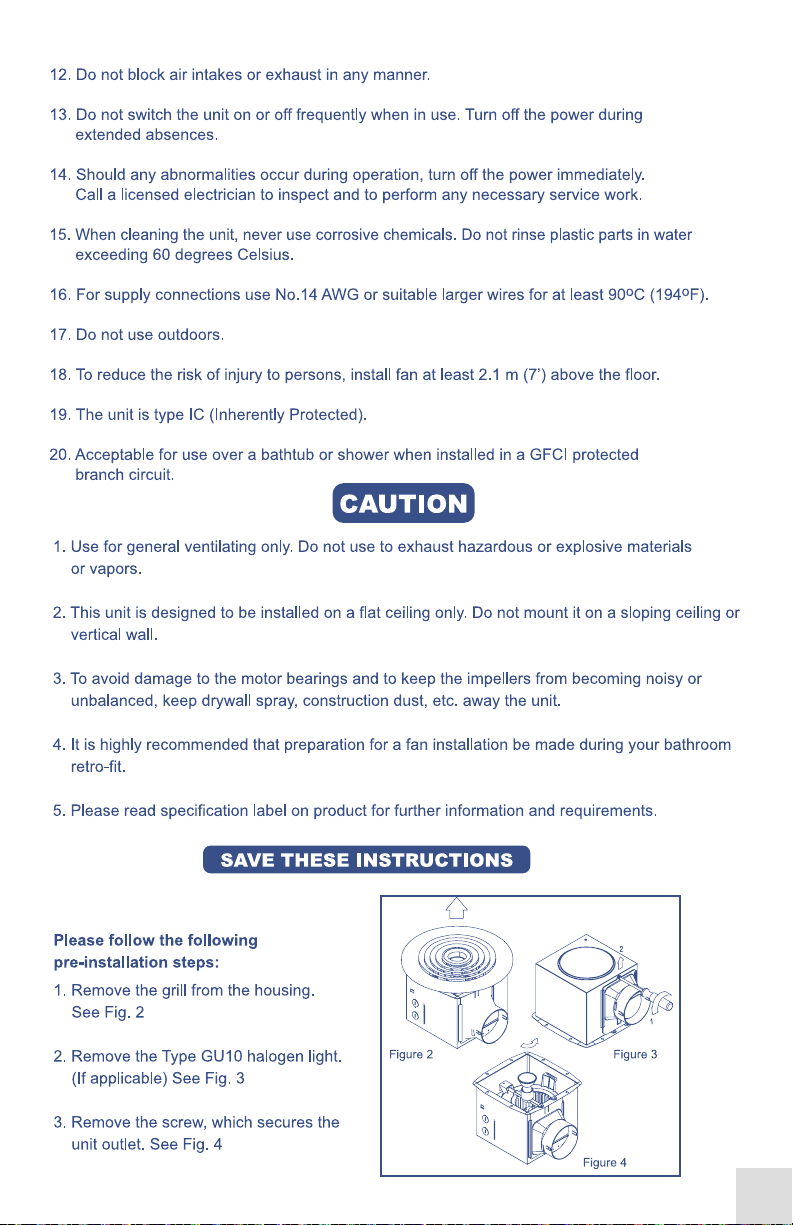
1. PREPARATION FOR
INSTALLATION
(Figure 2)
The unit should be ceiling insert
only. The size of joists should be at
least 2" wide and 4" high. The
space between two joists should
be 16". From the above surface of
the suspended ceiling there should
be minimum 9" distance to the
roof.
2. INSTALLATION
1) Remove the grill by a little press
the spring inside and take off the
fascia from the housing (Figure 3).
2) Remove the wire box cover from
the housing and install the 3
brackets onto the housing in the
very positions (Figure 3).
3)Position housing between joists
and extend mounting brackets.
Mark the top of keyhole for screws
on all mounting brackets. When
fixing the brackets onto ceiling
joists, make sure to reserve the
suspended ceiling thickness
between bottom edge of housing
and ceiling joists. After the final
ceiling work, the bottom edge of
housing should be flush with
suspended ceiling (Figure 4).
Power supply
protective tube
Ceiling
Housing
Wire box
Fan outlet
Wire box cover
••
•••••
Grill
Figure 2
Ceiling joist
Hanger bar
Figure 3
Figure 4
Distance of
suspended
ceiling
Figure 5
Note: Make sure the distance from
the fan outlet to the wall must be
less than the length of the ventiduct
before installing.
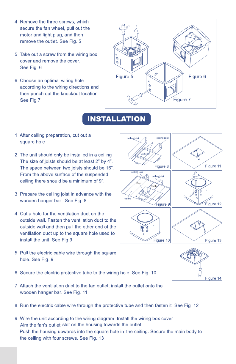
4)Remove housing temporarily, and pound screws partially into joists at all marked locations
(Figure 5).
4
Page 12

5) Hang housing onto the screw and
pound all the screws tight. Connect the
end of wire in the wire box with power
wire outside according to the wire diagram, then replace the wire box cover
after putting the protective tube
for the power wire in the very position.
Fix the ventiduct tightly onto the fan
outlet (Figure 6).
Note: To be most effective, please keep the ventiduct as straight as possible.
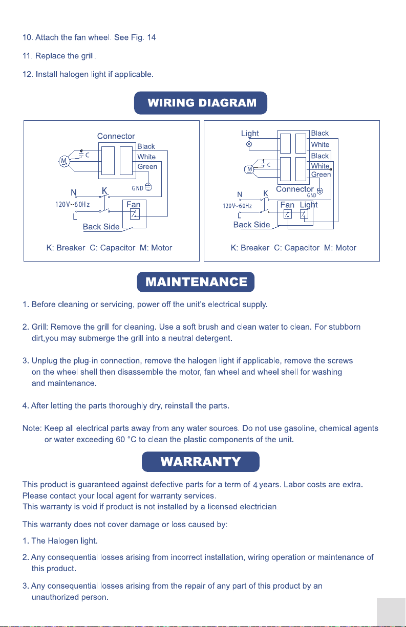
Wire Diagram
Figure 6
K:Breaker C:Capacitor M:Motor K:Breaker C:Capacitor M:Motor
AP50G / AP70G / AP110G
6) Replace the grill after finishing the ceiling (Install the light if has).
AP80L / AP100L
MAINTENANCE
1. Shut off power before servicing or cleaning.
2. Remove the grill. Soft brush and clean water can be used for cleaning the grill. For the dirt
that cannot be wiped off easily, you may immerse it into the neutral detergent first.
5
Page 13

3. Unplug the plug-in connection and remove the 4 screws on the wheel shell (first remove light,
night-light and the reflector if there are) then disassemble the motor, fan wheel, wheel shell for
washing and maintenance (Figure 7).
Note: Electric parts are prohibited
from touching water. Do not use
gasoline, chemical reagent or hot
water higher than 60 centigrade
degree to clean the plastic components.
4. After the cleaning and maintenance,
install all the parts in reverse after they
become dry thoroughly.
Plug-in
Figure 7
WARRANTY
The product is warranted against failure for a period of 4 years.
and bring the original invoice to your local agent for warranty services.
This warranty is null and void if product is not installed by a Licensed Electrician and Aero Pure
LLC assumes no responsibility for any and all loss.
This warranty does not cover damage or lose caused by:
1) Light lamp and night lamp (if there are).
2) Any consequential losses arising from incorrect installation or operation or maintenance of
this product.
3) Any consequential losses arising from incorrect wiring of this product.
4) Any consequential losses arising from repairing of any part of this product by unauthorized
persons.
Labor costs extra
. Please keep
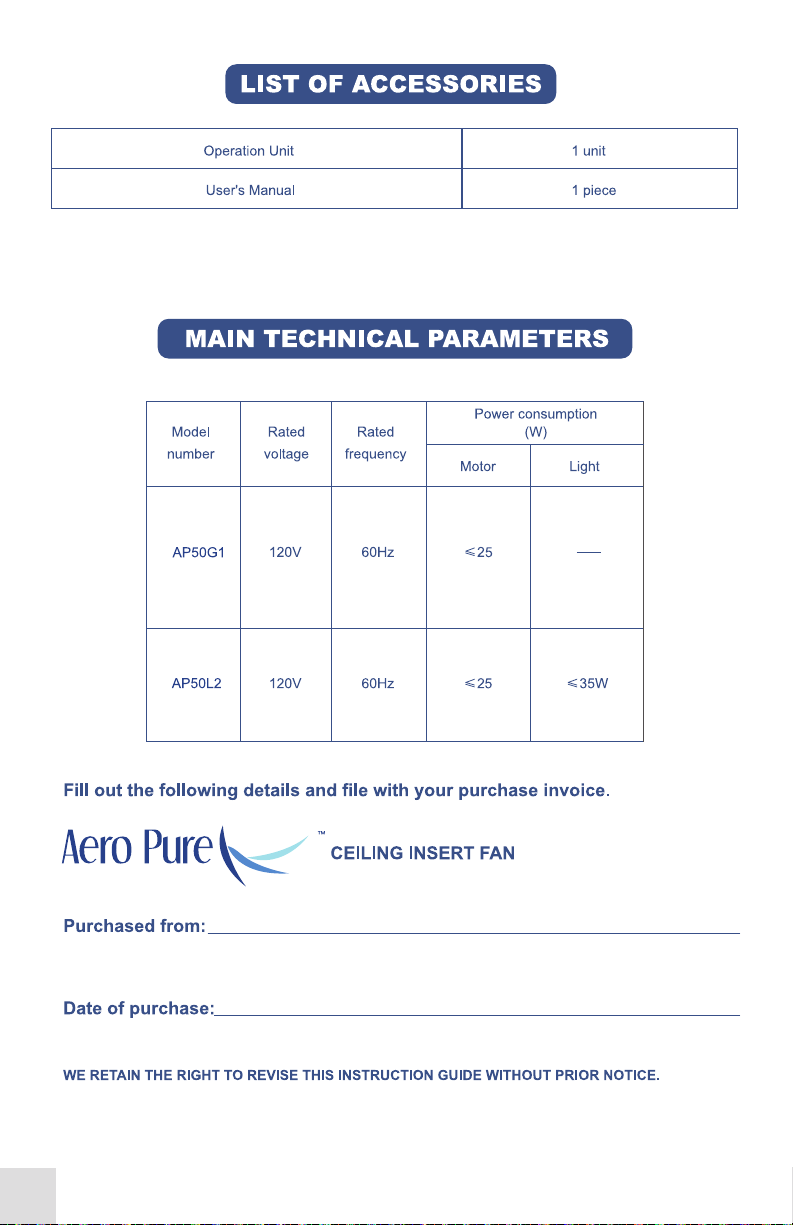
LIST OF ACCESSORIES
Operation Unit 1 unit
Bracket for Installation 1 set
User's Manual 1 piece
26W PL and 4W nightlight bulb (in model AP80L1,
AP80L2, AP80L3, AP100L1, AP100L2, AP100L3 only)
1 set
6
Page 14

Model
number
MAIN TECHNICAL PARAMETERS
Power consumption
Rated
voltage
Rated
frequency
Motor
(W)
Light
Night
light
Airflow (CFM)
AP50G
(2,3,4,5,6...)
AP70G
(1,2,3,4,5,6...)
AP110G
(1,2,3,4,5,6...)
AP80L1
AP80L2
AP80L3
AP100L1
AP100L2
AP100L3
120V 60Hz ≤20 50
120V 60Hz ≤35
120V 60Hz ≤40
120V 60Hz ≤25
120V 60Hz ≤40
≤26, PL
≤26, PL
4
4
Fill out the following details and file with your purchase invoice
BATH FAN
70
110
80
80
70
100
Purchased from
Date of purchase
WE KEEP THE RIGHTS TO REVISE THIS INSTRUCTION WITHOUT ANY PRIOR NOTICE.
7
Page 15

BATH FAN
User's Manual
SBF80L1 / SBF80G
SBF110L1 / SBF110G
Page 16

READ AND SAVE THESE INSTRUCTIONS.
Read these instructions carefully before installing or using this product!
BEFORE INSTALLATION
WARNING!
TO REDUCE THE RISK OF FIRE, ELECTRIC SHOCK, OR INJURY
TO PERSONS, OBSERVE THE FOLLOWING:
1. Use this unit in the manner intended by the manufacturer. If you have any
questions, please contact the manufacturer .
2. Before servicing or cleaning unit, switch power off at service panel and lock the
service disconnecting means to prevent power from being switched on accidentally.
When the service disconnecting means cannot be locked, securely fasten a
prominent warning device, such as a tag, to the service panel.
3. Installation work and electrical wiring must be done by qualified person(s) in
accordance with all applicable codes and standards, including fire-rated construction.
4. Sufficient air is needed for proper combustion and exhausting of gases through
the flue (chimney) of fuel burning equipment to prevent back drafting. Follow the
heating equipment manufacturer’s guideline and safety standards such as those
published by the National Fire Protection Association (NFPA), and the American
Society for Heating, Refrigeration and Air Conditioning Engineers (ASHRAE), and
the local code authorities.
5. When cutting or drilling into wall or ceiling, do not damage electrical wiring and
other hidden utilities.
6. Ducted fans must always be vented to the outdoors.
7. If this unit is to be installed over a tub or shower, it must be marked as appropriate
for the application and be connected to a
GFCI (Ground Fault Circuit Interrupter) –
protected branch circuit.
8. NEVER place a switch where it can be
Cooking area
Do not install above
or inside this area
reached from a tub or shower.
45 45
9. This fan must be properly grounded.
10. Do not use in the cooking area (Figure. 1).
11.Do not block the air intakes or exhaust.
Figure 1
Cooking
Equipment
2
Floor
Page 17

12. Power supply wiring is to be No. 14 AWG wire or larger (suitable for at least
90C (190F) ).
13. Not for use outdoors.
14. For the lighted unites, use only PLC type 26W lamps and a maximum of 4W
night lamp for lighting.(SBF80L, SBF110L)
15. The fan must not be installed in a ceiling with an “R” rating greater than 40.
16. The fan is type IC (Inherently Protected).
17. To reduce the risk of injury, install the fan at least 2.1m (7 feet) above the floor.
18. Acceptable for use over a shower or tub when installed in a GFCI protected
branch circurt.
19. The fan should not be turned on and off rapidly nor should it be left running
continuously.
20. Do not clean the fan with corrosive chemicals nor water in excess of 60C
(140F).
21. If the fan is not operating properly, shut the power off immediately, and have
a certified inspect it and have it serviced as required.
22. These fan must be mounted to structural members that are strong enough to
support the fan’s weight.
23. Do not allow foreign objects to enter the fan; this could result in electric shock
or fan damage.
CAUTION
1. For general ventilating use only. Do not use to exhaust hazardous or explosive
materials and vapors.
2. This product is designed for installation in flat ceilings only. Do not install it in a
sloping ceiling or in a wall.
3. To avoid motor bearing damage and noisy unbalanced impellers keep
construction material / dust from entering the fan.
4.Please read specification label on the product for further information and
requirements.
5."WARNING":To Reduce The Risk Of Fire Or Electric Shock,Do Not Use This
Fan With Any Solid-State Speed Control Device.
3
Page 18

PLEASE INSTALL AS THE FOLLOWING STEPS:
INSTALLATION
The unit should only be installed
in a ceiling. The size of joists
should be at least 2” wide and 4”
high . The space between two
joists should be 16”. From the
above surface of the suspended
ceiling there should be minimum
9” distance to the roof. (Figure 2)
Select the suspension brackets
as shown in (Figure 3)
1. Remove the grille by gently
squeezing the wire springs and
extracting them from the slots in
the housing.
2. Remove the wire box cover
and install the 3 brackets on
the fan housing. (Figure. 3-1,
Figure. 3-2).
3. To install the housing in the
ceiling, position it between the
joists and extend the brackets
to the adjacent joists.. Mark the
screw locations (at the top of
the keyhole on each bracket)
on the joists.
Power supply
protective tube
Ceiling
Housing
Wire box
Fan outlet
Wire box cover
Ceiling joist
Grill
Hanger bar
Joists
A
Spacing A on center joist Insert Suspension bracket
16 inches Figure 3-1
24 inches Figure 3-2
Figure 4
Figure 2
Figure 3
Note: make sure to allow the
appropriate depth for the
particular ceiling type. The
bottom edge of the housing
should be flush with the ceiling.
(Figure 4)
4
Distance of
suspended
ceiling
Figure 3-1 Figure 3-2
Page 19

4. Remove the housing and drive
the screws part way into the joists
at the marked locations.
5. Mount the housing using the
screws in the joists and then
secure them tightly. Make all the
electrical connections in the wire
box, per the wiring diagram, and
attach the wire box cover. Attach
the discharge duct tightly onto the
fan outlet.
Note: In order for the fan to
operate efficiently, keep the
discharge duct as straight as
possible.
6. To complete the installation,
install the lamps (if applicable)
and mount the grill.
Wiring Diagram
Figure 5
Figure 6
For Fan/Light Combination For Fan only Units
5
Page 20

MAINTENANCE
1. Turn the power off and lock it out prior to servicing or cleaning.
2. To clean the grille, first remove it from the fan then use a soft brush and clean water
to remove the dirt. If the dirt is not easily removed, wash with a neutral detergent.
3. In order to remove the impeller
and housing for maintenance, first
remove the light, night light and
reflector (if applicable). Then unplug
the electrical connection and remove
the 4 screws that secure the fan
assembly to the housing. To clean
the impeller and housing, remove
the motor and then wash with water
or a neutral detergent, as required.
Note: Keep all electrical components away from water. Do not use corrosive chemicals
or water in excess of 60C (140F) to clean plastic parts.
Plug-in
Figure 7
WARRANTY
The product is warranted against failure for a period of 4 year (excluding Light Lamp).
Labor cost extra. Please keep and bring the original invoice to your local agent for
warranty services.
This warranty does not cover damage or lose caused by:
1) Light lamp (if there are).
2) Any consequential losses arising from incorrect installation or operation or
maintenance of this product.
3) Any consequential losses arising from incorrect wiring of this product.
4) Any consequential losses arising from repairing of any part of this product by
unauthorized persons.
6
Page 21

LIST OF ACCESSORIES
Operation Unit 1 Unit
Bracket for Installation
User's Manual
26W energy saving Lamp ( in model SBF80L, SBF110L )
4W night lamp ( in model SBF80L, SBF110L )
MAIN TECHNICAL PARAMETERS
Model
number
SBF80G
Series
(1、2、3、
4、5、6…)
SBF110G
Series
(1、2、3…)
Voltage Frequency
120V
120V
60Hz
60Hz
Power consumption
Motor
≤ 25
≤ 30
(W)
Light
Night
light
5 Pieces
1 Piece
1 Piece
1 Piece
Speed
(RPM)
660
780
Air deliver
(CFM)
80
110
SBF80L1
SBF110L1
120V
120V
60Hz ≤ 25
60Hz ≤ 30
Type PLC
≤26W
Type PLC
≤26W
4
4
660
780
80
110
7
Page 22

Aero Pure Fans LLC
3270 Associate Drive
Suite B
North Charleston, SC29418
Office: 843 377 8642
Fax: 843 377 8643
 Loading...