

Page 1
Floor Heating System
Therma Cable
INSTALLATION GUIDE
September 2012 Edition
Page 2

Page 3

1. Therma Cable Floor Heating System . . . . . . . . . . . . . . . . 4
1.1 General Information . . . . . . . . . . . . . . . . . . . . . . 4
1.2 Always . . . . . . . . . . . . . . . . . . . . . . . . . . . . 6
1.3 Never . . . . . . . . . . . . . . . . . . . . . . . . . . . . . 6
2. Technical information. . . . . . . . . . . . . . . . . . . . . . . . 7
2.1 Surface Area and Power Output of Therma Cable Products . . . . 7
2.2 Insulation Test . . . . . . . . . . . . . . . . . . . . . . . . . 8
2.3 Resistance Test. . . . . . . . . . . . . . . . . . . . . . . . . 9
3. Types of Heating and Floor Covering . . . . . . . . . . . . . . . .10
3.1 Floor Warming. . . . . . . . . . . . . . . . . . . . . . . . .10
3.2 Radiant Floor Heating . . . . . . . . . . . . . . . . . . . . . 10
3.3 Typical Floor Coverings. . . . . . . . . . . . . . . . . . . . .11
4. Installation Instructions. . . . . . . . . . . . . . . . . . . . . . .12
4.1 Planning Work. . . . . . . . . . . . . . . . . . . . . . . . .12
4.2 Preparing the Subfloor . . . . . . . . . . . . . . . . . . . . . 13
4.3 Marking the Floor . . . . . . . . . . . . . . . . . . . . . . . 13
4.4 Installing the Therma Cable Floor Heating System . . . . . . . . 14
4.5 Installing the Temperature Sensor . . . . . . . . . . . . . . . .17
4.6 Applying Self-Levelling Cement . . . . . . . . . . . . . . . . .18
4.7 Connecting the System. . . . . . . . . . . . . . . . . . . . .19
4.8 Measuring Resistance and Measures’ table . . . . . . . . . . . .20
4.9 Using the Therma Cable System . . . . . . . . . . . . . . . . 20
Table of Content
5. Temperature Regulation . . . . . . . . . . . . . . . . . . . . . .21
6. FAQ . . . . . . . . . . . . . . . . . . . . . . . . . . . . . . . . .22
6.1 Floor Heating System . . . . . . . . . . . . . . . . . . . . . 22
6.2 Installation . . . . . . . . . . . . . . . . . . . . . . . . . . 23
7. Expert Tips: Installation and Floor Covering . . . . . . . . . . . . 25
7.1 Installation Tips . . . . . . . . . . . . . . . . . . . . . . . . 25
7.2 Floor Covering Tips . . . . . . . . . . . . . . . . . . . . . . 25
8. Warranty . . . . . . . . . . . . . . . . . . . . . . . . . . . . . .26
8.1 Warranty Statement . . . . . . . . . . . . . . . . . . . . . . 26
3
Page 4
1.1 General Information
IMPORTANT!
The installation must meet the following building codes, as applicable:
– Canadian Electrical Code (CSA C22.1)
– American National Electricity Code (ANSI/NFPA 70)
– Any other national or local code
The Therma Cable floor heating system is composed of a heating cable along
with a lead for connection to an electrical power source. Therma Cable meets
the following in The Canadian Electrical Code standard: series heating cables set.
IMPORTANT!
Shut off power supply to the floor heating system to prevent electrical shock.
Important informations
– The Therma Cable floor heating system is designed exclusively for interior floor
heating. The system is not designed for snow melting or any other outdoor
uses;
– Therma Cable is mainly designed to complement a building’s primary heating
source by serving as a secondary (floor warming) or primary room heat source
(radiant floor heating);
1. Therma Cable Floor Heating System
– Refer to Section 3 for instructions on heating a room using the Therma Cable
system only;
– Floor temperature varies based on insulation and floor characteristics;
– The Therma Cable system can be installed under a shower floor only if the floor
is ceramic or natural stone. A waterproof membrane must be used to maintain
the heating cables in a dry environment. Canada: A ground fault circuit inter-
rupter (GFCI) must be used with this heating device in bathrooms. USA: A ground
fault circuit interrupter (GFCI) must be used with this heating device in bathrooms
and in hydromassage bathtub locations;
– The Therma Cable system must be embedded in cement or an equivalent
binder (cement glue, ceramic glue or self-levelling cement);
– The system must be installed by a master electrician who is: able to evaluate
proper electrical resistance and wattage, familiar with installation-related risks
and knowledgeable about construction techniques as well as the installation
and use of the Therma Cable floor heating system;
– The system is only one step in the floor construction process. Each trade is
responsible for the quality of its work and must ensure that the work performed
by the previous tradesman has been duly completed according to code. All
tradesmen are engaged in the installation process and share joint responsibility
for it.
4
Page 5
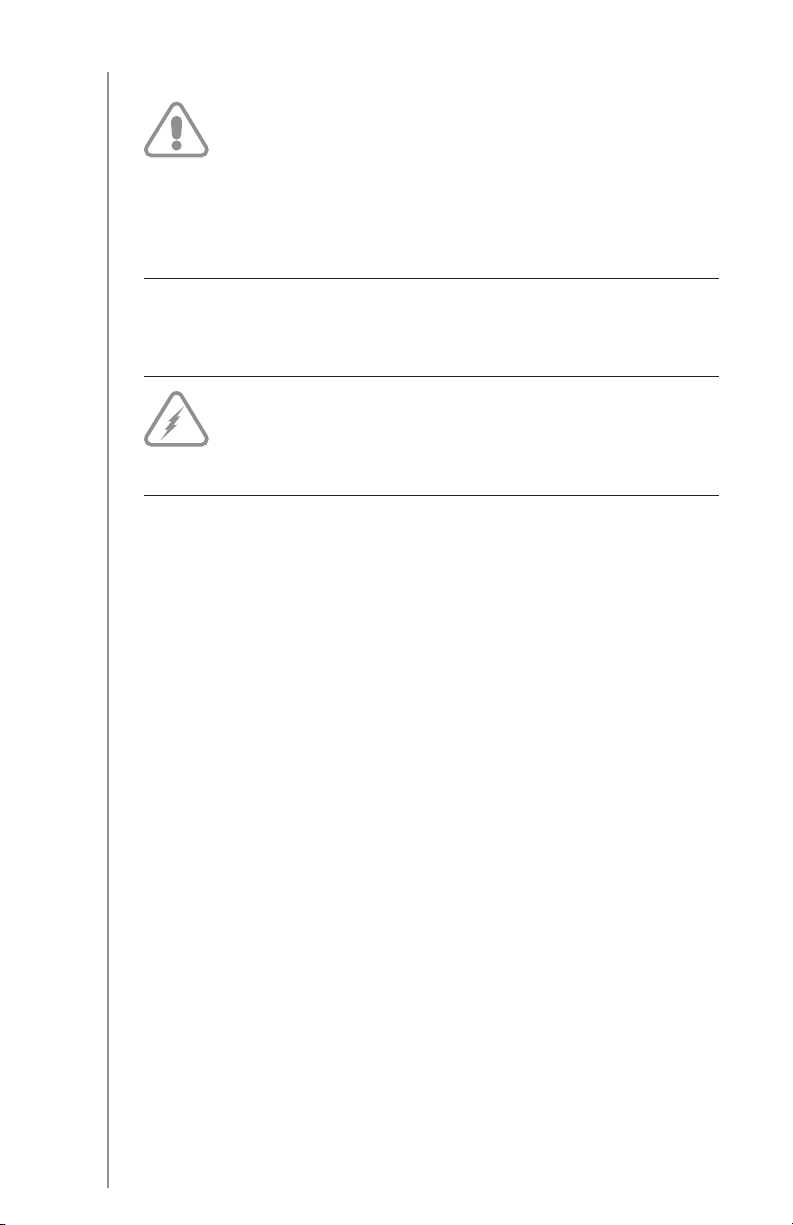
Components
Fig. 1.1
Technique for interlocking the plastic strappings
Fig. 1.2
5
Page 6

1.2 Always
– Read this guide in full before installing the product;
– Install the Therma Cable system with a regulating device;
– Use copper wires only;
– Perform the mandatory tests described in this guide and record readings on the
table of measures;
– Only use cement or an equivalent binder compatible with floor heating systems
(cement glue, ceramic glue, self-levelling cement);
– Ensure that the black heating cable is completely embedded in cement or an equiv-
alent binder (cement glue, ceramic glue, self-levelling cement);
– Ensure that the voltage supplied equals the nominal voltage of the Therma Cable
system;
– Repair the product only using the Therma Cable repair kit available at your autho-
rized Ouellet Canada Inc. dealer;
– Consult Ouellet Canada Inc.’s team of technical specialists for any questions or for
more information;
– Install Therma Cable at temperatures over 5 °C (40 °F).
– Heating cables must be at least 13 mm (½”) away from any combustible surface.
– Metal structures or materials used for the support of or on which cables or sets are
installed be grounded in accordance with the Canadian Electrical Code (CSA C22.1
Section 10 and National Electrical Code).
– The installer of series heating cable sets must inspect and remove damaged or
defective heating cable sets before they are covered or concealed;
– Installer of series heating cable sets must mark the appropriate circuit breaker
reference (label) indicating which branch circuit supplies the circuit to those electric
heating cables.
6
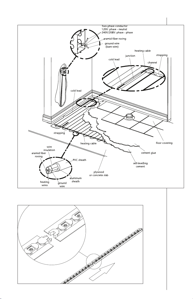
1.3 Never
– Install Therma Cable sections so that the heating cables are less than 76 mm (3”)
from each other. The temperature could be too high and could cause damages;
– Shorten or alter any part of the heating cable (Fig. 1.3);
– Cross, overlap, or stack heating cables (they must not touch);
– Connect a 120V product to a 240V/208V power source;
– Use a bending radius under 20 mm (¾”);
– Install a temperature regulator (thermostat or other) where it is accessible from the
shower or bath (install at least 1 m [3’ 4”] away);
– Staple heating cable or floor sensor end to the subfloor (Fig. 1.3);
– Install the Therma Cable system if the safety seal is broken;
– Install the Therma Cable system under a closet or fixed items.
– Series heating cable sets shall not extend from beyond the room or area in which
they originate;
– Series heating cable sets are not to be installed in walls.
– Exceed the 15 Amp limit per thermostat or power unit if you intend to add a OTR
product to one of them. Please refer to the related OTR table products to deter-
mined if the amperage limit was reached or not, by adding a OTR product to the
thermostat or power unit (or relay). If the amperage limit is over 15 Amp then you
will need to add a power unit for the additional product needed in this room.
Page 7
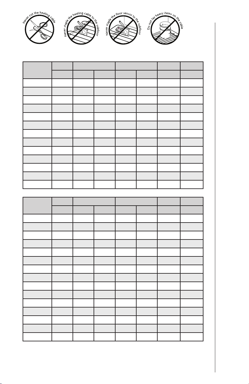
Fig. 1.3
2.1 Surface Area and Power Output of Therma Cable Products
Product #
120V
OTR0082 85 9.80 32 0.70 8 0.71 8.590
OTR0122 120 12.20 40 0.90 10 1.00 4.770
OTR0152 150 15.90 52 1.20 13 1.25 3.050
OTR0172 170 18.30 60 1.40 15 1.41 2.192
OTR0242 240 24.40 80 1.90 20 2.00 1.239
OTR0302 300 30.50 100 2.40 25 2.50 0.786
OTR0362 360 36.60 120 2.80 30 3.00 0.548
OTR0422 420 42.70 140 3.30 35 3.50 0.400
OTR0472 475 48.80 160 3.70 40 3.96 0.310
OTR0602 600 61.00 200 4.60 50 5.00 0.196
OTR0722 720 73.20 240 5.60 60 6.00 0.137
OTR0842 840 85.30 280 6.50 70 7.00 0.100
OTR0962 960 97.50 320 7.40 80 8.00 0.077
Power Length
Watts m ft. sq. m sq. ft. A Ohm / m
Surface
Amperage
Resis
tance
2. Technical information
Product #
240/208V
OTR0170 170 18.30 60 1.40 15 0.71 8.590
OTR0240 240 24.40 80 1.90 20 1.00 4.770
OTR0300 300 30.50 100 2.40 25 1.25 3.050
OTR0360 360 36.60 120 2.80 30 1.50 2.192
OTR0420 420 42.70 140 3.30 35 1.75 1.587
OTR0475 475 48.80 160 3.70 40 1.98 1.239
OTR0600 600 61.00 200 4.60 50 2.50 0.786
OTR0720 720 73.20 240 5.60 60 3.00 0.548
OTR0840 840 85.30 280 6.50 70 3.50 0.400
OTR0960 960 97.50 320 7.40 80 4.00 0.310
OTR1080 1080 109.70 360 8.40 90 4.50 0.242
OTR1200 1200 121.90 400 9.30 100 5.00 0.196
OTR1440 1440 146.30 480 11.10 120 6.00 0.137
OTR1600 1600 170.70 560 13.00 140 6.66 0.100
OTR1920 1920 195.10 640 14.90 160 8.00 0.077
Power Length
Watts m ft. sq. m sq. ft. A Ohm / m
Surface
Amperage
208 V = 75% of wattage at 240 V
Resis
tance
7
Page 8
2.2 Insulation Test
cold lead
Measure Therma Cable’s insulation resistance at each step using a
megohmeter (Fig. 2.2) and record readings on the measures’ table (this
label is available at the opening of the product).
IMPORTANT!
For the warranty to be valid, fill out the measures’ table and ensure that the
10 readings have been correctly noted.
A qualified electrician must measure the system’s insulation resistance as follows:
– Use a calibrated megohmeter only;
– Measure insulation resistance at the free end of the cold lead, between the
phase conductor and ground;
Fig. 2.2
CAUTION! Dangerous Test
– Write the reading in the measures’ table;
– This reading must be over 1,000,000 ohms;
– If the reading is under 1,000,000 ohms, stop work and contact
Ouellet Canada Inc.’s technical specialists at 1 800 463-7043.
8
Page 9

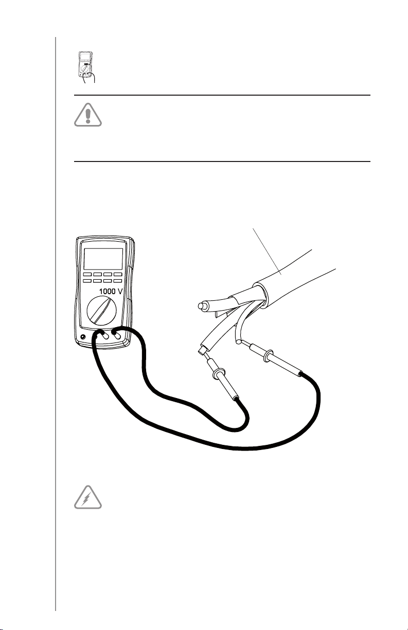
2.3 Resistance Test
cold lead
Measure the resistance of the Therma Cable heating cable at each step
using a multimeter (Fig. 2.3) and record readings on the measures’ table.
IMPORTANT!
For the warranty to be valid, fill out the measures’ table and ensure that the
10 readings have been correctly noted.
A qualified electrician must measure the system’s resistance as follows:
– Use a calibrated multimeter only;
– Measure resistance at the free end of the cold lead, between the two phase
conductors;
Fig. 2.3
– Write the reading in the measures’ table;
– Verify the heating cable integrity by comparing your reading to the value on
the cold lead label;
– If your reading is off or very different than the nominal resistance (see Table 2.1)
at any step, stop work and contact Ouellet Canada Inc.’s technical specialists
at 1 800 463-7043.
9
Page 10

The Therma Cable floor heating system can be used for two purposes maximizing
comfort.
Used as a secondary heat source (floor warming), it can help keep floor temperature comfortable year round. Used as a primary room heat source (radiant floor
heating), it provides uniform, comfortable, and enveloping warmth. For the latter
use, it is important to follow the specific recommendations outlined below.
In light of environmental factors beyond Ouellet Canada Inc.’s control—including
thermal insulation, heated area, floor covering emissivity, heat loss, and more—
we cannot guarantee that the Therma Cable system will provide a completely
uniform surface temperature in all cases, no matter how careful the installation.
Consequently, Ouellet Canada Inc. cannot be held liable for any discomfort (e.g.,
a cold area on the floor) caused by site-specific deficiencies.Ouellet Canada Inc.
liability is limited to the performance of its products.
3.1 Floor Warming
This type of heating is designed to enhance comfort and/or supplement the room’s
main heat source. It helps keep the floor at a pleasant temperature at all times.
Installing this type of system is very easy: simply unroll the Therma Cable on
the floor, maintain it with the installation strappings, embed the heating cable in
cement or an equivalent binder (cement glue, ceramic glue, self-levelling cement)
and install the floor covering. Use the floor coverings listed in Section 3.3 and
connect the Therma Cable system to an appropriate thermostat, described in
Section 5.
3.2 Radiant Floor Heating
Therma Cable can be used as the room’s primary heat source. It can heat the
room using the Therma Cable system only. Proceed as follows:
– Connect the system to an ambient temperature regulator;
3. Types of Heating and Floor Covering
– Calculate heat loss to ensure the system has enough power to heat the room;
– Sufficient insulation under the subfloor is very important. This insulation is to be
sure that the heat will rise into the room to be heated.
– Make sure to have a floor covering that meets the specifications listed in
Table 3.3.
10
Page 11

IMPORTANT!
Do not install a radiant floor heating system on a noninsulated or poorly
insulated subfloor, or over a crawl space.
The efficiency of this type of primary room heating system will depend on
factors such as available surface of the room to be covered with heating cable
(or sufficient percentage of the surface to be heated), heat conductivity of
the floor covering, insulation on outside walls, etc. We recommend that you
verify these points and seek professional advice before investing time and
money.
3.3 Typical Floor Coverings
IMPORTANT!
The thermal resistance of the floor covering must not exceed R = 1.40
(RSI = 0.246). There is no such limit for the subfloor.
Table 3.3 Thermal resistance values for floor coverings
Typical floor covering
Vinyl tiles 0.20 0.035
Linoleum 0.22 0.039
Ceramic 0.25 0.044
Low-pile carpet 0.70 0.123
Parquet flooring 0.70 0.123
Floating floor 10 mm to 16 mm (3/8” to 5/8”) 0.70 0.123
Wood on lathes (strapping)* 2.10 0.368
* The floor covering highlighted in grey is prohibited.
Thermal resistance
R RSI
IMPORTANT!
For engineered wood floorings, laminated hardwood flooring, vinyl coverings,
and linoleum glued to a concrete surface, consult your floor covering
manufacturer to ensure they are compatible with floor heating systems.
11
Page 12

4.1 Planning Work
10'
Materials provided by Ouellet Canada Inc.
– Therma Cable heating cable kit
– Installation strappings
– Installation instructions
– Service panel label
– Floor temperature sensor
Material required
– Temperature control with GFCI (available at Ouellet Canada Inc.)
– Cable check tester (available at Ouellet Canada Inc.)
– Stapler
– Protective glasses
– Measuring tape
– Broom
– Felt marker
– Tape
– Hot glue gun
– Wood chisel
4. Installation Instructions
– Hammer
– Multimeter and megohmeter
– Electrician tools
– Electrical tape
For installation over a concrete slab, add the following:
– Concrete chisel
– Drilling machine
– Percussion drill for concrete
Room Layout and Corresponding Therma Cable Product
– Create a room layout plan to scale (for maximum accuracy, use the
Ouellet Canada Inc. form designed for this purpose);
– Identify all stationary elements (toilet, bath, shower, counters, drawers, and
permanent furnishings) and never install the heating cable under these stationary
elements (Fig. 4.1);
– Determine thermostat or temperature control location;
– Note room dimensions;
– Determine the electric cable (cold lead) location that will be connected to the
heating control;
– Calculate the heating area in square meters (sq. m) [square feet (sq. ft.)];
– Select the Therma Cable product from Table 2.1 to cover 90% of the surface
or subtract a minimum of about 50 mm (2’’) to 76 mm (3’’) around walls and
stationary elements.
12
Fig. 4.1
temperature
sensor
cold lead
8'
Page 13
We can help optimize your work plan.
Fax it to us at 1 800 662-7801. Clearly indicate all dimensions.
A minimum of one horizontal and one vertical dimensions are
necessary to validate the scale.
4.2 Preparing the Subfloor
– Clean and remove any debris, or protruding objects that could damage the
heating cable;
– Subfloor cracks must be filled with polyester wood filler (only for self-leveller);
– The subfloor must be solidly fastened in place to prevent movement;
– The application of a floor levelling product is recommended to prevent future
damage to the ceramic caused by subfloor movement;
– For concrete subfloors, apply a surface sealer that is compatible with electrical
heating systems in accordance with the cement glue manufacturer’s instruc-
tions. Completely coat the surface;
– Let dry before installing the Therma Cable system (refer to the sealer’s instruc-
tions for drying time).
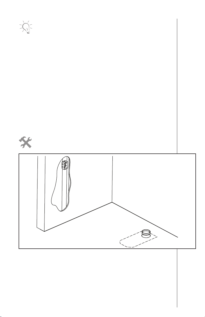
4.3 Marking the Floor
Felt marker
Fig. 4.3 a
– On the floor of an empty room (under construction or major renovations), draw
the location of stationary elements (toilet, bath, shower, counters, drawers,
permanent furnishings) that will be installed later. These marks will outline the
heating area to ensure the Therma Cable system is not placed under these
stationary elements;
– Ouellet Canada Inc. strongly recommended to install two temperature sensors
per room, where the Therma Cable will be installed. The sensor probes must be
installed between the spires of the heating cable and at a distance of 306 mm
(12’’) from each other. Note that only one sensor is connected to the thermostat,
13
Page 14

while the other will remain available as a replacement if the first one present
a malfunction. Each floor temperature sensors must be centered between two
parallel heating cables under the Therma Cable (Fig.4.3b). The ideal location
is one where it is likely to be away from stationary objects and sheltered from
outside influences (sunlight) that could skew floor temperature readings. For
maximum comfort, the area above the sensor must be free of obstruction;
– In a bathroom, when installing the Therma Cable, always allow a clearance
of at least 102 mm (4’’) on both sides of the toilet drain, this for avoiding the
melting of the toilet wax ring.
Fig. 4.3 b
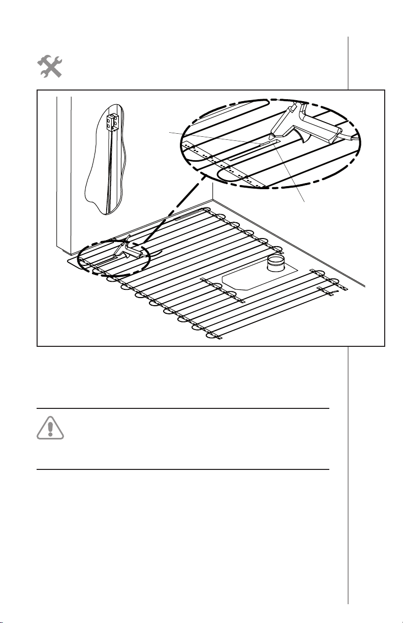
4.4 Installing the Therma Cable Floor Heating System
14
Fig. 4.4 a
cold lead
heating cable
channel
junction
Page 15

Tape, hot glue gun, stapler
Remove the product from the box and verify the electrical and
insulation resistance of the heating cable.
Therma Cable strappings’ installation:
– The strappings are fixed on the floor with staples (T50) (when the floor is made
of plywood or wood) or with a hot glue gun.
– The strappings must follow the outline draw on the room layout (Section 4.1)
– If the lacing distance between two strappings is over 0.625 m (2 ft.), it is
necessary to place an intermediate strapping to maintain the cable in position
during the pouring of self-leveller, this strapping is installed at the end, after the
lacing of the cable.
– The cable can be installed under the ceramic tile of a shower. The strapping
and the heating cable must be glued under the appropriate waterproofing
membrane (not sold by Ouellet Canada Inc.). Do not stapled, staples could
damage the waterproofing membrane.
on plywood
on concrete slab
Fig. 4.4 b
Installation of Therma Cable
– Set the cable near the connection box and regularly lace the heating wire
respecting the distance between the sections; 76 mm (3”).
– Do not bend the cable at 90° when setting it in the strapping hooks; leave a
20 mm (¾“) radius. This radius comes naturally; the cable must not be forced
to have a tight bend.
– A tag is located at 50% of the cable length. During installation of the product,
verify the cable half tag to compare with your cable layout planification. Adjust
pattern with the result to cover the surface. If the cable is too long, use the
15
Page 16

buffer zone to spend the remaining cable. Never shorten the heating cable.
The heating cable must not be shortened, neither cut.
– Avoid walking on the Therma Cable system. If you must, wear soft rubber soled
shoes;
– Always start the Therma Cable from at least 50 mm (2’’) to 76 mm (3’’)
from the walls;
– It is important not to subject the heating cable to any mechanical strain
(stretching, bending radius under 20 mm [¾”], scoring).
16
Fig. 4.4 c
IMPORTANT!
Never cut or score the heating cable.
Measure the cable’s electrical and insulation resistance and record
the readings on line 2) After installing the heating cable of the
measures’ table.
Page 17
4.5 Installing the Temperature Sensor
Hot glue gun, hammer, wood chisel or concrete chisel
temperature
sensor
channel
Fig. 4.5 a
– To minimize floor height, chisel a 10 mm X 10 mm X 250 mm (3/8” X 3/8” X 10”)
channel in the subfloor to receive the floor sensor. The junction has an insulation
sheath and a slightly larger diameter than the heating cable.
IMPORTANT!
The sensor must be embedded in cement or an equivalent binder (cement
glue, ceramic glue, self-levelling cement).
– Glue the sensors to the subfloor (Fig. 4.5a). The sensors must be solidly fastened
to the subfloor to ensure they stays in place when the cement or an equivalent
binder (cement glue, ceramic glue, self – levelling cement) is applied.
17
Page 18
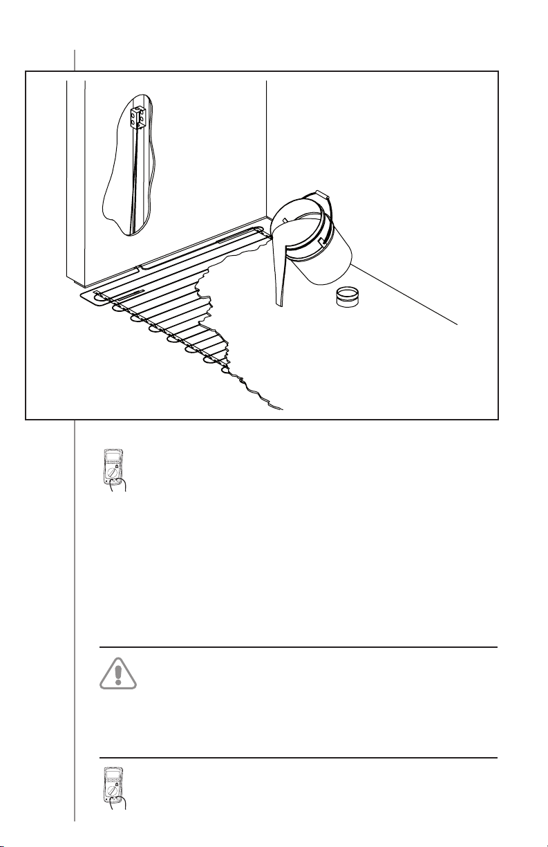
4.6 Applying Self-Levelling Cement
Fig. 4.6
Measure the cable’s electrical and insulation resistance and record the
readings on line 3) Before embedding the heating cable in self-levelling
cement of the measures’ table.
18
– Consult the manufacturer’s instruction for the type of floor covering (ceramic,
linoleum, or other). See Section 7, ”Expert Tips”;
– Completely embed the heating cable in self-levelling cement (Fig. 4.6). It is
crucial that the ENTIRE heating cable (BLACK) be embedded. No part of the
heating cable (BLACK) must be exposed. (A small part [top] of the heating cable
may be exposed at the surface of the self-levelling cement ONLY IF a ceramic
glue is used afterward AND embeds that part);
– Level the subfloor with self-levelling cement or cover the cable with a layer of
cement glue when installing the stones or ceramics.
IMPORTANT!
Do not turn on the Therma Cable floor heating system before the cement
has completely dried. Follow the manufacturer recommendations, it take’s up
to 30 days for both products (48 hours for the self-leveling cement and 30
days for the binder cement).
Once the cement or binder has dried, measure the cable’s electrical resistance and record the readings on line 4) After embedding the heating cable
in cement of the measures’ table.
Page 19

Final view
Self-levelling
cement
cement glue
4.7 Connecting the System
floor
covering
IMPORTANT!
The system must be connected by a master electrician.
Cold lead
- 240V/208V connection: - 120V connection:
Line 1–Black Line–Black
Line 2–Red Neutral–White
Bare wire–ground Bare wire–ground
Measure the cable’s electrical resistance and record the readings on line
5) Upon installing the thermostat of the measures’ table.
19
Page 20

4.8 Measuring Resistance and Measures’ table
– The master electrician who installed and connected the Therma Cable system
must complete the measures’ table (this label is available at the opening of the
product) and give it to the customer. This sheet must be kept near the electrical
service.
IMPORTANT!
If this table is not duly completed, the warranty may be annulled. Warranty
terms are set out in Section 8.
4.9 Using the Therma Cable System
– The Therma Cable floor heating system is now ready for use. However, before
turning on the system, make sure the curing period specified by the cement or
binder manufacturer has expired. Adjust the thermostat’s temperature based on
your needs and desired level of comfort.
20
Page 21

5. IMPORTANT!
The Therma Cable system must be controlled by a temperature control system.
If Therma Cable is to be used for floor warming, an electronic floor temperature
control featuring a floor sensor is recommended to ensure heat levels never exceed
the floor covering’s maximum temperature tolerance.
If the system is to be used for radiant heating, the room thermostat controls heat
and is reacting to room and not floor temperature therefore a floor covering with
greater temperature resistance must be used.
The room temperature control and floor temperature sensor must never be
installed where they will be exposed to sunlight or air drafts.
IMPORTANT!
The Therma Cable floor heating system must be connected to a ground fault
circuit interrupter (GFCI) when installed in a bathroom. Ouellet Canada Inc.
strongly recommends the use of a GFCI in all rooms featuring the
Therma Cable system.
Recommended temperature regulation devices:
1- Thermostat with floor sensor and integrated GFCI (floor warming only).
2- Rheostat dimmer switch with a GFCI.
3- Electronic ambient thermostat with a GFCI (radiant room heating).
5. Temperature Regulation
21
Page 22

6.1 Floor Heating System
Q.1: Can I cut the Therma Cable heating cable to shorten it?
A.1: NEVER. If the Therma Cable is too long, spread it on the floor in regular
loops. Keep the minimum distance from the walls and between parallel
6. FAQ
runs of cable (radius bending of at least 20 mm [¾”] for loops). Be sure
to keep 76 mm (3”) (other spacing option: 100 mm [4”]) between each
heating cable loop.
Q.2: What should I do before choosing the Therma Cable system that’s
right for me?
A.2: Make sure which power source will be used (120 or 240 Vac) to power the
heating cable or mat chosen. There must be a drawing plan to determine
the coverage area to be heated considering the elimination of the fixed
elements including: countertops, vanity, shower, bath, appliances,
wardrobes, toilet, etc. It should also be eliminated from the total surface
area a clearance of between 2’’ and 3’’ wide in respect to the surrounding
walls of the room and fixed elements.
To help you optimize your Therma Cable route running on the floor, we
must need YOUR WORK PLAN WITH ALL RELEVANT MEASUREMENTS OF
THE SURFACE TO BE HEATED by fax at 1 800 662-7801 and an assessment
will be made for this purpose.
Q.3: How do I repair Therma Cable in case of a malfunction?
A.3: First, as a PREVENTIVE measure during installation, test the cable each time
as specified in the installation guide. Also complete the measures’ table.
However, in case of a malfunction, an authorized Ouellet Canada Inc.
repair person will visit to LOCATE the fault and REPAIR it. It is recommended
that you keep spare ceramic tiles or flooring for this purpose.
22
Q.4: Are there other watt densities per square foot available?
A.4: Ouellet Canada Inc. believes that 12W/sq. ft. (130W/sq. m) at 76 mm
(3”) spacing is the best watt density to optimize comfort and prevent
floor overheating. Therma Cable can also be installed with a 100 mm
(4”) spacing for a 9W/sq. ft. (96W/sq. m). Moreover, the 240V and 120V
systems provide equal heating power per square foot.
Q.5: Can I crisscross, overlap, or touch two heating cables together?
A.5: NEVER. This will cause overheating. Keep cables at least 76 mm (3”) or
100 mm (4”) apart.
Q.6: Can the cable be bent 90°?
A.6: Yes, but make sure the radius bending is at least 20 mm (¾”). Any bending
smaller than this may damage the cable.
Page 23

6.2 Installation
Q.7: Can I install one Therma Cable system on top of another?
A.7: NEVER. The system will overheat. Heating power must not exceed
12W/sq. ft. (130W/sq. m).
Q.8: Can Therma Cable be used for exterior snow melting?
A.8: No. Therma Cable is designed to provide comfort and heating in indoor
residential applications only.
Q.9: Is a GFCI necessary?
A.9: A GFCI is required in the bathroom. It is recommended for all other rooms.
Q.10: Is a floor sensor necessary?
A.10: Yes, to control the floor surface temperature, so that it does not exceed
the maximum temperature tolerated by the type of floor covering. It is
highly recommended to install two temperature sensors supplied with
the thermostat and the product selected, but ONLY ONE SENSOR must
be connected to the internal four positions connector (on ‘ In / Sensor ‘
locations C and D) of the thermostat, while the other can serve as a spare
one, if a malfunction of the first one appear in the event. It is important to
consider that a space between both sensors must be at least of 12’’ a part
of each other. Also, both temperature sensors must be located at the same
distance (1.5’’) between the spires of the heating cable.
Q.11: Can I connect two Therma Cable systems to the same thermostat?
A.11: Yes, and even more connected in parallel but the total power consumption
must not exceed the capacity of the thermostat or power unit which the
MAXIMUM CURRENT IS LIMITED TO 15 AMPS for each of them (Ex.:
300 ft² for 240 Vac and 150 ft² for 120 Vac). Please refer to the related
tables products to find out what is the amperage consumed by the chosen
product.
Q.12: What happens if the voltage applied is the wrong one?
A.12: Connecting a 120V product to a 240V/208V current will overheat the
system and lead to an overheating and failure. A 240V/208V product
connected to a 120V current will produce virtually no heat. It is therefore
very important to connect the right product to the right voltage.
Q.13: Can Therma Cable be installed over concrete?
A.13: Yes. Apply a concrete sealer before installing the Therma Cable system.See
Section 4.
Q.14: Can carpet be installed over Therma Cable?
A.14: Yes, if the system is completely embedded in self-levelling cement. You can
install low-pile carpet over the slab if the carpet’s thermal resistance does
not exceed R = 1.40 (RSI = 0.246).
Q.15: Can wood flooring be installed over Therma Cable?
A.15: Yes, you can install multilayer wood flooring (Engineered flooring),
provided its thermal resistance does not exceed R = 1.40 (RSI = 0.246).
23
Page 24

Q.16: Is the use of self-levelling cement mandatory when installing ceramic
tile?
A.16: If the room is small, an experienced tiler can do a good job without using
self-levelling cement, but this method is not recommended. The heating
cable must always be completely embedded in cement or an equivalent
binder (cement glue, ceramic glue, self-levelling cement). If the room is
medium-sized or large, the use of self-levelling cement is strongly recommended to ensure the ceramic is perfectly level.
Q.17: Why choosing a Ouellet heating cable system (OTM or OTR) supplied
by a power source circuit of 240 Vac instead of a 120 Vac?
A.17: You can use both power sources circuit to heat a room, but it must comply
with the voltage assigned to the heating cables that are to be connected to
the chosen power source circuit.
Here in Canada, it is mainly a 240 Vac power source to which are connected
the electrical elements for heating a room. By cons, there are situations
where the only power source available is 120Vac (Ex: an old residence, an
inlet electrical box with only available 120Vac circuits breaker and in some
West states of the United States, where the only power source available is of
120 Vac).
Q.18: Can the thermostat be supplied by a 240 Vac power voltage line?
A.18: Yes, it can be supplied by both power voltages lines (120 Vac or 240 Vac).
24
Page 25

7.1 Installation Tips
– For multilayer wood flooring (engineered floor) or linoleum, it is recommended
that you consult the manufacturer to verify whether these floor coverings are
compatible with a floor heating system;
– Though unlikely, the floor temperature sensor may need to be replaced.
Ouellet Canada Inc. recommends installing a flexible plastic tube from the
sensor to the thermostat on the wall;
– Fasten the cold lead and floor sensor to a concrete subfloor with adhesive (hot
glue, tape).
7.2 Floor Covering Tips
– It is strongly recommended to coat the subfloor with a sealer before spreading
the self-levelling cement (which is very liquid). This is to prevent any leaks under
the floor;
– The use of a latex primer on a concrete subfloor is recommended to ensure the
self-levelling cement adheres better to the concrete;
– With multilayer wood flooring (engineered floor), applying a minimum 5 mm
(3/16”) layer of self-levelling cement on the heating cable is recommended. To
completely embed the cable in the cement or cement glue;
– It is important to respect the drying times recommended by the manufacturer
to prevent residual moisture from affecting the adherence of floor coverings
such as vinyl, linoleum, or wood.
7. Expert Tips: Installation and Floor Covering
25
Page 26

8.1 Warranty Statement
Subject to the legal warranties relating to quality and durability of goods provided
for by the Consumer Protection Act:
Ouellet Canada Inc. warrants the Therma Cable heating cables (OTR) of its floor
heating system for a 25-year period beginning from the date of purchase, against
any malfunction or manufacturing defect.
Limitations and exclusions
8. Warranty
The above mentioned warranties are restricted to the reimbursement of the original
purchase cost and replacement of the heating cables and/or defective thermostat
(hereinafter the “equipments”) excluding any other part also excluding any cost
or any expense relating to the connection, removal, installation or fixing of the
aforesaid equipments, including workmanship costs.
Ouellet Canada Inc. leaves the purchaser the care to choose between
reimbursement of the purchase cost or replacement of the defective equipments,
subject to the abovementioned restrictions.
The present warranties are granted to the original purchaser of the equipments as
well as to the subsequent buyer of the building where it has been installed.
Terms of warranty
The present warranties are subject to the compliance of the following terms:
I Purchaser must provide Ouellet Canada Inc. or an authorized distributor or
reseller with the original invoice for the defective equipments;
II Purchaser must notify Ouellet Canada Inc., in writing, of any defectiveness
with the equipments aimed by the present warranties, in a reasonable time
frame from the occurrence or knowledge of the defectiveness and give
permission to Ouellet Canada Inc.’s representatives, the case being, to
inspect the defective equipments;
III The equipments aimed by the present warranties must have been installed in
compliance with Ouellet Canada Inc.’s installation guidelines;
IV The equipments aimed by the present warranties must have been used in
normal conditions and must have been kept under normal maintenance from
the purchase date.
26
Name and address of the person granting the present warranty:
OUELLET CANADA INC.
180, 3e Avenue
L’Islet (Québec) G0R 2C0 CANADA
Telephone: 1 800 463-7043 or 418 247-3947
Fax: 1 800 662-7801 or 418 247-7801
info@ouellet.com
www.ouellet.com
 Loading...